EP2706151B1 - Slewing type working machine - Google Patents
Slewing type working machine Download PDFInfo
- Publication number
- EP2706151B1 EP2706151B1 EP12779443.6A EP12779443A EP2706151B1 EP 2706151 B1 EP2706151 B1 EP 2706151B1 EP 12779443 A EP12779443 A EP 12779443A EP 2706151 B1 EP2706151 B1 EP 2706151B1
- Authority
- EP
- European Patent Office
- Prior art keywords
- communication
- valve
- pilot
- line
- hydraulic
- Prior art date
- Legal status (The legal status is an assumption and is not a legal conclusion. Google has not performed a legal analysis and makes no representation as to the accuracy of the status listed.)
- Active
Links
- 238000004891 communication Methods 0.000 claims description 269
- 239000012530 fluid Substances 0.000 claims description 43
- 230000007935 neutral effect Effects 0.000 claims description 23
- 238000001514 detection method Methods 0.000 description 6
- 238000010586 diagram Methods 0.000 description 6
- 230000001172 regenerating effect Effects 0.000 description 6
- 230000001133 acceleration Effects 0.000 description 5
- 238000009937 brining Methods 0.000 description 3
- 238000011084 recovery Methods 0.000 description 3
- 230000000052 comparative effect Effects 0.000 description 2
- 230000000694 effects Effects 0.000 description 2
- 230000008929 regeneration Effects 0.000 description 2
- 238000011069 regeneration method Methods 0.000 description 2
- 238000010521 absorption reaction Methods 0.000 description 1
- 230000005281 excited state Effects 0.000 description 1
- 230000002349 favourable effect Effects 0.000 description 1
- 238000000034 method Methods 0.000 description 1
- 230000002265 prevention Effects 0.000 description 1
- 230000035939 shock Effects 0.000 description 1
Images

Classifications
-
- E—FIXED CONSTRUCTIONS
- E02—HYDRAULIC ENGINEERING; FOUNDATIONS; SOIL SHIFTING
- E02F—DREDGING; SOIL-SHIFTING
- E02F9/00—Component parts of dredgers or soil-shifting machines, not restricted to one of the kinds covered by groups E02F3/00 - E02F7/00
- E02F9/08—Superstructures; Supports for superstructures
- E02F9/10—Supports for movable superstructures mounted on travelling or walking gears or on other superstructures
- E02F9/12—Slewing or traversing gears
- E02F9/121—Turntables, i.e. structure rotatable about 360°
- E02F9/128—Braking systems
-
- F—MECHANICAL ENGINEERING; LIGHTING; HEATING; WEAPONS; BLASTING
- F15—FLUID-PRESSURE ACTUATORS; HYDRAULICS OR PNEUMATICS IN GENERAL
- F15B—SYSTEMS ACTING BY MEANS OF FLUIDS IN GENERAL; FLUID-PRESSURE ACTUATORS, e.g. SERVOMOTORS; DETAILS OF FLUID-PRESSURE SYSTEMS, NOT OTHERWISE PROVIDED FOR
- F15B15/00—Fluid-actuated devices for displacing a member from one position to another; Gearing associated therewith
- F15B15/02—Mechanical layout characterised by the means for converting the movement of the fluid-actuated element into movement of the finally-operated member
-
- E—FIXED CONSTRUCTIONS
- E02—HYDRAULIC ENGINEERING; FOUNDATIONS; SOIL SHIFTING
- E02F—DREDGING; SOIL-SHIFTING
- E02F9/00—Component parts of dredgers or soil-shifting machines, not restricted to one of the kinds covered by groups E02F3/00 - E02F7/00
- E02F9/20—Drives; Control devices
- E02F9/2058—Electric or electro-mechanical or mechanical control devices of vehicle sub-units
- E02F9/2095—Control of electric, electro-mechanical or mechanical equipment not otherwise provided for, e.g. ventilators, electro-driven fans
-
- E—FIXED CONSTRUCTIONS
- E02—HYDRAULIC ENGINEERING; FOUNDATIONS; SOIL SHIFTING
- E02F—DREDGING; SOIL-SHIFTING
- E02F9/00—Component parts of dredgers or soil-shifting machines, not restricted to one of the kinds covered by groups E02F3/00 - E02F7/00
- E02F9/20—Drives; Control devices
- E02F9/22—Hydraulic or pneumatic drives
- E02F9/2217—Hydraulic or pneumatic drives with energy recovery arrangements, e.g. using accumulators, flywheels
-
- E—FIXED CONSTRUCTIONS
- E02—HYDRAULIC ENGINEERING; FOUNDATIONS; SOIL SHIFTING
- E02F—DREDGING; SOIL-SHIFTING
- E02F9/00—Component parts of dredgers or soil-shifting machines, not restricted to one of the kinds covered by groups E02F3/00 - E02F7/00
- E02F9/20—Drives; Control devices
- E02F9/22—Hydraulic or pneumatic drives
- E02F9/226—Safety arrangements, e.g. hydraulic driven fans, preventing cavitation, leakage, overheating
-
- E—FIXED CONSTRUCTIONS
- E02—HYDRAULIC ENGINEERING; FOUNDATIONS; SOIL SHIFTING
- E02F—DREDGING; SOIL-SHIFTING
- E02F9/00—Component parts of dredgers or soil-shifting machines, not restricted to one of the kinds covered by groups E02F3/00 - E02F7/00
- E02F9/20—Drives; Control devices
- E02F9/22—Hydraulic or pneumatic drives
- E02F9/2278—Hydraulic circuits
- E02F9/2285—Pilot-operated systems
-
- E—FIXED CONSTRUCTIONS
- E02—HYDRAULIC ENGINEERING; FOUNDATIONS; SOIL SHIFTING
- E02F—DREDGING; SOIL-SHIFTING
- E02F9/00—Component parts of dredgers or soil-shifting machines, not restricted to one of the kinds covered by groups E02F3/00 - E02F7/00
- E02F9/26—Indicating devices
- E02F9/267—Diagnosing or detecting failure of vehicles
- E02F9/268—Diagnosing or detecting failure of vehicles with failure correction follow-up actions
-
- F—MECHANICAL ENGINEERING; LIGHTING; HEATING; WEAPONS; BLASTING
- F15—FLUID-PRESSURE ACTUATORS; HYDRAULICS OR PNEUMATICS IN GENERAL
- F15B—SYSTEMS ACTING BY MEANS OF FLUIDS IN GENERAL; FLUID-PRESSURE ACTUATORS, e.g. SERVOMOTORS; DETAILS OF FLUID-PRESSURE SYSTEMS, NOT OTHERWISE PROVIDED FOR
- F15B21/00—Common features of fluid actuator systems; Fluid-pressure actuator systems or details thereof, not covered by any other group of this subclass
- F15B21/14—Energy-recuperation means
-
- F—MECHANICAL ENGINEERING; LIGHTING; HEATING; WEAPONS; BLASTING
- F15—FLUID-PRESSURE ACTUATORS; HYDRAULICS OR PNEUMATICS IN GENERAL
- F15B—SYSTEMS ACTING BY MEANS OF FLUIDS IN GENERAL; FLUID-PRESSURE ACTUATORS, e.g. SERVOMOTORS; DETAILS OF FLUID-PRESSURE SYSTEMS, NOT OTHERWISE PROVIDED FOR
- F15B15/00—Fluid-actuated devices for displacing a member from one position to another; Gearing associated therewith
- F15B15/20—Other details, e.g. assembly with regulating devices
- F15B2015/206—Combined actuation, e.g. electric and fluid actuated
-
- F—MECHANICAL ENGINEERING; LIGHTING; HEATING; WEAPONS; BLASTING
- F15—FLUID-PRESSURE ACTUATORS; HYDRAULICS OR PNEUMATICS IN GENERAL
- F15B—SYSTEMS ACTING BY MEANS OF FLUIDS IN GENERAL; FLUID-PRESSURE ACTUATORS, e.g. SERVOMOTORS; DETAILS OF FLUID-PRESSURE SYSTEMS, NOT OTHERWISE PROVIDED FOR
- F15B2211/00—Circuits for servomotor systems
- F15B2211/30—Directional control
- F15B2211/305—Directional control characterised by the type of valves
- F15B2211/3056—Assemblies of multiple valves
- F15B2211/30565—Assemblies of multiple valves having multiple valves for a single output member, e.g. for creating higher valve function by use of multiple valves like two 2/2-valves replacing a 5/3-valve
-
- F—MECHANICAL ENGINEERING; LIGHTING; HEATING; WEAPONS; BLASTING
- F15—FLUID-PRESSURE ACTUATORS; HYDRAULICS OR PNEUMATICS IN GENERAL
- F15B—SYSTEMS ACTING BY MEANS OF FLUIDS IN GENERAL; FLUID-PRESSURE ACTUATORS, e.g. SERVOMOTORS; DETAILS OF FLUID-PRESSURE SYSTEMS, NOT OTHERWISE PROVIDED FOR
- F15B2211/00—Circuits for servomotor systems
- F15B2211/30—Directional control
- F15B2211/315—Directional control characterised by the connections of the valve or valves in the circuit
- F15B2211/31552—Directional control characterised by the connections of the valve or valves in the circuit being connected to an output member and a return line
- F15B2211/31558—Directional control characterised by the connections of the valve or valves in the circuit being connected to an output member and a return line having a single output member
-
- F—MECHANICAL ENGINEERING; LIGHTING; HEATING; WEAPONS; BLASTING
- F15—FLUID-PRESSURE ACTUATORS; HYDRAULICS OR PNEUMATICS IN GENERAL
- F15B—SYSTEMS ACTING BY MEANS OF FLUIDS IN GENERAL; FLUID-PRESSURE ACTUATORS, e.g. SERVOMOTORS; DETAILS OF FLUID-PRESSURE SYSTEMS, NOT OTHERWISE PROVIDED FOR
- F15B2211/00—Circuits for servomotor systems
- F15B2211/30—Directional control
- F15B2211/32—Directional control characterised by the type of actuation
- F15B2211/329—Directional control characterised by the type of actuation actuated by fluid pressure
-
- F—MECHANICAL ENGINEERING; LIGHTING; HEATING; WEAPONS; BLASTING
- F15—FLUID-PRESSURE ACTUATORS; HYDRAULICS OR PNEUMATICS IN GENERAL
- F15B—SYSTEMS ACTING BY MEANS OF FLUIDS IN GENERAL; FLUID-PRESSURE ACTUATORS, e.g. SERVOMOTORS; DETAILS OF FLUID-PRESSURE SYSTEMS, NOT OTHERWISE PROVIDED FOR
- F15B2211/00—Circuits for servomotor systems
- F15B2211/50—Pressure control
- F15B2211/505—Pressure control characterised by the type of pressure control means
- F15B2211/50509—Pressure control characterised by the type of pressure control means the pressure control means controlling a pressure upstream of the pressure control means
- F15B2211/50545—Pressure control characterised by the type of pressure control means the pressure control means controlling a pressure upstream of the pressure control means using braking valves to maintain a back pressure
-
- F—MECHANICAL ENGINEERING; LIGHTING; HEATING; WEAPONS; BLASTING
- F15—FLUID-PRESSURE ACTUATORS; HYDRAULICS OR PNEUMATICS IN GENERAL
- F15B—SYSTEMS ACTING BY MEANS OF FLUIDS IN GENERAL; FLUID-PRESSURE ACTUATORS, e.g. SERVOMOTORS; DETAILS OF FLUID-PRESSURE SYSTEMS, NOT OTHERWISE PROVIDED FOR
- F15B2211/00—Circuits for servomotor systems
- F15B2211/50—Pressure control
- F15B2211/515—Pressure control characterised by the connections of the pressure control means in the circuit
- F15B2211/5156—Pressure control characterised by the connections of the pressure control means in the circuit being connected to a return line and a directional control valve
-
- F—MECHANICAL ENGINEERING; LIGHTING; HEATING; WEAPONS; BLASTING
- F15—FLUID-PRESSURE ACTUATORS; HYDRAULICS OR PNEUMATICS IN GENERAL
- F15B—SYSTEMS ACTING BY MEANS OF FLUIDS IN GENERAL; FLUID-PRESSURE ACTUATORS, e.g. SERVOMOTORS; DETAILS OF FLUID-PRESSURE SYSTEMS, NOT OTHERWISE PROVIDED FOR
- F15B2211/00—Circuits for servomotor systems
- F15B2211/60—Circuit components or control therefor
- F15B2211/63—Electronic controllers
- F15B2211/6303—Electronic controllers using input signals
- F15B2211/6306—Electronic controllers using input signals representing a pressure
- F15B2211/6316—Electronic controllers using input signals representing a pressure the pressure being a pilot pressure
-
- F—MECHANICAL ENGINEERING; LIGHTING; HEATING; WEAPONS; BLASTING
- F15—FLUID-PRESSURE ACTUATORS; HYDRAULICS OR PNEUMATICS IN GENERAL
- F15B—SYSTEMS ACTING BY MEANS OF FLUIDS IN GENERAL; FLUID-PRESSURE ACTUATORS, e.g. SERVOMOTORS; DETAILS OF FLUID-PRESSURE SYSTEMS, NOT OTHERWISE PROVIDED FOR
- F15B2211/00—Circuits for servomotor systems
- F15B2211/60—Circuit components or control therefor
- F15B2211/63—Electronic controllers
- F15B2211/6303—Electronic controllers using input signals
- F15B2211/6336—Electronic controllers using input signals representing a state of the output member, e.g. position, speed or acceleration
-
- F—MECHANICAL ENGINEERING; LIGHTING; HEATING; WEAPONS; BLASTING
- F15—FLUID-PRESSURE ACTUATORS; HYDRAULICS OR PNEUMATICS IN GENERAL
- F15B—SYSTEMS ACTING BY MEANS OF FLUIDS IN GENERAL; FLUID-PRESSURE ACTUATORS, e.g. SERVOMOTORS; DETAILS OF FLUID-PRESSURE SYSTEMS, NOT OTHERWISE PROVIDED FOR
- F15B2211/00—Circuits for servomotor systems
- F15B2211/60—Circuit components or control therefor
- F15B2211/635—Circuits providing pilot pressure to pilot pressure-controlled fluid circuit elements
- F15B2211/6355—Circuits providing pilot pressure to pilot pressure-controlled fluid circuit elements having valve means
-
- F—MECHANICAL ENGINEERING; LIGHTING; HEATING; WEAPONS; BLASTING
- F15—FLUID-PRESSURE ACTUATORS; HYDRAULICS OR PNEUMATICS IN GENERAL
- F15B—SYSTEMS ACTING BY MEANS OF FLUIDS IN GENERAL; FLUID-PRESSURE ACTUATORS, e.g. SERVOMOTORS; DETAILS OF FLUID-PRESSURE SYSTEMS, NOT OTHERWISE PROVIDED FOR
- F15B2211/00—Circuits for servomotor systems
- F15B2211/60—Circuit components or control therefor
- F15B2211/665—Methods of control using electronic components
-
- F—MECHANICAL ENGINEERING; LIGHTING; HEATING; WEAPONS; BLASTING
- F15—FLUID-PRESSURE ACTUATORS; HYDRAULICS OR PNEUMATICS IN GENERAL
- F15B—SYSTEMS ACTING BY MEANS OF FLUIDS IN GENERAL; FLUID-PRESSURE ACTUATORS, e.g. SERVOMOTORS; DETAILS OF FLUID-PRESSURE SYSTEMS, NOT OTHERWISE PROVIDED FOR
- F15B2211/00—Circuits for servomotor systems
- F15B2211/70—Output members, e.g. hydraulic motors or cylinders or control therefor
- F15B2211/705—Output members, e.g. hydraulic motors or cylinders or control therefor characterised by the type of output members or actuators
- F15B2211/7058—Rotary output members
-
- F—MECHANICAL ENGINEERING; LIGHTING; HEATING; WEAPONS; BLASTING
- F15—FLUID-PRESSURE ACTUATORS; HYDRAULICS OR PNEUMATICS IN GENERAL
- F15B—SYSTEMS ACTING BY MEANS OF FLUIDS IN GENERAL; FLUID-PRESSURE ACTUATORS, e.g. SERVOMOTORS; DETAILS OF FLUID-PRESSURE SYSTEMS, NOT OTHERWISE PROVIDED FOR
- F15B2211/00—Circuits for servomotor systems
- F15B2211/70—Output members, e.g. hydraulic motors or cylinders or control therefor
- F15B2211/715—Output members, e.g. hydraulic motors or cylinders or control therefor having braking means
-
- F—MECHANICAL ENGINEERING; LIGHTING; HEATING; WEAPONS; BLASTING
- F15—FLUID-PRESSURE ACTUATORS; HYDRAULICS OR PNEUMATICS IN GENERAL
- F15B—SYSTEMS ACTING BY MEANS OF FLUIDS IN GENERAL; FLUID-PRESSURE ACTUATORS, e.g. SERVOMOTORS; DETAILS OF FLUID-PRESSURE SYSTEMS, NOT OTHERWISE PROVIDED FOR
- F15B2211/00—Circuits for servomotor systems
- F15B2211/70—Output members, e.g. hydraulic motors or cylinders or control therefor
- F15B2211/76—Control of force or torque of the output member
- F15B2211/761—Control of a negative load, i.e. of a load generating hydraulic energy
-
- F—MECHANICAL ENGINEERING; LIGHTING; HEATING; WEAPONS; BLASTING
- F15—FLUID-PRESSURE ACTUATORS; HYDRAULICS OR PNEUMATICS IN GENERAL
- F15B—SYSTEMS ACTING BY MEANS OF FLUIDS IN GENERAL; FLUID-PRESSURE ACTUATORS, e.g. SERVOMOTORS; DETAILS OF FLUID-PRESSURE SYSTEMS, NOT OTHERWISE PROVIDED FOR
- F15B2211/00—Circuits for servomotor systems
- F15B2211/80—Other types of control related to particular problems or conditions
- F15B2211/85—Control during special operating conditions
- F15B2211/853—Control during special operating conditions during stopping
-
- F—MECHANICAL ENGINEERING; LIGHTING; HEATING; WEAPONS; BLASTING
- F15—FLUID-PRESSURE ACTUATORS; HYDRAULICS OR PNEUMATICS IN GENERAL
- F15B—SYSTEMS ACTING BY MEANS OF FLUIDS IN GENERAL; FLUID-PRESSURE ACTUATORS, e.g. SERVOMOTORS; DETAILS OF FLUID-PRESSURE SYSTEMS, NOT OTHERWISE PROVIDED FOR
- F15B2211/00—Circuits for servomotor systems
- F15B2211/80—Other types of control related to particular problems or conditions
- F15B2211/86—Control during or prevention of abnormal conditions
- F15B2211/863—Control during or prevention of abnormal conditions the abnormal condition being a hydraulic or pneumatic failure
- F15B2211/8636—Circuit failure, e.g. valve or hose failure
-
- F—MECHANICAL ENGINEERING; LIGHTING; HEATING; WEAPONS; BLASTING
- F15—FLUID-PRESSURE ACTUATORS; HYDRAULICS OR PNEUMATICS IN GENERAL
- F15B—SYSTEMS ACTING BY MEANS OF FLUIDS IN GENERAL; FLUID-PRESSURE ACTUATORS, e.g. SERVOMOTORS; DETAILS OF FLUID-PRESSURE SYSTEMS, NOT OTHERWISE PROVIDED FOR
- F15B2211/00—Circuits for servomotor systems
- F15B2211/80—Other types of control related to particular problems or conditions
- F15B2211/88—Control measures for saving energy
Definitions
- the present invention relates to a slewing-type working machine such as an excavator.
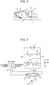
- a general excavator comprises a crawler-type base carrier 1, an upper slewing body 2 mounted on the base carrier 1 so as to be capable of slewing around an axis X perpendicular to the ground, and an excavating attachment 3 attached to the upper slewing body 2.
- the excavating attachment 3 includes: a boom 4 capable of being raised and lowered; an arm 5 attached to a tip of the boom 4; a bucket 6 attached to a tip of the arm 5; and a boom cylinder 7, an arm cylinder 8, and a bucket cylinder 9 which are respective cylinders (hydraulic cylinders) for actuating the boom 4, the arm 5, and the bucket 6.
- Fig. 4 shows an example of a conventional hydraulic circuit for slewing the upper slewing body 2.
- the circuit includes: a hydraulic pump 10 as a hydraulic pressure source that is driven by an engine not graphically shown; a slewing hydraulic motor 11 which is rotated by hydraulic pressure supplied from the hydraulic pump 10 to drive the upper slewing body 2 to slew it; a remote-control valve 12 as a slewing operation device including a lever 12a to which an operation is applied to input a command for the slewing; and a control valve 13 which is a pilot operated selector valve that can be operated by the remote-control valve 12 and provided between the hydraulic motor 11a and a pair of the hydraulic pump 10 and a tank T.
- a hydraulic pump 10 as a hydraulic pressure source that is driven by an engine not graphically shown
- a slewing hydraulic motor 11 which is rotated by hydraulic pressure supplied from the hydraulic pump 10 to drive the upper slewing body 2 to slew it
- a remote-control valve 12
- the lever 12a of the remote-control valve 12 is operated between a neutral position and right and left slewing positions, and the remote-control valve 12 outputs a pilot pressure with a magnitude corresponding to an operation amount of the lever 12a from a port corresponding to an operation direction of the lever 12a.
- the control valve 13 is switched from a graphically shown neutral position 13a to a left slewing position 13b or a right slewing position 13c by the pilot pressure, thereby controlling respective directions of supply of the hydraulic fluid to the hydraulic motor 11 and of right and left discharge of the hydraulic fluid from the hydraulic motor 11, and a flow rate of the hydraulic fluid.
- performed are: switching slewing state, that is, selectively switching to respective states of acceleration (including start-up), steady operation at a constant speed, deceleration, and stop; and controlling slewing direction and slew speed.
- the control valve 13 and respective right and left ports of the hydraulic motor 11 are interconnected through a right slewing pipe-line 15 and a left slewing pipe-line 14. Between both slewing pipe-lines 14 and 15, provided are a relief valve circuit 18, a check valve circuit 21, and a communication path 22.
- the relief valve circuit 18 is provided so as to interconnect the slewing pipe-lines 14 and 15, and the relief valve circuit 18 is provided with a pair of relief valves 16 and 17 having respective outlets which are opposed and connected to each other.
- the check valve circuit 21 is provided so as to interconnect the slewing pipe-lines 14 and 15 at a position closer to the hydraulic motor 11 than the relief valve circuit 18, and the check valve circuit 21 is provided with a pair of check valves 19 and 20 having respective inlets which are opposed and connected to each other.
- the communication path 22 interconnects a first portion of the relief valve circuit 18, the first portion located between both relief valves 16 and 17, and a second portion of the check valve circuit 21, the second portion located between both check valves 19.
- the communication path 22 is connected to the tank T through a make-up line 23 for sucking up hydraulic fluid, and the make-up line 23 is provided with a back pressure valve 24.
- the control valve 13 when the remote-control valve 12 is not operated, that is, when the lever 12a thereof is at a neutral position, the control valve 13 is kept at the neutral position 13a; when the lever 12a of the remote-control valve 12 is operated to the left or the right from the neutral position, the control valve 13 moves from the neutral position 13a to the left slewing position 13b or the right slewing position 13c in accordance with an operating direction of the lever 12a, by a stroke in accordance with an operation amount of the lever 12a.
- the control valve 13 blocks both slewing pipe-lines 14 and 15 from the pump 10 to prevent the hydraulic motor 11 from rotation; when switched to the left slewing position 13b or the right slewing position 13c, the control valve 13 allows hydraulic fluid from the pump 10 to be supplied to the left slewing pipe-line 14 or the right slewing pipe-line 15 to thereby bring the hydraulic motor 11 into a slewing-driving state of leftward or rightward rotating to slew the upper slewing body 2.
- the slewing-driving state includes both an accelerative slewing state including start-up and a steady operation state at a constant rotational speed. Meanwhile, the fluid discharged from the hydraulic motor 11 is returned to the tank T via the control valve 13.
- the control valve 13 is operated to the side of returning to the neutral position 13a to stop the supply of hydraulic fluid to the hydraulic motor 11 and the return of hydraulic fluid from the hydraulic motor 11 to the tank T, or to reduce a supply flow rate and a return flow rate of the hydraulic fluid.
- the hydraulic motor 11 continue its clockwise rotation due to the inertia of the upper slewing body 2, thus raising pressure in the left slewing pipe-line 14 as a meter-out-side line.
- the relief valve 16 on the left side in the diagram is opened to allow hydraulic fluid in the left slewing pipe-line 14 to flow into the hydraulic motor 11 through the relief valve 16, the communication path 22, the check valve 20 on the right side in the diagram, and the right slewing pipe-line 15 as indicated by a dashed-line arrow in Fig. 4 .
- Japanese Patent Application Laid-open No. 2010-65510 discloses an excavator including a circuit as shown in Fig. 4 described above, the excavator further including: a slewing electric motor connected to the hydraulic motor 11; a direct-interconnection selector valve switchable between a direct-interconnection position for directly interconnecting the left and right pipe-lines 14 and 15 and a cutoff position for cutting off the direct interconnection; an electric storage device; and a controller which switches the direct-interconnection selector valve to the direct-interconnection position during slewing deceleration to return motor-discharged fluid to a motor inlet-side and cause the slewing electric motor to perform an electric motor action, wherein the electric storage device stores regenerative power generated by the electric motor action.
- the direct-interconnection selector valve reduces back pressure that acts on a motor outlet-side during slewing deceleration to reduce drag load of the hydraulic motor. This allows efficiency of recovery (in other words, regeneration) of inertial kinetic energy to be improved.
- a communication selector valve constituted by a separate solenoid selector valve between a pilot port of the hydraulic-pilot-controlled selector valve and a hydraulic pilot pressure source; the communication selector valve is opened and closed, thus allowing turning on and off the input of the pilot pressure to the hydraulic-pilot-controlled selector valve to be performed.
- Patent Document 1 Japanese Patent Application Laid-open No. 2010-65510
- An object of the present invention is to provide a slewing-type working machine which is capable of improving energy recovery efficiency by reducing motor load at least during slewing deceleration, by use of a hydraulic-pilot-controlled selector valve and a communication selector valve for switching supply of pilot pressure to the hydraulic-pilot-controlled selector valve and which is capable of holding an upper slewing body in a stopped state even when a failure attributable to fixation of a spool or the like of the communication selector valve occurs.
- the slewing-type working machine includes: a base carrier; an upper slewing body mounted on the base carrier so as to be capable of being slewed; a hydraulic motor which includes first and second ports and which receives supply of hydraulic fluid through one of the first and second ports and discharges the hydraulic fluid through the other port to thereby operate so as to drive the upper slewing body to slew it; a hydraulic pump which discharges the hydraulic fluid to be supplied to the hydraulic motor; a first pipe-line; a second pipe-line; a slewing operation device including an operating member to which an operation is applied to input a command for the driving to slew and being adapted to output an operation signal corresponding to the operation applied to the operating member; a control valve connected to the first port and the second port of the hydraulic motor through the first pipe-line and the second pipe-line, respectively, the control valve being adapted to be operated, based on the operation signal from the slewing operation device, to control supply of hydraulic fluid to the hydraulic motor and control
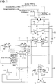
- Fig. 1 shows a hydraulic circuit according to the first embodiment of the present invention.
- the circuit includes: a hydraulic pump 10 as a hydraulic pressure source, which is driven by an engine not graphically shown; a slewing hydraulic motor 11 which is rotated by supply of hydraulic fluid discharged from the hydraulic pump 10 to drive the upper slewing body 2 to slew it, a remote-control valve 12 as a slewing operation device including a lever 12a to which an operation is applied to input a slewing command; and a control valve 13 which is a pilot-controlled selector valve capable of being operated by the remote-control valve 12 and is provided between the hydraulic motor 11 and a pair of the hydraulic pump 10 and a tank T.
- a hydraulic pump 10 as a hydraulic pressure source, which is driven by an engine not graphically shown
- a slewing hydraulic motor 11 which is rotated by supply of hydraulic fluid discharged from the hydraulic pump 10 to drive the upper slewing body 2 to slew it
- a remote-control valve 12
- the hydraulic motor 11 includes a left port 11a and a right port 11b which are first and second ports, respectively.
- the hydraulic motor 11 When supplied with hydraulic fluid through the left port 11a, the hydraulic motor 11 discharges the hydraulic fluid through the right port 11b to leftward slew the upper slewing body 2 shown in Fig. 3 .
- the hydraulic motor 11 Conversely, when supplied with hydraulic fluid through the right port 11b, the hydraulic motor 11 discharges the hydraulic fluid through the left port 11a to rightward slew the upper slewing body 2.
- the lever 12a of the remote-control valve 12 is operated between a neutral position and right and left slewing positions, and the remote-control valve 12 outputs pilot pressure with a magnitude corresponding to an operation amount of the lever 12a from a port corresponding to an operation direction of the lever 12a.
- the control valve 13 is switched from a graphically shown neutral position 13a to a left slewing position 13b or a right slewing position 13c by the pilot pressure, thereby controlling respective directions of supply of the hydraulic fluid to the hydraulic motor 11 and of right and left discharge of the hydraulic fluid from the hydraulic motor 11, and a flow rate of the hydraulic fluid.
- performed are: switching slewing state, that is, selectively switching to respective states of acceleration (including start-up), steady operation at a constant speed, deceleration, and stop; and controlling slewing direction and slew speed.
- the circuit includes a left slewing pipe-line 14 and a right slewing pipe-line 15 which are the first and second pipe-lines, respectively, a relief valve circuit 18, a check valve circuit 21, a communication path 22, and a make-up line 23.
- the left slewing pipe-line 14 connects the control valve 13 to the left port 11a of the hydraulic motor 11, and the right slewing pipe-line 15 connects the control valve 13 to the right port 11b of the hydraulic motor 11.
- the control valve 13 is adapted: to cut off both left and right pipe-lines 14 and 15 from the hydraulic pump 10 and the tank T to stop the flow of the hydraulic fluid, at the neutral position 13a; to connect the hydraulic pump 10 to the left slewing pipe-line 14 and bring the right slewing pipe-line 15 into communication with the tank, at the left rotational position 13b; and to connect the hydraulic pump 10 to the right slewing pipe-line 15 and bring the left slewing pipe-line 14 into communication with the tank, at the right rotational position 13c.
- the relief valve circuit 18, the check valve circuit 21, and the communication path 22 are provided between the slewing pipe-lines 14 and 15.
- the relief valve circuit 18 is provided so as to interconnect the slewing pipe-lines 14 and 15.
- the relief valve circuit 18 includes a pair of relief valves 16 and 17 having respective outlets which are opposed and connected to each other.
- the check valve circuit 21 is arranged parallel to the relief valve circuit 18 at a position closer to the hydraulic motor 11 than the relief valve circuit 18 so as to interconnect the slewing pipe-lines 14 and 15.
- the check valve circuit 21 includes a pair of check valves 19 and 20 having respective inlets of the check valves 19 and 20 which are opposed and connected to each other.
- the communication path 22 interconnects a first portion of the relief valve circuit 18, the first portion located between the relief valves 16 and 17, and a second portion of the check valve circuit 21, the second portion located between the check valves 19 and 20.
- the makeup line 23 connects the communication path 22 to the tank T in order to suck up hydraulic fluid.
- the makeup line 23 is provided with a back pressure valve 24.
- the circuit according to the first embodiment further includes: a left communication valve 25 and a right communication valve 26 which are respective first communication valve and second communication valve; a pilot pump 28; a left communication selector valve 32 and a right communication selector valve 33 which are respective first communication selector valve and the second communication selector valve provided for the left and right communication valves 25 and 26, respectively; a slewing electric motor 35 capable of being rotationally driven by the hydraulic motor 11; an electric storage device 36; pressure sensors 37 and 38 which are respective operation detectors; a speed sensor 39 which is a speed detector; a lock valve 41; and a controller 42.
- the communication valves 25 and 26 comprise respective hydraulic-pilot-controlled selector valves having respective pilot ports 25a and 26a.
- the communication valves 25 and 26 include respective inlet-side ports connected to the slewing pipe-lines 14 and 15 and respective outlet-side ports connected via a passage 27 to a part of the relief valve circuit 18, the part located between the relief valves 16 and 17.
- the respective slewing pipe-lines 14 and 15 are brought into direct communication with the tank T while bypassing the control valve 13 when the respective communication valves 25 and 26 are set to the open position "a".
- the pilot pump 28 is a pilot pressure hydraulic source which generates pilot pressure to be supplied to the communication valves 25 and 26, while being also used, in the present embodiment, as a hydraulic pressure source which supplies inlet pilot pressure to the remote-control valve 12.
- the pilot pressure generated by the pilot pump 28 can be supplied to the communication valves 25 and 26 via a pilot line and can also be supplied to the remote-control valve 12 as inlet pilot pressure thereof.
- the pilot line includes a pilot pump line (hydraulic-pilot-pressure-source line) 29 which is a discharge line connected to a discharge side of the pilot pump 28, and a plurality of lines branching parallel to each other from the pilot pump line 29, namely: a first-communication-valve pilot line 30, a second-communication-valve pilot line 31, and a remote-control-valve inlet pressure line 40.
- the first and second-communication-valve pilot lines 30 and 31 are connected to the pilot ports 25a and 26a of the left and right communication valves 25 and 26, respectively, and the remote-control-valve-inlet-pressure line 40 is connected to an inlet side of the remote-control valve 12.
- the left and right communication selector valves 32 and 33 which are to switch the supply of pilot pressure to the communication valves 25 and 26, in other words, to control switching of the communication selector valves 32 and 33, are provided midway the first and second-communication-valve pilot lines 30 and 31, respectively.
- the communication selector valves 32 and 33 have respective pilot pressure supply positions "a" for allowing the pilot pressure from the pilot pump 28 to be supplied to the communication valves 25 and 26 and respective pilot pressure cutoff positions "b" for cutting off the supply of the pilot pressure.
- the communication selector valves 32 and 33 are set to the pilot pressure supply position "a" only upon input of a switching command signal outputted from the controller 42 as will be described later.
- the pressure sensors 37 and 38 detect the operations applied to the remote-control valve 12 through respective pilot pressures outputted from the remote-control valve 12, in other words, detect whether the lever 12a is located at the neutral position or an operation for a leftward slewing or a rightward slewing is applied. Specifically, the pressure sensors 37 and 38 output respective operation signals corresponding to respective pilot pressures outputted from the remote-control valve 12.
- the speed sensor 39 detects a rotational speed of the slewing electric motor 35, that is, a speed corresponding to a slew speed of the upper slewing body 2, and outputs a slew speed detection signal.
- the controller 42 based on the operation detection signal inputted from the pressure sensors 37 and 38 and on the slew speed detection signal inputted from the speed sensor 39, judges whether the upper slewing body 2 is being driven for slewing (accelerating including start-up or in steady operation), decelerated, or in a stopped state.
- the controller 42 issues a command for switching only one of the communication valves 25 and 26, the communication valve opposite to the operated communication valve, in other words, the communication valve connected to a pipe-line corresponding to a discharge-side pipe-line of the slewing pipe-lines 14 and 15, to the open position "a" (hereinafter, the communication valve connected to the discharge-side pipe-line will be indicated as a "outlet-side communication valve", which corresponds to, during a rightward slewing, the left communication valve 25 connected to the left slewing pipe-line 14, while corresponds to, during a leftward slewing, the right communication valve 26 that connects to the right slewing pipe-line 15).
- the controller 42 outputs, only to a communication selector valve corresponding to the outlet-side communicating valve (during a rightward slewing, the left communication selector valve 32 which corresponds to the left communicating valve 25, and during a leftward slewing, the right communicating valve 33 that connects to the right communicating valve 26: hereinafter referred to as an "outlet-side communication selector valve"), a switching command signal (a drive signal which excites a solenoid of the outlet-side communication selector valve) to switch the outlet-side communication selector valve to the pilot pressure supply position "a".
- a switching command signal a drive signal which excites a solenoid of the outlet-side communication selector valve
- hydraulic fluid discharged from the hydraulic motor 11 to the left slewing pipe-line 14 or the right slewing pipe-line 15 during driving for slewing passes through the communication valve 25 or 26 that is connected to the discharge-side pipe-line to be directly returned to the tank T, while bypassing the control valve 13.
- hydraulic fluid discharged from the hydraulic motor 11 sequentially passes through the left slewing pipe-line 14, the left communication valve 25, the passage 27, the communication path 22, and the make-up line 23 before returning to the tank T.
- the slewing electric motor 29 is rotated so as to be involved by the hydraulic motor 11. In other words, the slewing electric motor 29 is driven by the hydraulic motor 11.
- the hydraulic fluid circulates so as to be returned to the right slewing pipe-line 15 from the communication path 22 through the right check valve 20 of the check valve circuit 21.
- the slewing electric motor 35 performs a generator (regenerative) action, based on a regeneration command from the controller 42, thus exerting a braking force against the rotation of the hydraulic motor 11 and transmitting the generated regenerative power to the electric storage device 36 to charge it.
- the regenerative action causes a brake against the rotation of the hydraulic motor 11 to decelerate/stop the upper slewing body 2. Then, in the slewing stopped state, the controller 42 switches both of the communication selector valves 32 and 33 to the pilot pressure cutoff position "b" to set both of the communication valves 25 and 26 to the communication cutoff position "b". The flow of the fluid in the circuit and the rotation of the hydraulic motor 11 due to the flow are thereby blocked and the upper slewing body 2 is held in a stopped state.
- the fluid discharged from the hydraulic motor 11 is returned to the tank T by the communication valves 25 and 26 while bypassing the control valve 13, which makes it possible to eliminate the back pressure attributable to a throttle action of the control valve 13.
- the first embodiment includes a not-graphically-shown lock lever which performs opening and closing a gate of the machine and a lock valve 41 as a switching control valve.
- the lock valve 41 comprises a solenoid selector valve and is provided midway the pilot pump line 29 on an inlet side of the remote-control valve 12 and the communication selector valves 32 and 33.
- the lock valve 41 is switched, by a switching command signal inputted from the controller 42, between a pilot pressure supply position "a" for opening the pilot pump line 29 to allow the pilot pressure to be supplied (that is, a connection position for connecting the pilot pump 28 to both of the communication selector valves 32 and 33) and a tank communication position "b" for cutting off the pilot pump line 29 in the midway thereof and bringing the respective communication selector valves 32 and 33 and the inlet side of the remote-control valve 12 into communication with the tank T (in other words, a cutoff position for cutting off the pilot pump 28 from both of the communication selector valves 32 and 33).
- the excavator according to the first embodiment further comprises a lever detector (not shown) which detects an operation applied to the lock lever in a direction for the opening performed by an operator to exit the excavator and which outputs a detection signal thereof (the detector may be a contact switch such as a limiter switch and a micro switch or a contactless switch such as a photoelectric switch). Based on the detection signal outputted by the lever detector, the controller 42 issues, in a slewing stopped state, a command for making the solenoid of the lock valve 41 be non-excited to switch the lock valve 41 from the pilot pressure supply position "a" to the graphically shown tank communication position "b".
- a lever detector (not shown) which detects an operation applied to the lock lever in a direction for the opening performed by an operator to exit the excavator and which outputs a detection signal thereof
- the controller 42 Based on the detection signal outputted by the lever detector, the controller 42 issues, in a slewing stopped state, a command for making the solenoid of the
- the lock valve 41 thus switched to the tank communication position "b" cuts off the supply of the inlet pilot pressure from the pilot pump 28 to the remote-control valve 12 to make operations applied to the remote-control valve 12 be inoperable, that is, to create a so-called locked state, thus disabling the control valve 13 from being operated, that is, disabling the upper slewing body 2 from slewing, and further bringing respective inlet sides of the communication selector valves 32 and 33 into communication with the tank T to thereby disable the pilot pressure from being supplied to the communication selector valves 32 and 33.
- the communication-valve pilot lines 30 and 31 are branched in parallel, together with the remote-control-valve-inlet-pressure line 40, on the outlet side of the lock valve 41, and provided with respective communication selector valves 32 and 33; therefore, switching the lock valve 41 to the tank communication position "b" not only makes operations applied to the remote-control valve 12 be inoperable but also disables the pilot pressure from being supplied to the communication valves 25 and 26 through the communication selector valves 32 and 33 regardless of actual positions of the communication selector valves 32 and 33.
- the lock valve 41 in the slewing stopped state, prevents pilot pressure from being supplied to the communication valves 25 and 26, thereby reliably holding each of the communication valves 25 and 26 at the communication cutoff position "b" to prevent the hydraulic motor 11 from rotation.
- the circuit shown in Fig. 5 also comprises a lock valve 41 similarly to the circuit shown in Fig. 1 , the lock valve 41 is provided not in the midway of the pilot pump line 29 but in the midway of the remote-control-valve-inlet-pressure line 40 branched from the pilot pump line 29, having an open position "a" for opening the line 40 and a cutoff position "b" for cutting off the line 40 in the midway thereof to bring into communication with the tank T.
- neither of the communication selector valves 32 and 33 are brought into communication with the tank T whichever the lock valve 41 is changed at the position a or b; therefore, if the outlet-side communication selector valve of the communication selector valves 32 and 33 becomes immobilized at the pilot supply position "a" due to an occurrence of spool fixation or the like at the outlet-side communication selector valve, hydraulic fluid discharged from the hydraulic motor 11 is inevitably let to the tank T through the outlet-side communication selector valve that is immobilized at the pilot supply position in spite that the control valve 13 has been returned to the neutral position 13a, which makes it impossible to prevent the hydraulic motor 11 from rotation.
- the controller 42 can reliably prevent pilot pressure from being supplied to the communication valves 25 and 26 through the communication selector valves 32 and 33, by switching the lock valve 41 to the tank communication position "b" in a slewing stopped state, to hold both of the communication valves 25 and 26 at the communication cutoff position "b" regardless of the positions of the communication selector valves 32 and 33 (for example, even if any of the communication selector valves 32 and 33 is immobilized at the pilot supply position "a" due to an occurrence of spool fixation or the like) in addition to making the remote-control valve 12 inoperable, thus making prevention of the hydraulic motor 11 from rotation and holding the upper slewing body 2 in a slewing stopped state be reliable.
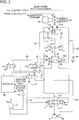
- the work machine according to the second embodiment comprises, in addition to the components according to the first embodiment described above, a slewing parking brake 43 which mechanically holds the upper slewing body 2 in a stopped state, and also comprises a brake control valve 44 for controlling brake actuation/brake release of the slewing parking brake 43, in place of the lock valve 41 according to the first embodiment.
- the slewing parking brake 43 is switchable between a braking state of holding the upper slewing body 2 and a brake release state of releasing the holding and is configured as a negative brake which is switched to the brake release state by hydraulic pressure outputted from the pilot pump 28.
- the pilot line according to the second embodiment includes a brake line 45 branched from the pilot pump line 29 in parallel with the communication-valve pilot lines 32 and 33 and connected to the slewing parking brake 43.
- the slewing parking brake 43 includes a spring for applying brake force to the upper slewing body 2 in a state where no hydraulic pressure is introduced from the pilot pump 28 through the brake line 45.
- the hydraulic pressure is inputted to the slewing parking brake 43 so as to release the brake force of the spring against the force thereof.
- the brake control valve 44 also comprises a solenoid selector valve and is provided midway of the pilot pump line 29 on the inlet side of the communication selector valves 32 and 33, and is switched to a pilot pressure supply position "a" for opening the pilot pump line 29 (in other words, a connecting position for connecting the pilot pump 28 to both of the communication selector valves 32 and 33) and a tank communication position "b" for cutting off the pilot pump line 29 midway to bring the pilot pump line 29 into communication with the tank T (in other words, a cutoff position for cutting off the pilot pump 28 from both of the communication selector valves 32 and 33) by switching command signals inputted from the controller 42.
- a for opening the pilot pump line 29
- a tank communication position "b” for cutting off the pilot pump line 29 midway to bring the pilot pump line 29 into communication with the tank T (in other words, a cutoff position for cutting off the pilot pump 28 from both of the communication selector valves 32 and 33) by switching command signals inputted from the controller 42.
- the controller 42 issues a switching command for the brake control valve 44 based on an operation detection signal that is inputted from the pressure sensors 37 and 38. Specifically, during a slewing operation (including several seconds after a slewing stop operation has been performed) of the remote-control valve 12, the controller 42 makes the solenoid of the brake control valve 44 be non-excited to set the brake control valve 44 to the pilot pressure supply position "a", while, in a slewing stopped state, the controller 42 makes the solenoid be excited to switch the brake control valve 44 to the tank communication position "b".
- the controller 42 switching the brake control valve 44 to the tank communication position "b" in a slewing stopped state, can not only cut off the supply of hydraulic pressure to the slewing parking brake 43 to bring the slewing parking brake 43 into a brake operation state, but also reliably prevent pilot pressure from being supplied to the communication valves 25 and 26 via the communication selector valves 32 and 33 regardless of the actual positions of the communication selector valves 32 and 33.
- the hydraulic motor 11 can be prevented from rotation in spite that the control valve 13 stays at the neutral position 13a.
- a fail-safe function with respect to a failure attributable to fixation of a spool or the like at the communication selector valves 32 and 33 is thus exerted, which allows the upper slewing body to be reliably held in the stopped state to enhance safety.
- the lock valve 41 and the brake control valve 44 which are solenoid selector valves for switching locking of the remote-control valve 12 or switching operations of the slewing parking brake 43 in accordance with rotation/rotation stop are utilized as switch control valves for the fail safe; this makes it possible to simplify circuit configuration and reduce facility cost, compared to a case of separately adding a dedicated switch control valve for the fail safe.
- the lock valve 41 used as a switching control valve in the first embodiment adapted to be switched to a non-excited state in a slewing stopped state conversely to the brake control valve 44 according to the second embodiment, can maintain the fail-safe function even if a failure such as disconnection of a solenoid occurs in the lock valve 41. This allows the safety of the work machine to be further improved.
- the present invention is not limited to the first and second embodiments described above but includes embodiments as follows.
- the present invention provides a slewing-type working machine which is capable of improving energy recovery efficiency by reducing motor load at least during slewing deceleration, by use of a hydraulic-pilot-controlled selector valve and a communication selector valve for switching supply of pilot pressure to the hydraulic-pilot-controlled selector valve and which is capable of holding an upper slewing body in a stopped state even when a failure attributable to fixation of a spool or the like of the communication selector valve occurs.
- the slewing-type working machine includes: a base carrier; an upper slewing body mounted on the base carrier so as to be capable of being slewed; a hydraulic motor which includes first and second ports and receives supply of hydraulic fluid through one of the first and second ports and discharges the hydraulic fluid through the other port to thereby operate so as to drive the upper slewing body to slew it; a hydraulic pump which discharges the hydraulic fluid to be supplied to the hydraulic motor; a first pipe-line; a second pipe-line; a slewing operation device including an operating member to which an operation is applied to input a command for the driving to slew and being adapted to output an operation signal corresponding to the operation applied to the operating member; a control valve connected to the first port and the second port of the hydraulic motor through the first pipe-line and the second pipe-line, respectively, the control valve being adapted to be operated, based on the operation signal from the slewing operation device, to control supply of hydraulic fluid to the hydraulic motor and control discharge
- switching control valve As the switching control valve according to the present invention, various selector valves that are switched in a rotation stopped state for other purposes can be utilized, as well as the specifically-provided switching control valve described earlier. Such a utilization enables circuit configuration to be simplified as compared to a case of separately adding a dedicated switching control, thus allowing facility cost to be reduced.
- the switching control valve may be a lock valve having a connecting position for connecting the hydraulic pilot pressure source to the remote-control valve in addition to the communication selector valve and permitting supply of inlet pilot pressure from the hydraulic pilot pressure source to the remote-control valve and a cutoff position for cutting off the communication selector valve and the remote-control valve from the hydraulic pilot pressure source, and the controller may issue a command for switching the lock valve to the cutoff position when an lock lever which performs opening and closing a gate of the work machine is operated for opening.
- the controller is enabled to prevent the supply of inlet pilot pressure from the hydraulic pilot pressure source to the remote-control valve to disable the remote-control valve from being operated, that is, to lock the remote-control valve and, at the same time, prevent pilot pressure from being supplied from the hydraulic pilot pressure source to the communication selector valve.
- the pilot line preferably includes a hydraulic-pilot-pressure-source line connected to the hydraulic pilot pressure source, a communication-valve pilot line branched from the hydraulic-pilot-pressure-source line and connected to the communication selector valve, and a remote-control-valve-inlet-pressure line branched from the hydraulic-pilot-pressure-source line and connected to the remote-control valve, wherein the lock valve is provided on the hydraulic-pilot-pressure-source line.
- the lock valve preferably comprises a solenoid selector valve including a solenoid and being adapted to be held at the connecting position when the solenoid is non-excited.
- the lock valve comprising such a solenoid selector valve can be held at the connecting position even if a failure such as disconnection of the solenoid of the lock valve occurs to maintain a fail-safe function, thereby further improving the safety of the work machine.
- the switching control valve is a brake control valve having a connecting position for connecting the hydraulic pilot pressure source to the slewing parking brake in addition to the communication selector valve to allow hydraulic pressure to be supplied from the hydraulic pilot pressure source to the slewing parking brake and a cutoff position for cutting off the communication selector valve and the slewing parking brake from the hydraulic pilot pressure source; and the controller issues a command for switching the brake control valve to the cutoff position in a slewing stopped state.
- the controller can prevent the hydraulic pressure from being supplied from the hydraulic pilot pressure source to the slewing parking brake to thereby bring the slewing parking brake into a braking state and hold the upper slewing body in a stopped state and, at the same time, prevent the pilot pressure from being supplied from the hydraulic pilot pressure source to each of the switching control valves.
- the pilot line includes a hydraulic-pilot-pressure-source line connected to the hydraulic pilot pressure source, a communication-valve pilot line which is branched from the hydraulic-pilot-pressure-source line and connected to the communication selector valve, and a brake line which is branched from the hydraulic-pilot-pressure-source line and connected to the slewing parking brake, wherein the brake control valve is provided on the hydraulic-pilot-pressure-source line.
- a first communication valve provided between the first pipe-line and the tank and switched between an opened position for bringing the first pipe-line into communication with the tank and a closed position for cutting off the first pipe-line and the tank from each other; and a second communication valve provided between the second pipe-line and the tank and switched between an opened position for bringing the second pipe-line into communication with the tank and a closed position for cutting off the second pipe-line from the tank.
- the pilot line includes a hydraulic-pilot-pressure-source line connected to the hydraulic pilot pressure source, a first-communication-valve pilot line branched from the hydraulic-pilot-pressure-source line and connected to the first communication valve, and a second-communication-valve pilot line branched from the hydraulic-pilot-pressure-source line in parallel to the first-communication-valve pilot line and connected to the second communication valve;
- the communication selector valve a first communication selector valve provided on the first-communication-valve pilot line and switched between a pilot pressure supply position for opening the first-communication-valve pilot line to allow pilot pressure to be supplied to the first communication valve and a pilot pressure cutoff position for cutting off the first-communication-valve pilot line to cut off supply of the pilot pressure to the first communication valve and a second communication selector valve provided on the second-communication-valve pilot line and switched between a pilot pressure supply position for opening the second-communication-valve pilot line to allow pilot pressure to be supplied to the second communication valve and a pilot pressure cutoff position
Description
- The present invention relates to a slewing-type working machine such as an excavator.
- The background art of the present invention will be described using an excavator as an example.
- For example, as shown in
Fig. 3 , a general excavator comprises a crawler-type base carrier 1, anupper slewing body 2 mounted on thebase carrier 1 so as to be capable of slewing around an axis X perpendicular to the ground, and anexcavating attachment 3 attached to theupper slewing body 2. Theexcavating attachment 3 includes: a boom 4 capable of being raised and lowered; anarm 5 attached to a tip of the boom 4; abucket 6 attached to a tip of thearm 5; and a boom cylinder 7, anarm cylinder 8, and a bucket cylinder 9 which are respective cylinders (hydraulic cylinders) for actuating the boom 4, thearm 5, and thebucket 6. -
Fig. 4 shows an example of a conventional hydraulic circuit for slewing theupper slewing body 2. The circuit includes: ahydraulic pump 10 as a hydraulic pressure source that is driven by an engine not graphically shown; a slewinghydraulic motor 11 which is rotated by hydraulic pressure supplied from thehydraulic pump 10 to drive theupper slewing body 2 to slew it; a remote-control valve 12 as a slewing operation device including alever 12a to which an operation is applied to input a command for the slewing; and acontrol valve 13 which is a pilot operated selector valve that can be operated by the remote-control valve 12 and provided between thehydraulic motor 11a and a pair of thehydraulic pump 10 and a tank T. - The
lever 12a of the remote-control valve 12 is operated between a neutral position and right and left slewing positions, and the remote-control valve 12 outputs a pilot pressure with a magnitude corresponding to an operation amount of thelever 12a from a port corresponding to an operation direction of thelever 12a. Thecontrol valve 13 is switched from a graphically shownneutral position 13a to aleft slewing position 13b or aright slewing position 13c by the pilot pressure, thereby controlling respective directions of supply of the hydraulic fluid to thehydraulic motor 11 and of right and left discharge of the hydraulic fluid from thehydraulic motor 11, and a flow rate of the hydraulic fluid. In other words, performed are: switching slewing state, that is, selectively switching to respective states of acceleration (including start-up), steady operation at a constant speed, deceleration, and stop; and controlling slewing direction and slew speed. - The
control valve 13 and respective right and left ports of thehydraulic motor 11 are interconnected through a right slewing pipe-line 15 and a left slewing pipe-line 14. Between both slewing pipe-lines relief valve circuit 18, acheck valve circuit 21, and acommunication path 22. Therelief valve circuit 18 is provided so as to interconnect the slewing pipe-lines relief valve circuit 18 is provided with a pair ofrelief valves check valve circuit 21 is provided so as to interconnect the slewing pipe-lines hydraulic motor 11 than therelief valve circuit 18, and thecheck valve circuit 21 is provided with a pair ofcheck valves communication path 22 interconnects a first portion of therelief valve circuit 18, the first portion located between bothrelief valves check valve circuit 21, the second portion located between bothcheck valves 19. Thecommunication path 22 is connected to the tank T through a make-up line 23 for sucking up hydraulic fluid, and the make-up line 23 is provided with aback pressure valve 24. - In this circuit, when the remote-
control valve 12 is not operated, that is, when thelever 12a thereof is at a neutral position, thecontrol valve 13 is kept at theneutral position 13a; when thelever 12a of the remote-control valve 12 is operated to the left or the right from the neutral position, thecontrol valve 13 moves from theneutral position 13a to theleft slewing position 13b or theright slewing position 13c in accordance with an operating direction of thelever 12a, by a stroke in accordance with an operation amount of thelever 12a. - At the
neutral position 13a, thecontrol valve 13 blocks both slewing pipe-lines pump 10 to prevent thehydraulic motor 11 from rotation; when switched to theleft slewing position 13b or theright slewing position 13c, thecontrol valve 13 allows hydraulic fluid from thepump 10 to be supplied to the left slewing pipe-line 14 or the right slewing pipe-line 15 to thereby bring thehydraulic motor 11 into a slewing-driving state of leftward or rightward rotating to slew theupper slewing body 2. The slewing-driving state includes both an accelerative slewing state including start-up and a steady operation state at a constant rotational speed. Meanwhile, the fluid discharged from thehydraulic motor 11 is returned to the tank T via thecontrol valve 13. - Next will be described deceleration of slewing. For example, in the rightward slewing, i.e., clockwise slewing, upon a deceleration operation applied to the remote-
control valve 12, specifically, upon an operation for returning thelever 12a to the neutral position or to the side of the neutral position, thecontrol valve 13 is operated to the side of returning to theneutral position 13a to stop the supply of hydraulic fluid to thehydraulic motor 11 and the return of hydraulic fluid from thehydraulic motor 11 to the tank T, or to reduce a supply flow rate and a return flow rate of the hydraulic fluid. Meanwhile, thehydraulic motor 11 continue its clockwise rotation due to the inertia of theupper slewing body 2, thus raising pressure in the left slewing pipe-line 14 as a meter-out-side line. When the raised pressure reaches a certain value, therelief valve 16 on the left side in the diagram is opened to allow hydraulic fluid in the left slewing pipe-line 14 to flow into thehydraulic motor 11 through therelief valve 16, thecommunication path 22, thecheck valve 20 on the right side in the diagram, and the right slewing pipe-line 15 as indicated by a dashed-line arrow inFig. 4 . This gives a braking force due to the action of therelief valve 16 against thehydraulic motor 11 which continues to rotate due to the inertia, thereby decelerating and stopping thehydraulic motor 11. Decelerating and stopping the leftward slewing are similarly performed. On the other hand, when the slewing pipe-line line up line 23, thecommunication path 22 and thecheck valve circuit 21, thereby preventing cavitation. - Japanese Patent Application Laid-open No.
2010-65510 Fig. 4 described above, the excavator further including: a slewing electric motor connected to thehydraulic motor 11; a direct-interconnection selector valve switchable between a direct-interconnection position for directly interconnecting the left and right pipe-lines - Although the known art described in Japanese Patent Application Laid-open No.
2010-65510 - However, in this case, if a phenomenon such as fixation of a spool of the communication selector valve or the like occurs and causes such a failure that the communication selector valve is prevented from a movement from a pilot pressure supply position, there may be continued a state where pilot pressure is supplied to the hydraulic-pilot-controlled selector valve even after slewing has stopped. Hence, for example, in the case where the direct-interconnection selector valve is made up of the hydraulic-pilot-controlled selector valve, the direct-interconnection selector valve is brought into a state of directly interconnecting both of the pipe-lines, which makes it impossible to prevent the hydraulic motor and the upper slewing body connected thereto from rotation. This generates a fear of allowing an upper slewing body to slew due to its own weight on inclined ground or the like.
- Patent Document 1: Japanese Patent Application Laid-open No.
2010-65510 - An object of the present invention is to provide a slewing-type working machine which is capable of improving energy recovery efficiency by reducing motor load at least during slewing deceleration, by use of a hydraulic-pilot-controlled selector valve and a communication selector valve for switching supply of pilot pressure to the hydraulic-pilot-controlled selector valve and which is capable of holding an upper slewing body in a stopped state even when a failure attributable to fixation of a spool or the like of the communication selector valve occurs. The slewing-type working machine provided by the present invention includes: a base carrier; an upper slewing body mounted on the base carrier so as to be capable of being slewed; a hydraulic motor which includes first and second ports and which receives supply of hydraulic fluid through one of the first and second ports and discharges the hydraulic fluid through the other port to thereby operate so as to drive the upper slewing body to slew it; a hydraulic pump which discharges the hydraulic fluid to be supplied to the hydraulic motor; a first pipe-line; a second pipe-line; a slewing operation device including an operating member to which an operation is applied to input a command for the driving to slew and being adapted to output an operation signal corresponding to the operation applied to the operating member; a control valve connected to the first port and the second port of the hydraulic motor through the first pipe-line and the second pipe-line, respectively, the control valve being adapted to be operated, based on the operation signal from the slewing operation device, to control supply of hydraulic fluid to the hydraulic motor and control discharge of hydraulic fluid from the hydraulic motor and adapted to be held at a neutral position for cutting off both the first and second pipe-lines from the hydraulic pump and the tank when the operation signal is absent; a communication valve which comprises a hydraulic-pilot-controlled selector valve having a pilot port, the communication valve being adapted to be switched to a communication position for bringing a pipe-line corresponding to an outlet-side pipe-line that is the pipe-line on an outlet-side of the hydraulic motor of the first and second pipe-lines into direct communication with the tank while bypassing the control valve or communication with an inlet-side pipe-line that is the pipe-line on an inlet-side of the motor of the first and second pipe-lines when pilot pressure is supplied to the pilot port, while the communication valve being held at a communication cutoff position for cutting off the communication when the pilot pressure is not supplied to the pilot port; a hydraulic pilot pressure source which generates pilot pressure to be supplied to the communication valve; a communication selector valve which is provided on a pilot line for supplying pilot pressure from the hydraulic pilot pressure source to the pilot port of the communication valve and which is switched between a supply position for allowing the pilot pressure to be supplied to the communication valve and a position for cutting off the supply of the pilot pressure; a switching control valve which is provided on an inlet side of the communication selector valve and which is switched between a connecting position for connecting the hydraulic pilot pressure source to the communication selector valve and a cutoff position for cutting off the connection; and a controller which issues commands to the communication selector valve and the switching control valve for switching respective position of the communication selector valve and the switching control valve, wherein: at least during slewing deceleration, the controller issues a command to switch the switching control valve to the connecting position and a command to switch the communication selector valve to the supply position, thereby permitting the pilot pressure to be supplied to the pilot port of the communication valve to set the communication valve to the communication position; and, in a state where the slewing is stopped, the controller issues a command to switch the communication selector valve to the cutoff position and issues a command to switch the switching control valve to the cutoff position so as to bring the communication valve into the communication cutoff position regardless of an actual position of the communication selector valve.
-
- [
Fig. 1] Fig. 1 is a diagram showing a hydraulic circuit according to a first embodiment of the present invention. - [
Fig. 2] Fig. 2 is a diagram showing a hydraulic circuit according to a second embodiment of the present invention. - [
Fig. 3] Fig. 3 is a side view showing a general excavator. - [
Fig. 4] Fig. 4 is a diagram showing an example of a hydraulic circuit mounted to a conventional work machine. - [
Fig. 5] Fig. 5 is a diagram showing a hydraulic circuit according to a comparative example of the present invention. - There will be described embodiments of the present invention. The embodiments are applied to the excavator shown in
Fig. 3 , similarly to the above-described background art. -
Fig. 1 shows a hydraulic circuit according to the first embodiment of the present invention. The circuit includes: ahydraulic pump 10 as a hydraulic pressure source, which is driven by an engine not graphically shown; a slewinghydraulic motor 11 which is rotated by supply of hydraulic fluid discharged from thehydraulic pump 10 to drive theupper slewing body 2 to slew it, a remote-control valve 12 as a slewing operation device including alever 12a to which an operation is applied to input a slewing command; and acontrol valve 13 which is a pilot-controlled selector valve capable of being operated by the remote-control valve 12 and is provided between thehydraulic motor 11 and a pair of thehydraulic pump 10 and a tank T. - The
hydraulic motor 11 includes aleft port 11a and aright port 11b which are first and second ports, respectively. When supplied with hydraulic fluid through theleft port 11a, thehydraulic motor 11 discharges the hydraulic fluid through theright port 11b to leftward slew theupper slewing body 2 shown inFig. 3 . Conversely, when supplied with hydraulic fluid through theright port 11b, thehydraulic motor 11 discharges the hydraulic fluid through theleft port 11a to rightward slew theupper slewing body 2. - The
lever 12a of the remote-control valve 12 is operated between a neutral position and right and left slewing positions, and the remote-control valve 12 outputs pilot pressure with a magnitude corresponding to an operation amount of thelever 12a from a port corresponding to an operation direction of thelever 12a. Thecontrol valve 13 is switched from a graphically shownneutral position 13a to aleft slewing position 13b or aright slewing position 13c by the pilot pressure, thereby controlling respective directions of supply of the hydraulic fluid to thehydraulic motor 11 and of right and left discharge of the hydraulic fluid from thehydraulic motor 11, and a flow rate of the hydraulic fluid. In other words, performed are: switching slewing state, that is, selectively switching to respective states of acceleration (including start-up), steady operation at a constant speed, deceleration, and stop; and controlling slewing direction and slew speed. - The circuit includes a left slewing pipe-
line 14 and a right slewing pipe-line 15 which are the first and second pipe-lines, respectively, arelief valve circuit 18, acheck valve circuit 21, acommunication path 22, and a make-up line 23. - The left slewing pipe-
line 14 connects thecontrol valve 13 to theleft port 11a of thehydraulic motor 11, and the right slewing pipe-line 15 connects thecontrol valve 13 to theright port 11b of thehydraulic motor 11. Thecontrol valve 13 is adapted: to cut off both left and right pipe-lines hydraulic pump 10 and the tank T to stop the flow of the hydraulic fluid, at theneutral position 13a; to connect thehydraulic pump 10 to the left slewing pipe-line 14 and bring the right slewing pipe-line 15 into communication with the tank, at the leftrotational position 13b; and to connect thehydraulic pump 10 to the right slewing pipe-line 15 and bring the left slewing pipe-line 14 into communication with the tank, at the rightrotational position 13c. - The
relief valve circuit 18, thecheck valve circuit 21, and thecommunication path 22 are provided between the slewing pipe-lines - The
relief valve circuit 18 is provided so as to interconnect the slewing pipe-lines relief valve circuit 18 includes a pair ofrelief valves - The
check valve circuit 21 is arranged parallel to therelief valve circuit 18 at a position closer to thehydraulic motor 11 than therelief valve circuit 18 so as to interconnect the slewing pipe-lines check valve circuit 21 includes a pair ofcheck valves check valves - The
communication path 22 interconnects a first portion of therelief valve circuit 18, the first portion located between therelief valves check valve circuit 21, the second portion located between thecheck valves makeup line 23 connects thecommunication path 22 to the tank T in order to suck up hydraulic fluid. Themakeup line 23 is provided with aback pressure valve 24. - The circuit according to the first embodiment further includes: a
left communication valve 25 and aright communication valve 26 which are respective first communication valve and second communication valve; apilot pump 28; a leftcommunication selector valve 32 and a rightcommunication selector valve 33 which are respective first communication selector valve and the second communication selector valve provided for the left andright communication valves electric motor 35 capable of being rotationally driven by thehydraulic motor 11; anelectric storage device 36;pressure sensors speed sensor 39 which is a speed detector; alock valve 41; and acontroller 42. - The
communication valves respective pilot ports communication valve lines communication valve communication valves lines passage 27 to a part of therelief valve circuit 18, the part located between therelief valves relief valve circuit 18 is connected to the tank T via thecommunication path 22 and themakeup line 23 as described earlier, the respective slewing pipe-lines control valve 13 when therespective communication valves - The
pilot pump 28 is a pilot pressure hydraulic source which generates pilot pressure to be supplied to thecommunication valves control valve 12. In other words, the pilot pressure generated by thepilot pump 28 can be supplied to thecommunication valves control valve 12 as inlet pilot pressure thereof. Specifically, the pilot line includes a pilot pump line (hydraulic-pilot-pressure-source line) 29 which is a discharge line connected to a discharge side of thepilot pump 28, and a plurality of lines branching parallel to each other from thepilot pump line 29, namely: a first-communication-valve pilot line 30, a second-communication-valve pilot line 31, and a remote-control-valveinlet pressure line 40. The first and second-communication-valve pilot lines pilot ports right communication valves pressure line 40 is connected to an inlet side of the remote-control valve 12. - The left and right
communication selector valves communication valves communication selector valves valve pilot lines communication selector valves pilot pump 28 to be supplied to thecommunication valves communication selector valves controller 42 as will be described later. - The
pressure sensors control valve 12 through respective pilot pressures outputted from the remote-control valve 12, in other words, detect whether thelever 12a is located at the neutral position or an operation for a leftward slewing or a rightward slewing is applied. Specifically, thepressure sensors control valve 12. Thespeed sensor 39 detects a rotational speed of the slewingelectric motor 35, that is, a speed corresponding to a slew speed of theupper slewing body 2, and outputs a slew speed detection signal. - The
controller 42, based on the operation detection signal inputted from thepressure sensors speed sensor 39, judges whether theupper slewing body 2 is being driven for slewing (accelerating including start-up or in steady operation), decelerated, or in a stopped state. Upon judgment that theupper slewing body 2 is being driven for slewing, thecontroller 42 issues a command for switching only one of thecommunication valves lines left communication valve 25 connected to the left slewing pipe-line 14, while corresponds to, during a leftward slewing, theright communication valve 26 that connects to the right slewing pipe-line 15). Specifically, thecontroller 42 outputs, only to a communication selector valve corresponding to the outlet-side communicating valve (during a rightward slewing, the leftcommunication selector valve 32 which corresponds to theleft communicating valve 25, and during a leftward slewing, theright communicating valve 33 that connects to the right communicating valve 26: hereinafter referred to as an "outlet-side communication selector valve"), a switching command signal (a drive signal which excites a solenoid of the outlet-side communication selector valve) to switch the outlet-side communication selector valve to the pilot pressure supply position "a". - Accordingly, hydraulic fluid discharged from the
hydraulic motor 11 to the left slewing pipe-line 14 or the right slewing pipe-line 15 during driving for slewing passes through thecommunication valve control valve 13. For example, during the rightward slewing, hydraulic fluid discharged from thehydraulic motor 11 sequentially passes through the left slewing pipe-line 14, theleft communication valve 25, thepassage 27, thecommunication path 22, and the make-upline 23 before returning to the tank T. During the driving for slewing, the slewingelectric motor 29 is rotated so as to be involved by thehydraulic motor 11. In other words, the slewingelectric motor 29 is driven by thehydraulic motor 11. - For example, when an operation in a direction for deceleration in the state of rightward slewing is applied to the
lever 12a of the remote-control valve 12, in other words, an operation is applied so as to return to the neutral position or so as to approach the neutral position, the hydraulic fluid circulates so as to be returned to the right slewing pipe-line 15 from thecommunication path 22 through theright check valve 20 of thecheck valve circuit 21. Meanwhile, the slewingelectric motor 35 performs a generator (regenerative) action, based on a regeneration command from thecontroller 42, thus exerting a braking force against the rotation of thehydraulic motor 11 and transmitting the generated regenerative power to theelectric storage device 36 to charge it. The regenerative action causes a brake against the rotation of thehydraulic motor 11 to decelerate/stop theupper slewing body 2. Then, in the slewing stopped state, thecontroller 42 switches both of thecommunication selector valves communication valves hydraulic motor 11 due to the flow are thereby blocked and theupper slewing body 2 is held in a stopped state. - Thus, according to this circuit, during rotational drive such as during acceleration or in a steady operation, the fluid discharged from the
hydraulic motor 11 is returned to the tank T by thecommunication valves control valve 13, which makes it possible to eliminate the back pressure attributable to a throttle action of thecontrol valve 13. In other words, it is possible to reduce the back pressure acting on the meter-out-side during driving for slewing and thereby reduce meter-in-side pressure to lower pump pressure, which allows power loss of the hydraulic pump to be suppressed to eliminate energy wasting. - Besides, during deceleration, causing the
electric motor 35 to perform a regenerative action to regenerate slewing energy as a power for the electric storage device enables efficiency to be improved. In other words, even during deceleration, switching the outlet-side communication valve of thecommunication valves - Furthermore, the first embodiment includes a not-graphically-shown lock lever which performs opening and closing a gate of the machine and a
lock valve 41 as a switching control valve. Thelock valve 41 comprises a solenoid selector valve and is provided midway thepilot pump line 29 on an inlet side of the remote-control valve 12 and thecommunication selector valves lock valve 41 is switched, by a switching command signal inputted from thecontroller 42, between a pilot pressure supply position "a" for opening thepilot pump line 29 to allow the pilot pressure to be supplied (that is, a connection position for connecting thepilot pump 28 to both of thecommunication selector valves 32 and 33) and a tank communication position "b" for cutting off thepilot pump line 29 in the midway thereof and bringing the respectivecommunication selector valves control valve 12 into communication with the tank T (in other words, a cutoff position for cutting off thepilot pump 28 from both of thecommunication selector valves 32 and 33). - The excavator according to the first embodiment further comprises a lever detector (not shown) which detects an operation applied to the lock lever in a direction for the opening performed by an operator to exit the excavator and which outputs a detection signal thereof (the detector may be a contact switch such as a limiter switch and a micro switch or a contactless switch such as a photoelectric switch). Based on the detection signal outputted by the lever detector, the
controller 42 issues, in a slewing stopped state, a command for making the solenoid of thelock valve 41 be non-excited to switch thelock valve 41 from the pilot pressure supply position "a" to the graphically shown tank communication position "b". - The
lock valve 41 thus switched to the tank communication position "b" cuts off the supply of the inlet pilot pressure from thepilot pump 28 to the remote-control valve 12 to make operations applied to the remote-control valve 12 be inoperable, that is, to create a so-called locked state, thus disabling thecontrol valve 13 from being operated, that is, disabling theupper slewing body 2 from slewing, and further bringing respective inlet sides of thecommunication selector valves communication selector valves valve pilot lines pressure line 40, on the outlet side of thelock valve 41, and provided with respectivecommunication selector valves lock valve 41 to the tank communication position "b" not only makes operations applied to the remote-control valve 12 be inoperable but also disables the pilot pressure from being supplied to thecommunication valves communication selector valves communication selector valves communication selector valves lock valve 41, in the slewing stopped state, prevents pilot pressure from being supplied to thecommunication valves communication valves hydraulic motor 11 from rotation. - The effect of the first embodiment will be described through a comparison with a circuit shown in
Fig. 5 as a comparative example. Although the circuit shown inFig. 5 also comprises alock valve 41 similarly to the circuit shown inFig. 1 , thelock valve 41 is provided not in the midway of thepilot pump line 29 but in the midway of the remote-control-valve-inlet-pressure line 40 branched from thepilot pump line 29, having an open position "a" for opening theline 40 and a cutoff position "b" for cutting off theline 40 in the midway thereof to bring into communication with the tank T. In this circuit, neither of thecommunication selector valves lock valve 41 is changed at the position a or b; therefore, if the outlet-side communication selector valve of thecommunication selector valves hydraulic motor 11 is inevitably let to the tank T through the outlet-side communication selector valve that is immobilized at the pilot supply position in spite that thecontrol valve 13 has been returned to theneutral position 13a, which makes it impossible to prevent thehydraulic motor 11 from rotation. - In contrast, in the circuit shown in
Fig. 1 , where thelock valve 41 is provided on respective inlet sides of thecommunication selector valves pilot pump line 29 inFig. 1 , thecontroller 42 can reliably prevent pilot pressure from being supplied to thecommunication valves communication selector valves lock valve 41 to the tank communication position "b" in a slewing stopped state, to hold both of thecommunication valves communication selector valves 32 and 33 (for example, even if any of thecommunication selector valves control valve 12 inoperable, thus making prevention of thehydraulic motor 11 from rotation and holding theupper slewing body 2 in a slewing stopped state be reliable. - Next will be described a second embodiment of the present invention, with reference to
Fig. 2 . - The work machine according to the second embodiment comprises, in addition to the components according to the first embodiment described above, a slewing
parking brake 43 which mechanically holds theupper slewing body 2 in a stopped state, and also comprises abrake control valve 44 for controlling brake actuation/brake release of the slewingparking brake 43, in place of thelock valve 41 according to the first embodiment. - The slewing
parking brake 43 is switchable between a braking state of holding theupper slewing body 2 and a brake release state of releasing the holding and is configured as a negative brake which is switched to the brake release state by hydraulic pressure outputted from thepilot pump 28. In addition to thepilot pump line 29 and the first and second-communication-valve pilot lines communication selector valves brake line 45 branched from thepilot pump line 29 in parallel with the communication-valve pilot lines parking brake 43. The slewingparking brake 43 includes a spring for applying brake force to theupper slewing body 2 in a state where no hydraulic pressure is introduced from thepilot pump 28 through thebrake line 45. The hydraulic pressure is inputted to the slewingparking brake 43 so as to release the brake force of the spring against the force thereof. - Similarly to the
lock valve 41 according to the first embodiment described above, thebrake control valve 44 also comprises a solenoid selector valve and is provided midway of thepilot pump line 29 on the inlet side of thecommunication selector valves pilot pump 28 to both of thecommunication selector valves 32 and 33) and a tank communication position "b" for cutting off thepilot pump line 29 midway to bring thepilot pump line 29 into communication with the tank T (in other words, a cutoff position for cutting off thepilot pump 28 from both of thecommunication selector valves 32 and 33) by switching command signals inputted from thecontroller 42. - The
controller 42 issues a switching command for thebrake control valve 44 based on an operation detection signal that is inputted from thepressure sensors control valve 12, thecontroller 42 makes the solenoid of thebrake control valve 44 be non-excited to set thebrake control valve 44 to the pilot pressure supply position "a", while, in a slewing stopped state, thecontroller 42 makes the solenoid be excited to switch thebrake control valve 44 to the tank communication position "b". - In the second embodiment, where the outlet side of the
brake control valve 44 is connected to the inlet side of the respectivecommunication selector valves parking brake 43, thecontroller 42, switching thebrake control valve 44 to the tank communication position "b" in a slewing stopped state, can not only cut off the supply of hydraulic pressure to the slewingparking brake 43 to bring the slewingparking brake 43 into a brake operation state, but also reliably prevent pilot pressure from being supplied to thecommunication valves communication selector valves communication selector valves communication selector valves communication valves brake control valve 44, thereby holding both of thecommunication valves hydraulic motor 11 can be prevented from rotation in spite that thecontrol valve 13 stays at theneutral position 13a. - According to either of the first and second embodiments, a fail-safe function with respect to a failure attributable to fixation of a spool or the like at the
communication selector valves - Besides, in both of the above embodiments, the
lock valve 41 and thebrake control valve 44 which are solenoid selector valves for switching locking of the remote-control valve 12 or switching operations of the slewingparking brake 43 in accordance with rotation/rotation stop are utilized as switch control valves for the fail safe; this makes it possible to simplify circuit configuration and reduce facility cost, compared to a case of separately adding a dedicated switch control valve for the fail safe. - Furthermore, the
lock valve 41 used as a switching control valve in the first embodiment, adapted to be switched to a non-excited state in a slewing stopped state conversely to thebrake control valve 44 according to the second embodiment, can maintain the fail-safe function even if a failure such as disconnection of a solenoid occurs in thelock valve 41. This allows the safety of the work machine to be further improved. - The present invention is not limited to the first and second embodiments described above but includes embodiments as follows.
- (1) While the
lock valve 41 or thebrake control valve 44, in the first and second embodiments described above, is used as a switching control valve, the present invention does not exclude an embodiment including a dedicated switching control valve. Alternatively, besides thelock valve 41 and thebrake control valve 44, an existing solenoid selector valve which is switched to a pilot-pressure-cutoff position in a slewing stopped state, if it is provided, can be utilized as a switching control valve; this allows the configuration to be simplified, similarly to the first and second embodiment. - (2) While, in the first and second embodiments,
respective communication valves lines lines communication valves lines line 14 into communication with the tank while cutting off the right slewing pipe-line 15 from the tank T, and a right communication position for brining the right slewing pipe-line 15 into communication with the tank while cutting off the left slewing pipe-line 14 from the tank T. - (3) While the
controller 42 according to the first and second embodiments issues a command for opening the outlet-side communication valve during driving for slewing whichever in a state of acceleration including start-up or in a state of steady operation, the controller according to the present invention may judge a state of acceleration including start-up or a state of steady operation based on an operation of the remote-control valve 12 or the like and cause the outlet-side communication valve only in one of the states to be opened. Alternatively, thecontroller 42 may cause the outlet-side communication valve to be opened only during slewing deceleration. - (4) The communication valve according to the present invention is not limited to one switched between the communication position "a" for brining the motor outlet-side pipe-line into communication with the tank T and the communication cutoff position "b" for cutting off the communication, as is the case of the
communication valves 2010-65510 - (5) The slewing-type working machine according to the present invention is not limited to an excavator. The present invention may also be applied to other slewing-type working machines such as a demolition machine or a crusher which is configured by utilization of, for example, a mother body of an excavator.
- As described above, the present invention provides a slewing-type working machine which is capable of improving energy recovery efficiency by reducing motor load at least during slewing deceleration, by use of a hydraulic-pilot-controlled selector valve and a communication selector valve for switching supply of pilot pressure to the hydraulic-pilot-controlled selector valve and which is capable of holding an upper slewing body in a stopped state even when a failure attributable to fixation of a spool or the like of the communication selector valve occurs. The slewing-type working machine provided by the present invention includes: a base carrier; an upper slewing body mounted on the base carrier so as to be capable of being slewed; a hydraulic motor which includes first and second ports and receives supply of hydraulic fluid through one of the first and second ports and discharges the hydraulic fluid through the other port to thereby operate so as to drive the upper slewing body to slew it; a hydraulic pump which discharges the hydraulic fluid to be supplied to the hydraulic motor; a first pipe-line; a second pipe-line; a slewing operation device including an operating member to which an operation is applied to input a command for the driving to slew and being adapted to output an operation signal corresponding to the operation applied to the operating member; a control valve connected to the first port and the second port of the hydraulic motor through the first pipe-line and the second pipe-line, respectively, the control valve being adapted to be operated, based on the operation signal from the slewing operation device, to control supply of hydraulic fluid to the hydraulic motor and control discharge of hydraulic fluid from the hydraulic motor and adapted to be held at a neutral position for cutting off both the first and second pipe-lines from the hydraulic pump and the tank when the operation signal is absent; a communication valve which comprises a hydraulic-pilot-controlled selector valve having a pilot port, the communication valve being adapted to be switched to a communication position for bringing a pipe-line corresponding to an outlet-side pipe-line that is the pipe-line on an outlet-side of the hydraulic motor of the first and second pipe-lines into direct communication with the tank while bypassing the control valve or communication with an inlet-side pipe-line that is the pipe-line on an inlet-side of the motor of the first and second pipe-lines when pilot pressure is supplied to the pilot port, while the communication valve being held at a communication cutoff position for cutting off the communication when the pilot pressure is not supplied to the pilot port; a communication selector valve which is provided on a pilot line for supplying pilot pressure from the hydraulic pilot pressure source to the pilot port of the communication valve and which is switched between a supply position for allowing the pilot pressure to be supplied to the communication valve and a position for cutting off the supply of the pilot pressure; a switching control valve which is provided on an inlet side of the communication selector valve and switched between a connecting position for connecting the hydraulic pilot pressure source to the communication selector valve and a cutoff position for cutting off the connection; and a controller which issues commands to the communication selector valve and the switching control valve for switching respective position of the communication selector valve and the switching control valve, wherein: at least during slewing deceleration, the controller issues a command to switch the switching control valve to the connecting position and a command to switch the communication selector valve to the supply position, thereby permitting the pilot pressure to be supplied to the pilot port of the communication valve to set the communication valve to the communication position; and, in a state where the slewing is stopped, the controller issues a command to switch the communication selector valve to the cutoff position and issues a command to switch the switching control valve to the cutoff position so as to bring the communication valve into the communication cutoff position regardless of an actual position of the communication selector valve.
- In this work machine, where the controller issues a command in a slewing stopped state to switch the switching control valve to the cutoff position so as to cut off the supply of pilot pressure to the communication, even if a situation occurs where the communication selector valve becomes immobilized at the pilot pressure supply position due to fixation of a spool or the like, the supply of pilot pressure to the communication valve via the switching control valve can be reliably prevented and the communication valve can be held at the communication cutoff position. This makes it possible to prevent the hydraulic motor from rotation to cause the upper slewing body to slew in spite that the control valve is returned to the neutral position. Thus, there is exerted a fail-safe function when a failure of the communication selector valve occurs, reliably holding the upper slewing body in a stopped state regardless of an actual position of the communication selector valve, to enhance safety.
- As the switching control valve according to the present invention, various selector valves that are switched in a rotation stopped state for other purposes can be utilized, as well as the specifically-provided switching control valve described earlier. Such a utilization enables circuit configuration to be simplified as compared to a case of separately adding a dedicated switching control, thus allowing facility cost to be reduced.
- For example, in the case where the control valve comprises a pilot selector valve and the slewing operation device comprises a remote-control valve which inputs pilot pressure to the control valve as the operation signal, the switching control valve may be a lock valve having a connecting position for connecting the hydraulic pilot pressure source to the remote-control valve in addition to the communication selector valve and permitting supply of inlet pilot pressure from the hydraulic pilot pressure source to the remote-control valve and a cutoff position for cutting off the communication selector valve and the remote-control valve from the hydraulic pilot pressure source, and the controller may issue a command for switching the lock valve to the cutoff position when an lock lever which performs opening and closing a gate of the work machine is operated for opening. By issuing the command, the controller is enabled to prevent the supply of inlet pilot pressure from the hydraulic pilot pressure source to the remote-control valve to disable the remote-control valve from being operated, that is, to lock the remote-control valve and, at the same time, prevent pilot pressure from being supplied from the hydraulic pilot pressure source to the communication selector valve.
- Specifically, the pilot line preferably includes a hydraulic-pilot-pressure-source line connected to the hydraulic pilot pressure source, a communication-valve pilot line branched from the hydraulic-pilot-pressure-source line and connected to the communication selector valve, and a remote-control-valve-inlet-pressure line branched from the hydraulic-pilot-pressure-source line and connected to the remote-control valve, wherein the lock valve is provided on the hydraulic-pilot-pressure-source line.
- Besides, the lock valve preferably comprises a solenoid selector valve including a solenoid and being adapted to be held at the connecting position when the solenoid is non-excited. The lock valve comprising such a solenoid selector valve can be held at the connecting position even if a failure such as disconnection of the solenoid of the lock valve occurs to maintain a fail-safe function, thereby further improving the safety of the work machine.
- Alternatively, in the case where the work machine according to the present invention comprises a slewing parking brake switchable between a braking state of holding the upper slewing body in a stopped state and a brake release state of releasing the braking and the slewing parking brake is switched from the braking state to the brake release state when hydraulic pressure is supplied to the slewing parking brake, it is also preferable that: the switching control valve is a brake control valve having a connecting position for connecting the hydraulic pilot pressure source to the slewing parking brake in addition to the communication selector valve to allow hydraulic pressure to be supplied from the hydraulic pilot pressure source to the slewing parking brake and a cutoff position for cutting off the communication selector valve and the slewing parking brake from the hydraulic pilot pressure source; and the controller issues a command for switching the brake control valve to the cutoff position in a slewing stopped state. By issuing the command, the controller can prevent the hydraulic pressure from being supplied from the hydraulic pilot pressure source to the slewing parking brake to thereby bring the slewing parking brake into a braking state and hold the upper slewing body in a stopped state and, at the same time, prevent the pilot pressure from being supplied from the hydraulic pilot pressure source to each of the switching control valves.
- Specifically, it is preferable that the pilot line includes a hydraulic-pilot-pressure-source line connected to the hydraulic pilot pressure source, a communication-valve pilot line which is branched from the hydraulic-pilot-pressure-source line and connected to the communication selector valve, and a brake line which is branched from the hydraulic-pilot-pressure-source line and connected to the slewing parking brake, wherein the brake control valve is provided on the hydraulic-pilot-pressure-source line.
- In the present invention, preferably included as the communication valve are: a first communication valve provided between the first pipe-line and the tank and switched between an opened position for bringing the first pipe-line into communication with the tank and a closed position for cutting off the first pipe-line and the tank from each other; and a second communication valve provided between the second pipe-line and the tank and switched between an opened position for bringing the second pipe-line into communication with the tank and a closed position for cutting off the second pipe-line from the tank. In this case, it is favorable that: the pilot line includes a hydraulic-pilot-pressure-source line connected to the hydraulic pilot pressure source, a first-communication-valve pilot line branched from the hydraulic-pilot-pressure-source line and connected to the first communication valve, and a second-communication-valve pilot line branched from the hydraulic-pilot-pressure-source line in parallel to the first-communication-valve pilot line and connected to the second communication valve; as the communication selector valve, a first communication selector valve provided on the first-communication-valve pilot line and switched between a pilot pressure supply position for opening the first-communication-valve pilot line to allow pilot pressure to be supplied to the first communication valve and a pilot pressure cutoff position for cutting off the first-communication-valve pilot line to cut off supply of the pilot pressure to the first communication valve and a second communication selector valve provided on the second-communication-valve pilot line and switched between a pilot pressure supply position for opening the second-communication-valve pilot line to allow pilot pressure to be supplied to the second communication valve and a pilot pressure cutoff position for cutting off the second-communication-valve pilot line to cut off supply of pilot pressure to the second communication valve; and the switching control valve is provided on the hydraulic-pilot-pressure-source line.
Claims (7)
- A slewing-type working machine comprising:a base carrier (1);an upper slewing body (2) mounted on the base carrier (1) so as to be capable of being slewed;a hydraulic motor (11) which includes first and second ports (11a, 11b) and receives supply of hydraulic fluid through one of the first and second ports (11a, 11b) and discharges the hydraulic fluid through the other port of the first and second ports (11a, 11b) to thereby operate so as to drive the upper slewing body (2) to slew the upper slewing body (2);a hydraulic pump (10) which discharges the hydraulic fluid to be supplied to the hydraulic motor (11);a first pipe-line (14);a second pipe-line (15);a slewing operation device (12) including an operating member (12a) to which an operation is applied to input a command for the driving to slew, the slewing operation device (12) being adapted to output an operation signal corresponding to the operation applied to the operating member (12a);a control valve (13) connected to the first port (11a) and the second port (11b) of the hydraulic motor (11) through the first pipe-line (14) and the second pipe-line (15), respectively, the control valve (13) being adapted to be operated, based on the operation signal from the slewing operation device (12), to control supply of hydraulic fluid to the hydraulic motor (11) and control discharge of hydraulic fluid from the hydraulic motor (11) and adapted to be held at a neutral position for cutting off both of the first and second pipe-lines (14, 15) from the hydraulic pump (10) and the tank (T) when the operation signal is absent; characterized bya communication valve (25, 26) which comprises a hydraulic-pilot-controlled selector valve having a pilot port (25a, 26a), the communication valve (25, 26) being adapted to be switched to a communication position for bringing a pipe-line (14, 15) corresponding to an outlet-side pipe-line (14, 15) that is the pipe-line (14, 15) on an outlet-side of the hydraulic motor (11) of the first and second pipe-lines (14, 15) into direct communication with the tank (T) while bypassing the control valve (13) or communication with an inlet-side pipe-line (14, 15) that is the pipe-line (14, 15) on an inlet-side of the motor (11) of the first and second pipe-lines (14, 15) when pilot pressure is supplied to the pilot port (25a, 26a), the communication being adapted to be held at a communication cutoff position for cutting off the communication when the pilot pressure is not supplied to the pilot port (25a, 26a);a hydraulic pilot pressure source (28) which generates pilot pressure to be supplied to the communication valve (25, 26);a communication selector valve (32, 33) which is provided on a pilot line (29) for supplying pilot pressure from the hydraulic pilot pressure source (28) to the pilot port (25a, 26a) of the communication valve (25, 26) and which is switched between a supply position for allowing the pilot pressure to be supplied to the communication valve (25, 26) and a position for cutting off the supply of the pilot pressure;a switching control valve (41) which is provided on an inlet side of the communication selector valve (32, 33) and which is switched between a connecting position for connecting the hydraulic pilot pressure source (28) to the communication selector valve (32, 33) and a cutoff position for cutting off the connection; anda controller (42) which issues commands to the communication selector valve (32, 33) and the switching control valve (41) for switching respective positions of the communication selector valve (32, 33) and the switching control valve (41), wherein: at least during slewing deceleration, the controller (42) issues a command to switch the switching control valve (41) to the connecting position and a command to switch the communication selector valve (32, 33) to the supply position, thereby permitting the pilot pressure to be supplied to the pilot port (25a, 26a) of the communication valve (25, 26) to set the communication valve (25, 26) to the communication position; and, in a state where the slewing is stopped, the controller (42) issues a command to switch the communication selector valve (32, 33) to the cutoff position and issues a command to switch the switching control valve (41) to the cutoff position so as to bring the communication valve (25, 26) into the communication cutoff position regardless of an actual position of the communication selector valve (32, 33).
- The slewing-type working machine according to claim 1, wherein: the control valve (13) comprises a pilot selector valve and the slewing operation device comprises a remote-control valve (12) which inputs pilot pressure to the control valve (13) as the operation signal; the switching control valve is a lock valve (41) having a connecting position for connecting the hydraulic pilot pressure source (28) to the remote-control valve (12) in addition to the communication selector valve (32, 33) to allow inlet pilot pressure to be supplied from the hydraulic pilot pressure source (28) to the remote-control valve (12) and a cutoff position for cutting off the communication selector valve (32, 33) and the remote-control valve (12) from the hydraulic pilot pressure source (28); and the controller (42) issues a command for switching the lock valve (41) to the cutoff position when an lock lever which performs opening and closing a gate of the work machine is operated for opening.
- The slewing-type working machine according to claim 2, wherein the pilot line includes a hydraulic-pilot-pressure-source line (29) connected to the hydraulic pilot pressure source (28), a communication-valve pilot line (30, 31) branched from the hydraulic-pilot-pressure-source line (29) and connected to the communication selector valve (32, 33), and a remote-control-valve-inlet-pressure line (40) branched from the hydraulic-pilot-pressure-source line (29) and connected to the remote-control valve (12), wherein the lock valve (41) is provided on the hydraulic-pilot-pressure-source line (29).
- The slewing-type working machine according to claim 2 or 3, wherein the lock valve (41) comprises a solenoid selector valve including a solenoid and being adapted to be held at the connecting position when the solenoid is non-excited.
- The slewing-type working machine according to claim 1, further comprising a slewing parking brake (43) switchable between a braking state of holding the upper slewing body (2) in a stopped state and a brake release state of releasing the braking, wherein: the slewing parking brake (43) is switched from the braking state to the brake release state when hydraulic pressure is supplied to the slewing parking brake (43); the switching control valve (41) is a brake control valve having a connecting position for connecting the hydraulic pilot pressure source (28) to the slewing parking brake (43) in addition to the communication selector valve (32, 33) to allow hydraulic pressure to be supplied from the hydraulic pilot pressure source (28) to the slewing parking brake (43) and a cutoff position for cutting off the communication selector valve (32, 33) and the slewing parking brake (43) from the hydraulic pilot pressure source (28); and the controller (42) issues a command for switching the brake control valve (44) to the cutoff position in a slewing stopped state.
- The slewing-type working machine according to claim 5, wherein the pilot line includes a hydraulic-pilot-pressure-source line (29) connected to the hydraulic pilot pressure source (28), a communication-valve pilot line (30, 31) branched from the hydraulic-pilot-pressure-source line (28) and connected to the communication selector valve (32, 33), and a brake line (45) branched from the hydraulic-pilot-pressure-source line (29) and connected to the slewing parking brake (43), and wherein the brake control valve (44) is provided on the hydraulic-pilot-pressure-source line (29).
- The slewing-type working machine according to claim 1, wherein: as the communication valve, a first communication valve (25) provided between the first pipe-line (14) and the tank (T) and switched between an opened position for bringing the first pipe-line (14) into communicated with the tank (T) and a closed position for cutting off the first pipe-line (14) from the tank (T) and a second communication valve (26) provided between the second pipe-line (15) and the tank (T) and switched between an opened position for bringing the second pipe-line (15) into communication with the tank (T) and a closed position for cutting off the second pipe-line (15) from the tank (T) are included; the pilot line includes a hydraulic-pilot-pressure-source line (29) connected to the hydraulic pilot pressure source (28), a first-communication-valve pilot line (30) branched from the hydraulic-pilot-pressure-source line (29) and connected to the first communication valve (25), and a second-communication-valve pilot line (31) branched from the hydraulic-pilot-pressure-source line (29) in parallel to the first-communication-valve pilot line (30) and connected to the second communication valve (26); as the communication selector valves, a first communication selector valve (32) provided on the first-communication-valve pilot line (30) and switched between a pilot pressure supply position for opening the first-communication-valve pilot line (30) to allow pilot pressure to be supplied to the first communication valve (25) and a pilot pressure cutoff position for cutting off the first-communication-valve pilot line (30) to cut off supply of pilot pressure to the first communication valve (25) and a second communication selector valve (33) provided on the second-communication-valve pilot line (31) and switched between a pilot pressure supply position for opening the second-communication-valve pilot line (31) to allow pilot pressure to be supplied to the second communication valve (26) and a pilot pressure cutoff position for cutting off the second-communication-valve pilot line (31) to cut off supply of pilot pressure to the second communication valve (26); and the switching control valve (41) is provided on the hydraulic-pilot-pressure-source line (29).
Applications Claiming Priority (4)
| Application Number | Priority Date | Filing Date | Title |
|---|---|---|---|
| JP2011103058A JP5333511B2 (en) | 2011-05-02 | 2011-05-02 | Swivel work machine |
| JP2011106184A JP5071571B1 (en) | 2011-05-11 | 2011-05-11 | Swivel work machine |
| JP2011109742A JP5201239B2 (en) | 2011-05-16 | 2011-05-16 | Swivel work machine |
| PCT/JP2012/002723 WO2012150652A1 (en) | 2011-05-02 | 2012-04-19 | Rotation-type working machine |
Publications (3)
| Publication Number | Publication Date |
|---|---|
| EP2706151A1 EP2706151A1 (en) | 2014-03-12 |
| EP2706151A4 EP2706151A4 (en) | 2015-01-28 |
| EP2706151B1 true EP2706151B1 (en) | 2017-10-11 |
Family
ID=47107845
Family Applications (1)
| Application Number | Title | Priority Date | Filing Date |
|---|---|---|---|
| EP12779443.6A Active EP2706151B1 (en) | 2011-05-02 | 2012-04-19 | Slewing type working machine |
Country Status (4)
| Country | Link |
|---|---|
| US (1) | US8752373B2 (en) |
| EP (1) | EP2706151B1 (en) |
| CN (1) | CN103547741B (en) |
| WO (1) | WO2012150652A1 (en) |
Families Citing this family (19)
| Publication number | Priority date | Publication date | Assignee | Title |
|---|---|---|---|---|
| JP5590074B2 (en) * | 2012-06-26 | 2014-09-17 | コベルコ建機株式会社 | Swivel work machine |
| JP6089665B2 (en) | 2012-12-13 | 2017-03-08 | コベルコ建機株式会社 | Hydraulic control equipment for construction machinery |
| JP5783184B2 (en) * | 2013-01-10 | 2015-09-24 | コベルコ建機株式会社 | Construction machinery |
| EP3114071B1 (en) * | 2014-03-04 | 2019-05-08 | Manitowoc Crane Companies, LLC | Electronically controlled hydraulic swing system |
| CN103882901B (en) * | 2014-03-11 | 2016-01-20 | 山河智能装备股份有限公司 | Digger revolving Brake energy recovery control method |
| KR102128630B1 (en) * | 2014-03-24 | 2020-06-30 | 두산인프라코어 주식회사 | control method for Swing motor of Hydraulic system |
| CA3022336C (en) * | 2016-04-26 | 2022-09-13 | Vermeer Manufacturing Company | System for controlling a brake in an auxiliary hydraulic system |
| CA2972905A1 (en) * | 2016-07-13 | 2018-01-13 | Harald Benz | Support structure for carrying strap and carrying strap for distributing load |
| JP6654521B2 (en) * | 2016-07-15 | 2020-02-26 | 日立建機株式会社 | Construction machinery |
| CN109863273B (en) | 2016-11-02 | 2022-05-13 | 克拉克设备公司 | System and method for defining an operating region of a lifting arm |
| US10577080B2 (en) * | 2017-08-23 | 2020-03-03 | Hamilton Sundstrand Corporation | Dual valve systems for actuator control |
| JP6981186B2 (en) | 2017-11-08 | 2021-12-15 | コベルコ建機株式会社 | Swivel work machine |
| WO2019224877A1 (en) * | 2018-05-21 | 2019-11-28 | 川崎重工業株式会社 | Hydraulic drive system for construction machinery |
| JP6957414B2 (en) * | 2018-06-11 | 2021-11-02 | 日立建機株式会社 | Work machine |
| CN109914519B (en) * | 2019-04-22 | 2021-05-04 | 江苏师范大学 | Gravitational potential energy recycling and reusing energy-saving device based on four-port hydraulic transformer |
| CN113874585B (en) * | 2019-05-21 | 2023-04-04 | 沃尔沃建筑设备公司 | Method for controlling a rotatable load, hydraulic system and work machine |
| JP7342456B2 (en) * | 2019-06-28 | 2023-09-12 | コベルコ建機株式会社 | hydraulic control device |
| CN113387287B (en) * | 2021-06-15 | 2023-07-18 | 浙江三一装备有限公司 | Rotary limiting hydraulic system, control method thereof and working machine |
| CN113404734B (en) * | 2021-07-28 | 2022-08-05 | 柳州柳工挖掘机有限公司 | Pile hammer |
Family Cites Families (13)
| Publication number | Priority date | Publication date | Assignee | Title |
|---|---|---|---|---|
| ES2047675T3 (en) * | 1989-07-26 | 1994-03-01 | Kobe Steel Ltd | METHOD OF CONTROLLING THE TURNING OPERATION OF A TURNING MECHANISM AND A HYDRAULIC CONTROL SYSTEM TO CARRY OUT THE SAME. |
| DE3934641A1 (en) * | 1989-10-17 | 1991-04-25 | Liebherr Werk Bischofshofen | HYDRAULIC CIRCUIT FOR LIMITING THE TORQUE OF A HYDROSTATIC HYDROMOTOR |
| JPH06173299A (en) * | 1992-12-02 | 1994-06-21 | Komatsu Ltd | Turning hydraulic circuit for construction machine |
| JPH08200305A (en) * | 1995-01-27 | 1996-08-06 | Hitachi Constr Mach Co Ltd | Hydraulic circuit for driving inertial body |
| US6145312A (en) * | 1998-12-30 | 2000-11-14 | Hydro-Gear Limited Partnership | Electro-mechanical bypass for hydrostatic transmission |
| JP3862256B2 (en) * | 2000-05-19 | 2006-12-27 | 株式会社小松製作所 | Hybrid machine with hydraulic drive |
| JP2003106305A (en) * | 2001-09-28 | 2003-04-09 | Kobelco Contstruction Machinery Ltd | Gyrating control circuit |
| US7111458B2 (en) * | 2003-07-11 | 2006-09-26 | Sauer-Danfoss Inc. | Electrical loop flushing system |
| JP2005344431A (en) * | 2004-06-04 | 2005-12-15 | Sumitomo (Shi) Construction Machinery Manufacturing Co Ltd | Revolving electric motor equipment |
| JP5351471B2 (en) * | 2008-09-12 | 2013-11-27 | 住友建機株式会社 | Drive device for work machine |
| CN101619580A (en) * | 2009-07-08 | 2010-01-06 | 三一重机有限公司 | Method and device for improving operation comfort of excavator |
| CN101736771B (en) * | 2010-02-05 | 2011-08-24 | 浙江大学 | Rotary decelerating and braking energy recovery system of hydraulic excavator |
| JP5519484B2 (en) | 2010-12-15 | 2014-06-11 | 住友重機械工業株式会社 | Hybrid construction machine |
-
2012
- 2012-04-19 WO PCT/JP2012/002723 patent/WO2012150652A1/en active Application Filing
- 2012-04-19 CN CN201280021610.9A patent/CN103547741B/en active Active
- 2012-04-19 EP EP12779443.6A patent/EP2706151B1/en active Active
- 2012-04-19 US US14/007,873 patent/US8752373B2/en not_active Expired - Fee Related
Non-Patent Citations (1)
| Title |
|---|
| None * |
Also Published As
| Publication number | Publication date |
|---|---|
| US8752373B2 (en) | 2014-06-17 |
| EP2706151A4 (en) | 2015-01-28 |
| WO2012150652A1 (en) | 2012-11-08 |
| EP2706151A1 (en) | 2014-03-12 |
| CN103547741B (en) | 2015-10-07 |
| US20140007565A1 (en) | 2014-01-09 |
| CN103547741A (en) | 2014-01-29 |
Similar Documents
| Publication | Publication Date | Title |
|---|---|---|
| EP2706151B1 (en) | Slewing type working machine | |
| EP2706150B1 (en) | Rotation-type working machine | |
| US8826653B2 (en) | Slewing type working machine | |
| EP2626474B1 (en) | Hybrid construction machine with control of superstructure braking means | |
| EP3026272B1 (en) | Energy regeneration system for construction equipment | |
| US8826656B2 (en) | Slewing type working machine | |
| JP5304236B2 (en) | Swivel brake device for construction machinery | |
| JP6013503B2 (en) | Construction machinery | |
| KR101763283B1 (en) | Hydraulic pressure control device for construction machinery | |
| US11131081B2 (en) | Pivoting work machine | |
| JP5201239B2 (en) | Swivel work machine | |
| JP2014206022A (en) | Revolution braking device of construction machine |
Legal Events
| Date | Code | Title | Description |
|---|---|---|---|
| PUAI | Public reference made under article 153(3) epc to a published international application that has entered the european phase |
Free format text: ORIGINAL CODE: 0009012 |
|
| 17P | Request for examination filed |
Effective date: 20131001 |
|
| AK | Designated contracting states |
Kind code of ref document: A1 Designated state(s): AL AT BE BG CH CY CZ DE DK EE ES FI FR GB GR HR HU IE IS IT LI LT LU LV MC MK MT NL NO PL PT RO RS SE SI SK SM TR |
|
| DAX | Request for extension of the european patent (deleted) | ||
| A4 | Supplementary search report drawn up and despatched |
Effective date: 20150107 |
|
| RIC1 | Information provided on ipc code assigned before grant |
Ipc: E02F 9/12 20060101ALI20141219BHEP Ipc: F15B 15/20 20060101ALI20141219BHEP Ipc: E02F 9/22 20060101ALI20141219BHEP Ipc: F15B 21/14 20060101ALI20141219BHEP Ipc: E02F 9/26 20060101ALI20141219BHEP Ipc: E02F 9/20 20060101AFI20141219BHEP Ipc: F15B 11/08 20060101ALI20141219BHEP Ipc: F15B 15/02 20060101ALI20141219BHEP Ipc: F15B 11/00 20060101ALI20141219BHEP |
|
| GRAP | Despatch of communication of intention to grant a patent |
Free format text: ORIGINAL CODE: EPIDOSNIGR1 |
|
| INTG | Intention to grant announced |
Effective date: 20170516 |
|
| GRAS | Grant fee paid |
Free format text: ORIGINAL CODE: EPIDOSNIGR3 |
|
| GRAA | (expected) grant |
Free format text: ORIGINAL CODE: 0009210 |
|
| AK | Designated contracting states |
Kind code of ref document: B1 Designated state(s): AL AT BE BG CH CY CZ DE DK EE ES FI FR GB GR HR HU IE IS IT LI LT LU LV MC MK MT NL NO PL PT RO RS SE SI SK SM TR |
|
| REG | Reference to a national code |
Ref country code: GB Ref legal event code: FG4D |
|
| REG | Reference to a national code |
Ref country code: CH Ref legal event code: EP |
|
| REG | Reference to a national code |
Ref country code: IE Ref legal event code: FG4D |
|
| REG | Reference to a national code |
Ref country code: AT Ref legal event code: REF Ref document number: 936162 Country of ref document: AT Kind code of ref document: T Effective date: 20171115 |
|
| REG | Reference to a national code |
Ref country code: DE Ref legal event code: R096 Ref document number: 602012038443 Country of ref document: DE |
|
| REG | Reference to a national code |
Ref country code: NL Ref legal event code: MP Effective date: 20171011 |
|
| REG | Reference to a national code |
Ref country code: LT Ref legal event code: MG4D |
|
| REG | Reference to a national code |
Ref country code: AT Ref legal event code: MK05 Ref document number: 936162 Country of ref document: AT Kind code of ref document: T Effective date: 20171011 |
|
| PG25 | Lapsed in a contracting state [announced via postgrant information from national office to epo] |
Ref country code: NL Free format text: LAPSE BECAUSE OF FAILURE TO SUBMIT A TRANSLATION OF THE DESCRIPTION OR TO PAY THE FEE WITHIN THE PRESCRIBED TIME-LIMIT Effective date: 20171011 |
|
| REG | Reference to a national code |
Ref country code: FR Ref legal event code: PLFP Year of fee payment: 7 |
|
| PG25 | Lapsed in a contracting state [announced via postgrant information from national office to epo] |
Ref country code: LT Free format text: LAPSE BECAUSE OF FAILURE TO SUBMIT A TRANSLATION OF THE DESCRIPTION OR TO PAY THE FEE WITHIN THE PRESCRIBED TIME-LIMIT Effective date: 20171011 Ref country code: NO Free format text: LAPSE BECAUSE OF FAILURE TO SUBMIT A TRANSLATION OF THE DESCRIPTION OR TO PAY THE FEE WITHIN THE PRESCRIBED TIME-LIMIT Effective date: 20180111 Ref country code: SE Free format text: LAPSE BECAUSE OF FAILURE TO SUBMIT A TRANSLATION OF THE DESCRIPTION OR TO PAY THE FEE WITHIN THE PRESCRIBED TIME-LIMIT Effective date: 20171011 Ref country code: FI Free format text: LAPSE BECAUSE OF FAILURE TO SUBMIT A TRANSLATION OF THE DESCRIPTION OR TO PAY THE FEE WITHIN THE PRESCRIBED TIME-LIMIT Effective date: 20171011 Ref country code: ES Free format text: LAPSE BECAUSE OF FAILURE TO SUBMIT A TRANSLATION OF THE DESCRIPTION OR TO PAY THE FEE WITHIN THE PRESCRIBED TIME-LIMIT Effective date: 20171011 |
|
| PG25 | Lapsed in a contracting state [announced via postgrant information from national office to epo] |
Ref country code: LV Free format text: LAPSE BECAUSE OF FAILURE TO SUBMIT A TRANSLATION OF THE DESCRIPTION OR TO PAY THE FEE WITHIN THE PRESCRIBED TIME-LIMIT Effective date: 20171011 Ref country code: BG Free format text: LAPSE BECAUSE OF FAILURE TO SUBMIT A TRANSLATION OF THE DESCRIPTION OR TO PAY THE FEE WITHIN THE PRESCRIBED TIME-LIMIT Effective date: 20180111 Ref country code: AT Free format text: LAPSE BECAUSE OF FAILURE TO SUBMIT A TRANSLATION OF THE DESCRIPTION OR TO PAY THE FEE WITHIN THE PRESCRIBED TIME-LIMIT Effective date: 20171011 Ref country code: GR Free format text: LAPSE BECAUSE OF FAILURE TO SUBMIT A TRANSLATION OF THE DESCRIPTION OR TO PAY THE FEE WITHIN THE PRESCRIBED TIME-LIMIT Effective date: 20180112 Ref country code: IS Free format text: LAPSE BECAUSE OF FAILURE TO SUBMIT A TRANSLATION OF THE DESCRIPTION OR TO PAY THE FEE WITHIN THE PRESCRIBED TIME-LIMIT Effective date: 20180211 Ref country code: HR Free format text: LAPSE BECAUSE OF FAILURE TO SUBMIT A TRANSLATION OF THE DESCRIPTION OR TO PAY THE FEE WITHIN THE PRESCRIBED TIME-LIMIT Effective date: 20171011 Ref country code: RS Free format text: LAPSE BECAUSE OF FAILURE TO SUBMIT A TRANSLATION OF THE DESCRIPTION OR TO PAY THE FEE WITHIN THE PRESCRIBED TIME-LIMIT Effective date: 20171011 |
|
| REG | Reference to a national code |
Ref country code: DE Ref legal event code: R097 Ref document number: 602012038443 Country of ref document: DE |
|
| PG25 | Lapsed in a contracting state [announced via postgrant information from national office to epo] |
Ref country code: CZ Free format text: LAPSE BECAUSE OF FAILURE TO SUBMIT A TRANSLATION OF THE DESCRIPTION OR TO PAY THE FEE WITHIN THE PRESCRIBED TIME-LIMIT Effective date: 20171011 Ref country code: SK Free format text: LAPSE BECAUSE OF FAILURE TO SUBMIT A TRANSLATION OF THE DESCRIPTION OR TO PAY THE FEE WITHIN THE PRESCRIBED TIME-LIMIT Effective date: 20171011 Ref country code: EE Free format text: LAPSE BECAUSE OF FAILURE TO SUBMIT A TRANSLATION OF THE DESCRIPTION OR TO PAY THE FEE WITHIN THE PRESCRIBED TIME-LIMIT Effective date: 20171011 Ref country code: DK Free format text: LAPSE BECAUSE OF FAILURE TO SUBMIT A TRANSLATION OF THE DESCRIPTION OR TO PAY THE FEE WITHIN THE PRESCRIBED TIME-LIMIT Effective date: 20171011 |
|
| PLBE | No opposition filed within time limit |
Free format text: ORIGINAL CODE: 0009261 |
|
| STAA | Information on the status of an ep patent application or granted ep patent |
Free format text: STATUS: NO OPPOSITION FILED WITHIN TIME LIMIT |
|
| PG25 | Lapsed in a contracting state [announced via postgrant information from national office to epo] |
Ref country code: PL Free format text: LAPSE BECAUSE OF FAILURE TO SUBMIT A TRANSLATION OF THE DESCRIPTION OR TO PAY THE FEE WITHIN THE PRESCRIBED TIME-LIMIT Effective date: 20171011 Ref country code: RO Free format text: LAPSE BECAUSE OF FAILURE TO SUBMIT A TRANSLATION OF THE DESCRIPTION OR TO PAY THE FEE WITHIN THE PRESCRIBED TIME-LIMIT Effective date: 20171011 Ref country code: SM Free format text: LAPSE BECAUSE OF FAILURE TO SUBMIT A TRANSLATION OF THE DESCRIPTION OR TO PAY THE FEE WITHIN THE PRESCRIBED TIME-LIMIT Effective date: 20171011 |
|
| 26N | No opposition filed |
Effective date: 20180712 |
|
| PG25 | Lapsed in a contracting state [announced via postgrant information from national office to epo] |
Ref country code: SI Free format text: LAPSE BECAUSE OF FAILURE TO SUBMIT A TRANSLATION OF THE DESCRIPTION OR TO PAY THE FEE WITHIN THE PRESCRIBED TIME-LIMIT Effective date: 20171011 Ref country code: MC Free format text: LAPSE BECAUSE OF FAILURE TO SUBMIT A TRANSLATION OF THE DESCRIPTION OR TO PAY THE FEE WITHIN THE PRESCRIBED TIME-LIMIT Effective date: 20171011 |
|
| REG | Reference to a national code |
Ref country code: CH Ref legal event code: PL |
|
| REG | Reference to a national code |
Ref country code: BE Ref legal event code: MM Effective date: 20180430 |
|
| REG | Reference to a national code |
Ref country code: IE Ref legal event code: MM4A |
|
| PG25 | Lapsed in a contracting state [announced via postgrant information from national office to epo] |
Ref country code: LU Free format text: LAPSE BECAUSE OF NON-PAYMENT OF DUE FEES Effective date: 20180419 |
|
| PG25 | Lapsed in a contracting state [announced via postgrant information from national office to epo] |
Ref country code: BE Free format text: LAPSE BECAUSE OF NON-PAYMENT OF DUE FEES Effective date: 20180430 Ref country code: LI Free format text: LAPSE BECAUSE OF NON-PAYMENT OF DUE FEES Effective date: 20180430 Ref country code: CH Free format text: LAPSE BECAUSE OF NON-PAYMENT OF DUE FEES Effective date: 20180430 |
|
| PG25 | Lapsed in a contracting state [announced via postgrant information from national office to epo] |
Ref country code: IE Free format text: LAPSE BECAUSE OF NON-PAYMENT OF DUE FEES Effective date: 20180419 |
|
| PG25 | Lapsed in a contracting state [announced via postgrant information from national office to epo] |
Ref country code: MT Free format text: LAPSE BECAUSE OF NON-PAYMENT OF DUE FEES Effective date: 20180419 |
|
| PG25 | Lapsed in a contracting state [announced via postgrant information from national office to epo] |
Ref country code: TR Free format text: LAPSE BECAUSE OF FAILURE TO SUBMIT A TRANSLATION OF THE DESCRIPTION OR TO PAY THE FEE WITHIN THE PRESCRIBED TIME-LIMIT Effective date: 20171011 |
|
| PG25 | Lapsed in a contracting state [announced via postgrant information from national office to epo] |
Ref country code: PT Free format text: LAPSE BECAUSE OF FAILURE TO SUBMIT A TRANSLATION OF THE DESCRIPTION OR TO PAY THE FEE WITHIN THE PRESCRIBED TIME-LIMIT Effective date: 20171011 Ref country code: HU Free format text: LAPSE BECAUSE OF FAILURE TO SUBMIT A TRANSLATION OF THE DESCRIPTION OR TO PAY THE FEE WITHIN THE PRESCRIBED TIME-LIMIT; INVALID AB INITIO Effective date: 20120419 |
|
| PG25 | Lapsed in a contracting state [announced via postgrant information from national office to epo] |
Ref country code: MK Free format text: LAPSE BECAUSE OF NON-PAYMENT OF DUE FEES Effective date: 20171011 Ref country code: CY Free format text: LAPSE BECAUSE OF FAILURE TO SUBMIT A TRANSLATION OF THE DESCRIPTION OR TO PAY THE FEE WITHIN THE PRESCRIBED TIME-LIMIT Effective date: 20171011 |
|
| PG25 | Lapsed in a contracting state [announced via postgrant information from national office to epo] |
Ref country code: AL Free format text: LAPSE BECAUSE OF FAILURE TO SUBMIT A TRANSLATION OF THE DESCRIPTION OR TO PAY THE FEE WITHIN THE PRESCRIBED TIME-LIMIT Effective date: 20171011 |
|
| PGFP | Annual fee paid to national office [announced via postgrant information from national office to epo] |
Ref country code: GB Payment date: 20220303 Year of fee payment: 11 |
|
| PGFP | Annual fee paid to national office [announced via postgrant information from national office to epo] |
Ref country code: IT Payment date: 20220310 Year of fee payment: 11 Ref country code: FR Payment date: 20220308 Year of fee payment: 11 |
|
| PGFP | Annual fee paid to national office [announced via postgrant information from national office to epo] |
Ref country code: DE Payment date: 20220302 Year of fee payment: 11 |
|
| REG | Reference to a national code |
Ref country code: DE Ref legal event code: R119 Ref document number: 602012038443 Country of ref document: DE |
|
| GBPC | Gb: european patent ceased through non-payment of renewal fee |
Effective date: 20230419 |
|
| PG25 | Lapsed in a contracting state [announced via postgrant information from national office to epo] |
Ref country code: GB Free format text: LAPSE BECAUSE OF NON-PAYMENT OF DUE FEES Effective date: 20230419 |
|
| PG25 | Lapsed in a contracting state [announced via postgrant information from national office to epo] |
Ref country code: GB Free format text: LAPSE BECAUSE OF NON-PAYMENT OF DUE FEES Effective date: 20230419 Ref country code: FR Free format text: LAPSE BECAUSE OF NON-PAYMENT OF DUE FEES Effective date: 20230430 Ref country code: DE Free format text: LAPSE BECAUSE OF NON-PAYMENT OF DUE FEES Effective date: 20231103 |