Detailed Description
Preferred embodiments of the present invention will be described with reference to the accompanying drawings. In the drawings, the same or similar components are denoted by the same reference numerals.
Fig. 1 is a diagram showing an example of a system configuration of an illumination system 1 according to a first embodiment. The lighting system 1 includes a control device 10 and one or more vehicles 20. The controller 10 and each vehicle 20 can communicate with each other by wireless communication.
One or more crime prevention enhancement areas P are set in the suburban area R. The crime prevention enhancement area P is an area designated by, for example, a public institution or the like that manages the suburban area R, and where crime prevention measures should be enhanced. The position and size of the crime prevention enhancement area P are arbitrary, and for example, an operation is assumed in which a range having a radius of several hundred meters around a place where an event such as a robbery is frequently generated is designated as the crime prevention enhancement area P. The size of the suburb R is also arbitrary, and may be, for example, a range of the degree of prefecture and county, or a range of the degree of village in a urban area.
The control device 10 is an information processing device that controls lighting of the lighting devices provided in the vehicle 20 present in the suburban area R. The control device 10 has the following functions: the present position of each vehicle 20 existing in the suburban area R is acquired, and the vehicle 20 located in the crime prevention enhancement area P among the vehicles 20 is instructed to light the lighting device provided to the vehicle 20 mainly at night.
The vehicle 20 is a microminiature mobile body and is equipped as a vehicle in a suburban area R. The microminiature moving body is a microminiature vehicle which is more compact than a normal vehicle and in which the occupant is about 1 or 2. The vehicle 20 is equipped with a large-capacity battery and moves mainly by the power of an electric motor. The vehicle 20 is provided with an illumination device that can illuminate the surroundings.
The vehicle 20 may be a microminiature mobile body owned by an individual or a shared microminiature mobile body leased to regional residents by a public institution, a business, or the like. The shared type subminiature mobile body is arranged to be equipped at a rental station and is rented to a user who wishes to rent in a paid or free form. The rental station includes two stations, i.e., a station having a charging function and a station having no charging function. In addition, regarding the vehicle 20 owned by an individual, it is assumed that the vehicle 20 with which consent has been obtained from the owner in advance regarding the case where the vehicle 20 is used as the lighting system 1.
Fig. 2 is a diagram showing an example of the device configuration of the control device 10 according to the first embodiment. The control device 10 includes a CPU (Central Processing Unit) 11, a memory 12, an input/output device 13 including an input device (a keyboard, a touch panel, a mouse, a microphone, etc.) for receiving input operations and an output device (a display, a speaker, etc.) for outputting information, and a storage device 15 such as a communication IF (Interface) 14 for communicating with the vehicle 20, an HDD (Hard disk Drive) and/or an SSD (Solid State Drive). The control device 10 may be configured by one or more servers, or may be configured by using a cloud server. The lighting area information, lighting period information, and vehicle management information are stored in the storage device 15.
Information indicating the range of the crime prevention enhancement area P is stored in the lighting area information. The information indicating the range of the crime prevention enhancement area P may be information indicating the boundary of the crime prevention enhancement area P by a plurality of line segments or dot columns, or information indicating a code indicating a specific area, or the like. In addition, information indicating the ranges of the plurality of crime prevention enhancement areas P may be stored in the lighting area information.
The lighting time period information is information indicating a time period in which the lighting device provided in the vehicle 20 is turned on. Information indicating the lighting start time and the lighting end time is stored in the lighting period information. The lighting start time and the lighting end time may be information expressed by time such as 17: 30 to 5: 00, for example, or may be information indirectly indicating the lighting start time and the lighting end time such as a period from sunset to sunrise or a case where the surroundings are dark (a case where the luminance measured in the vehicle 20 is equal to or less than a predetermined threshold value). In addition, the lighting time zone information may specify a different time zone for each crime prevention enhancement area P.
The vehicle management information is information for managing the current position of each vehicle 20. In the vehicle management information, a vehicle ID as an identifier that uniquely identifies the vehicle 20 and information (for example, latitude and longitude, etc.) indicating the current position of the vehicle 20 are correspondingly stored.
The reception unit 100, the acquisition unit 101, the extraction unit 102, and the instruction unit 103 can be realized by the CPU11 (first processor) of the control device 10 executing a program stored in the memory 12 or the storage device 15. In addition, the program may be stored in a storage medium. The storage medium on which the program is stored may be a Non-transitory computer readable medium (Non-transitory medium) readable by a computer. The non-transitory storage medium is not particularly limited, and may be a storage medium such as a USB memory or a CD-ROM.
The receiving unit 100 has a function of receiving input of information on the range of the crime prevention enhancement area P from an administrator or the like of the institution and storing the input in the lighting area information. The reception unit 100 has a function of receiving an input of a time period for lighting the lighting device provided in the vehicle 20 from an administrator or the like in a public institution and storing the input in the lighting time period information.
The acquisition unit 101 has a function of acquiring information indicating the current position of each vehicle 20 from each of the plurality of vehicles 20 and storing the acquired information in the vehicle management information.
The extraction unit 102 has a function of extracting one or more vehicles 20 whose current position is located in the crime prevention enhancement area P among the plurality of vehicles 20 whose current positions can be acquired.
The instruction unit 103 has a function of instructing the one or more vehicles 20 extracted by the extraction unit 102 to turn on the lighting device in the time period indicated by the lighting time period information.
Fig. 3 is a diagram showing an example of the device configuration of the vehicle 20 according to the first embodiment. The vehicle 20 includes a CPU21, a memory 22, an input/output device 23, a communication IF24 that communicates with the control device 10, a GPS receiver 25 that receives signals from GPS satellites, an illumination device 26, a drive device 27, a battery 28, and a charging device 29. Fig. 3 is a diagram showing a configuration of the vehicle 20 necessary for explaining the first embodiment, and the vehicle 20 also includes devices and the like not shown in fig. 3.
The input/output device 23 includes an input device (a touch panel, a microphone, and the like) for receiving various operations from a user seated in the vehicle 20, and an output device (a display, a speaker, and the like) for outputting information.
The lighting device 26 is a lamp that is turned on when an instruction is received from the control device 10. The illumination device 26 may be a headlamp provided on the front surface of the vehicle 20, or may be illumination for crime prevention different from the headlamp.
The driving device 27 is various devices required for running the vehicle 20, such as a tire, a motor, and a transmission. The battery 28 supplies electric power necessary for the operation of the vehicle 20. The charging device 29 is a device for receiving power supply from an external power supply and charging the battery 28.
The detection unit 200, the notification unit 201, the acquisition unit 202, the illumination control unit 203, and the automatic driving control unit 204 may be realized by a CPU21 (second processor) of the vehicle 20 executing a program stored in the memory 22. In addition, the program may be stored in a storage medium. The storage medium storing the program may be a non-transitory computer-readable storage medium. The non-transitory storage medium is not particularly limited, and may be a storage medium such as a USB memory or a CD-ROM.
The detection unit 200 has a function of detecting the current position of the vehicle 20 itself using the GPS receiving device 25. The notification unit 201 has a function of notifying the control device 10 of information indicating the current position detected by the detection unit 200. The acquisition unit 202 has a function of acquiring information indicating a time period for lighting the illumination device 26 from the control device 10. The illumination control unit 203 has a function of lighting the illumination device 26 for a specified time period when receiving an instruction to light the illumination device 26 for the specified time period from the control device 10.
The automated driving control unit 204 has a function of performing various controls required when the vehicle 20 is automatically driven. For example, the automatic driving control unit 204 performs control such as automatically moving to a point designated by a seated user or automatically moving to a point designated by an external device when the user is not seated.
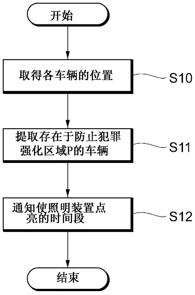
Fig. 4 is a flowchart showing an example of a processing procedure performed by the control device 10 according to the first embodiment. The control device 10 instructs the lighting devices 26 to be turned on during the lighting period by performing the processing procedure shown in fig. 4 among the vehicles 20 managed by the control device 10 in the suburban area R, the vehicles 20 existing in the crime prevention enhancement area P.
First, the acquisition unit 101 acquires position information indicating the current position from each vehicle 20 by communicating with each vehicle 20 managed by the control device 10, and stores the position information in the vehicle management information (S10). Next, the extraction unit 102 acquires the range of the crime prevention enhancement area P from the lighting area information, and extracts one or more vehicles 20 of which the current position acquired in the process of step S10 is within the range of the crime prevention enhancement area P, among the vehicles 20 (S11). Next, the instruction unit 103 acquires the time zone for lighting the lighting device 26 from the lighting time zone information, and notifies the extracted one or more vehicles 20 of information indicating the time zone for lighting the lighting device 26 (S12).
The lighting control unit 203 of the vehicle 20 that has received the information indicating the time period for turning on the lighting device 26 turns on the lighting device 26 provided in the vehicle 20 itself when the lighting start time specified by the information is reached, and turns off the lighting device 26 when the lighting end time specified by the information is reached.
Fig. 5 is a diagram showing a specific example of the vehicle 20. The vehicle 20 shown in fig. 5 is a microminiature mobile body with a passenger number of 1 person. In fig. 5, the illumination device 26-1 shows a specific example of a headlamp provided in the vehicle 20, and the illumination device 26-2 shows a specific example of a crime prevention lamp. Since the crime prevention lamp preferably emits light so as to be conspicuous even when viewed from a distant place, the optical axis may be oriented upward from the horizontal plane. In order to make the light reach far, the optical axis may be automatically changed to a direction in which no blocking object exists near.
Fig. 6 is a diagram showing an example of the system configuration of the illumination system 1 according to the second embodiment. In the first embodiment, each vehicle 20 present in the crime prevention enhancement area P is instructed to light the illumination device 26. However, if the number of vehicles 20 present in the crime prevention enhancement area P is small, the amount of light is insufficient, and therefore, the vehicle is not noticeable from a distant place, and the surroundings cannot be illuminated, and therefore, it is assumed that the crime prevention effect is hardly obtained. In addition, if the illumination device 26 is turned on even though the crime prevention effect is hardly obtained, the battery 28 of the vehicle 20 is unnecessarily consumed, which is inefficient.
Therefore, in the second embodiment, the control device 10 may instruct each vehicle 20 present in the crime prevention enhancement area P to light the illumination device 26 when there are a predetermined number of vehicles 20 in the crime prevention enhancement area P. In addition, when the number of vehicles 20 present in the crime prevention enhancement area P is small, the control device 10 may instruct the vehicles 20 present outside the crime prevention enhancement area P to move into the crime prevention enhancement area P, thereby collecting a predetermined number of vehicles 20 in the crime prevention enhancement area P.
By lighting the lighting devices 26 on a predetermined number or more of the vehicles 20 in the crime prevention enhancement area P, a necessary amount of light can be secured, the surrounding environment can be illuminated clearly and also seen from a distant place, and therefore a high crime prevention effect can be obtained.
The configuration of the control device 10 according to the second embodiment will be described. Points not specifically mentioned may be the same as those in the first embodiment.
The instruction unit 103 has the following functions: when the number of one or more vehicles 20 present in the crime prevention enhancement area P extracted by the extraction unit 102 is equal to or greater than a predetermined number, the one or more extracted vehicles 20 are instructed to light the illumination device 26 for a lighting time period.
In addition, the instruction unit 103 may instruct the vehicle 20 existing outside the crime prevention enhancement area P to move into the crime prevention enhancement area P when the number of the extracted one or more vehicles 20 is smaller than a predetermined number.
Fig. 7 is a flowchart showing an example of a processing procedure performed by the control device 10 according to the second embodiment.
First, the acquisition unit 101 acquires position information indicating the current position from each vehicle 20 by communicating with each vehicle 20 managed by the control device 10 itself, and stores the position information in the vehicle management information (S20). Next, the extraction unit 102 acquires the range of the crime prevention enhancement area P from the lighting area information, and extracts one or more vehicles 20 of which the current position acquired in the process of step S20 is within the range of the crime prevention enhancement area P, among the vehicles 20 (S21).
Next, the instruction unit 103 determines whether or not a predetermined number of vehicles 20 are present in the crime prevention enhancement area P. If so (S22-YES), the process proceeds to step S23, and if not (S22-NO), the process proceeds to step S24.
The instruction unit 103 obtains a time period for lighting the illumination device 26 from the lighting time period information. Further, the instruction unit 103 notifies the acquired information indicating the time zone for lighting the lighting device 26 to the one or more vehicles 20 extracted in the process of step S21 (S23).
The instruction section 103 instructs the vehicle 20 present outside the crime prevention intensification area P to move to the crime prevention intensification area P (S24). The control device 10 repeats the processing of steps S20 to S22 again, and proceeds to the processing of step S23 at the time point when a predetermined number of vehicles 20 are collected in the crime prevention enhancement area P.
The number of vehicles in the crime prevention enhancement area P will be described. As described above, in the second embodiment, in order to secure a necessary amount of light, when a predetermined number or more of vehicles 20 are present in the crime prevention enhancement area P, the lighting devices 26 of the respective vehicles 20 are turned on.
Here, the predetermined number of units may be a number instructed by an administrator of a public institution or the like. Specifically, the receiving unit 100 may receive a predetermined number of inputs to be provided in the crime prevention enhancement area P from a manager or the like, and store the inputs in the lighting area information. In the process of step S22, the instruction unit 103 may access the lighting area information to acquire a predetermined number of devices to be installed in the crime prevention enhancement area P. The manager can arbitrarily designate a predetermined number of the crime prevention enhancement areas P according to the range and the characteristics of the crime prevention enhancement areas P.
The predetermined number of units may be automatically determined by the instruction unit 103 of the control device 10. For example, the number of vehicles 20 to be lit by the lighting device 26 per unit area (for example, 100 square meters) may be set in advance, and the number of vehicles 20 per unit area may be multiplied by the area of the crime prevention enhancement region P. For example, when the area of the crime prevention enhancement area P is 300 square meters, the unit area is 100 square meters, and the number of vehicles 20 per unit area is 10, the predetermined number is 30.
The number of vehicles 20 per unit area may be set to a different value for each crime prevention enhancement area P. For example, for an area designated as the crime prevention enhancement area P due to the occurrence of multiple events, it is considered to increase the number of vehicles 20 per unit area.
A lighting control method in consideration of the remaining battery capacity of each vehicle will be described. It is considered that the vehicle 20 in a state where it can receive power supply from an external power supply at a charging station or the like does not consume the battery 28 even if the lighting device 26 is continuously turned on. However, in the vehicle 20 that does not receive the supply of electric power from the external power supply, if the lighting device 26 is turned on for a long time, the battery 28 is consumed, and there is a possibility that the user cannot use it the next day. Therefore, the control device 10 preferably instructs the lighting of the illumination device 26 in consideration of the remaining battery capacity of each vehicle 20.
The lighting control method 1 will be explained. After executing the processing of step S23 in fig. 7, the control device 10 may monitor the remaining capacity of the battery 28 of each vehicle 20 present in the crime prevention enhancement area P, instruct the vehicle 20 having a small remaining battery capacity to turn off the lighting device 26, and turn on the lighting device 26 of the backup vehicle 20 instead. To achieve this, acquisition unit 101 acquires the remaining battery capacity from each vehicle 20 by communicating with each vehicle 20.
Specifically, the instruction unit 103 monitors the remaining battery capacity of each vehicle 20 acquired by the acquisition unit 101, and instructs the vehicle 20 having the remaining capacity of the battery 28 decreased to the first threshold value or less to turn off the lighting device and the vehicle 20 having the remaining capacity of the battery 28 decreased to the second threshold value or more to turn on the lighting device 26 when there are the vehicle 20 (first vehicle) having the lighting device 26 turned on and the remaining capacity of the battery 28 decreased to the first threshold value or less without turning on the lighting device 26 and the vehicle 20 having the remaining capacity of the battery 28 increased to the second threshold value or more to turn on the lighting device 26 in the crime prevention enhancement area P.
In order to enable such processing, the "predetermined number of vehicles" may include "the vehicle 20 having the remaining capacity of the battery 28 equal to or greater than the second threshold value larger than the first threshold value" as the backup vehicle 20. In the processing of step S23 in fig. 7, the instruction unit 103 may notify each vehicle 20 excluding the vehicle 20 to be secured as a backup from among the plurality of vehicles 20 extracted in the processing of step S21, of information indicating a time zone for which the lighting device 26 is to be turned on.
The lighting control method 2 will be explained. The control device 10 may instruct each vehicle 20 to shift the lighting time period for lighting the lighting device 26 within the range of the time during which each vehicle 20 existing in the crime prevention enhancement area P can light the lighting device 26 in the processing of step S23 in fig. 7. The time during which each vehicle 20 can light the lighting device 26 may be, for example, a time until the remaining capacity of the battery 28 becomes equal to or less than a predetermined threshold (for example, the battery capacity is 1/3 or the like) when the lighting device 26 is continuously lit in a stationary state.
Specifically, first, the acquisition unit 101 acquires the time during which each of the plurality of vehicles 20 present in the crime prevention enhancement area P can light the lighting device 26. The acquisition unit 101 may acquire information (for example, 2 hours or 4 hours) indicating a specific time at which the illumination device 26 can be turned on from the vehicle 20, or may acquire information indicating an indirect time at which the illumination device 26 can be turned on, such as a remaining battery capacity, from the vehicle 20. In the latter case, the time at which the vehicle 20 can turn on the illumination device 26 may be calculated using a calculation formula that is set in advance to convert the battery remaining capacity into the time at which the illumination device 26 can be turned on.
Next, the instruction unit 103 determines a time period for instructing each vehicle to light the illumination device 26 for each vehicle, and instructs each vehicle to light the illumination device in the determined time period for each vehicle 20, based on the time at which each vehicle 20 can light the illumination device 26 and the lighting time period specified by the lighting time period information, at least within the range of the time at which each vehicle 20 can light the illumination device 26.
For example, when the vehicle 20A can turn on the illumination device 26 for 4 hours and the vehicle 20B can turn on the illumination device 26 for 3 hours, it is assumed that the lighting time zone specified by the lighting time zone information is from 10 o 'clock at night to 5 o' clock at the next morning. In this case, the control device 10 may instruct the vehicle 20A to turn on the illumination device 26 during 4 hours from night 10 to next day 2, and instruct the vehicle 20B to turn on the illumination device 26 during 3 hours from next day 2 to morning 5.
Further, the instruction unit 103 may determine the time period in which each vehicle 20 lights the lighting device 26, based on the time at which the vehicle 20 can light the lighting device 26 and the lighting time period specified by the lighting time period information, such that the time period in which each vehicle lights the lighting device 26 is dispersed over the entire lighting time period at least within the range of the time at which each vehicle 20 can light the lighting device 26.
In the first and second embodiments, the control device 10 controls the lighting and the extinction of the lighting device 26 of each vehicle 20, but in the third embodiment, each vehicle 20 controls the lighting and the extinction of its own lighting device 26.
Fig. 8 is a flowchart showing a processing procedure performed by the vehicle 20 according to the third embodiment. It is assumed that each vehicle 20 holds the lighting area information and the lighting time zone information described in the first and second embodiments in the memory 22. It is assumed that the vehicle 20 repeats the processing from step S30 to step S33 at predetermined intervals (for example, at 1-minute intervals, 5-minute intervals, and the like).
First, the detection unit 200 acquires the current position of the vehicle 20 itself using the GPS receiving device 25 (S30). Next, the acquisition unit 202 acquires the range of the crime prevention enhancement area P from the lighting area information. Next, the lighting control unit 203 determines whether or not the current position of the vehicle 20 itself is within the crime prevention enhancement area P (S31). If the current position is not in the crime prevention enhancement area P (S31 — no), the process is ended, and if the current position is in the crime prevention enhancement area P (S31-yes), the process proceeds to step S32.
Next, the acquisition unit 202 acquires the time zone for lighting the lighting device 26 from the lighting time zone information. Next, the lighting control unit 203 determines whether or not the current time is included in the time period for lighting the lighting device 26 (S32). When the current time is included in the time period for lighting the lighting device 26, the lighting control unit 203 lights the lighting device 26 (S33). If the current time is not included in the time period for lighting the lighting device 26, the process ends. Further, illumination control unit 203 may turn on illumination device 26 when the remaining capacity of the battery mounted on vehicle 20 is equal to or greater than a predetermined remaining capacity or when vehicle 20 is in a state of being supplied with electric power from an external power supply.
According to the embodiments described above, in the crime prevention enhancement area P, the illumination device 26 provided in the vehicle 20 can be turned on, and thus, a crime prevention measure can be taken for a region using the vehicle 20.
In addition, according to the second embodiment, since the lighting devices 26 are turned on by a predetermined number or more of the vehicles 20 in the crime prevention enhancement area P, a necessary amount of light can be secured, and moreover, the surrounding environment can be illuminated clearly and clearly as seen from a distant place, so that a high crime prevention effect can be obtained. Further, it is possible to instruct the lighting and turning-off of the lighting device 26 while taking into consideration the remaining battery capacity of each vehicle 20, and it is possible to perform control so that the battery of the vehicle 20 does not run out of power.
In addition, according to the third embodiment, the vehicle 20 controls the lighting of the lighting device 26 of itself, so that the lighting and the lighting of the lighting device 26 can be controlled even in an area where communication with the control device 10 is impossible. This enables the control device 10 to take regional crime prevention measures even in an area where communication with the vehicle 20 is impossible.
The embodiments described above are for the purpose of facilitating understanding of the present invention, and are not intended to limit the embodiments for explaining the present invention. The flowcharts, sequences, elements included in the embodiments, and the arrangement, materials, conditions, shapes, sizes, and the like of the elements are not limited to those illustrated in the embodiments, and may be appropriately modified. In addition, the configurations shown in different embodiments may be partially replaced or combined with each other.
For example, in various embodiments, the control unit 10 may manage any area, rather than managing suburban R. Similarly, the control device 10 is limited to the security enhanced area P. For example, instead of the crime prevention enhancement area P, the illumination in an area such as a sports venue where illumination is frequently used may be managed. That is, the crime prevention enhancement area P, the event venue, and the like may be referred to as "an area in which the lighting device is turned on".
In each embodiment, the vehicle 20 is not limited to a microminiature mobile unit. For example, any vehicle may be used as long as the vehicle 20 is mounted with the lighting device 26.
The processes executed by the control device 10 in the embodiments may be executed by the vehicle 20 instead of the control device 10. For example, the present invention can be implemented by any one of the vehicles 20 existing in the suburban area R executing the same processing as the control apparatus 10. In this case, the control device 10 and the vehicle 20 may also be referred to as "information processing devices".