CN111085040A - Oil purification system and method - Google Patents
Oil purification system and method Download PDFInfo
- Publication number
- CN111085040A CN111085040A CN202010005203.5A CN202010005203A CN111085040A CN 111085040 A CN111085040 A CN 111085040A CN 202010005203 A CN202010005203 A CN 202010005203A CN 111085040 A CN111085040 A CN 111085040A
- Authority
- CN
- China
- Prior art keywords
- oil
- purifier
- bin
- grading
- layer
- Prior art date
- Legal status (The legal status is an assumption and is not a legal conclusion. Google has not performed a legal analysis and makes no representation as to the accuracy of the status listed.)
- Granted
Links
Images


Classifications
-
- B—PERFORMING OPERATIONS; TRANSPORTING
- B01—PHYSICAL OR CHEMICAL PROCESSES OR APPARATUS IN GENERAL
- B01D—SEPARATION
- B01D36/00—Filter circuits or combinations of filters with other separating devices
Landscapes
- Chemical & Material Sciences (AREA)
- Chemical Kinetics & Catalysis (AREA)
- Filtration Of Liquid (AREA)
Abstract
The invention belongs to the technical field of oil product treatment devices, and particularly relates to an oil purifying system and method. The oil purification system disclosed by the invention is characterized in that an oil product to be treated is classified by utilizing the classification device, the oil product is correspondingly injected into the vacuum oil purification device or the pressure oil purification device according to the characteristics of the oil product at different grades, the pressure oil purification device and the vacuum oil purification device are organically combined, the technological characteristics of the pressure oil purification device and the vacuum oil purification device are respectively and fully excavated and utilized, the pressure oil purification device and the vacuum oil purification device exert a synergistic effect, and two-stage treatment is carried out, wherein the first stage mainly comprises targeted treatment, and the second stage comprises integral treatment, which has respective emphasis and pertinence, so that the oil product treatment effect is remarkably improved, the oil product treatment efficiency is effectively improved, and the oil product purification system has great popularization value and wide application prospect.
Description
Technical Field
The invention belongs to the technical field of oil product treatment devices, and particularly relates to an oil purifying system and method.
Background
The oil purifier is also called as an oil filter, plays a great role in purifying and regenerating various industrial oil products with deteriorated pollution, and can effectively remove pollutants in the oil products such as: the oil product has high kinematic viscosity, flash point and emulsibility, and can restore its service performance to near or up to the standard of new oil.
At present, pressure oil purification devices which are good at removing solid impurities and vacuum oil purification devices which are good at removing gas and moisture are most widely applied, but most of conventional technical schemes are used independently, equipment oil products really contain various impurities such as solid impurities, gas impurities, moisture and the like in the using process, and the conventional technology cannot meet the requirement of high-efficiency oil purification. Although there is also a separate technical scheme to combine the pressure oil purifier with the vacuum oil purifier, the combination is only mechanical, and usually all oil products pass through the pressure oil purifier and the vacuum oil purifier successively, and the technological characteristics are not fully exerted according to the characteristics of different oil purifiers, and even the two oil purifiers do not exert the synergistic effect, so that the oil purification efficiency and the oil purification effect are still difficult to be expected.
Disclosure of Invention
The invention aims to overcome the defects of the prior art, provides an oil purifying system which organically combines a pressure oil purifier and a vacuum oil purifier, fully excavates and exerts the process potential of different oil purifiers, so that the two oil purifiers generate a synergistic effect, the oil purifying efficiency and the oil purifying effect are obviously improved, and provides an oil purifying method.
In order to achieve the purpose of the invention, the technical scheme adopted by the invention is as follows: the utility model provides an oil purification system, includes and carries out hierarchical grading plant with treating the oil body of purifying, grading plant's lateral wall is equipped with a plurality of oil drain ports that are used for discharging different grades of oil bodies, each the oil drain port communicates with multistage vacuum oil purification device and/or multistage pressure oil purification device respectively. The oil to be treated is graded by the grading device, and is correspondingly injected into the vacuum oil purifier or the pressure oil purifier according to the characteristics of the oil at different grades, so that the technical characteristics of different oil purifiers are fully utilized and excavated, the synergistic effect is exerted, the oil treatment effect is obviously improved, and the oil treatment efficiency is more effectively improved.
Furthermore, the grading device comprises a cylindrical grading bin, a bin port capable of receiving an oil body of an oil inlet pipe is arranged at the top of the grading bin, four oil discharge ports are arranged on the side wall of the grading bin at different height positions, and the side wall of the grading bin is respectively provided with an oil discharge port A, an oil discharge port B, an oil discharge port C and an oil discharge port D from bottom to top; and the side wall of the grading bin is provided with a stirring mechanism capable of enabling oil in the bin body to move. Through stirring, the back layering of stewing, divide into the oil of A layer that contains solid impurity much, B layer oil that contains water impurity much, C layer oil that impurity content is few, D layer oil that contains gas impurity much with the oil, the oil of different grades is discharged from the oil drain port of not co-altitude, can carry out targeted follow-up processing, and optimization treatment effect improves the treatment effeciency.
Further, A oil drain port and one-level pressure oil purifier input intercommunication, B oil drain port, D oil drain port and one-level vacuum oil purifier input intercommunication, C oil drain port, one-level pressure oil purifier output, one-level vacuum oil purifier output and second grade pressure oil purifier input intercommunication, second grade pressure oil purifier output and second grade vacuum oil purifier input intercommunication, second grade vacuum oil purifier output and play oil pipe intercommunication. The oil with different characteristics can be delivered to the first-level oil purifier with corresponding speciality for treatment, the pertinence is strong, the relative quantity is small, the natural effect is good, the efficiency is high, the secondary treatment is carried out through the second-level pressure oil purifier and the second-level vacuum oil purifier together, the load of the device is low, the impact is small, and the oil outlet quality can be guaranteed to be stable and reach the standard.
Furthermore, the stirring mechanism comprises a rotatable inner ring positioned on the inner side wall of the grading bin, an outwardly-protruding abdicating ring is arranged at the position of the side wall of the grading bin, which corresponds to the inner ring, a controllable-rotating outer ring is arranged at the position of the outer side wall of the grading bin, which corresponds to the abdicating ring, the cross section of the outer ring is in a C shape with an inward opening, and the opening is used for accommodating the abdicating ring; the outer ring can drive the inner ring to rotate; the medial surface of inner ring is equipped with a plurality of stirring pieces, the stirring piece is the circumference equipartition. The secondary pollution caused by impurities brought in the purification process can be avoided, the burden of the vacuum oil purifier and the pressure oil purifier is further reduced, the purification effect and efficiency are improved, and in addition, the leakage of oil bodies from the transmission holes is fundamentally avoided.
Furthermore, a plurality of first convex edges are vertically arranged on the outer side surface of the inner ring, the first convex edges are uniformly distributed on the circumference, and first magnetic blocks are arranged on the side surfaces of the first convex edges in the same direction; the abdicating ring is used for accommodating the first convex rib and is made of a non-magnetic material; a plurality of second convex ridges are vertically arranged on the inner side surface of the bottom of the opening of the outer ring, the second convex ridges are uniformly distributed on the circumference of each second convex ridge, and second magnetic blocks are arranged on the side surfaces of the second convex ridges in the same direction; the second magnetic block and the first magnetic block face opposite to each other and have the same magnetic pole. The outer ring action is transmitted to the inner ring through magnetic force, so that secondary pollution caused by impurities brought in the purification process is avoided, the burden of the vacuum oil purifier and the pressure oil purifier is further reduced, the purification effect and efficiency are improved, and the leakage of oil bodies from the transmission holes is fundamentally avoided.
Further, advance the oil pipe and have downward buckling section, the buckling section is equipped with rough filtering device, rough filtering device is including setting up the shunt tubes at advancing the oil pipe lateral wall, the upper and lower both ends of shunt tubes communicate with each other with advancing oil pipe before buckling, back position respectively, be equipped with the filter bag in the shunt tubes, advance oil pipe and be close to shunt tubes upper end open-ended position and be equipped with the filter screen, the filter screen can make the solid impurity in advancing oil pipe flow direction shunt tubes along with the oil body. Set up coarse filter equipment and can filter thick solid impurity in advance, effectively reduce pressure oil purifier's load, also can reduce oil pipeline and oil purifier by a wide margin and be blockked up and the possibility of scraping, effectively reduce the maintenance degree of difficulty and maintenance frequency.
Furthermore, the pipe diameter of the shunt pipe is gradually reduced from top to bottom, the filter bag is detachably connected with the shunt pipe, a bag taking opening is formed in the side wall of the oil inlet pipe, and the bag taking opening is opposite to an opening, formed in the side wall of the oil inlet pipe, of the upper end of the shunt pipe. After the filter bag is used for a period of time, the bag opening is taken for replacement, the filtering effect is effectively guaranteed, and the oil body is prevented from being blocked by the shunt tubes.
Furthermore, the one end that advances oil pipe and be close to the oil feed storehouse is equipped with the lock valve advance on the oil pipe, the lock valve one side of keeping away from the oil feed storehouse is equipped with the buffer memory chamber. When one grading bin is full, the other grading bin can be replaced, in the replacement process, only the locking valve needs to be closed, the oil body of the oil inlet pipe can be continuously filled and only temporarily stored in the buffer cavity, the locking valve can be opened after the next grading bin is in place, the oil body can flow into the grading bin at an accelerated speed, the oil inlet end of the oil inlet pipe in the whole process does not need to stop working, the time consumption for restarting and the energy consumption for pressurizing are saved, the efficiency is improved, and the cost is reduced.
The invention also provides an oil purification method, which utilizes the oil purification system and comprises the following steps:
(S1) injecting the oil to be cleaned into the grading device through the oil inlet pipe;
(S2) the oil to be cleaned enters a grading device and then is layered, and the oil to be cleaned sequentially comprises layer A oil containing more solid impurities, layer B oil containing more water impurities, layer C oil containing less impurities and layer D oil containing more gas impurities from bottom to top;
(S3) discharging oil in the grading device from top to bottom, collecting oil in a layer D after being discharged and oil in a layer B after being discharged, collecting oil in a layer C after being discharged and oil in the layer C for later use, discharging the oil in the layer A and collecting the oil in the layer D and then feeding the oil in the layer A into a first-level vacuum oil purifier, and discharging the oil in the layer A and then feeding the oil in the layer A into a first-level pressure oil purifier;
(S4) the oil processed by the first-stage vacuum oil purifier, the oil processed by the first-stage pressure oil purifier and the layer C oil flowing out of the grading device enter a second-stage pressure oil purifier 7;
(S5) the oil treated by the secondary pressure oil purifier enters a secondary vacuum oil purifier;
(S6) the oil product treated by the secondary vacuum oil purifier is discharged out of the oil purifying system through an oil outlet pipe after being inspected to reach the standard. The method comprises the steps of classifying oil to be treated, correspondingly injecting the oil to be treated into a vacuum oil purifier or a pressure oil purifier according to the characteristics of the oil at different grades, fully excavating and utilizing the technological characteristics of the pressure oil purifier and the vacuum oil purifier respectively to enable the pressure oil purifier and the vacuum oil purifier to exert synergistic effect, and carrying out two-stage treatment, wherein the first stage mainly comprises targeted treatment, and the second stage comprises integral treatment, which is emphasized and targeted, so that the oil treatment effect is remarkably improved, and the oil treatment efficiency is effectively improved.
Further, in the step (S1), before the oil to be cleaned is injected into the grading device, coarse filtration is performed. Set up the coarse filtration process, can filter thick solid impurity in advance, effectively reduce pressure oil purifier's load, also can reduce oil pipeline and oil purifier by a wide margin and blockked up and the possibility of scraping, effectively reduce the maintenance degree of difficulty and maintenance frequency.
The invention has the following beneficial effects:
the oil purification system disclosed by the invention is characterized in that an oil product to be treated is classified by utilizing the classification device, the oil product is correspondingly injected into the vacuum oil purification device or the pressure oil purification device according to the characteristics of the oil product at different grades, the pressure oil purification device and the vacuum oil purification device are organically combined, the technological characteristics of the pressure oil purification device and the vacuum oil purification device are respectively and fully excavated and utilized, the pressure oil purification device and the vacuum oil purification device exert a synergistic effect, and two-stage treatment is carried out, wherein the first stage mainly comprises targeted treatment, and the second stage comprises integral treatment, which has respective emphasis and pertinence, so that the oil product treatment effect is remarkably improved, the oil product treatment efficiency is effectively improved, and the oil product purification system has great popularization value and wide application prospect.
Drawings
FIG. 1 is an overall schematic of an oil purification system according to the present invention;
FIG. 2 is a front cut-away view of a first embodiment of a grading apparatus of the present invention;
FIG. 3 is an enlarged view taken at A of FIG. 2 according to the present invention;
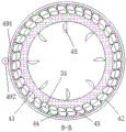
FIG. 4 is a schematic cross-sectional view taken at B-B of FIG. 2 according to the present invention
FIG. 5 is a top view of a second embodiment of a grading device of the present invention;
FIG. 6 is a schematic front view of the hidden front-to-back directional staging bin of FIG. 5 in accordance with the present invention;
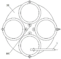
FIG. 7 is a plan view of a third embodiment of the classifying device according to the present invention in a state where the stirring mechanism is operated;
FIG. 8 is a schematic front view of the hidden front-to-back directional staging bin of FIG. 7 in accordance with the present invention;
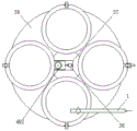
FIG. 9 is a plan view of a third embodiment of the classifying device according to the present invention in a state where the stirring mechanism is stopped;
FIG. 10 is a schematic front view of the hidden front-to-back direction staged bin of FIG. 9 according to the present invention.
Detailed Description
Referring to fig. 1 to 10, the present invention shows an oil purification system, which includes a classification device 3 capable of classifying oil bodies to be purified, wherein a plurality of oil discharge ports 33 for discharging oil bodies of different levels are disposed on a side wall of the classification device 3, and each oil discharge port 33 is respectively communicated with a multi-stage vacuum oil purification device and/or a multi-stage pressure oil purification device. It can be understood that the oil to be treated is classified by the classification device 3, and is correspondingly injected into the vacuum oil purifier or the pressure oil purifier according to the characteristics of the oil at different grades, so that the technological characteristics of different oil purifiers are fully utilized and excavated, a synergistic effect is exerted, the oil treatment effect is obviously improved, and the oil treatment efficiency is more effectively improved.
Further, the grading device 3 comprises a cylindrical grading bin 31, a bin port 32 capable of receiving the oil body of the oil inlet pipe 1 is arranged at the top of the grading bin 31, four oil discharge ports 33 are arranged at different height positions on the side wall of the grading bin 31, and the oil discharge ports are an oil discharge port A331, an oil discharge port B332, an oil discharge port C333 and an oil discharge port D334 from bottom to top respectively; the side wall of the grading bin 31 is provided with a stirring mechanism 4 which can move oil in the bin body. It can be understood that the oil product is divided into a layer A oil containing more solid impurities, a layer B oil containing more water impurities, a layer C oil containing less impurities and a layer D oil containing more gas impurities by stirring and standing for layering, the oils of different levels are discharged from oil outlets at different heights, targeted subsequent treatment can be carried out, the treatment effect is optimized, and the treatment efficiency is improved. In order to facilitate the oil body to be completely discharged, a slide carriage 34 is arranged at the bottom of the grading bin 31, and the surface of the slide carriage 34 extends downwards towards the oil outlet 33 from the inner side wall opposite to the oil outlet 33.
Further, an oil discharge port A331 is communicated with an input end of a first-stage pressure oil purifier 6, an oil discharge port B332, an oil discharge port D334 are communicated with an input end of a first-stage vacuum oil purifier 5, an oil discharge port C333, an output end of the first-stage pressure oil purifier 6, an output end of the first-stage vacuum oil purifier 5 is communicated with an input end of a second-stage pressure oil purifier 7, an output end of the second-stage pressure oil purifier 7 is communicated with an input end of a second-stage vacuum oil purifier 8, and an output end of the second-stage vacuum oil purifier 8 is communicated with an oil outlet. It can be understood that the oil of layer A containing more solid impurities is firstly injected into the first-stage pressure oil purifier 6 to remove most of the solid impurities, the oil of layer B containing more solid impurities and the oil of layer D containing more gas impurities are firstly injected into the first-stage vacuum oil purifier 5 to remove most of the water and gas impurities, then the oil treated by the first-stage pressure oil purifier 6, the oil treated by the first-stage vacuum oil purifier 5 and the oil of layer C containing less impurities are injected into the second-stage pressure oil purifier 7 together to remove the rest of the solid impurities, and finally the oil treated by the second-stage pressure oil purifier 7 is injected into the second-stage vacuum oil purifier 8 to remove the rest of the water and gas impurities, so that the oil products with different characteristics are firstly delivered to the first-stage oil purifier with corresponding characteristics for treatment, the pertinence, the relative quantity is small, the natural effect is good, the efficiency is high, and then the oil products are sequentially treated by the second-stage pressure oil purifier 7 together, The secondary vacuum oil purifier 8 performs secondary treatment, the load of the device is low, the impact is small, and the oil outlet quality can be ensured to reach the standard stably. Wherein the unit handling capacity of the secondary vacuum oil purifier 8 is greater than that of the primary vacuum oil purifier 5; the unit handling capacity of the secondary pressure oil purifier 7 is greater than that of the primary pressure oil purifier 6, and the primary oil purifier performs targeted treatment on oil products with heavy pollution, and the total amount of oil bodies with heavy pollution in a grading way is smaller, so that the primary oil purifier is selected to be a model with a smaller specification; the secondary oil purifier is used for integrally treating oil products with light pollution and oil bodies treated by the primary oil purifier, and the total amount to be treated is large, so that the secondary oil purifier is selected from models with large specifications.
Further, the stirring mechanism 4 comprises a rotatable inner ring 41 positioned on the inner side wall of the grading bin 31, an outwardly convex abdicating ring 35 is arranged at the position of the side wall of the grading bin 31 corresponding to the inner ring 41, a controllable rotatable outer ring 42 is arranged at the position of the outer side wall of the grading bin 31 corresponding to the abdicating ring 35, the cross section of the outer ring 42 is in a C shape with an inward opening for accommodating the abdicating ring 35; the outer ring 42 may drive the inner ring 41 to rotate; the inner side surface of the inner ring 41 is provided with a plurality of stirring sheets 48, and the stirring sheets 48 are uniformly distributed in the circumference. It can be understood that the outer ring 42 drives the inner ring 41 to rotate, the inner ring 41 drives the stirring sheet 48 to rotate, so that the oil body in the grading bin 31 is stirred, solid impurities sink to the bottom, water with high density is in the lower layer, gas with low density is left in the upper layer, the solid impurities can be discharged and injected into a corresponding oil purifier for subsequent treatment after standing, the outer ring 42 of the driving end and the inner ring 41 of the driven end do not need to be in direct contact, so that holes are prevented from being additionally formed in the bin body, and only necessary bin openings 32 and oil discharge openings 33 are reserved in the whole grading bin 31, so that secondary pollution caused by impurities brought in during the purification process can be avoided, the burden of the vacuum oil purifier and the pressure oil purifier is reduced, the purification effect and efficiency are improved, and in addition, the leakage of the oil body from the transmission holes is fundamentally avoided.
Further, a plurality of first protruding ribs are vertically arranged on the outer side surface of the inner ring 41, the first protruding ribs are uniformly distributed on the circumference, and first magnetic blocks 43 are arranged on the side surfaces of the first protruding ribs in the same direction; the avoiding ring 35 is used for accommodating the first rib, and the avoiding ring 35 is made of a non-magnetic material; a plurality of second convex ribs are vertically arranged on the inner side surface of the bottom of the opening of the outer ring 42, the second convex ribs are uniformly distributed on the circumference, and second magnetic blocks 44 are arranged on the side surfaces of the second convex ribs in the same direction; the second magnetic block 44 and the first magnetic block 43 face each other and have the same magnetic pole. It can be understood that when the outer ring 42 is controlled to rotate, the second magnet 44 on the second rib is close to the first magnet 43, the first magnet 43 is driven by the repulsion force to drive the inner ring 41 to rotate, the outer ring 42 is transferred to the inner ring 41 through magnetic force, secondary pollution caused by impurities brought in during the purification process is avoided, the burden of the vacuum oil purifier and the pressure oil purifier is further reduced, the purification effect and efficiency are improved, and the oil body leakage from the transmission hole is fundamentally avoided. The controlled rotation of the outer ring 42 may adopt various driving modes such as gears, worms, belts, synchronous belts, etc., for example, a gear ring 491 is disposed on the outer side surface of the outer ring 42, the gear ring 491 is adapted to engage with a driving gear 492, the gear 492 is fixedly connected with an output end of the motor 493, and an appropriate driving mechanism may be reasonably selected according to requirements and conditions in specific implementation. The letting bit ring 35 is made of a non-magnetic material, which means that the letting bit ring 35 does not hinder the magnetic field of the second magnetic block 44 from acting on the first magnetic block 43, and specifically, a common non-ferrous metal or engineering plastic can be selected.
Referring to fig. 2 to 4, the connection between the inner ring 41 and the outer ring 42 and the classifying bin 31 will be explained: the bottom surface of the inner ring 41 is provided with a first supporting block 451, the side surface of the first supporting block 451 is fixedly connected with the inner side wall of the grading bin 31, and the top surface of the first supporting block 451 is slidably connected with the bottom surface of the inner ring 41; the bottom surface of the outer ring 42 is provided with a second supporting block 452, the side surface of the second supporting block 452 is fixedly connected with the outer side wall of the grading bin 31, and the top surface of the second supporting block 452 is slidably connected with the bottom surface of the outer ring 42.
A plurality of first balls 461 which are uniformly distributed are arranged between the top surface of the first support block 451 and the bottom surface of the inner ring 41, a first holding frame 471 for maintaining the distance between the balls is arranged outside the plurality of first balls 461, and rolling grooves are arranged at the positions of the top surface of the second support block 452 and the bottom surface of the inner ring 41 corresponding to the first balls 461; a plurality of second balls 462 which are uniformly distributed are arranged between the top surface of the second support block 452 and the bottom surface of the outer ring 42, a second retainer 472 for maintaining the distance between the plurality of second balls 462 is arranged outside the plurality of second balls 462, and rolling grooves are arranged at the positions of the top surface of the second support block 452 and the bottom surface of the outer ring 42 corresponding to the second balls 462.
The top surface of the inner ring 41 is provided with a first pressing block 453, the side surface of the first pressing block 453 is fixedly connected with the inner side wall of the grading bin 31, and the bottom surface of the first pressing block 453 is in sliding connection with the top surface of the inner ring 41; the top surface of the outer ring 42 is provided with a second pressing block 454, the side surface of the second pressing block 454 is fixedly connected with the outer side wall of the grading bin 31, and the bottom surface of the second pressing block 454 is connected with the top surface of the outer ring 42 in a sliding manner.
A plurality of third balls 463 which are uniformly distributed are arranged between the bottom surface of the first pressing block 453 and the top surface of the inner ring 41, a third retainer 473 for maintaining the distance between the balls is arranged outside the plurality of third balls 463, and rolling grooves are formed in the positions, corresponding to the third balls 463, of the bottom surface of the first pressing block 453 and the top surface of the inner ring 41; a plurality of uniformly arranged fourth balls 464 are arranged between the bottom surface of the second press block 454 and the top surface of the outer ring 42, a fourth retainer 474 for maintaining the distance between the balls is arranged outside the plurality of fourth balls 464, and rolling grooves are formed in the positions of the bottom surface of the second press block 454 and the top surface of the outer ring 42 corresponding to the fourth balls 464.
It should be understood that the above structure is only one connection way adopted by the inventor in the implementation, and the suitable connection mechanism of the inner ring 41, the outer ring 42 and the classifying bin 31 can be reasonably selected according to the requirements, conditions and other factors in the implementation.
Further, the oil inlet pipe 1 is provided with a downward bending section, the bending section is provided with a rough filtering device 2, the rough filtering device 2 comprises a shunt pipe 21 arranged on the side wall of the oil inlet pipe 1, the upper end and the lower end of the shunt pipe 21 are respectively communicated with the front position and the rear position of the oil inlet pipe 1 before bending, a filter bag 22 is arranged in the shunt pipe 21, a filter screen 23 is arranged at the position of the oil inlet pipe 1 close to the opening at the upper end of the shunt pipe 21, and the filter screen 23 can enable solid impurities in the oil inlet pipe 1 to flow to the shunt pipe. It can be understood that setting up coarse filter 2 can be with the filtering in advance of thick solid impurity, effectively reducing pressure oil purifier's load, also can reduce oil pipeline and oil purifier by a wide margin and be blockked up and the possibility of scraping, effectively reduce the maintenance degree of difficulty and maintenance frequency.
Further, the pipe diameter of the shunt pipe 21 is gradually reduced from top to bottom, the filter bag 22 is detachably connected with the shunt pipe 21, a bag taking opening 24 is formed in the side wall of the oil inlet pipe 1, and the bag taking opening 24 is opposite to an opening in the side wall of the oil inlet pipe 1 at the upper end of the shunt pipe 21. It can be understood that after the filter bag 22 is used for a period of time, the filter bag opening 24 is replaced, so that the filtering effect is effectively ensured, and the oil body is prevented from being blocked at the shunt pipe 21.
Further, the one end that advances oil pipe 1 and be close to the oil feed bin is equipped with lock valve 11, advances oil pipe 1 and on one side that lock valve 11 kept away from the oil feed bin be equipped with buffer memory chamber 12. It can be understood that, another grading bin 31 can be replaced after one grading bin 31 is full, in the replacement process, only the locking valve 11 needs to be closed, the oil body of the oil inlet pipe 1 can be continuously filled and only temporarily stored in the buffer cavity 12, the locking valve 11 can be opened after the next grading bin 31 is in place, the oil body 1 can flow into the grading bin 31 at an accelerated speed, the oil inlet end of the oil inlet pipe 1 does not need to stop working in the whole process, the time consumption for restarting and the energy consumption for pressurization are saved, the efficiency is improved, and the cost is reduced.
It should be noted that fig. 1 shows a situation that each oil outlet 33 of the classifying bin 31 is directly connected to a corresponding oil pipeline, at this time, intermittent operation can be performed, after oil is discharged, oil can be fed to start the next round of processing, the classifying bin 31 can be replaced after the locking valve 11 and the buffer chamber 12 are arranged, the oil inlet end does not need to stop working, time consumed by restarting and energy consumed by pressurizing are saved, efficiency is improved, cost is reduced, and two specific implementation modes are shown below.
Referring to fig. 5 to 6, a second embodiment of the classifying device is shown, wherein a plurality of classifying bins 31 are provided, a plurality of classifying bins 31 are uniformly distributed on the circumference of a turntable 38 which can be controlled to rotate, a base 39 is arranged at the bottom of the turntable 38, and a motive power mechanism which can drive the turntable 38 to rotate is arranged in the base 39. The classifying bin 31 is four, and is an oil inlet bin, a stirring bin, a standing bin and an oil discharging bin in sequence along the circumferential direction, wherein the oil inlet bin is positioned below the oil inlet pipe 1, and four oil discharging hoppers are respectively matched with the four lower parts of the oil discharging ports 33 of the oil discharging bin. Obviously, the so-called "oil inlet bin, stirring bin, standing bin, and oil discharging bin" is based on the function that the oil inlet bin is located below the oil inlet pipe 1, after the oil inlet bin is filled, the rotary table 38 rotates to transfer the oil discharging bin with the discharged oil to the position below the oil inlet pipe 1, the oil is continuously filled, the original oil inlet bin is stirred, then the oil inlet bin is placed still, finally the oil is discharged, and a cycle is ended, so that the cycle is completed. The number of the motors 493 is four, the motors are fixedly connected with the outer side walls of the oil inlet bin, the stirring bin, the standing bin and the oil discharge bin respectively, the output ends of the motors are connected with the gear 492, and the outer ring 42 is driven to rotate through inner core transmission. In addition, the rotary table 38 can be set to be a cone (both cone and pyramid) with high middle and low periphery, the bottom of the corresponding grading bin 31 is made into a matched shape, a slide carriage 34 is not needed, the effect of facilitating the exhaustion of oil bodies can be achieved, the position of the oil receiving hopper is relatively fixed and is always located at the position of the oil discharging bin, and the oil bodies discharged from the oil discharging bin are received.
Referring to fig. 7 to 8, a third embodiment of the grading device is shown, a fixed platform 37 is provided at the middle of the top surface of the base 39, the fixed platform 37 extends vertically upwards through the turntable 38, and a telescopic assembly 36 is provided at the top surface of the fixed platform 37, wherein the telescopic assembly 36 can enable the gear 492 to approach or separate from the gear rim 491 of the stirring bin. It can be understood that the improvement is made on the basis of the second embodiment of the grading device, so that only one motor 493 is needed to be arranged, the motor 493 on the oil inlet bin, the standing bin and the oil discharge bin is prevented from being idle for a long time, the work efficiency of the system is improved, and meanwhile, the early investment cost, the later operation cost and the maintenance pressure are also reduced. The telescopic assembly 36 includes a telescopic cylinder estimated from the top surface of the fixed table 37, and a slide plate fixedly connected to the bottom of the motor 493 and slidably connected to the top of the fixed table 37, one end of the slide plate is fixedly connected to an output end of the telescopic cylinder, and the telescopic cylinder may be an air cylinder or an electric cylinder.
The invention also provides an oil purification method, which utilizes the oil purification system and comprises the following steps:
(S1) injecting the oil to be cleaned into the grading device 3 through the oil inlet pipe 1;
(S2) the oil to be cleaned enters the grading device 3 and then is layered, and the oil to be cleaned sequentially comprises layer A oil containing more solid impurities, layer B oil containing more water impurities, layer C oil containing less impurities and layer D oil containing more gas impurities from bottom to top;
(S3) discharging oil in the grading device 3 from top to bottom, collecting oil in a layer D after discharging the oil, collecting the oil in a layer B after discharging the oil in a layer C for later use, discharging the oil in the layer B, collecting the oil in the layer B with the oil in the layer D, and then feeding the oil in the layer B into a first-level vacuum oil purifier 5, and discharging the oil in the layer A and then feeding the oil in the layer A into a first-level pressure oil purifier 6;
(S4) the oil processed by the first vacuum oil purifier 5, the oil processed by the first pressure oil purifier 6 and the layer C oil flowing out of the grading device 3 enter the second pressure oil purifier 7;
(S5) the oil treated by the secondary pressure oil purifier 7 enters a secondary vacuum oil purifier 8;
(S6) the oil product treated by the secondary vacuum oil purifier 8 is led out of the oil purifying system through the oil outlet pipe 9 after being inspected to reach the standard.
Firstly, oil to be treated is graded by a grading device 3 and is divided into layer A oil containing more solid impurities, layer B oil containing more water impurities, layer C oil containing less impurities and layer D oil containing more gas impurities, and the oil is correspondingly injected into a vacuum oil purifier or a pressure oil purifier according to the characteristics of oil products of different grades, namely, the layer B oil containing more water impurities and the layer D oil containing more gas impurities are firstly injected into a first-stage vacuum oil purifier 5 to remove most of water and gas impurities, then the oil treated by the first-stage pressure oil purifier 6, the oil treated by the first-stage vacuum oil purifier 5 and the layer C oil containing less impurities are injected into a second-stage pressure oil purifier 7 together to remove residual solid impurities, and finally the oil treated by the second-stage pressure oil purifier 7 is injected into a second-stage vacuum oil purifier 8 to remove residual water and gas impurities, so that the pressure oil purifier, the water purifier and the gas impurities are fully excavated and utilized respectively, The vacuum oil purifier has the technical characteristics that the vacuum oil purifier and the vacuum oil purifier can exert synergistic effect, and two-stage treatment is carried out, wherein the first stage mainly comprises targeted treatment, and the second stage comprises integral treatment, which are respectively emphasized and purposeful, so that the oil product treatment effect is obviously improved, and the oil product treatment efficiency is more effectively improved. Wherein, the treatment effect of the second-stage vacuum oil purifier 8 is superior to that of the first-stage vacuum oil purifier 5; the treatment effect of second grade pressure purifier 7 is superior to the treatment effect of first grade pressure purifier 6, because the one-level purifier carries out the pertinence to polluting heavier oil and the oil body after the one-level purifier is handled and handle, need correspond and get rid of most impurity in the oil body, consequently, the one-level purifier chooses the model that design load is bigger for use, and the second grade purifier carries out the wholeness to polluting lighter oil and handles, need get rid of a small amount of impurity that the one-level purifier did not get rid of, and guarantee that it is up to standard to go out oil quality stability, consequently, the good model of purifying effect is chooseed for use to the second grade purifier.
Further, in the step (S1), before the oil to be cleaned is injected into the classifying device 3, coarse filtration is performed. Set up the coarse filtration process, can filter thick solid impurity in advance, effectively reduce pressure oil purifier's load, also can reduce oil pipeline and oil purifier by a wide margin and blockked up and the possibility of scraping, effectively reduce the maintenance degree of difficulty and maintenance frequency.
It can be understood that the present invention is provided with a central controller, the core of the central controller can be a single chip microcomputer or a PLC, and the motor 493, the lock valve 11, the prime motor driving the turntable 38, and the telescopic assembly 36 are all electrically connected with the central controller and are regulated and controlled by the central controller. Valves are required to be arranged on oil pipelines such as the oil outlet 33, the input/output end of the first-stage pressure oil purifier 6, the input/output end of the first-stage vacuum oil purifier 5, the input/output end of the second-stage pressure oil purifier 7, the input/output end of the second-stage vacuum oil purifier 8 and the like to control the on-off of the pipelines. These are conventional techniques or conventional options in the technical field, are well known to those skilled in the art, are not important for improving the technical scheme, and are not described herein for a short time (some of which are also shown and illustrated in the drawings of the specification).
It is noted that, herein, relational terms such as first and second, and the like may be used solely to distinguish one entity or action from another entity or action without necessarily requiring or implying any actual such relationship or order between such entities or actions. Also, the terms "comprises," "comprising," or any other variation thereof, are intended to cover a non-exclusive inclusion, such that a process, method, article, or apparatus that comprises a list of elements does not include only those elements but may include other elements not expressly listed or inherent to such process, method, article, or apparatus.
It will be understood that the terms "longitudinal," "lateral," "upper," "lower," "front," "rear," "left," "right," "vertical," "horizontal," "top," "bottom," "inner," "outer," and the like are used in an orientation or positional relationship indicated in the drawings for convenience in describing the invention, and do not indicate or imply that the components or mechanisms so referred to must be in a particular orientation, constructed and operated in a particular orientation, and thus are not to be considered as limiting the invention.
The above embodiments are preferred embodiments of the present invention, but the present invention is not limited to the above embodiments, and any other changes, modifications, substitutions, combinations, and simplifications which do not depart from the spirit and principle of the present invention should be construed as equivalents thereof, and all such changes, modifications, substitutions, combinations, and simplifications are intended to be included in the scope of the present invention.
Claims (10)
1. An oil purification system, comprising: including can carry out hierarchical grading plant (3) with treating the oil body of purifying, the lateral wall of grading plant (3) is equipped with a plurality of oil drain ports (33) that are used for discharging different grades of oil bodies, each oil drain port (33) communicate with multistage vacuum oil purifier and/or multistage pressure oil purifier respectively.
2. The oil purification system as claimed in claim 1, wherein: the grading device (3) comprises a cylindrical grading bin (31), a bin opening (32) capable of receiving an oil body of the oil inlet pipe (1) is formed in the top of the grading bin (31), four oil discharge ports (33) are formed in the side wall of the grading bin (31) at different height positions, and the oil discharge ports are an oil discharge port A (331), an oil discharge port B (332), an oil discharge port C (333) and an oil discharge port D (334) from bottom to top respectively; and the side wall of the grading bin (31) is provided with a stirring mechanism (4) which can enable oil in the bin to move.
3. An oil purification system according to claim 2, wherein: a oil drain port (331) and one-level pressure oil purifier (6) input intercommunication, B oil drain port (332), D oil drain port (334) and one-level vacuum oil purifier (5) input intercommunication, C oil drain port (333), one-level pressure oil purifier (6) output, one-level vacuum oil purifier (5) output and second grade pressure oil purifier (7) input intercommunication, second grade pressure oil purifier (7) output and second grade vacuum oil purifier (8) input intercommunication, second grade vacuum oil purifier (8) output and play oil pipe (9) intercommunication.
4. An oil purification system according to claim 2, wherein: the stirring mechanism (4) comprises a rotatable inner ring (41) positioned on the inner side wall of the grading bin (31), an outward convex abdication ring (35) is arranged at the position, corresponding to the inner ring (41), of the side wall of the grading bin (31), an outer ring (42) capable of being controlled to rotate is arranged at the position, corresponding to the abdication ring (35), of the outer side wall of the grading bin (31), the section of the outer ring (42) is in a C shape with an inward opening, and the opening is used for accommodating the abdication ring (35); the outer ring (42) can drive the inner ring (41) to rotate; the inner side surface of the inner ring (41) is provided with a plurality of stirring sheets (48), and the stirring sheets (48) are uniformly distributed in the circumferential direction.
5. The oil purification system as claimed in claim 4, wherein: a plurality of first convex ribs are vertically arranged on the outer side surface of the inner ring (41), the first convex ribs are uniformly distributed on the circumference, and first magnetic blocks (43) are arranged on the side surfaces of the first convex ribs in the same direction; the position-giving ring (35) is used for accommodating the first rib, and the position-giving ring (35) is made of a non-magnetic material; a plurality of second convex ribs are vertically arranged on the inner side surface of the bottom of the opening of the outer ring (42), the second convex ribs are uniformly distributed on the circumference, and second magnetic blocks (44) are arranged on the side surfaces of the second convex ribs in the same direction; the second magnetic block (44) and the first magnetic block (43) face to each other and have the same magnetic pole.
6. An oil purification system according to claim 2, wherein: advance oil pipe (1) and have downward buckling section, the buckling section is equipped with coarse filter device (2), coarse filter device (2) is including setting up shunt tubes (21) advancing oil pipe (1) lateral wall, shunt tubes (21) upper and lower both ends communicate with each other with advancing oil pipe (1) before buckling, rear position respectively, be equipped with filter bag (22) in shunt tubes (21), it is equipped with filter screen (23) to advance oil pipe (1) and is close to shunt tubes (21) upper end open-ended position, filter screen (23) can make the solid impurity that advances in oil pipe (1) flow to the shunt tubes along with the oil body.
7. The oil purification system as claimed in claim 6, wherein: the pipe diameter of shunt tubes (21) is from last down dwindle gradually, filter bag (22) can be dismantled with shunt tubes (21) and be connected, be equipped with on oil inlet pipe (1) lateral wall and get sack (24), it is relative with the opening of shunt tubes (21) upper end at oil inlet pipe (1) lateral wall to get sack (24).
8. The oil purification system as claimed in claim 7, wherein: one end of the oil inlet pipe (1) close to the oil inlet bin is provided with a locking valve (11), and a buffer memory cavity (12) is arranged on one side, far away from the oil inlet bin, of the locking valve (11) on the oil inlet pipe (1).
9. An oil purification method is characterized in that: the oil purification system as claimed in any one of claims 3 to 8, comprising the steps of:
(S1) injecting the oil to be cleaned into the grading device (3) through the oil inlet pipe (1);
(S2) the oil to be cleaned enters the grading device (3) and then is layered, and the oil with the layer A containing more solid impurities, the oil with the layer B containing more water impurities, the oil with the layer C containing less impurities and the oil with the layer D containing more gas impurities are sequentially arranged from bottom to top;
(S3) discharging oil in the grading device (3) from top to bottom, collecting oil in a layer D after being discharged and waiting to be mixed with oil in a layer B, collecting oil in a layer C for later use, discharging oil in the layer B and collecting oil in the layer D to enter a first-stage vacuum oil purifier (5), and discharging oil in the layer A and entering a first-stage pressure oil purifier (6);
(S4) the oil processed by the first-stage vacuum oil purifier (5), the oil processed by the first-stage pressure oil purifier (6) and the C-layer oil flowing out of the grading device (3) enter a second-stage pressure oil purifier (7) together;
(S5) the oil treated by the secondary pressure oil purifier (7) enters a secondary vacuum oil purifier (8);
(S6) the oil product treated by the secondary vacuum oil purifier (8) is led out of the oil purification system through the oil outlet pipe (9) after being inspected to reach the standard.
10. The oil purification process of claim 9, wherein: in the step (S1), before the oil product to be cleaned is injected into the grading device (3), rough filtration is firstly carried out.
Priority Applications (1)
| Application Number | Priority Date | Filing Date | Title |
|---|---|---|---|
| CN202010005203.5A CN111085040B (en) | 2020-01-03 | 2020-01-03 | Oil purification method utilizing oil purification system |
Applications Claiming Priority (1)
| Application Number | Priority Date | Filing Date | Title |
|---|---|---|---|
| CN202010005203.5A CN111085040B (en) | 2020-01-03 | 2020-01-03 | Oil purification method utilizing oil purification system |
Publications (2)
| Publication Number | Publication Date |
|---|---|
| CN111085040A true CN111085040A (en) | 2020-05-01 |
| CN111085040B CN111085040B (en) | 2022-05-27 |
Family
ID=70399577
Family Applications (1)
| Application Number | Title | Priority Date | Filing Date |
|---|---|---|---|
| CN202010005203.5A Active CN111085040B (en) | 2020-01-03 | 2020-01-03 | Oil purification method utilizing oil purification system |
Country Status (1)
| Country | Link |
|---|---|
| CN (1) | CN111085040B (en) |
Cited By (1)
| Publication number | Priority date | Publication date | Assignee | Title |
|---|---|---|---|---|
| CN111167216A (en) * | 2020-01-09 | 2020-05-19 | 宝应县恒泰电器设备厂 | Oil grading plant |
Citations (17)
| Publication number | Priority date | Publication date | Assignee | Title |
|---|---|---|---|---|
| US4105553A (en) * | 1976-04-08 | 1978-08-08 | The British Petroleum Company Limited | Oil-containing effluent treatment by gravity separation |
| US4362628A (en) * | 1980-07-23 | 1982-12-07 | Methods Engineering, Inc. | Method and apparatus for cleaning basins |
| CN201300008Y (en) * | 2008-10-31 | 2009-09-02 | 易治吉 | Oil filter system for reclaiming waste oil |
| CN101690954A (en) * | 2009-09-14 | 2010-04-07 | 焦保安 | Oil filter of nonferrous metal foil rolling industry |
| US20100313839A1 (en) * | 2007-12-13 | 2010-12-16 | Tony Michael Pocknell | Method for Preparing Fuel Oil and a Fuel Oil Prepared by the same |
| CN102136348A (en) * | 2010-01-26 | 2011-07-27 | 葛洲坝集团机电建设有限公司 | Method for treating insulating oil for transformer |
| CN102585989A (en) * | 2011-12-28 | 2012-07-18 | 重庆渝能滤油机制造有限公司 | Waste oil regeneration system |
| CN103497781A (en) * | 2013-10-17 | 2014-01-08 | 国家电网公司 | Method of treating waste oil used in electric power industry by acid-free waste oil refining and regenerating device |
| CN203847091U (en) * | 2014-02-25 | 2014-09-24 | 中国石油大学(华东) | Oil, gas and water three-phase separator |
| US20150306523A1 (en) * | 2014-04-28 | 2015-10-29 | Kbk Industries, Llc | Separation vessel with enhanced particulate removal |
| CN105935511A (en) * | 2016-04-12 | 2016-09-14 | 陈永 | Oil product intelligent optimization system and oil liquid optimization method thereof |
| CN206587480U (en) * | 2016-12-29 | 2017-10-27 | 重庆西拓金属制品有限公司 | Automatic discharge efficient decolorizing regenerates oil conditioner |
| US20170319984A1 (en) * | 2016-05-03 | 2017-11-09 | Saudi Arabian Oil Company | Processes for analysis and optimization of multiphase separators, particular in regards to simulated gravity separation of immiscible liquid dispersions |
| CN207230015U (en) * | 2017-09-14 | 2018-04-13 | 赵云峰 | A kind of anti-blocking petroleum pipeline |
| CN109331728A (en) * | 2018-11-22 | 2019-02-15 | 南京蔚岚环境技术研究院有限公司 | A kind of silicon carbide ceramic membrane mixing arrangement reversely rotated based on magnetic force moving |
| CN208883806U (en) * | 2018-09-27 | 2019-05-21 | 河北博纳琪化工有限公司 | A kind of waste lubricating oil natural sedimentation device |
| CN110141986A (en) * | 2019-05-06 | 2019-08-20 | 刘彦杰 | A kind of mixing plant convenient for safeguarding for coal dust processing |
-
2020
- 2020-01-03 CN CN202010005203.5A patent/CN111085040B/en active Active
Patent Citations (17)
| Publication number | Priority date | Publication date | Assignee | Title |
|---|---|---|---|---|
| US4105553A (en) * | 1976-04-08 | 1978-08-08 | The British Petroleum Company Limited | Oil-containing effluent treatment by gravity separation |
| US4362628A (en) * | 1980-07-23 | 1982-12-07 | Methods Engineering, Inc. | Method and apparatus for cleaning basins |
| US20100313839A1 (en) * | 2007-12-13 | 2010-12-16 | Tony Michael Pocknell | Method for Preparing Fuel Oil and a Fuel Oil Prepared by the same |
| CN201300008Y (en) * | 2008-10-31 | 2009-09-02 | 易治吉 | Oil filter system for reclaiming waste oil |
| CN101690954A (en) * | 2009-09-14 | 2010-04-07 | 焦保安 | Oil filter of nonferrous metal foil rolling industry |
| CN102136348A (en) * | 2010-01-26 | 2011-07-27 | 葛洲坝集团机电建设有限公司 | Method for treating insulating oil for transformer |
| CN102585989A (en) * | 2011-12-28 | 2012-07-18 | 重庆渝能滤油机制造有限公司 | Waste oil regeneration system |
| CN103497781A (en) * | 2013-10-17 | 2014-01-08 | 国家电网公司 | Method of treating waste oil used in electric power industry by acid-free waste oil refining and regenerating device |
| CN203847091U (en) * | 2014-02-25 | 2014-09-24 | 中国石油大学(华东) | Oil, gas and water three-phase separator |
| US20150306523A1 (en) * | 2014-04-28 | 2015-10-29 | Kbk Industries, Llc | Separation vessel with enhanced particulate removal |
| CN105935511A (en) * | 2016-04-12 | 2016-09-14 | 陈永 | Oil product intelligent optimization system and oil liquid optimization method thereof |
| US20170319984A1 (en) * | 2016-05-03 | 2017-11-09 | Saudi Arabian Oil Company | Processes for analysis and optimization of multiphase separators, particular in regards to simulated gravity separation of immiscible liquid dispersions |
| CN206587480U (en) * | 2016-12-29 | 2017-10-27 | 重庆西拓金属制品有限公司 | Automatic discharge efficient decolorizing regenerates oil conditioner |
| CN207230015U (en) * | 2017-09-14 | 2018-04-13 | 赵云峰 | A kind of anti-blocking petroleum pipeline |
| CN208883806U (en) * | 2018-09-27 | 2019-05-21 | 河北博纳琪化工有限公司 | A kind of waste lubricating oil natural sedimentation device |
| CN109331728A (en) * | 2018-11-22 | 2019-02-15 | 南京蔚岚环境技术研究院有限公司 | A kind of silicon carbide ceramic membrane mixing arrangement reversely rotated based on magnetic force moving |
| CN110141986A (en) * | 2019-05-06 | 2019-08-20 | 刘彦杰 | A kind of mixing plant convenient for safeguarding for coal dust processing |
Non-Patent Citations (1)
| Title |
|---|
| 刘峰璧: "《设备润滑技术基础》", 30 September 2012, 华南理工大学出版社 广州 * |
Cited By (1)
| Publication number | Priority date | Publication date | Assignee | Title |
|---|---|---|---|---|
| CN111167216A (en) * | 2020-01-09 | 2020-05-19 | 宝应县恒泰电器设备厂 | Oil grading plant |
Also Published As
| Publication number | Publication date |
|---|---|
| CN111085040B (en) | 2022-05-27 |
Similar Documents
| Publication | Publication Date | Title |
|---|---|---|
| CN2780331Y (en) | Hydraulic variable flow separation device of domestic garbage | |
| CN111203315B (en) | Engineering dregs and sand separating system | |
| CN111085040B (en) | Oil purification method utilizing oil purification system | |
| EP1813336A4 (en) | Coagulation-separation apparatus | |
| CN202297405U (en) | Improving device for aerobic fermentation of urban garbage | |
| CN209917402U (en) | Rural domestic sewage sludge treatment device for fortune dimension | |
| CN2442991Y (en) | High-turbidity sewage purifier | |
| CN111014697A (en) | Grinding device for metal powder processing | |
| CN210496750U (en) | Automatic crushing and sorting device for air conditioner heat exchanger | |
| CN208878029U (en) | It is a kind of can the larger impurity of quick separating sewage sewage-treatment plant | |
| CN201216933Y (en) | Integrated machine for manufacturing and loading | |
| CN103395944B (en) | A kind of full pneumatic type Domestic sewage integrated treatment unit and method | |
| CN103071352A (en) | Dust removing and waste gas removing apparatus | |
| CN111167216A (en) | Oil grading plant | |
| CN206288535U (en) | A kind of environmental sanitation refuse vehicle with garbage purification function | |
| CN213049669U (en) | Automatic waste fitting discharging of power station | |
| CN109569156B (en) | Multifunctional oil-water separator | |
| CN112605102A (en) | Garbage crushing and compressing device | |
| CN2581050Y (en) | Efficient duster of carbon granule bed for treating carbon granule dust | |
| CN220802246U (en) | Chemical wastewater treatment device | |
| CN212954803U (en) | Sludge treatment environmental protection equipment | |
| CN221715278U (en) | High-efficient solid useless separation crushing compression processing apparatus | |
| CN209652129U (en) | A kind of squeeze filter equipment for mud-water separation | |
| CN217829218U (en) | Multifunctional water paint wastewater treatment device | |
| CN107162345A (en) | A kind of water saving fixtures of recoverable waste water |
Legal Events
| Date | Code | Title | Description |
|---|---|---|---|
| PB01 | Publication | ||
| PB01 | Publication | ||
| SE01 | Entry into force of request for substantive examination | ||
| SE01 | Entry into force of request for substantive examination | ||
| GR01 | Patent grant | ||
| GR01 | Patent grant |