CN111084145A - High-yield circulating culture system for marsupenaeus japonicus - Google Patents
High-yield circulating culture system for marsupenaeus japonicus Download PDFInfo
- Publication number
- CN111084145A CN111084145A CN201911371948.7A CN201911371948A CN111084145A CN 111084145 A CN111084145 A CN 111084145A CN 201911371948 A CN201911371948 A CN 201911371948A CN 111084145 A CN111084145 A CN 111084145A
- Authority
- CN
- China
- Prior art keywords
- culture
- water
- pond body
- oxygenation
- sand
- Prior art date
- Legal status (The legal status is an assumption and is not a legal conclusion. Google has not performed a legal analysis and makes no representation as to the accuracy of the status listed.)
- Pending
Links
Images


Classifications
-
- A—HUMAN NECESSITIES
- A01—AGRICULTURE; FORESTRY; ANIMAL HUSBANDRY; HUNTING; TRAPPING; FISHING
- A01K—ANIMAL HUSBANDRY; CARE OF BIRDS, FISHES, INSECTS; FISHING; REARING OR BREEDING ANIMALS, NOT OTHERWISE PROVIDED FOR; NEW BREEDS OF ANIMALS
- A01K63/00—Receptacles for live fish, e.g. aquaria; Terraria
- A01K63/003—Aquaria; Terraria
-
- A—HUMAN NECESSITIES
- A01—AGRICULTURE; FORESTRY; ANIMAL HUSBANDRY; HUNTING; TRAPPING; FISHING
- A01K—ANIMAL HUSBANDRY; CARE OF BIRDS, FISHES, INSECTS; FISHING; REARING OR BREEDING ANIMALS, NOT OTHERWISE PROVIDED FOR; NEW BREEDS OF ANIMALS
- A01K63/00—Receptacles for live fish, e.g. aquaria; Terraria
- A01K63/04—Arrangements for treating water specially adapted to receptacles for live fish
- A01K63/042—Introducing gases into the water, e.g. aerators, air pumps
-
- A—HUMAN NECESSITIES
- A01—AGRICULTURE; FORESTRY; ANIMAL HUSBANDRY; HUNTING; TRAPPING; FISHING
- A01K—ANIMAL HUSBANDRY; CARE OF BIRDS, FISHES, INSECTS; FISHING; REARING OR BREEDING ANIMALS, NOT OTHERWISE PROVIDED FOR; NEW BREEDS OF ANIMALS
- A01K63/00—Receptacles for live fish, e.g. aquaria; Terraria
- A01K63/04—Arrangements for treating water specially adapted to receptacles for live fish
- A01K63/047—Liquid pumps for aquaria
Abstract
The invention discloses a high-yield circulating culture system for Japanese sac prawns, which comprises a culture pond body and a filtering pond body, wherein a bottom sand supporting device is installed at the bottom of the culture pond body, a culture sand layer is laid at the top of the bottom sand supporting device, and an internal circulating system which leads culture water below to the upper part of the culture sand layer is installed in the culture pond body; an external circulating system for exchanging the culture water in the culture pond body with the filtered culture water is connected between the culture pond body and the filtering pond body; the internal circulation system is used for providing a good living water environment for the interior of the culture pond body, the external circulation system is used for filtering culture water in the culture pond body, and through the combination of the internal circulation system and the external circulation system, a good growth environment is provided for the culture of the marsupenaeus japonicus, the survival rate and the yield are improved, meanwhile, the industrial culture of the marsupenaeus japonicus is realized, and the effects of energy conservation and emission reduction are achieved; the system has the advantages of low investment, simple operation, time and labor saving and high use value for farmers.
Description
Technical Field
The invention belongs to the technical field of culture equipment, and particularly relates to a high-yield circulating culture system for marsupenaeus japonicus.
Background
Marsupenaeus japonicus, also known as penaeus orientalis, prawns, flower shrimps, Japanese shrimp and zebra shrimp, are widely distributed in India and Pacific areas, and are also distributed in south-coast areas of Jiangsu province in China. The marsupenaeus japonicus has the advantages of rapid growth, strong disease resistance and no death after leaving water for a long time, is suitable for long-distance dry transportation and live sale, and is an important earning fishery product.
World culture of marsupenaeus japonicus began with stocking them in 1902, and the main purpose of this time was to obtain seasonal differences. Since 1933, the research on the culture of penaeus japonicus was really started by doctor of Tengyuang, and until now, penaeus japonicus was still the main cultured shrimp in Japan. China succeeded in the trial culture of marsupenaeus japonicus from the eighties and has achieved good economic benefits. At present, the breeding area of the marsupenaeus japonicus in China is about 100 ten thousand mu. The shrimp farmer mostly adopts a cultivation mode of mixed cultivation and rotation of catching and rotation of putting, for example, three shrimp fries are generally put in the coastal areas of south east of Shandong, and are mixed cultivated with shellfish and portunus trituberculatus, but the yield is very low, generally 20-30 kilograms per mu, and rarely reaches 50 kilograms, so that the marsupenaeus japonicus can not meet the requirements of domestic and foreign markets for a long time.
Through years of cultivation practices, the mode of sand-spreading intensive culture of the marsupenaeus japonicus in the high-level pond is continuously developed and perfected, but some technical problems need to be overcome, such as accumulation of pollutants in a sand layer at the bottom of the pond, blackening of the sand layer and the like in the cultivation process. At present, a whole-pond sand-spreading mode is mostly adopted in a high-level pond sand-spreading intensive culture mode for marsupenaeus japonicus, and due to the fact that the sand surface is thick and uneven, a large amount of pollutants such as residual baits, excrement and the like are attached to the bottom of the pond and cannot flow and concentrate to a central bottom sewage discharge outlet, and the pollutants in a sand layer at the bottom of the pond are accumulated. Because the marsupenaeus japonicus has a sand-diving habit in the daytime, the growth of the marsupenaeus japonicus can be directly influenced by the pollution of a sand layer at the bottom of the pool, if the dissolved oxygen at the bottom layer is insufficient, the pollutants are putrefy and fermented, the ammonia nitrogen and the nitrite in the water body are increased, and finally the marsupenaeus japonicus is killed; and the water in the sand layer is static dead water, pollutants are quickly rotten and smelly, the sand layer is blackened, and the marsupenaeus japonicas cannot inhabit, so that the marsupenaeus japonicas are killed.
Disclosure of Invention
The invention aims to solve the technical problem of providing the marsupenaeus japonicus high-yield circulating aquaculture system which has the advantages of simple structure, reasonable design, low cost, combined oxygen production, realization of external circulating filtration of a water body and realization of internal circulating flow of the water body without adopting a water pump.
In order to solve the technical problems, the technical scheme of the invention is as follows: the high-yield circulating culture system for the penaeus japonicus comprises a culture pond body and a filtering pond body, wherein a bottom sand supporting device is installed at the bottom of the culture pond body, a culture sand layer is paved at the top of the bottom sand supporting device, and an internal circulating system which leads culture water below the bottom sand supporting device to flow to the upper part of the culture sand layer is installed in the culture pond body; the filter tank body is internally provided with a filter device, and an external circulating system for exchanging the culture water in the culture tank body with the culture water filtered by the filter device in the filter tank body is connected between the culture tank body and the filter tank body.
As the preferred technical scheme, the sediment bearing device comprises a tray body, the tray body comprises a bearing surface, a plurality of water permeable holes are formed in the surface of the bearing surface, a plurality of supporting legs are uniformly distributed in the middle of the bottom end of the bearing surface, a bearing wall is arranged on the periphery of the bottom end of the bearing surface, and an inserting positioning device is further arranged at the bottom end of the bearing wall.
As a preferred technical scheme, the inserting positioning device comprises a positioning hook and a positioning groove which are matched with each other, the positioning hook and the positioning groove are arranged on the bearing walls at two opposite sides, the positioning hook is arranged at the bottom end outside the bearing walls and is bent outwards, and the positioning groove is arranged at the bottom end of the bearing walls; the positioning hook extends outwards and straightly from the bottom end of the bearing wall and then extends upwards and inwards in a bending way.
According to the preferable technical scheme, the internal circulation system comprises a plurality of water outlet branch pipes paved at the bottom of the culture pond body, a plurality of water inlet holes are uniformly distributed on each water outlet branch pipe, a water outlet main pipe communicated with each water outlet branch pipe is arranged on one side of the pond wall of the culture pond body, a water outlet at the top of the water outlet main pipe extends to the upper part of culture water, and an air flow backflushing device used for leading the culture water below the bottom sand bearing device to flow to the upper part of a culture sand layer through the water inlet holes, the water outlet branch pipes and the water outlet main pipe is arranged on the pond wall of the culture pond body.
As a preferred technical scheme, the air current backflushing device comprises a water lifting and air outlet device installed on the wall of the culture pond body, the water lifting and air outlet device is connected with a plurality of air outlet branch pipes extending into the interior of the water outlet main pipe from the top water outlet, and the bottom ends of the air outlet branch pipes extend into the position below the surface of culture water and are connected with air stones.
As a preferred technical scheme, a bottom oxygen increasing device positioned below the bottom sand bearing device is installed at the bottom of the culture pond body, and a top oxygen increasing device with the bottom end extending to the culture water above the culture sand layer is installed above the culture pond body.
According to a preferable technical scheme, the bottom oxygenation device comprises a plurality of bottom oxygenation pipes paved at the bottom of the culture pond body, a plurality of bottom oxygenation holes are uniformly distributed on each bottom oxygenation pipe, an oxygenation header pipe communicated with each bottom oxygenation pipe is further installed in the culture pond body, one end of each oxygenation header pipe extends to the upper side of culture water, and is connected with a bottom oxygen generation device for filling oxygen into the oxygenation header pipe.
According to a preferable technical scheme, the top oxygenation device comprises a top oxygenation main pipe fixedly installed above the culture pond body through a support, the top oxygenation main pipe is connected with a top oxygenation branch pipe which vertically falls downwards and extends below the level of culture water, and the bottom end of the top oxygenation branch pipe is provided with an oxygen aeration stone; one end of the top oxygen increasing main pipe is connected with a top oxygen generating device which fills oxygen into the top oxygen increasing main pipe.
As preferred technical scheme, external circulation system is including setting up breed the inside blowdown of cell body is responsible for, the blowdown is responsible for and is provided with to be located breed the blowdown upper branch pipe at sand bed top and is located breed the blowdown lower branch pipe of cell body bottom, the tail end that the blowdown was responsible for extends to in the filtering ponds with filter equipment connects, the tail end that the blowdown was responsible for is corresponding to install the blowdown valve, still be provided with in the filtering ponds with breed water after the filtration in the filtering ponds is discharged to breed in the cell body breed the wet return of sand bed top, the last return water pump of corresponding installation of wet return, the blowdown is responsible for and is located filter equipment's front side, the wet return is located filter equipment's rear side.
As the preferred technical scheme, filter equipment is including connecting the filtration bag of the tail end that the blowdown was responsible for, filter the bag and be located in the filtering ponds body, filter and be located on the cell body the blowdown be responsible for with arrange multirow brush device and ultraviolet germicidal device between the filter equipment, the brush device is including fixing brush support body on the filtering ponds body, it is in to have arranged a plurality of infusions on the brush support body filtering brushes in the filtration water of filtering ponds body, ultraviolet germicidal device contains many ultraviolet tube.
By adopting the technical scheme, the high-yield circulating culture system for the penaeus japonicus comprises a culture pond body and a filtering pond body, wherein a bottom sand supporting device is installed at the bottom of the culture pond body, a culture sand layer is paved at the top of the bottom sand supporting device, and an internal circulating system which leads culture water below the bottom sand supporting device to be above the culture sand layer is installed in the culture pond body; a filtering device is installed in the filtering tank body, and an external circulating system for exchanging the culture water in the culture tank body with the culture water filtered by the filtering device in the filtering tank body is connected between the culture tank body and the filtering tank body; the invention has the beneficial effects that:
1. the splicing positioning device is adopted to splice a plurality of trays, so that the connection stability among the trays can be ensured, and the sand is prevented from leaking due to the clearance among the trays; the bottom sand supporting device has the advantages of simple structure, reasonable design and the like, can meet the culture requirements of the penaeus monodon, and simultaneously can reduce the connection difficulty between the trays due to the arrangement of the inserting positioning device, so that the bottom sand supporting device has the advantages of convenience in installation, accuracy in positioning, convenience in inserting and the like;
2. the internal circulating system is used for draining the culture water below the bottom sand bearing device to the position above a culture sand layer, then the culture water moves downwards from the upper part and enters the bottom of the culture pond body through the culture sand layer and the bottom sand bearing device, so that the culture water in the culture pond body has a circulating flow path, and the culture water in the culture pond body is always moving running water; the internal circulation system has a simple structure and a reasonable design, can effectively reduce the rotting and smelling speed of pollutants, provides a good breath growth environment for the marsupenaeus japonicus, and has good popularization value;
3. the oxygen generation and the oxygen increasing are combined through three modes, so that the oxygen content can be effectively improved, and compared with a single oxygen generation mode or a top oxygen generation mode in the prior art, the combined oxygen generation mode can ensure that the top and the bottom of the culture sand layer have more oxygen content and ensure that the oxygen at each position in the culture pond body is satisfied;
4. the external circulating system realizes drainage and water exchange, washes the sand and the sand during drainage, directly reduces the residue of the residual baits and the excrement on the sand and the sand, can effectively avoid the residual baits and the excrement from gathering in a sand layer by combining with the bottom sand supporting device, prevents the sand layer from blackening due to the gathering of a large amount of pollutants, and provides a good growing environment for the production of the penaeus japonicus;
5. when the penaeus vannamei is cultured, the internal circulating system moves all the time and is used for providing a good living water environment for the culture pond body; when the feeding is carried out for a half hour at the defecation peak, the external circulating system is opened, the operation is carried out for 0.5 to 1 hour to filter the culture water in the culture pond body, and through the combination of the internal circulating system and the external circulating system, a better growth environment is provided for the culture of the marsupenaeus japonicus, the diseases of the culture of the marsupenaeus japonicus are reduced, the survival rate and the yield of the marsupenaeus japonicus are improved, meanwhile, the industrial culture of the marsupenaeus japonicus is realized, and the effects of energy conservation and emission reduction are achieved; the system has the advantages of low investment, simple operation, time and labor saving and high use value for farmers.
Drawings
The drawings are only for purposes of illustrating and explaining the present invention and are not to be construed as limiting the scope of the present invention.
Wherein:
FIG. 1 is a schematic structural diagram of an embodiment of the present invention;
FIG. 2 is a schematic structural diagram of a bottom sand supporting device according to an embodiment of the invention;
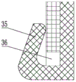
FIG. 3 is an enlarged schematic view at A in FIG. 2;
FIG. 4 is a schematic view of another angle configuration of a bed sand supporting apparatus according to an embodiment of the present invention;
FIG. 5 is an enlarged schematic view at B in FIG. 4;
FIG. 6 is a schematic view of the positioning hook installed in cooperation with the positioning slot;
FIG. 7 is a schematic view of the positioning hook mounted in cooperation with the positioning slot;
FIG. 8 is a schematic structural diagram of an internal circulation system according to an embodiment of the present invention;
FIG. 9 is a layout view of the bottom oxygenation pipe and the water outlet branch pipe according to the embodiment of the invention;
FIG. 10 is a schematic view of a water current lift according to an embodiment of the present invention;
FIG. 11 is a schematic diagram of a bottom aerator and a top aerator in accordance with embodiments of the present invention;
FIG. 12 is a schematic view of an external circulation system according to an embodiment of the present invention;
FIG. 13 is a top view of an external circulation system in accordance with an embodiment of the present invention;
in the figure: 1-a culture pond body; 2-filtering the tank body; 3-bottom sand supporting device; 31-a carrying surface; 32-water permeable holes; 33-supporting legs; 34-a carrier wall; 35-a positioning hook; 36-a positioning groove; 4-covering a sand layer; 51-a water outlet branch pipe; 52-water inlet hole; 53-water outlet header pipe; 54-water extraction and air outlet equipment; 55-an air outlet branch pipe; 56-air stone; 61-bottom oxygenation tube; 62-bottom oxygenation holes; 63-oxygenation header pipe; 71-top oxygen increasing main pipe; 72-top oxygen increasing branch pipe; 73-oxygen increasing air stone; 81-main sewage discharge pipe; 82-a blowdown upper branch pipe; 83-a sewage discharge lower branch pipe; 84-a waste valve; 85-a water return pipe; 86-a water return pump; 91-a filter bag; 92-brush holder body; 93-filter brushes; 94-ultraviolet lamp tube; 95-lamp tube support; 10-breeding sand bed.
Detailed Description
The invention is further illustrated below with reference to the figures and examples. In the following detailed description, certain exemplary embodiments of the present invention are described by way of illustration only. Needless to say, a person skilled in the art realizes that the described embodiments can be modified in various different ways without departing from the spirit and scope of the present invention. Accordingly, the drawings and description are illustrative in nature and not intended to limit the scope of the claims.
As shown in fig. 1, the high-yield circulating culture system for penaeus japonicus comprises a culture tank body 1 and a filtration tank body 2, in this embodiment, one culture tank body 1 corresponds to one filtration tank body 2, the culture tank body 1 and the filtration tank body 2 are both arranged indoors, a water replenishing device is arranged at the top of the culture tank body 1, the water replenishing device is used for replenishing water into the culture tank body 1, and the water replenishing device is the prior art, is well known to those skilled in the art, and is not described herein again; a bottom sand supporting device 3 is installed at the bottom of the culture pond body 1, a sand shielding layer 4 which can permeate water but cannot permeate sand is laid at the top of the bottom sand supporting device 3, water permeable cloth is adopted as the sand shielding layer 4, the water permeable cloth belongs to the prior art, a culture sand layer 10 for culturing sac prawns is laid on the surface of the sand shielding layer 4, and an internal circulating system for guiding culture water below the bottom sand supporting device 3 to the upper part of the culture sand layer 10 is installed in the culture pond body 1; a filtering device is installed in the filtering tank body 2, and an external circulating system for exchanging the culture water in the culture tank body 1 with the culture water filtered by the filtering device in the filtering tank body 2 is connected between the culture tank body 1 and the filtering tank body 2. When the sacked prawns are cultured, the internal circulating system moves all the time and is used for providing a good living water environment for the culture pond body 1; when the feeding is carried out for a half hour at the defecation peak, the external circulating system is opened, the operation is carried out for 0.5 to 1 hour to filter the culture water in the culture pond body 1, and through the combination of the internal circulating system and the external circulating system, a better growth environment is provided for the culture of the bursa prawns, the diseases of the culture of the bursa prawns are reduced, the survival rate and the yield of the bursa prawns are improved, meanwhile, the industrial culture of the bursa prawns is realized, and the effects of energy conservation and emission reduction are achieved; the system has the advantages of low investment, simple operation, time and labor saving and high use value for farmers.
Referring to fig. 2 to 7, the bottom sand supporting device 3 includes a tray body, the tray body includes a supporting surface 31, the surface of the supporting surface 31 is provided with a plurality of water permeable holes 32, the middle of the bottom end of the supporting surface 31 is evenly provided with a plurality of supporting legs 33, a supporting wall 34 is arranged around the bottom end of the supporting surface 31, and the bottom end of the supporting wall 34 is further provided with an inserting positioning device. During the design, the bottom of supporting leg 33 with the bottom of bearing wall 34 is on same horizontal plane, guarantees like this with when the bottom of a pool supporting device 3 was placed to, the whole support was comparatively stable. During the use, place the bottom of the pool with the tray, and adopt grafting positioner splices a plurality of trays and stably splices, then is in the one deck can permeate water but can not permeate husky sand covering 4 is laid on the bearing surface 31 surface, then is laying the one deck and be used for breeding the breed sand bed 10 of bag shrimp on sand covering 4 surface. Because the bearing surface 31 is provided with the permeable holes 32, the culture water above the pond can pass through the sand layer, the sand covering layer 4 and the permeable holes 32 to enter the pond bottom and deposit on the pond bottom, and because a gap is formed between the bearing surface 31 and the pond bottom, the gap forms a sewage discharge gap. Through adopting grafting positioner splices a plurality of trays, can guarantee the connection stability between the tray, prevents to produce the clearance between the tray and makes the sand leak down. The bottom sand supporting device 3 has the advantages of simple structure, reasonable design and the like, can meet the culture requirements of the penaeus monodon, and meanwhile, due to the arrangement of the inserting and positioning device, the connecting difficulty between the trays can be reduced, so that the bottom sand supporting device has the advantages of convenience in installation, accuracy in positioning, convenience in inserting and the like.
Referring to fig. 3 and 5, the inserting positioning device includes a positioning hook 35 and a positioning groove 36 that are matched with each other, the positioning hook 35 and the positioning groove 36 are disposed on the bearing wall 34 on opposite sides, the positioning hook 35 is disposed at a bottom end outside the bearing wall 34 and is bent outward, and the positioning groove 36 is disposed at a bottom end of the bearing wall 34; the positioning hooks 35 extend from the bottom end of the bearing wall 34 to the outside and extend to the inside and the top. Installation schematic diagram referring to fig. 6 and 7, during installation, the positioning slot 36 is inserted into the positioning hook 35 of another tray, so that the bottom end of the positioning hook 35 extends into the positioning slot 36, and then the top end of the positioning hook 35 is bent inwards, so that the top end of the positioning hook 35 presses against the bearing wall 34 of another tray, so that the bearing wall 34 between the two trays is contacted, and on one hand, the sand leakage phenomenon caused by a gap between the two trays is prevented; on the other hand, the connection between the two is prevented from being unstable due to the gap; when the tray is disassembled, the tray is lifted upwards. The positioning hook 35 has elasticity, so that the installation and the disassembly are more convenient, and after the installation, the top end of the positioning hook 35 can be pressed on the bearing wall 34 of another tray.
The surface of supporting leg 33 still be provided with bear the supporting leg strengthening rib that the strengthening rib is connected, the effect of supporting leg strengthening rib with bear the effect of strengthening rib and compare, the effect of supporting leg strengthening rib is the intensity that improves supporting leg 33 for realize the stable stay. The bearing wall 34 is provided with a plurality of sewage discharging holes, and the sewage discharging holes of the plurality of trays form a sewage discharging channel, so that waste between the bearing surface 31 and the bottom of the pool can be discharged through the sewage discharging channel formed by the sewage discharging holes. The water permeable holes 32 and the sewage draining holes are used as lightening holes for reducing the overall mass of the tray and facilitating transportation.
Referring to fig. 8 to 11, the internal circulation system includes a plurality of water outlet branch pipes 51 laid at the bottom of the culture pond body 1, a plurality of water inlet holes 52 are respectively and uniformly distributed on each water outlet branch pipe 51, a water outlet main pipe 53 communicated with each water outlet branch pipe 51 is arranged at one side of the pond wall of the culture pond body 1, a top water outlet of the water outlet main pipe 53 extends to the upper part of the culture water, and an air flow backflushing device for draining the culture water below the bottom sand supporting device 3 to the upper part of the culture sand layer 10 through the water inlet holes 52, the water outlet branch pipes 51 and the water outlet main pipe 53 in sequence is arranged on the pond wall of the culture pond body 1. The internal circulating system is used for guiding the culture water below the bottom sand supporting device 3 to the position above the culture sand layer 10, then the culture water moves downwards from the upper part and enters the bottom of the culture pond body 1 through the culture sand layer 10 and the bottom sand supporting device 3, so that the culture water in the culture pond body 1 has a circulating flow path, and the culture water in the culture pond body 1 is always moving live water; the internal circulation system has a simple structure and a reasonable design, can effectively reduce the rotten and smelly speed of pollutants, provides a good breath growth environment for the marsupenaeus japonicas, and has a good popularization value.
Referring to fig. 10, the air flow backflushing device includes a water lifting and air outlet device 54 installed on the wall of the culture pond body 1, the water lifting and air outlet device 54 is connected with a plurality of air outlet branch pipes 55 extending from the top water outlet to the inside of the water outlet main pipe 53, and the bottom ends of the air outlet branch pipes 55 extend below the surface of the culture water and are connected with air stones 56. The water lifting and air outlet device 54 is an oxygen generator, the water lifting and air outlet device 54, the air outlet branch pipe 55 and the air outlet stone 56 are oxygen generation devices in the prior art, and the water lifting function is realized by the oxygen generation devices.
Referring to fig. 9, all the water outlet branch pipes 51 are uniformly distributed and installed at the bottom of the culture tank body 1 in parallel, and each water outlet branch pipe 51 extends from one side of the tank wall of the culture tank body 1 to the other side of the tank wall, so as to ensure that water at each position of the bottom of the culture tank body 1 can be discharged through the water outlet branch pipe 51, so that water at each position in the culture tank body 1 can be movable running water, and no dead angle is formed.
Working principle diagram of internal circulation system:
because the water inlet 52, the water outlet branch pipes 51 and the water outlet main pipe 53 are communicated, the culture water in the culture pond body 1 can enter the water outlet main pipe 53 through the water inlet 52 and the water outlet branch pipes 51, and according to the principle of a communicating vessel, the liquid level height of the culture water in the water outlet main pipe 53 is consistent with the liquid level height of the culture water in the culture pond body 1;
when the water lifting and air outlet device 54 works, a large number of bubbles are generated and discharged into the water outlet main pipe 53 through the air outlet branch pipe 55 and the air outlet stone 56, and the air outlet stone 56 is located below the liquid level of the culture water, so the bubbles continuously impact the culture water in the water outlet main pipe 53, and occupy a part of the volume in the water outlet main pipe 53 due to the generation of the bubbles, so that the liquid level of the culture water in the water outlet main pipe 53 is increased, and the bubbles continuously flow out and are faster in speed, so that the pressure of the culture water in the water outlet main pipe 53 is lower according to bernoulli's principle, and as the bubbles continuously generate, the liquid level in the water outlet main pipe 53 is continuously increased and exceeds the top end of the water outlet main pipe 53, and then the culture water is discharged from the top water outlet port of the water main pipe 53, and in order to keep the pressure balance after the culture water is discharged, the aquaculture water at the bottom of the aquaculture pond body 1 enters the main water outlet pipe 53 through the water inlet holes 52 and the water outlet branch pipes 51, and is continuously supplemented with water into the main water outlet pipe 53, so that the aquaculture water in the main water outlet pipe 53 is continuously discharged outwards and flows into the upper part of the aquaculture sand layer 10, and the process of lifting the aquaculture water from bottom to top is completed;
after the culture water is discharged to the upper part of the culture pond body 1, the culture water moves from top to bottom, enters the bottom of the culture pond body 1 through the culture sand layer 10 and the bottom sand supporting device 3, and is finally discharged through the water inlet hole 52, the water outlet branch pipe 51 and the water outlet main pipe 53, so that the culture water in the culture pond body 1 has a circulating flow path, and the culture water continuously circulates in the culture pond body 1, and the culture water in the culture pond body 1 is always moving live water as seen in the arrow flow direction in fig. 10; when the culture water moves upwards and is discharged from the water outlet main pipe 53, the culture water is mixed with bubbles and then moves together with the bubbles and is discharged into the culture tank body 1, so that the internal circulation of the culture water is completed, and meanwhile, oxygen is added into the culture tank body 1;
the internal circulation system only utilizes the water lifting and air outlet equipment 54 with the oxygen generation function, and combines the communicating vessel principle and the Bernoulli principle to realize the internal circulation flow of the aquaculture water, so as to replace a water pump in the prior art, and an oxygen generation device is an essential device for the existing marsupenaeus japonicus aquaculture.
Referring to fig. 9 and 11, a bottom oxygen increasing device located below the bottom sand supporting device 3 is installed at the bottom of the culture pond body 1, and a top oxygen increasing device with a bottom end extending into the culture water above the culture sand layer 10 is installed above the culture pond body 1. The bottom oxygenation device is in breed the bottom of cell body 1 produces oxygen, and oxygen upward movement passes in proper order bottom sand supporting device 3 with breed sand bed 10, oxygen from the bottom up motion in-process, for breed cell body 1 wholly provides oxygen for the oxygen of each position all satisfies in the breed water. The culture pond body 1 is arranged indoors, and the top oxygenation device is arranged on the top of an indoor shed through a support.
Referring to fig. 9 and 11, the bottom oxygen increasing device includes a plurality of bottom oxygen increasing pipes 61 laid at the bottom of the culture pond body 1, a plurality of bottom oxygen increasing holes 62 are uniformly distributed on each bottom oxygen increasing pipe 61, an oxygen increasing main pipe 63 communicated with each bottom oxygen increasing pipe 61 is further installed in the culture pond body 1, one end of the oxygen increasing main pipe 63 extends to the upper side of culture water, and a bottom oxygen generating device for charging oxygen into the oxygen increasing main pipe 63 is connected to the oxygen increasing main pipe 63. When the bottom oxygen generating equipment works, a large amount of oxygen is generated, enters the bottom oxygen increasing pipe 61 through the oxygen increasing main pipe 63 and is then discharged through the bottom oxygen increasing holes 62, so that oxygen is provided for the culture water below the culture sand layer 10, and the flow direction of the hollow arrow in fig. 11 is shown. The oxygen located under the cultivation sand 10 moves upward, passes through the cultivation sand 10 and then disappears from the top of the cultivation water. The bottom oxygenation device is in breed the bottom of cell body 1 produces oxygen, and oxygen upward movement passes in proper order bottom sand supporting device 3 with breed sand bed 10, oxygen from the bottom up motion in-process, for breed cell body 1 wholly provides oxygen for the oxygen of each position all satisfies in the breed water. The bottom oxygen plant is not shown in fig. 11.
Referring to fig. 9, all the bottom oxygenation pipes 61 are uniformly distributed and installed at the bottom of the culture pond body 1 in parallel, and each bottom oxygenation pipe 61 extends from one side of the pond wall of the culture pond body 1 to the other side of the pond wall to ensure that oxygen can be discharged from each position of the bottom of the culture pond body 1, so that the oxygen content at each position of the bottom of the culture pond body 1 is sufficient, and a local oxygen deficiency phenomenon cannot occur.
The top oxygenation device comprises a top oxygenation main pipe 71 fixedly installed above the culture pond body 1 through a support, a top oxygenation branch pipe 72 which vertically falls downwards and extends below the surface of culture water is connected to the top oxygenation main pipe 71, and an oxygenation air stone 73 is installed at the bottom end of the top oxygenation branch pipe 72; one end of the top oxygen-increasing main pipe 71 is connected with a top oxygen-generating device for filling oxygen into the top oxygen-increasing main pipe 71. When the top oxygen generating equipment works, a large amount of oxygen is generated, enters the top oxygen increasing branch pipe 72 through the top oxygen increasing main pipe 71 and is then discharged through the oxygen increasing air stone 73, and the oxygen is provided for the culture water on the upper part of the culture sand layer 10.
The top oxygen generating equipment, the bottom oxygen generating equipment and the water and gas lifting and discharging equipment 54 are all oxygen generators, are well known to persons skilled in the art, and are not described herein again. In this embodiment, three oxygen generators are used for respective operation, and certainly, one oxygen generator may be used to be connected to the water flow lifting device, the bottom oxygen increasing device and the top oxygen increasing device through pipelines respectively, so as to provide oxygen integrally.
The invention has three oxygenation modes:
firstly, when the water flow lifting device works, a part of oxygen can be generated at the top of the culture pond body 1, see ③ in the picture 11, secondly, when the top oxygen increasing device works, a part of oxygen can be generated at the top or the upper part of the culture pond body 1, see ② in the picture 11, thirdly, when the bottom oxygen increasing device works, a part of oxygen can be generated at the bottom of the culture pond body 1, see ① in the picture 11, oxygen generation and oxygen increasing are combined through the three modes, the oxygen content can be effectively improved, and compared with a single oxygen generation mode or a top oxygen generation mode in the prior art, the combined oxygen generation mode can ensure that the top and the bottom of the culture sand layer 10 have more oxygen content, and the oxygen at each position in the culture pond body 1 is satisfied.
Referring to fig. 12 and 13, the external circulation system includes a main sewage drainage pipe 81 disposed inside the culture tank body 1, the main sewage discharge pipe 81 is provided with an upper sewage discharge branch pipe 82 positioned at the top of the culture sand layer 10 and a lower sewage discharge branch pipe 83 positioned at the bottom of the culture pond body 1, the tail end of the main sewage discharge pipe 81 extends into the filtering tank body 2 and is connected with the filtering device, a blowdown valve 84 is correspondingly installed at the tail end of the blowdown main pipe 81, the blowdown valve 84 is an electromagnetic valve, a return pipe 85 which discharges the filtered culture water in the filter tank body 2 to the culture sand layer 10 in the culture tank body 1 is also arranged in the filter tank body 2, a water return pump 86 is correspondingly installed on the water return pipe 85, the sewage main pipe 81 is located on the front side of the filtering device, and the water return pipe 85 is located on the rear side of the filtering device.
Filter equipment is including connecting the filtration bag 91 of the tail end of blowdown main pipe 81, filter bag 91 and be located filter the cell body 2, lie in on the filter cell body 2 the blowdown main pipe 81 with arranged multirow brush device and ultraviolet germicidal device between the filter equipment, the brush device is including fixing brush support body 92 on the filter cell body 2, it is in to have arranged a plurality of immersions on brush support body 92 filter the filtration brush 93 in the filtration water of filter cell body 2. The filter bag 91 is known in the art and known to those skilled in the art, and will not be described in detail herein. The ultraviolet sterilization device comprises a plurality of ultraviolet lamp tubes 94, the ultraviolet lamp tubes 94 are fixed in the filtering tank body 2 through lamp tube supports 95, can be located below the brush device and can be alternately arranged with the brush device at intervals, so long as the ultraviolet lamp tubes 94 are immersed in the filtered water of the filtering tank body 2, and are used for sterilization and disinfection after filtration, thereby further improving the filtration effect, wherein the ultraviolet lamp tubes 94 are the prior art, are well known by persons skilled in the art and are not described herein again.
During design, the liquid level in the filtering tank body 2 is always lower than the liquid level in the culture tank body 1, so that when sewage needs to be discharged, the sewage discharge valve 84 is controlled to be opened, the communicating vessel principle is facilitated, and culture water with high liquid level can enter low liquid level for liquid level balance; when the filtering tank body 2 is designed, the breeding tank body 1 is arranged at one side of the main water outlet pipe 53 in the internal circulation system, so that when the main water outlet pipe 53 in the internal circulation system drains water upwards, water flows to one side away from the main water outlet pipe 53 according to the flowing route of the water, referring to the moving direction in fig. 10, when the water flows to one side away from the main water outlet pipe 53, the pollutants above the breeding sand layer 10 flow to one side away from the main water outlet pipe 53 and are gathered at one side away from the main water outlet pipe 53, so that when the filtering tank body 2 is arranged at one side away from the main water outlet pipe 53, more pollutants in the breeding tank body 1 enter the filtering tank body 2 through the upper sewage discharge branch pipe 82, and the discharge efficiency of the pollutants can be improved.
The working principle of the external circulation system is as follows:
after the blowdown valve 84 is opened, the blowdown lower branch pipe 83 and the blowdown upper branch pipe 82 are communicated, so that culture water below the bottom sand supporting device 3 carries pollutants, enters the blowdown main pipe 81 through the blowdown lower branch pipe 83, is discharged into the filtering tank body 2, and is subjected to blowdown treatment below the culture sand layer 10; the culture water above the culture sand layer 10 enters the main sewage discharge pipe 81 through the upper sewage discharge branch pipe 82 and is discharged into the filtering tank body 2, and sewage discharge treatment is performed on the upper part of the culture sand layer 10; after the aquaculture water enters the filtering tank body 2 through the main sewage discharge pipe 81, the aquaculture water firstly enters the filtering bag 91 and then enters the filtering tank body 2 through the bag wall of the filtering bag 91, and when the aquaculture water passes through the filtering bag 91, the aquaculture water is filtered for one time;
since the breeding water in the breeding tank 1 enters the filtering tank 2 and then the backwater pump 86 is simultaneously turned on to ensure that the breeding water in the breeding tank 1 cannot be reduced to affect the growth of the shrimps, when the blowdown valve 84 is turned on, the backwater pump 86 is turned on, and when the backwater pump 86 is turned on, the water in the filtering tank 2 is discharged back into the breeding tank 1 through the backwater pipe 85, because the backwater pipe 85 and the blowdown main pipe 81 are located at the front and rear ends of the filtering tank 2, when the backwater pipe 85 discharges water outwards and the blowdown main pipe 81 enters water inwards, the water in the filtering tank 2 has a moving path flowing from the blowdown main pipe 81 side to the backwater pipe 85 side, referring to fig. 13, after the breeding water is once filtered and enters the filtering tank 2, the water moves along a path flowing from the blowdown main pipe 81 side to the backwater pipe 85 side, in the moving process, the culture water passes through the multiple rows of the brush devices and the ultraviolet sterilization devices, is filtered again by the filtering brushes 93, is sterilized by the ultraviolet lamp tubes 94, moves to one side of the water return pipe 85 after being filtered and sterilized again, is discharged into the culture pond body 1 through the water return pipe 85, and forms a filtering circulation path between the culture pond body 1 and the filtering pond body 2 through the main sewage discharge pipe 81 and the water return pipe 85, wherein the circulation path is defined as an external circulation system of the culture pond body 1; the external circulation system realizes drainage and water exchange, washes the sand and the sand, directly reduces the residual baits and the residual excrement on the sand and the sand, and can effectively avoid the residual baits and the excrement from gathering the sand layer by combining with the bottom sand bearing device 3, prevent the sand layer from blackening caused by the gathering of a large amount of pollutants, and provide a good growing environment for the production of the penaeus japonicus.
The foregoing shows and describes the general principles, essential features, and advantages of the invention. It will be understood by those skilled in the art that the present invention is not limited to the embodiments described above, which are described in the specification and illustrated only to illustrate the principle of the present invention, but that various changes and modifications may be made therein without departing from the spirit and scope of the present invention, which fall within the scope of the invention as claimed. The scope of the invention is defined by the appended claims and equivalents thereof.
Claims (10)
1. The high-yield circulating culture system for the penaeus japonicus comprises a culture pond body and a filtering pond body, and is characterized in that: a bottom sand supporting device is installed at the bottom of the culture pond body, a culture sand layer is laid at the top of the bottom sand supporting device, and an internal circulating system which leads culture water below the bottom sand supporting device to be above the culture sand layer is installed in the culture pond body; the filter tank body is internally provided with a filter device, and an external circulating system for exchanging the culture water in the culture tank body with the culture water filtered by the filter device in the filter tank body is connected between the culture tank body and the filter tank body.
2. The high-yield circulating aquaculture system for penaeus japonicus as claimed in claim 1, characterized in that: the sediment supporting device comprises a tray body, the tray body comprises a bearing surface, a plurality of water permeable holes are formed in the surface of the bearing surface, a plurality of supporting legs are evenly distributed in the middle of the bottom end of the bearing surface, a bearing wall is arranged on the periphery of the bottom end of the bearing surface, and an inserting positioning device is further arranged at the bottom end of the bearing wall.
3. The high-yield circulating aquaculture system for penaeus japonicus as claimed in claim 2, characterized in that: the inserting positioning device comprises a positioning hook and a positioning groove which are matched with each other, the positioning hook and the positioning groove are arranged on the bearing walls on two opposite sides, the positioning hook is arranged at the bottom end outside the bearing walls and is bent outwards, and the positioning groove is arranged at the bottom end of the bearing walls; the positioning hook extends outwards and straightly from the bottom end of the bearing wall and then extends upwards and inwards in a bending way.
4. The high-yield circulating aquaculture system for penaeus japonicus as claimed in claim 1, characterized in that: the internal circulation system comprises a plurality of water outlet branch pipes laid at the bottom of the culture pond body, a plurality of water inlet holes are uniformly distributed on each water outlet branch pipe, a water outlet main pipe communicated with each water outlet branch pipe is arranged on one side of the pond wall of the culture pond body, a top water outlet of the water outlet main pipe extends to the upper part of culture water, and an air flow backflushing device used for leading the culture water below the bottom sand supporting device to flow to the upper part of the culture sand layer through the water inlet holes, the water outlet branch pipes and the water outlet main pipe is arranged on the pond wall of the culture pond body.
5. The high-yield circulating aquaculture system for penaeus japonicus as claimed in claim 4, characterized in that: the airflow backflushing device comprises a water lifting and air outlet device installed on the wall of the culture pond body, the water lifting and air outlet device is connected with a plurality of air outlet branch pipes, the top water outlets of the air outlet branch pipes stretch into the inside of the water outlet main pipe, and the bottom ends of the air outlet branch pipes stretch into the position below the surface of culture water and are connected with air stones.
6. The high-yield circulating aquaculture system for penaeus japonicus as claimed in claim 1, characterized in that: the bottom oxygenation device is arranged at the bottom of the culture pond body and below the bottom sand bearing device, and the top oxygenation device is arranged above the culture pond body and extends to the bottom of the culture pond body and is arranged in the culture water above the culture sand layer.
7. The high-yield circulating aquaculture system for penaeus japonicus as claimed in claim 6, characterized in that: the bottom oxygenation device comprises a plurality of bottom oxygenation pipes paved at the bottom of the culture pond body, a plurality of bottom oxygenation holes are uniformly distributed on each bottom oxygenation pipe, an oxygenation header pipe communicated with each bottom oxygenation pipe is further installed in the culture pond body, one end of each oxygenation header pipe extends to the upper part of culture water, and a bottom oxygen generation device for filling oxygen into the oxygenation header pipe is connected to one end of each oxygenation header pipe.
8. The high-yield circulating aquaculture system for penaeus japonicus as claimed in claim 6, characterized in that: the top oxygenation device comprises a top oxygenation main pipe fixedly installed above the culture pond body through a support, the top oxygenation main pipe is connected with a top oxygenation branch pipe which is vertically dropped downwards and extends below the surface of culture water, and the bottom end of the top oxygenation branch pipe is provided with an oxygen increasing stone; one end of the top oxygen increasing main pipe is connected with a top oxygen generating device which fills oxygen into the top oxygen increasing main pipe.
9. The high-yield circulating aquaculture system for penaeus japonicus as claimed in claim 1, characterized in that: outside circulation system is in including setting up breed the inside blowdown of cell body is responsible for, the blowdown is responsible for and is provided with and is located breed the blowdown upper branch pipe at sand bed top and is located breed the blowdown lower branch pipe of cell body bottom, the tail end that the blowdown was responsible for extends to in the filtering ponds with filter equipment connects, the tail end correspondence that the blowdown was responsible for is installed the blowdown valve, still be provided with in the filtering ponds with breed water after the filtration in the filtering ponds is discharged extremely breed in the cell body breed the wet return of sand bed top, correspond on the wet return and install the wet return pump, the blowdown is responsible for and is located filter equipment's front side, the wet return is located filter equipment's rear side.
10. The high-yield circulating aquaculture system for marsupenaeus japonicus as claimed in claim 9, wherein: filter equipment is including connecting the filtration bag of the tail end that the blowdown was responsible for, filter the bag and be located in the filtering ponds, it is located on the filtering ponds body the blowdown is responsible for with arranged multirow brush device and ultraviolet germicidal device between the filter equipment, the brush device is including fixing brush support body on the filtering ponds body, it is in to have arranged a plurality of infusions on the brush support body filtering brushes in the filtration water of filtering ponds body, ultraviolet germicidal device contains many ultraviolet tube.
Priority Applications (1)
| Application Number | Priority Date | Filing Date | Title |
|---|---|---|---|
| CN201911371948.7A CN111084145A (en) | 2019-12-27 | 2019-12-27 | High-yield circulating culture system for marsupenaeus japonicus |
Applications Claiming Priority (1)
| Application Number | Priority Date | Filing Date | Title |
|---|---|---|---|
| CN201911371948.7A CN111084145A (en) | 2019-12-27 | 2019-12-27 | High-yield circulating culture system for marsupenaeus japonicus |
Publications (1)
| Publication Number | Publication Date |
|---|---|
| CN111084145A true CN111084145A (en) | 2020-05-01 |
Family
ID=70397391
Family Applications (1)
| Application Number | Title | Priority Date | Filing Date |
|---|---|---|---|
| CN201911371948.7A Pending CN111084145A (en) | 2019-12-27 | 2019-12-27 | High-yield circulating culture system for marsupenaeus japonicus |
Country Status (1)
| Country | Link |
|---|---|
| CN (1) | CN111084145A (en) |
Cited By (1)
| Publication number | Priority date | Publication date | Assignee | Title |
|---|---|---|---|---|
| CN116349628A (en) * | 2023-03-16 | 2023-06-30 | 江苏海洋大学 | Substrate device for culturing Penaeus japonicus and culturing method |
-
2019
- 2019-12-27 CN CN201911371948.7A patent/CN111084145A/en active Pending
Cited By (1)
| Publication number | Priority date | Publication date | Assignee | Title |
|---|---|---|---|---|
| CN116349628A (en) * | 2023-03-16 | 2023-06-30 | 江苏海洋大学 | Substrate device for culturing Penaeus japonicus and culturing method |
Similar Documents
| Publication | Publication Date | Title |
|---|---|---|
| CN204707768U (en) | Cycle water fish seedling fostering system | |
| CN106719270B (en) | A kind of aquaculture life-support system and its application method | |
| CN207135987U (en) | A kind of gas stripping type circulating water culture system | |
| CN203136806U (en) | Combined modular recirculating aquaculture system | |
| CN206433595U (en) | A kind of aquaculture pond | |
| CN108323469A (en) | Pisces pool recirculated water ecological fish cultivating system | |
| CN105918171A (en) | Indoor factory culture method and device for penaeus vannamei | |
| CN109122529A (en) | A kind of half batch production pond inner-circulative culture system | |
| CN107711684A (en) | Multifunctional aquatic product cultivates the water purification circulatory system | |
| CN104996344B (en) | Abalone fry culture method | |
| CN203505333U (en) | Device for breeding fishes and shrimps in stepped manner by using river water with different qualities | |
| CN111084145A (en) | High-yield circulating culture system for marsupenaeus japonicus | |
| CN211581227U (en) | High-yield circulating culture system for marsupenaeus japonicus | |
| CN209105967U (en) | A kind of half batch production pond inner-circulative culture system | |
| CN205695043U (en) | A kind of flowing water high yielding culture system | |
| CN105981667B (en) | A kind of industrial circulating water high density stereo ecological cultivating system | |
| CN205756606U (en) | Eriocheir sinensis industrialized culture water processes and temperature-controlling system | |
| CN211881761U (en) | Convenient-to-plug-in type marsupenaeus japonicus high-yield culture pond bottom sand tray | |
| CN204634758U (en) | A kind of fresh water seed semi-aerobic landfill system | |
| CN103548727B (en) | Culture method of device for cascaded culture of fishes and shrimps by separately using river water according to quality | |
| CN210017498U (en) | Three-dimensional circulation comprehensive planting and breeding device | |
| CN209677116U (en) | A kind of high position shrimp canopy | |
| CN211672001U (en) | Water internal circulation system of high-yield culture pond for marsupenaeus japonicus | |
| CN208300723U (en) | A kind of industrial circulating water fry rearing system | |
| CN110178784A (en) | A kind of C. guichenoti circulating water culture system |
Legal Events
| Date | Code | Title | Description |
|---|---|---|---|
| PB01 | Publication | ||
| PB01 | Publication | ||
| SE01 | Entry into force of request for substantive examination | ||
| SE01 | Entry into force of request for substantive examination |