CN111050849B - Method for persistence management of PET detectors - Google Patents
Method for persistence management of PET detectors Download PDFInfo
- Publication number
- CN111050849B CN111050849B CN201880057036.XA CN201880057036A CN111050849B CN 111050849 B CN111050849 B CN 111050849B CN 201880057036 A CN201880057036 A CN 201880057036A CN 111050849 B CN111050849 B CN 111050849B
- Authority
- CN
- China
- Prior art keywords
- radiation
- pet
- threshold
- gain factor
- pet detector
- Prior art date
- Legal status (The legal status is an assumption and is not a legal conclusion. Google has not performed a legal analysis and makes no representation as to the accuracy of the status listed.)
- Active
Links
Images


Classifications
-
- G—PHYSICS
- G01—MEASURING; TESTING
- G01T—MEASUREMENT OF NUCLEAR OR X-RADIATION
- G01T1/00—Measuring X-radiation, gamma radiation, corpuscular radiation, or cosmic radiation
- G01T1/29—Measurement performed on radiation beams, e.g. position or section of the beam; Measurement of spatial distribution of radiation
- G01T1/2914—Measurement of spatial distribution of radiation
- G01T1/2985—In depth localisation, e.g. using positron emitters; Tomographic imaging (longitudinal and transverse section imaging; apparatus for radiation diagnosis sequentially in different planes, steroscopic radiation diagnosis)
-
- A—HUMAN NECESSITIES
- A61—MEDICAL OR VETERINARY SCIENCE; HYGIENE
- A61N—ELECTROTHERAPY; MAGNETOTHERAPY; RADIATION THERAPY; ULTRASOUND THERAPY
- A61N5/00—Radiation therapy
- A61N5/10—X-ray therapy; Gamma-ray therapy; Particle-irradiation therapy
- A61N5/1042—X-ray therapy; Gamma-ray therapy; Particle-irradiation therapy with spatial modulation of the radiation beam within the treatment head
- A61N5/1045—X-ray therapy; Gamma-ray therapy; Particle-irradiation therapy with spatial modulation of the radiation beam within the treatment head using a multi-leaf collimator, e.g. for intensity modulated radiation therapy or IMRT
-
- A—HUMAN NECESSITIES
- A61—MEDICAL OR VETERINARY SCIENCE; HYGIENE
- A61N—ELECTROTHERAPY; MAGNETOTHERAPY; RADIATION THERAPY; ULTRASOUND THERAPY
- A61N5/00—Radiation therapy
- A61N5/10—X-ray therapy; Gamma-ray therapy; Particle-irradiation therapy
- A61N5/1077—Beam delivery systems
-
- G—PHYSICS
- G01—MEASURING; TESTING
- G01T—MEASUREMENT OF NUCLEAR OR X-RADIATION
- G01T1/00—Measuring X-radiation, gamma radiation, corpuscular radiation, or cosmic radiation
- G01T1/16—Measuring radiation intensity
- G01T1/17—Circuit arrangements not adapted to a particular type of detector
- G01T1/172—Circuit arrangements not adapted to a particular type of detector with coincidence circuit arrangements
-
- G—PHYSICS
- G01—MEASURING; TESTING
- G01T—MEASUREMENT OF NUCLEAR OR X-RADIATION
- G01T1/00—Measuring X-radiation, gamma radiation, corpuscular radiation, or cosmic radiation
- G01T1/16—Measuring radiation intensity
- G01T1/20—Measuring radiation intensity with scintillation detectors
- G01T1/202—Measuring radiation intensity with scintillation detectors the detector being a crystal
- G01T1/2023—Selection of materials
-
- G—PHYSICS
- G01—MEASURING; TESTING
- G01T—MEASUREMENT OF NUCLEAR OR X-RADIATION
- G01T1/00—Measuring X-radiation, gamma radiation, corpuscular radiation, or cosmic radiation
- G01T1/16—Measuring radiation intensity
- G01T1/20—Measuring radiation intensity with scintillation detectors
- G01T1/208—Circuits specially adapted for scintillation detectors, e.g. for the photo-multiplier section
-
- G—PHYSICS
- G01—MEASURING; TESTING
- G01T—MEASUREMENT OF NUCLEAR OR X-RADIATION
- G01T7/00—Details of radiation-measuring instruments
- G01T7/005—Details of radiation-measuring instruments calibration techniques
-
- A—HUMAN NECESSITIES
- A61—MEDICAL OR VETERINARY SCIENCE; HYGIENE
- A61N—ELECTROTHERAPY; MAGNETOTHERAPY; RADIATION THERAPY; ULTRASOUND THERAPY
- A61N5/00—Radiation therapy
- A61N5/10—X-ray therapy; Gamma-ray therapy; Particle-irradiation therapy
- A61N5/1048—Monitoring, verifying, controlling systems and methods
- A61N5/1049—Monitoring, verifying, controlling systems and methods for verifying the position of the patient with respect to the radiation beam
- A61N2005/1052—Monitoring, verifying, controlling systems and methods for verifying the position of the patient with respect to the radiation beam using positron emission tomography [PET] single photon emission computer tomography [SPECT] imaging
-
- A—HUMAN NECESSITIES
- A61—MEDICAL OR VETERINARY SCIENCE; HYGIENE
- A61N—ELECTROTHERAPY; MAGNETOTHERAPY; RADIATION THERAPY; ULTRASOUND THERAPY
- A61N5/00—Radiation therapy
- A61N5/10—X-ray therapy; Gamma-ray therapy; Particle-irradiation therapy
- A61N2005/1092—Details
Abstract
Methods and apparatus for acquiring positron emission (or PET) data in the presence of ionizing radiation that causes afterglow of a PET detector are disclosed herein. In one variation, the method includes adjusting a coincidence trigger threshold of the PET detector during the treatment session. In one variation, the method includes adjusting a gain factor used in positron emission data acquisition (e.g., a gain factor used to multiply and/or shift the output(s) of the PET detector (s)) during the treatment session. In some variations, a method for acquiring positron emission data during a radiation therapy session includes: after emission of the radiation pulse by the linac, communication between the PET detector and the signal processor of the controller is suspended for a predetermined period of time.
Description
Cross Reference to Related Applications
This application claims priority from U.S. provisional patent application No.62/531,260, filed 2017, month 7, day 11, the entire contents of which are incorporated herein by reference.
Technical Field
The present disclosure relates to methods for use in a radiation therapy system that includes a linear accelerator (or other ionizing radiation source) and one or more positron emission (or PET) detectors.
Background
Radiation therapy systems typically have a radiation source (e.g., a linear accelerator or a linear accelerator) that generates a therapeutic radiation beam for irradiating a targeted tissue region, such as a tumor region of a patient. Although the generated radiation beam may be directed toward the target region and may be beam-limited by one or more jaws and/or collimators, a portion of the radiation beam may be deflected and/or scattered from the target region. This scattered radiation may interfere with the function of other components of the radiation therapy system.
For example, scattered or stray radiation may affect the ability of various detectors (such as X-ray and/or PET detectors) in a radiation therapy system to accurately acquire data. The PET detectors in a radiation therapy system may be affected such that the response of the PET detectors to scattered or stray radiation may be indistinguishable from the true positron emission events. In the case of high levels of radiation (e.g., such as during a radiation pulse from a linac), the PET detector may "blank" and/or saturate. Which may render them unable to meaningfully detect positron emission data.
Accordingly, it may be desirable to develop methods and apparatus for managing the risk of equipment damage and/or data damage due to scattered radiation from a linear accelerator.
Disclosure of Invention
Methods and apparatus for acquiring positron emission (or PET) data in the presence of ionizing radiation that causes afterglow of a PET detector are disclosed herein. In one variation, the method may include adjusting a coincidence trigger threshold of the PET detector during the treatment session. The coincidence trigger threshold may increase as the persistence of the PET detector increases. For example, the coincidence trigger threshold may increase as the dark count rate of one or more PET detectors increases and/or exceeds a threshold dark count rate. Alternatively or additionally, the coincidence trigger threshold may increase as the bias current of the one or more PET detectors increases and/or exceeds a threshold bias current level. The coincidence trigger threshold may also be adjusted based on a measured temperature of the system (e.g., at or near the PET detector), where the coincidence trigger threshold may increase as the system temperature increases. In some variations, the coincidence trigger threshold may be adjusted based on the radiation output of the radiation source or the linac. For example, the coincidence trigger threshold may be adjusted when the number of emitted radiation pulses exceeds a predetermined threshold, and/or based on a pulse schedule, and/or based on an accumulated amount of radiation emitted by the linac during a treatment session. In some variations, the coincidence trigger threshold may be adjusted if the synchronization between two system components (e.g., the linac and the collimator) shifts and the timing shift exceeds a predetermined threshold.
In some variations, a method for acquiring positron emission data during a radiation therapy session may comprise: after the linac has emitted radiation pulses, communication between the PET detector and the signal processor of the controller is suspended for a predetermined period of time. For example, the predetermined period of time may be about 100 μ s or more, or about 200 μ s or more. Alternatively or additionally, the predetermined period of time may be determined at least in part by a width or duration of the linac radiation pulse. For example, the predetermined period of time may be about 25 times or about 100 times longer than the duration of the linac pulse. After the predetermined period of time has elapsed, communication between the PET detector and the signal processor may resume, and positron emission data may be transmitted from the detector to the signal processor and/or acquired by the signal processor for analysis and/or storage by the controller.
In other variations, the radiation therapy system can include a radiation source, a plurality of PET detectors (e.g., a PET detector array), and a radiation blocking shield that is movable over the plurality of PET detectors. The radiation blocking shield may be positioned over the PET detector during a radiation interval when the radiation source emits radiation, and may be positioned away from the PET detector during a detection interval when the radiation source does not emit radiation.
One variation of a radiation therapy system may include: a radiation source configured to direct one or more radiation pulses to a PET-avid region of interest, wherein each radiation pulse has a predetermined pulse duration; a plurality of PET detectors configured to detect a positron emission path by detecting positron annihilation photon pairs incident on a portion of the detectors within a coincidence time window and generating detector signals exceeding a coincidence trigger threshold; and a controller in communication with the plurality of PET detectors, wherein the controller is configured to adjust the coincidence trigger threshold during the treatment session. The controller may be configured to adjust the coincidence trigger threshold after a threshold number of radiation pulses have been directed to the region of interest. The threshold number of radiation pulses may be about 1000 radiation pulses. The coincidence trigger threshold can be from about two photon triggers to about five photon triggers. The coincidence trigger threshold may be a first coincidence trigger threshold and the threshold number of radiation pulses may be a first threshold number of radiation pulses, and the controller may be configured to adjust the first coincidence trigger threshold to a second coincidence trigger threshold after a second threshold number of radiation pulses have been directed to the region of interest. The second coincidence trigger threshold may be greater than the first coincidence trigger threshold, and the second threshold number of radiation pulses is greater than the first threshold number of radiation pulses. The second coincidence trigger threshold may be from about four photon triggers to about six photon triggers and the second threshold number of radiation pulses may be about 2000. The second coincidence trigger threshold may be less than the first coincidence trigger threshold, and the second threshold number of radiation pulses may be greater than the first threshold number of radiation pulses. The controller may be configured to adjust the coincidence trigger threshold based on a timing change greater than 10% from a baseline, and/or may be configured to adjust the coincidence trigger threshold when a dark count rate of one or more of the plurality of PET detectors exceeds a threshold dark count rate. The threshold dark count rate may be, for example, from about 3Mcps to about 10 Mcps. Optionally, the controller may further comprise a current detector configured to measure a bias current of one or more of the plurality of PET detectors, and wherein the controller is configured to adjust the coincidence trigger threshold when the bias current exceeds a threshold bias current value. The threshold bias current value may be from about 0.1mA to about 5mA, e.g., about 1mA, about 3 mA. Alternatively or additionally, the controller may be configured to adjust the coincidence trigger threshold when an amount of radiation emitted from the radiation source exceeds a threshold radiation level. The threshold radiation level can be from about 0.1cGy/min to about 1 cGy/min. The controller may further include a signal processor and a switch configured to selectively communicate the PET detector output signal to the signal processor. The switch may be configured to pause communication of the PET detector output signals to the signal processor for a predetermined period of time after each radiation pulse, wherein a ratio of the predetermined period of time to a duration of each radiation pulse may be between about 25: 1 to about 100: 1. The controller may be configured to suspend communication of the PET detector output signals to the signal processor for the duration of each radiation pulse and for a predetermined period of time after each radiation pulse. The controller may be configured to suspend communication of the PET detector output signal to the signal processor based on the gating signal. The gating signal may cause the controller to pause communication of the PET detector output signals to the signal processor for at least 100 μ s after each radiation pulse. In some variations, the gating signal may cause the controller to pause the communication of the PET detector output signals to the signal processor for at least 200 μ β after each radiation pulse. Alternatively or additionally, the controller may be configured to adjust the coincidence trigger threshold based at least in part on a timing schedule of the radiation pulses.
Also disclosed herein is a method for automatically adjusting a coincidence trigger threshold of a PET detector. The method can comprise the following steps: measuring a characteristic of a radiation therapy system including two or more PET detectors having coincident trigger thresholds; determining whether the measured characteristic exceeds a predetermined threshold for the characteristic; and adjusting the coincidence trigger threshold based on the determination of whether the measured characteristic exceeds the threshold for the characteristic. Adjusting the coincidence trigger threshold may include: the coincidence triggering threshold is increased if the measured characteristic exceeds a predetermined threshold for the characteristic, or decreased if the measured characteristic is at or below the predetermined threshold for the characteristic. The measured characteristic may be a dark count rate of the two or more PET detectors, and the predetermined threshold may be a dark count rate threshold. The measured characteristic may be a bias current of the two or more PET detectors, and the predetermined threshold may be a bias current threshold. The radiation therapy system may include a temperature sensor, and the measured characteristic may be a temperature measurement value, and the predetermined threshold may be a temperature threshold. Alternatively or additionally, the radiation therapy system may include a radiation source having a pulse counter, and the measured characteristic may be a pulse count measured from the pulse counter, and the predetermined threshold may be a pulse count threshold. The radiation therapy system can include a radiation source and a collimator, wherein the radiation source and the collimator can be configured to operate together with a predetermined timing tolerance, and wherein the measured characteristic can be an amount of deviation from the predetermined timing tolerance, and the predetermined threshold can be a timing deviation threshold.
Also disclosed herein is a method for detecting a positron annihilation emission path. The method can comprise the following steps: directing one or more radiation beam pulses to a target region, wherein the target region is a PET-avid; detecting a first positron emission path defined by a first positron annihilation photon pair incident on a portion of the plurality of PET detectors within the time window and generating detector signals exceeding a first coincidence trigger threshold; adjusting the first coincidence trigger threshold to a second coincidence trigger threshold; and detecting a second positron emission path defined by a second positron annihilation photon pair incident on a portion of the plurality of PET detectors within the time window and generating detector signals exceeding a second coincidence trigger threshold. The first coincidence trigger threshold can be adjusted to a second coincidence trigger threshold after a predetermined number of radiation beam pulses have been directed to the targeted region. Adjusting the first coincidence trigger threshold may be based at least in part on a timing schedule of the radiation pulses. The second coincidence trigger threshold may have a greater value than the first coincidence trigger threshold, e.g., the second coincidence trigger threshold may be about four photon triggers and the first coincidence trigger threshold may be about two photon triggers. In some variations, the predetermined number of radiation pulses may be about 1000. The predetermined number of radiation pulses may be a first predetermined number of radiation pulses, and the method may further comprise: adjusting the second coincidence trigger threshold to a third coincidence trigger threshold after a second predetermined number of radiation pulses have been directed to the targeted region; and detecting a third positron emission path defined by a third positron annihilation photon pair incident on a portion of the plurality of PET detectors within the time window and generating detector signals exceeding a third coincidence trigger threshold. The third coincidence trigger threshold may be greater than the second coincidence trigger threshold, and the second predetermined number of radiation pulses may be greater than the first predetermined number of radiation pulses. The third composite trigger threshold may be from about four photon triggers to about six photon triggers and the second predetermined number of radiation pulses may be about 2000. The radiation beam pulses may each have a pulse width, and the plurality of PET detectors may be in communication with a controller including a signal processor, and the method may further include pausing data communication from the PET detectors to the signal processor for a predetermined period of time after each radiation pulse, wherein a ratio of the predetermined period of time to the pulse width is between about 25: 1 to about 100: 1. Alternatively, the communication of the pause data may be based on a gating signal. The gating signal may cause data communication from the PET detector to the signal processor to pause for at least 100 μ s after a radiation pulse, or the gating signal may cause data communication from the PET detector to the signal processor to pause for at least 200 μ s after each radiation pulse. The first coincidence trigger threshold may be adjusted to a second coincidence trigger threshold when a dark count rate of one or more PET detectors of the plurality of PET detectors exceeds a threshold dark count rate. The threshold dark count rate may be from about 3Mcps to about 10 Mcps. The first coincidence trigger threshold may be adjusted to a second coincidence trigger threshold when the bias current of one or more of the plurality of PET detectors exceeds a threshold bias current value. For example, the threshold bias current value may be from about 0.1mA to about 5mA, e.g., about 1mA, about 3 mA. The first coincidence trigger threshold may be adjusted to a second coincidence trigger threshold when the amount of radiation emitted from the radiation source exceeds a threshold radiation level. For example, the threshold level of radiation can be from about 0.1cGy/min to about 1 cGy/min.
Also disclosed herein is a radiation therapy system comprising: a radiation source configured to transmit one or more radiation pulses to a PET-avid region of interest during one or more radiation intervals; a plurality of PET detectors configured to detect one or more positron emission paths emitted by a PET-avid region of interest during one or more detection intervals; and a radiation blocking filter movable over the plurality of PET detectors. The radiation blocking filter may be configured to be positioned over the plurality of PET detectors during one or more radiation intervals and to be positioned away from the PET detectors during one or more detection intervals.
Disclosed herein is a radiation therapy system comprising: a radiation source configured to direct one or more radiation pulses to a PET-avid region of interest; a plurality of PET detectors configured to detect positron annihilation photons; a current detector configured to measure bias currents of the plurality of PET detectors; and a controller configured to receive the photon data outputs from the plurality of PET detectors, wherein the controller is configured to detect coincident positron annihilation photon pairs by adjusting the photon data outputs using a gain factor having a value based on a bias current measured during the treatment session (e.g., calculated based on the measured bias current). The controller may be configured to adjust the gain factor when the bias current exceeds a threshold bias current value, which may be from about 0.1mA to about 1mA, for example. In some variations, the gain factor may be a ratio between the measured bias current and a magnitude of a shift in a photo peak of detection of positron annihilation photons in the photon data output. Adjusting the photon data outputs may include multiplying the photon data outputs by a gain factor or linearly offsetting the photon data outputs by the gain factor. Alternatively or additionally, the controller may be configured to adjust the gain factor after a threshold number of radiation pulses have been directed to the region of interest, e.g., the threshold number of radiation pulses may be about 1000 radiation pulses. In some variations, the gain factor may be a first gain factor and the threshold number of radiation pulses may be a first threshold number of radiation pulses, and the controller may be configured to adjust the first gain factor to a second gain factor after a second threshold number of radiation pulses have been directed to the region of interest. The second gain factor may be greater than the first gain factor and the second threshold number of radiation pulses may be greater than the first threshold number of radiation pulses. Alternatively or additionally, the controller may be configured to calculate a photopeak position of the annihilation photon based on photon data outputs from the plurality of PET detectors, and adjust the gain factor based on a shift of the photopeak position from a baseline level. Alternatively or additionally, the controller may be configured to adjust the gain factor when a dark count rate of one or more of the plurality of PET detectors exceeds a threshold dark count rate, e.g., the threshold dark count rate is from about 3Mcps to about 10 Mcps. Alternatively or additionally, the controller may be configured to adjust the gain factor when the amount of radiation emitted from the radiation source exceeds a threshold radiation level, for example, the threshold radiation level may be from about 0.1cGy/min to about 1 cGy/min.
In some variations, the controller may further include a signal processor and a switch configured to selectively communicate the PET detector output signal to the signal processor. The switch may be configured to pause communication of the PET detector output signals to the signal processor for a predetermined period of time after each radiation pulse, wherein a ratio of the predetermined period of time to a duration of each radiation pulse may be between about 25: 1 to about 100: 1. The controller may be configured to suspend communication of the PET detector output signals to the signal processor for the duration of each radiation pulse and for a predetermined period of time after each radiation pulse. For example, the controller may be configured to suspend communication of the PET detector output signals to the signal processor based on the gating signal. In some variations, the gating signal may cause the controller to pause communication of the PET detector output signal to the signal processor for 100 μ s or more after each radiation pulse, e.g., the gating signal may cause the controller to pause communication of the PET detector output signal to the signal processor for 200 μ s or more after each radiation pulse. Alternatively or additionally, the controller may be configured to adjust the gain factor based at least in part on a timing schedule of the radiation pulses.
Drawings
FIG. 1A is a schematic diagram of a front view of one variation of a radiation therapy system.
FIG. 1B schematically depicts a plot of scattered X-rays that may cause afterglow of a PET detector and the PET detector output affected by the afterglow.
Fig. 2A is a flow chart of a variation of a method for dynamic gain adjustment.
FIG. 2B is a flow chart of a variation of a method for dynamic PET detector threshold adjustment.
FIG. 3 is a flow chart of a variation of a method for dynamic PET detector threshold adjustment based on the PET detector noise level.
FIG. 4 is a flow chart of another variation of a method for dynamic PET detector threshold adjustment based on changes in component timing distribution.
FIG. 5 is a flow chart of a variation of a method for dynamic PET detector threshold adjustment based on the PET detector dark count rate.
FIG. 6A is a flow chart of a variation of a method for dynamic PET detector threshold adjustment based on PET detector bias current.
FIG. 6B is a flow chart of a variation of a method for dynamic gain adjustment based on PET detector bias current.
Figure 7A is a flow chart of a variation of a method for gating communication of positron emission data from a PET detector to a controller.
Figure 7B is a schematic diagram of a variation of logic for gating communication of positron emission data from the PET detector to the controller.
Figure 7C is a timing diagram of a variation of a method for gating communication of positron emission data from a PET detector to a controller.
Fig. 8A is a schematic view of a variation of the radiation filter ring in the first configuration.
Fig. 8B is a schematic view of the radiation filter ring of fig. 8A in a second configuration.
Fig. 8C is a side view of a schematic of the radiation filter ring of fig. 8A in a first configuration.
Fig. 9A is a schematic view of another variation of the radiation filter ring in the first configuration.
Fig. 9B is a schematic view of the radiation filter ring of fig. 9A in a second configuration.
FIG. 10A depicts the parameters and arrangement of an experimental apparatus for measuring afterglow of a PET detector.
FIG. 10B is a schematic diagram of an arrangement of an experimental apparatus for measuring the dark count rate of a single crystal PET detector.
Fig. 10C provides a plot of PET detector data and dark counts before, during, and after a linac pulse.
FIG. 10D provides a graph of PET detector dark count rate after linear accelerator pulses over time.
FIG. 10E provides a graph of PET detector dark count rate after linear accelerator pulses over time.
FIG. 11 depicts the parameters and arrangement of another experimental setup for measuring afterglow of two coincident polycrystalline PET detectors.
FIG. 12 is a graph of the time resolution of a transit time PET detector as a function of time after a linac pulse.
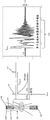
Fig. 13A depicts a graph of experimental data for changes in bias current and temperature as a function of linac beam on time.
FIG. 13B depicts a calibration graph that has been generated by measuring the bias current and the light peak position.
FIG. 13C depicts a plot of the energy resolution of a PET detector over time (each data series interval representing a 10 minute increment with the linac beam turned on at data series value 1 and turned off at data series value 7) with afterglow corrected by gain adjustment.
Fig. 13D depicts the shift in the time resolution centroid over time (each data series interval represents a 10 minute increment with the linac beam turned on at data series value 1 and turned off at data series value 7).
Detailed Description
Some variations of radiation treatment systems may include a treatment radiation source (such as a linear accelerator) and one or more PET detectors (e.g., one or more PET detector arrays) for detecting emissions from positron emitting (i.e., PET-avid) tissue regions. Prior to a treatment session, the patient may be injected with a molecule labeled with radioactive atoms, called a PET radiotracer, and this tracer may preferentially accumulate at one or more tumor regions. Radioactive atoms in the patient decay radiatively and emit positrons. Once emitted from an atom, the positron will rapidly collide with a nearby electron, both of which will then annihilate. Two high-energy photons (511keV) are emitted from the annihilation site and travel in opposite directions. When two photons are detected by two PET detectors simultaneously, the annihilation is known to occur somewhere along the line connecting the two PET detectors. The radiation therapy system may acquire positron emission data before or during the treatment session, and the emission data may be used to direct the radiation of these tumor regions. For example, an emission guided radiation therapy system may include a plurality of PET detectors and a linear accelerator mounted on a gantry that is rotatable about a patient. In some variations, the plurality of PET detectors may include two PET detector arrays disposed on the gantry opposite each other. Emission data acquired by the detector in real time may be analyzed by the system controller to control rotation of the gantry to direct radiation from the linac to the PET-avid tumor region. In some variations, the real-time positron emission data may also be used to update the treatment plan to account for any tumor motion that may occur between treatment planning sessions and treatment sessions.
The PET detector includes a scintillation material (e.g., a scintillation crystal such as bismuth germanium oxide, gadolinium silicate, or lutetium silicate) coupled to a sensor (e.g., any photodetector, photomultiplier tube, such as a silicon photomultiplier tube). When a high-energy photon strikes a PET detector, the energy from the photon causes a scintillation event in the scintillation material, which may generate one or more lower energy (e.g., visible light) photons that are detected by the photodetector device. The photodetector device may have a baseline dark count rate or dark current, where random fluctuations in output may be indistinguishable from fluctuations indicative of the presence of photons. The dark count causes the detector pixel to be excited by the discharge. When a pixel discharges, it draws current from the power supply, and the current drawn from the power supply may be referred to as the bias current. The bias current may be proportional to the average number of dark counts excited over a period of time plus another constant or slowly varying term; that is, the bias current may be proportional to the dark current. The dark current may be proportional to the afterglow light current plus the thermal noise current of the PET photodetector. The bias current may be measured using a current measurement device or module that may be included in the PET detector array. Alternatively or additionally, the bias current may be measured using an ammeter disposed in series with the PET detector photodetector and the power supply. Measuring the bias current and/or change in bias current to the photodetector at a selected or set operating range (e.g., gain and/or sensitivity) may provide an indication of the dark count rate and/or change in dark count rate (i.e., a change in bias current may indicate a shift in dark count rate). For example, as the dark count rate increases, the bias current to the photodetectors of the PET detector may also increase, as more current is drawn from the power supply as a greater number of random fluctuations cause the pixels of the detector to discharge more frequently. Under normal operating conditions, the dark count rate may be relatively low, for example, about 200 thousands of dark counts (cps) per second. Increased ambient temperature and/or increased emission levels can result in increased dark count rates or dark currents of the photodetectors.
The radiation therapy system may include at least two PET detector arrays positioned opposite each other on a gantry. For example, a PET detector on a first array may have a corresponding PET detector on a second array on the opposite side so that two high energy photons from a positron annihilation event may be detected. In one variation, the radiation therapy system may include two PET detector arrays, each including 32 PET detector modules (64 total PET detector modules). Each PET detector module may include a 6 x 12 sub-array of PET detectors, with each PET detector having its own photodetector. In some variations, each PET detector module may measure and output the bias currents of all the photodetectors of the PET detectors in the 6 x 12 array, and the gains of all the photodetectors in the PET detector module may be set by a single gain input value. Since positron emission and annihilation events are random events, the system's PET detectors can detect multiple high-energy photons within a short time interval, and the controller uses the temporal information (e.g., time of detection) of each detected photon along with the location of the PET detector that detected the photon to determine which two photons are part of the positron annihilation photon pair. For example, if two high-energy photons are detected by two PET detectors positioned opposite each other within a particular time interval (e.g., a coincidence time window), the controller can pair the two photons together as originating from the same positron annihilation event occurring somewhere along the line connecting the two PET detectors. A coincidence time window is a time interval within which detected photons can be considered coincident (and processed as if they came from the same positron annihilation event). The coincidence trigger threshold can be a trigger threshold that distinguishes between signals resulting from the detection of annihilation photons and signals resulting from scattered radiation and/or other noise sources (e.g., random detector noise, afterglow, thermal noise, etc.). If the annihilation event is located closer to one of the PET detectors than the other one of the PET detectors, one photon of the pair of photons will have a shorter travel distance than the other photon (i.e., one photon will have a shorter time-of-flight than the other photon) and, therefore, will strike the first PET detector before the second photon strikes the second PET detector. The controller can use the time difference between the detection of photons in the positron annihilation pair to determine the location on the line between two PET detected events at which the annihilation event occurred. PET detectors with sufficient time accuracy to sense the time of flight (TOF) differences of positron annihilation photons can transmit TOF data to a system controller to calculate the location of the positron annihilation event.
During the treatment session, the linac may generate high-flux X-ray pulses that are emitted toward the targeted area. A beam limiting device, such as one or more jaws and/or a collimator (e.g., a multileaf collimator), can help limit the spread of X-rays and direct the X-rays to a targeted tissue region.These X-rays may interact with the patient, where a portion of the X-rays irradiate a targeted region of the patient (e.g., a tumor region) and a portion of the X-rays may be scattered by the patient. The scattered X-rays may interact with components of the radiation therapy system, such as an X-ray detector (e.g., an MV or kV detector) and/or a PET detector. This effect is schematically illustrated in fig. 1A, where the body of the patient 120 may scatter X-rays from the linac 130 and the target 132. The X-rays from the linac and the target may be shaped by a beam limiting device (such as a multi-leaf collimator 134) to form a treatment beam 122. The scattered X-rays or radiation 124 may be incident on a PET detector 126, triggering scintillation events (e.g., lower energy photons) that are indistinguishable from scintillation events caused by positron emission, which are then sensed by photodetectors of the PET detector. Other radiation therapy systems, such as proton therapy systems, may also generate scattered X-rays or neutrons. Scattered radiation from proton sources may also cause excitation of the scintillation crystal. Afterglow of PET detector 126 caused by scattered radiation (and/or other radioactive sources) may accumulate over time and cause the detector to saturate or "blank" for a period of time such that it cannot detect positron emission event data during the blanking interval. FIG. 1B depicts an example of an output trajectory 110 from a PET detector 100, where at tpulse A linac pulse 101 is applied. The linac pulse may have a pulse width of from about 1 μ s to about 10 μ s (e.g., from about 3 μ s to about 5 μ s, about 3 μ s, about 5 μ s, about 8 μ s, etc.), with an inter-pulse interval P of from about 2ms to about 20ms (e.g., from about 4ms to about 10ms, from about 5ms to about 15ms, about 4ms, about 10ms, etc.). fig.intervalAnd/or a pulse frequency from about 100Hz to about 250 Hz. Scattered X-rays/radiation 102 from the linac pulse may irradiate the PET detector 100, generating afterglow photons 104 in the scintillation material 103, which afterglow photons 104 are then detected by a photodetector 105. As seen in output trace 110, the afterglow photons cause a significant amount of short term artifacts in the time period immediately thereafter to about 50 μ s or more (e.g., 100 μ s), during which the PET detector's ability to respond to positron emission events is reduced or degraded (e.g., the PET detector is saturated with electrons)Or the blanking may be a result of photodetector saturation and/or scintillator reaching its maximum photon output and/or electrical and/or magnetic interference from the linac, etc.). This period of time may be referred to as the blanking interval 112 and is a short term effect of detector afterglow. The blanking interval 112 may last from the beginning of the pulse to about 50 mus (or more), depending on, for example, the duration and energy of the linac pulse. After the initial blanking interval 112, the scintillating material of the PET detector may continue to scintillate such that afterglow photons continue to be generated, but possibly at a lower rate than during the blanking interval 112. These afterglow photons can be generated by a continuous excitation and/or increased energy levels of the scintillation material of, for example, a PET detector. The continuous incidence of these afterglow photons on the photodetector 105 may result in a greater level of noise 114 being generated in the output trace 110 after application of the linac pulse than before application of the pulse. This increased level of noise 114 may take about 1-5 hours to decay to the pre-linac pulse level and may be a long term effect of afterglow. In the presence of high levels of scattered radiation, afterglow photons may saturate the photodetector (e.g., silicon photomultiplier tube). Since more than one linac pulse is transmitted during a treatment session (e.g., about 2ms to about 10ms between each pulse), the afterglow noise of later pulses may add to the afterglow noise of previous pulses, which may result in increasingly noisy noise on the output trajectory 110 of the PET detector. This can undermine the ability of the PET detector to acquire accurate and precise positron emission data throughout the duration of one or more treatment sessions. In particular, the ability of a PET detector to perform a time-of-flight analysis with sufficient accuracy to detect coincident positron annihilation photon pairs may be compromised due to short-term or long-term afterglow effects.
Another way in which the afterglow effect can undermine the ability of a PET detector to acquire accurate and precise positron emission data throughout the duration of one or more treatment sessions is from the degradation of the energy resolution of the photodetector. As described above, the photodetector may be saturated by afterglow photons. Photodetectors such as silicon photomultiplier tubes may include hundreds to thousands of discrete geiger avalanche photodiodes (which may be referred to as micro-pixels). Optical photons interacting with a single geiger avalanche photodiode or a micro-pixel may cause the micro-pixel to discharge. After discharge, the micro-pixels take some finite amount of time to recover. The limited amount of time may be from about 10ns to about 100 ns. If there is significant afterglow (e.g., as determined from an elevated bias current exceeding a threshold), the total number of discrete micro-pixels available for detecting positron emission data may be reduced because they are excited from afterglow photons and a scintillation signal produced by positron annihilation photons cannot be detected. As the photodetector saturates with afterglow, its effective or cumulative gain decreases. That is, the signal output from the photodetector that is affected by afterglow for a particular scintillation event is reduced as compared to the signal output from the photodetector under normal (i.e., non-afterglow) conditions. If the gain of the photodetector is reduced, the quantitative accuracy of measuring the total energy of the incident photons (e.g., scintillation events) may be degraded, which may hinder the ability to reject scattered photons. Although the afterglow effect may not degrade the sensitivity of the PET detector, the afterglow effect may reduce the energy quantification accuracy and the timing resolution of each scintillation event.
Afterglow can also cause the photodetector to detect or record positron annihilation photons (i.e., 511keV photons) at a lower energy level; that is, instead of the photopeak of the 511keV photon being at a 511keV energy level on the energy spectrum, the photopeak of the 511keV photon is at a lower energy level than 511 keV. Since the coincidence detection controller or processor is configured to detect positron annihilation events based on 511keV photons (e.g., setting the detection window to be centered at the 511keV energy level), moving the optical peak of the 511keV photons to a lower energy level (e.g., outside of the detection window) may cause the PET detection system controller or processor to miss detection of positron annihilation events.
Method
One method for acquiring positron emission data from a PET detector in the presence of scattered radiation may include adjusting the gain of a PET detector photodetector (e.g., photomultiplier) as the detector afterglow increases, as shown in the flow chart of fig. 2A. As shown here, the method 220 may include setting 222 an initial gain value for a photodetector of a PET detector of the radiation therapy system. This step may be performed during assembly and/or manufacture of the system, or may be performed just prior to the start of the radiation therapy session. After the gain values have been set, the method may include performing 224 radiation therapy, which may include: injecting a PET tracer into a patient; and activating the linac to generate and excite the radiation pulses to the one or more targeted regions. During a radiation treatment session, the system controller may monitor one or more parameters and/or characteristics of the linac and/or PET detector and/or any other detector or sensor (e.g., current or voltage sensor, temperature sensor, radiation sensor, etc.). The controller may determine 226 whether one or more of those characteristics meet a criterion for adjusting a gain value of a photodetector of the PET detector. If one or more criteria for adjusting the gain value have been met, the controller may adjust 228 the gain value of the PET detector, for example, by adjusting a bias voltage of the photodetector and/or by adjusting a gain factor used by a processor of the controller in data acquisition or analysis (e.g., adjusting an acquisition or analysis software gain factor). For example, one or more system parameters exceeding a predetermined threshold may indicate that PET detector afterglow has increased to a certain level, and increasing the gain value of the photodetector and/or the data acquisition gain factor may help reduce false detection of coincident high-energy photons. At increasing levels of afterglow, the scintillating material can generate more photons. These afterglow photons can cause the PET detector photodetector to record the detection of 511keV photons at a lower energy level. That is, the output from the PET detector may indicate that when a 511keV photon is actually detected, a photon of a lower energy level than 511keV is detected, but the output of the PET detector photodetector decreases in size/energy due to afterglow. Increasing the gain value of the photodetectors of the PET detector (e.g., by increasing the bias voltage of the photodetectors) may help to increase the output of the PET detector photodetectors such that they accurately reflect the detection of 511keV photons, which may help to improve the detection rate of truly coincident high energy photons. Alternatively or additionally, the system processor may use a gain factor in compensating for the reduced PET detector output data acquisition. For example, the system processor may multiply and/or offset the output of the PET detector by a gain factor whose value depends on the afterglow level. In some variations, the method depicted in fig. 2A and the methods depicted in fig. 3-7 may be implemented in a set of machine readable instructions that may be stored in a memory of a controller in communication with the PET detector. Data from the radiation therapy system (such as from various sensors, PET detectors, linacs, etc.) may be transmitted to a controller, which may perform calculations (e.g., analyses) based on those measurements and/or may store the results of those calculations and/or system data in one or more controller memories. Command signals generated by the controller may be transmitted to components of the radiation therapy system (e.g., the PET detector and/or the linac) to control operation of those components (e.g., adjust gain values of photodetectors of the PET detector).
A method for acquiring positron emission data from a PET detector in the presence of scattered radiation may comprise: as the afterglow of the detectors increases, the coincidence trigger threshold of the PET detectors is adjusted, as shown in the flow chart of FIG. 2B. As shown herein, the method 200 may include setting 202 an initial coincidence trigger threshold for a PET detector of a radiation therapy system. This step may be performed during assembly and/or manufacture of the system, or may be performed just prior to the start of the radiation therapy session. After the coincidence trigger threshold has been set, the method may include performing 204 radiation therapy, which may include injecting a PET tracer into the patient and activating a linac to generate and excite radiation pulses to one or more targeted regions. During a radiation treatment session, the system controller may monitor one or more parameters and/or characteristics of the linac and/or PET detector and/or any other detector or sensor (e.g., current or voltage sensors, temperature sensors, radiation sensors, etc.). The controller may determine 206 whether one or more of those characteristics meet criteria for adjusting a coincidence trigger threshold of the PET detector. The controller may adjust 208 the coincidence trigger threshold of the PET detector if one or more criteria for adjusting the coincidence trigger threshold have been met. For example, one or more system parameters exceeding a predetermined threshold may indicate that PET detector afterglow has increased to a certain level, and increasing the coincidence trigger threshold may help reduce false detection of coincident high energy photons. That is, at increasing levels of afterglow, the scintillating material can generate more photons. These afterglow photons may degrade or reduce the ability of the PET detector to detect coincident high energy photons. Increasing the coincidence trigger threshold of the PET detector helps to ignore afterglow photons and helps to increase the rate of detection of truly coincident high energy photons. In some variations, the method depicted in fig. 2B and the methods depicted in fig. 3-7 may be implemented in a set of machine readable instructions that may be stored in a memory of a controller in communication with the PET detector. Data from the radiation therapy system (such as from various sensors, PET detectors, linacs, etc.) may be transmitted to a controller, which may perform calculations based on those measurements and/or may store the results of those calculations and/or system data in one or more controller memories. Command signals generated by the controller may be transmitted to components of the radiation therapy system (e.g., the PET detector and/or the linac) to control operation of those components (e.g., adjust coincidence trigger thresholds of the PET detector).
Criteria for PET detector photodetector gain adjustment (e.g., adjusting a gain value of a PET detector photodetector and/or a gain factor used in positron emission data acquisition) and/or coincidence threshold adjustment may be measured across an entire PET detector array and/or PET detector module (i.e., a sub-array with PET detectors) and/or a single PET detector. For example, in a radiation therapy system having two PET detector arrays, each comprising a plurality of PET detector modules (e.g., 32 PET detector modules), each PET detector module comprising a sub-array of PET detectors (e.g., a 6 x 12 sub-array of PET detectors), and each PET detector having its own photodetector, measurements can be made of the standard (and/or temperature, bias current, noise level, coincidence timing distribution, photopeak, dark count rate, etc.) across the entire PET detector array, and/or across the individual PET detector modules, and/or across the individual PET detectors. Similarly, the gain and/or coincidence trigger thresholds may be adjusted for the entire PET detector array and/or individual PET detector modules and/or individual PET detectors. For example, all PET detectors in a PET detector module may have the same photodetector gain value (i.e., the bias voltage applied to the module is applied to all PET detector photodetectors), and the bias current measurement may be the cumulative bias current of all PET detectors in the module. The bias current, bias voltage, and/or gain factor of each PET detector module may be different from one another. That is, different levels of afterglow correction can be applied to different PET detector modules. For example, in a radiation therapy system having two PET detector arrays each having 32 PET detector modules, the afterglow effects of each of the 64 PET detector modules may be corrected by measuring 64 bias currents (and/or temperature, noise level, coincidence timing distribution, light peak, dark count rate, etc.) for the 64 PET detector modules and then applying afterglow corrections to the 64 PET detector modules separately (e.g., applying 64 possibly different gain and/or coincidence threshold adjustments). Alternatively or additionally, bias currents (and/or temperatures, noise levels, coincidence timing distributions, light peaks, dark count rates, etc.) may be measured for individual PET detector photodetectors and/or across an entire PET detector array having a plurality of PET detector modules. Although the following description and variations may refer to measuring bias currents (and/or temperatures, noise levels, coincidence timing distributions, photo-peaks, dark count rates, etc.) for a single PET detector and/or photo-detector (or for multiple PET detectors and/or photo-detectors), and adjusting gains and/or gain factors and/or coincidence thresholds for a single PET detector and/or photo-detector (or multiple PET detectors and/or photo-detectors, respectively), it should be understood that the description is also applicable to measuring multiple bias currents (and/or temperatures, noise levels, coincidence timing distributions, photo-peaks, dark count rates, etc.) for multiple PET detectors and/or photo-detectors (or for individual PET detectors and/or photo-detectors), and adjusting bias currents (and/or temperatures, noise levels, coincidence timing distributions, photo-peaks, dark count rates, etc.) for the multiple PET detectors and/or photo-detectors (or for individual PET detectors and/or photo-detectors, respectively), and adjusting bias currents for the multiple PET detectors and/or photo-detectors (or for individual PET detectors and/or photo-detectors, respectively A gain and/or a gain factor and/or a coincidence threshold.
A variation of the method for acquiring positron emission data in the presence of scattered or stray radiation is depicted in figure 3. The method 300 may include generating 302 a calibration table between detector noise levels and coincidence trigger thresholds of the PET detector. A method of generating a calibration table may include: creating environments that cause different levels or levels of noise on the PET detector; providing a positron emission source (e.g., a positron-emitting seed) that emits positrons at a known rate; and adjusting a coincidence trigger threshold of the PET detector at each noise level until an output of the PET detector corresponds to a predetermined temporal resolution quality or metric. The temporal resolution quality or metric may be determined during manufacture and/or calibration of the radiation therapy system. A time-resolved quality can be measured using a calibration source and the time spectrum of coincident detected photons can be analyzed. For example, a positron emitting point source may have a temporal spectrum that follows a gaussian distribution in which the mean is related to the spatial offset of the point source between PET detectors, while the variance is related to the quality of the time resolving power. One method for quantifying temporal resolution quality may include calculating a full width at half maximum (FWHM) of the temporal spectrum. The method 300 may also include measuring 304 the noise level of the PET detector during the treatment session and comparing 306 the measured noise level to the noise levels in the calibration table to identify a coincident trigger threshold corresponding to the measured noise level. The coincidence trigger threshold may be adjusted 308 based on changes in the measured noise level. For example, the coincidence trigger threshold may increase as the noise level on the PET detector increases. Alternatively or additionally, the method 300 may be used to adjust gain values of PET detector photodetectors and/or gain factors used in positron emission data acquisition (e.g., gain factors used to multiply and/or offset output(s) of PET detector (s)). For example, variations of method 300 may include: the method includes generating a calibration table between detector noise levels and gain values and/or gain factors, measuring noise levels of the PET detector during a treatment session, and comparing the measured noise levels to noise levels in the calibration table to identify a gain value and/or gain factor corresponding to the measured noise levels. The gain value and/or gain factor may be adjusted based on changes in the measured noise level.
Scattered X-rays can interfere with the ability of a PET detector to accurately measure the arrival time of high-energy photons. In the absence of scattered X-rays, the timing accuracy of the PET detector can be characterized by a coincidence timing distribution with a range of timing errors. As described above, the coincidence timing distribution can be measured, for example, by using a point calibration source. Time differences from thousands of coincidence events can be analyzed, and coincidence timing distributions can be merged and/or histogrammed to generate timing distributions. The full width at half maximum (FWHM) of the timing distribution can be used to characterize the timing resolution of the PET detector or the entire PET system. As the level of scattered radiation increases, the coincidence timing distribution can change, such that the timing error range increases. For example, in the absence of X-ray interference, the PET detector may have a coincidence timing distribution such that the timing error range is 300ps FWHM, but in the presence of scattered X-rays, the coincidence timing distribution may change such that the timing error range is 550ps FWHM. A method of acquiring positron emission data in the presence of scattered radiation based on a coincidence timing distribution is depicted in figure 4. The method 400 may include: the method includes measuring 402 a coincidence timing distribution of the PET detectors before the linear accelerator is activated (e.g., before a treatment session, and/or during a manufacturing and/or calibration session), measuring 404 a coincidence timing distribution of the PET detectors during a time period when the linear accelerator has been activated (e.g., during a treatment session), and comparing 406 the coincidence timing distribution measured in step 404 with the coincidence timing distribution measured in step 402. The coincidence trigger threshold of the PET detector can be adjusted 408 if the timing profile changes by more than about 10% as compared to a previously measured timing profile. One method of changing the coincidence trigger threshold is by sending a command to the read circuit (e.g., ASIC) to increase the voltage of the timing comparator. In another approach, the coincidence trigger threshold may be a predetermined number of optical photons counted on a photodetector. In this approach, the coincidence trigger threshold can be adjusted by changing (e.g., increasing or decreasing) the number of photons that need to be detected to signal a coincidence event. Alternatively or additionally, the method 400 may be used to adjust gain values of PET detector photodetectors and/or gain factors used in positron emission data acquisition (e.g., gain factors used to multiply and/or offset output(s) of PET detector (s)). For example, variations of the method 400 may include measuring a coincidence timing distribution of the PET detector prior to activating the linac (e.g., prior to a treatment session, and/or during a manufacturing and/or calibration session), measuring a coincidence timing distribution of the PET detector during a time period when the linac has been activated (e.g., during a treatment session), and comparing the coincidence timing distribution measured during treatment with the coincidence timing distribution measured before treatment. If the timing profile varies by more than about 10% from a previously measured timing profile, the gain value and/or gain factor may be adjusted based on the variation in the timing profile.
Afterglow of the PET detector can cause an increase in the dark count rate of the photodetector, which can interfere with accurate detection of positive electron emission events. Another variation of the method of acquiring positron emission data in the presence of scattered radiation is depicted in figure 5. In this approach, the coincidence trigger threshold may be adjusted based on changes in the dark count rate of the PET photodetectors. The method 500 can include measuring 502 a dark count rate of the PET detector prior to activating the linac (e.g., prior to a treatment session, and/or during a manufacturing and/or calibration session), measuring 504 a dark count rate of the PET detector during a time period when the linac has been activated (e.g., during a treatment session), and comparing 506 the dark count rate measured in step 504 to the dark count rate measured in 502. In some variations, the dark count rate may be measured by measuring a bias current of the photodetector, and the comparison in step 506 may be between the calculated dark count rate based on the bias current and/or the bias current measurement itself. Alternatively or additionally, the dark count rate (i.e., measuring the number of low energy photon triggers) may be measured by counting low photon triggers. The dark count rate may be measured across the entire PET detector array or module/sub-array, and/or may be measured on a per photodetector basis. If the dark count rate measured in steps 504 and 506 deviates from greater than about 2 to about 10Mcps (e.g., about 3Mcps), the coincidence trigger threshold of the PET detector(s) can be adjusted 508. For example, if the dark count rate increases or exceeds a threshold (e.g., exceeds about 2Mcps, exceeds about 3Mcps, and/or exceeds about 10Mcps), the coincidence trigger threshold of the PET detector can be increased. Step 504 and 508 may be repeated throughout the treatment session and/or while using the linac. Alternatively or additionally, the method 500 may be used to adjust gain values of PET detector photodetectors and/or gain factors used in positron emission data acquisition (e.g., gain factors used to multiply and/or offset output(s) of PET detector (s)). For example, variations of the method 500 may include measuring the dark count rate of the PET detector prior to activating the linac (e.g., prior to a treatment session, and/or during a manufacturing and/or calibration session), measuring the dark count rate of the PET detector during a time period when the linac has been activated (e.g., during a treatment session), and comparing the dark count rate measured during treatment to the dark count rate measured prior to treatment. If the dark count rate measured during the treatment deviates from the dark count rate measured before the treatment by more than about 2 to about 10Mcps (e.g., about 3Mcps), the gain value and/or gain factor may be adjusted based on the change in the timing distribution.
The effect of PET detector afterglow can also be measured in the bias current of the photodetector. Changes in bias current may indicate a reduced ability of the PET detector to acquire positron emission data, and adjusting the coincidence trigger threshold (e.g., increasing the coincidence trigger threshold as afterglow effects increase) may help improve the accuracy of the emission data acquisition. A variant of the method for acquiring positron emission data in the presence of scattered radiation is shown in fig. 6A. In this approach, the coincidence trigger threshold may be adjusted based on changes in the bias current of the photodetector. The bias current may be measured by monitoring a voltage source (such as a high voltage supply) of the photodetector. The method 600 can include measuring 602 a bias current of a photodetector prior to linac activation (e.g., prior to a treatment session, and/or during a manufacturing and/or calibration session), measuring 604 a bias current of a photodetector during a time period in which the linac has been activated (e.g., during a treatment session), and comparing 606 the bias current measured in step 604 with the bias current measured in 602. If the bias current measured in steps 604 and 606 deviates by more than about 0.1mA to about 5mA, the coincidence trigger threshold of the PET detector can be adjusted 608. Alternatively or additionally, the bias current may be measured across the entire PET detector array or module/sub-array, and/or may be measured on a per photodetector basis. Step 604 and 608 may be repeated throughout the treatment session and/or while using the linac.
Alternatively or additionally, the coincidence trigger threshold of the PET detector and/or the gain value of the PET detector photo detector and/or the gain factor used in the positron emission data acquisition may be adjusted based on temperature and/or radiation measurements at the linac (or any treatment radiation source) and/or PET detector array, or the region surrounding the linac and/or PET detector array. For example, the radiation therapy system may include one or more temperature sensors, which may be located at or near the PET detector array and/or at or near the linac. Temperature data from these sensors may be transmitted to a controller, and the coincidence trigger threshold of the PET detector may be adjusted if the temperature at the linac and/or PET detector array exceeds one or more thresholds. Similarly, one or more dosimeters (e.g., MOSFET dosimeters, thermoluminescent dosimeters, etc.) may be located at or near the PET detector array and/or at or near the linac. The radiation data from these dosimeters may be transmitted to a controller, and the coincidence trigger threshold of the PET detector may be adjusted if the radiation level at the linac and/or PET detector exceeds one or more thresholds. Some methods may also adjust a coincidence trigger threshold and/or a gain value of a PET detector photodetector and/or a gain factor used in positron emission data acquisition (e.g., a gain factor used to multiply and/or offset the output(s) of the PET detector (s)) based on the radiation output of the linear accelerator. For example, the radiation therapy system may include a dose chamber or an ionization chamber disposed in the beam path of the linac. The ionization chamber may send the amount of radiation emitted by the linac to a controller, which may adjust a coincidence trigger threshold of the PET detector and/or a gain value of the PET detector photodetector and/or a gain factor used in the positron emission data acquisition based on the radiation output of the linac. For example, a table mapping various radiation output thresholds to various coincidence trigger thresholds and/or gain values of the PET detector photodetectors and/or gain factors used in the positron emission data acquisition may be stored in the controller memory, and the controller may compare the real-time ionization chamber measurements to the thresholds in the table to determine whether to adjust the coincidence trigger thresholds and/or gain values of the PET detector photodetectors and/or gain factors used in the positron emission data acquisition. The threshold may be based on the cumulative radiation output from the start of the first pulse emitted by the linac until the current point in time, and/or may be based on the radiation output over a predetermined time interval (e.g., the pulse rate during a treatment session). For example, radiation output levels of the linac to the human torso greater than 0.1Gy/min may generate sufficient levels of scattered radiation that may cause afterglow in a PET detector.
In some variations, a table mapping the linac pulse counts to various coincidence trigger thresholds and/or gain values of the PET detector photodetectors and/or gain factors used in positron emission data acquisition (e.g., gain factors for multiplying and/or offsetting the output(s) of the PET detector (s)) may be stored in the controller memory. The number of radiation pulses emitted by the linac can be used by the controller to adjust the coincidence trigger threshold of the PET detector. For example, the controller may adjust the coincidence trigger threshold of the PET detector after the linac has emitted a first number of pulses (e.g., 10000 pulses). When the linac has emitted an additional number of pulses (e.g., another 10000 pulses, bringing the cumulative pulse count to 20000), the controller may again adjust the coincidence trigger threshold and/or the gain value of the PET detector photodetector and/or the gain factor used in the positron emission data acquisition. The number of pulses emitted by the linac (i.e., the threshold number of radiation pulses) may be about 1000, about 2000, about 4000, about 7500, or about 12000 pulses, etc., depending on the level of scattered or stray radiation present in a particular treatment system, prior to adjusting the coincidence trigger threshold and/or the gain value of the PET detector photodetector and/or the gain factor used in the positron emission data acquisition. That is, for systems with elevated levels of scattered or background radiation, the number of linac pulses may be lower for systems with lower levels of scattered or background radiation before adjusting the coincidence trigger threshold and/or the gain value of the PET detector photodetector and/or the gain factor used in the positron emission data acquisition. In some variations, the table may map the linac pulse rate or pulse schedule (i.e., the number of pulses and/or the timing schedule of pulses within a particular time interval) to a PET detector coincidence trigger threshold and/or a gain value of a PET detector photodetector and/or a gain factor used in positron emission data acquisition. One or more of these parameters may be used alone and/or in combination with one or more of the methods described herein to determine when to adjust the PET detector coincidence trigger threshold and/or the gain value of the PET detector photodetector and/or the gain factor used in the positron emission data acquisition, and/or how much to adjust the coincidence trigger threshold (e.g., increase or decrease a particular value, etc.). As an example, the initial coincidence trigger threshold for a PET detector at the beginning of a treatment session may be about 2 photon triggers. The photon trigger may be a voltage, charge, or count representing the detected photon. For example, a2 photon trigger means that the timing discriminator of the PET detector fires when two or more photons are detected to arrive. After 10000 radiation pulses have been emitted, the coincidence trigger threshold can be increased to about 5 photon triggers. After 10000 radiation pulses have been emitted (that is to say 20000 radiation pulses have been accumulated), the coincidence trigger threshold can be increased to about 6 photon triggers. As desired, the threshold number of radiation pulses before changing the coincidence trigger threshold and the coincidence trigger threshold change increment may vary from this example.
FIG. 6B depicts a variation of a method in which the gain value of the PET detector photodetectors may be adjusted based on changes in the bias current of the photodetectors, which may compensate for saturation of the photodetectors (e.g., silicon photomultiplier tubes) due to afterglow. The bias current may be measured by monitoring a voltage source (such as a high voltage supply) of the photodetector. The method 620 may include: the bias current of the photodetector is measured 622 prior to activation of the linac (e.g., prior to a treatment session, and/or during a manufacturing and/or calibration session), the bias current of the photodetector is measured 624 during a time period when the linac has been activated (e.g., during a treatment session), and the bias current measured in step 624 is compared 626 to the bias current measured in 622. If the bias current measured in steps 624 and 626 deviates by more than about 0.1mA to about 5mA, the gain value of the PET detector photodetector and/or the gain factor used in the positron emission data acquisition may be adjusted 628. The bias current may be measured across the entire PET detector array or module/sub-array, and/or may be measured on a per photodetector basis. Steps 624-628 may be repeated throughout the treatment session and/or while using the linac. In some variations, the gain value of the photodetector(s) may be adjusted by adjusting a bias voltage of the photodetector and/or a gain factor used by a processor of the controller in positron emission data acquisition (e.g., adjusting an acquisition or analysis software gain factor). For example, the system processor may use gain factors in the data acquisition to help compensate for the reduced PET detector output due to afterglow effects. For example, the system processor may multiply and/or offset the output of the PET detector by a gain factor whose value depends on the afterglow level (e.g., as indicated by the measured bias current). The gain factor may be calculated by, for example, measuring the PET detector output values corresponding to 511keV photons (corresponding to different values of the measured bias current) at different afterglow levels, and taking the difference between the measured PET detector output values and the nominal output values corresponding to the detection of 511keV photons (i.e., in the absence of afterglow), and calculating the ratio of the difference to the nominal output values. Alternatively or additionally, the gain factor may be calculated by measuring the photopeak shifts of the 511keV photons at different afterglow levels (corresponding to different values of the measured bias current) and taking the difference between the shifted photopeak(s) and the nominal photopeak at 511keV (i.e., in the absence of afterglow) and calculating the ratio of the difference to each of the shifted photopeaks. A calibration table or graph may be generated that maps the measured bias current to a gain factor value. Changing the gain value and/or gain factor used in the positron emission data acquisition can adjust the energy and timestamp of the positron annihilation event recorded by the PET detector to correct for detector saturation caused by afterglow. In some variations, a method for adjusting a gain value and/or a gain factor may include: a calibration table is generated between the bias current values and the gain values (and/or gain factors), the bias current of the PET detector photodetectors is measured during the treatment session, the measured bias current is compared to the bias current values in the calibration table to identify the gain values and/or gain factors corresponding to the measured bias current, and then the gain values and/or gain factors are adjusted according to the calibration table.
Fig. 13A depicts a graph of experimental data for the change in bias current and temperature as a function of time for a linac beam while keeping the bias voltage constant. As depicted therein, it can be seen that after turning on the beam at time point 0, the bias current increased from a low level of about 0.2mA to about 4.2mA in about one hour. When the beam is turned off at time point 69 (i.e., 69 minutes after the beam is turned on), the bias current will drift back down to its baseline value in about 100 minutes. As the PET detector heats up, the temperature also drifts upward as it must dissipate more power in the photodetector. The heat accumulated in the PET detector may be the bias current multiplied by the bias voltage. In this experiment, the heat generated in the detector started at about 11mW at about one time point 0(0.2mA x 55V), but increased significantly to about 231mW at about the time point 69 of the peak (4.2mA x 55V). The change in temperature also affects the gain value of the photodetector, which can be corrected or compensated for by adjusting a gain factor used in the positron emission data acquisition, as described herein.
A calibration table may be generated by measuring positron emission data for calibrating a positron emission point source (e.g., Na-22) using a PET detector and tracking (i.e., quantifying) how the measurement varies at different levels of afterglow. FIG. 13B depicts a calibration graph (which may be presented as a calibration table) that has been generated by measuring bias current and photopeak position on PET detector modules having a 6 x 12 sub-array of PET detectors. The photopeak is the position of the 511keV peak of the photodetector along the energy spectrum as detected by the PET detector photodetector. The photons emitted by the positron annihilation event have the same energy and, therefore, each significant event has the same energy value. The "photopeak" may be a 511keV peak on the energy spectrum histogram of all detected events. As can be seen in FIG. 13B, as the photodetectors of the PET detectors experience greater afterglow, the bias current increases and a photopeak of 511keV photons is detected, as lower energy photons are detected (e.g., linearly drifting down from 511keV (nominal) to 400 keV). This downward shift of the 511keV photopeak can degrade the performance of the photodetector and hinder its ability to identify or report 511keV photons caused by positron annihilation events. Fig. 13C depicts a plot of energy resolution of the PET detector over time (each data series interval representing a 10 minute increment with the linac beam turned on at data series values 1 and turned off at data series values 7) in which the gain of the PET detector photodetector has been adjusted to compensate for the downward shift of the 511keV photopeak. As depicted there, the energy resolution is kept stable over time by gain adjustment or correction. As previously described, the gain of the photodetector may be adjusted or varied by adjusting the bias voltage of the detector. Alternatively or additionally, a gain factor that may be used by the system processor in data acquisition may be adjusted such that the system processor multiplies and/or offsets the output of the PET detector by the gain factor. In one variation, the gain factor for each bias current value may be the slope of a curve or line-to-bias current plot at that bias current value in the location of the light peak. In the example of fig. 13B, the gain factor may be the slope of a line (fitted to the data points in the graph) and the gain factor may be multiplied by the PET detector module output to identify the positron annihilation event. A calibration table may be generated based on the graph of fig. 13B that maps the measured bias current level to a light peak location on the energy spectrum. Fig. 13C shows the results of applying the gain correction in different afterglow cases. As shown herein, adjusting the gain factor at different afterglow conditions/levels helps to keep the energy resolution or mass of the measured incident photon energy relatively constant. Monitoring the position of the light peak on the energy spectrum (e.g., during a treatment session) can provide an indication as to whether the gain has been adjusted appropriately to compensate for or correct for afterglow effects (e.g., the gain is not too high or too low). For example, instead of or in addition to a calibration table that maps bias current levels to gain values (e.g., bias voltage levels, software gain factors), a calibration table may be generated that maps photopeak locations (e.g., 511keV photopeak locations) to gain values (and/or gain factors used in positron emission data acquisition) such that the gain values and/or gain factors may be adjusted as a function of photopeak locations during treatment.
Another metric that may be used to determine whether the photodetector gain adjustment properly corrects for the afterglow effect is the temporal resolution of the photodetector. The temporal resolution of the photodetector, which represents the minimum time interval between two photon detection events that can be distinguished by the photodetector as two separate events, may shift due to afterglow effects. FIG. 13D depicts the shift in the time resolution centroid over time as the PET detector photodetectors are subjected to the afterglow-causing scattered linac X-rays (each data series interval representing a 10 minute increment where the linac beam is turned on at data series value 1, turned off at data series value 7, and the recovery period is from data series values 8-16). In some variations, the offset value of the timing centroid may be used to predict or estimate the afterglow level. Some methods for adjusting the gain of the photodetector to correct for the effects of afterglow may include calculating a calibration table that maps the offset of the timing centroid offset as a function of the bias current. Alternatively or additionally, a calibration table may be generated that maps timing centroid offsets to gain values (e.g., bias voltage levels, software gain factors). During the treatment session, timing resolution (e.g., timing centroid) can be measured/monitored and an indication can be provided as to whether the gain has been adjusted appropriately to compensate or correct for afterglow effects (e.g., gain is not too high or too low). In some variations, the gain of the PET detector photodetectors may be adjusted to correct for any timing centroid drift.
As previously described, in the presence of scattered radiation, any method for acquiring positron emission data from a PET detector may include measuring and monitoring one or more parameters and/or characteristics in a linear accelerator and/or PET detector and/or any other detector or sensor (e.g., current or voltage sensor, temperature sensor, radiation sensor, etc.) and determining an afterglow level or severity based on these one or more parameters. That is, parameters such as temperature, bias current, radiation emission level, and/or pulse count may serve as a surrogate to quantify afterglow levels or effects. Based on these measurements, the therapy system can change the gain of the PET detector photodetectors by applying changes in bias voltage and/or corrections or changes to gain values used by the processor of the controller in data acquisition or analysis (e.g., adjusting acquisition or analysis software gain factors).
Alternatively or additionally, some methods may include delaying, by the controller, acquisition of PET data during the linac radiation pulse and for a specified time interval after the radiation pulse. Delaying or pausing PET data acquisition and/or transmission during the linac pulse and for a specified time interval after the pulse may help reduce or eliminate storage and processing of positron emission data having afterglow noise and/or radiation pulse artifacts. The amount of radiation artifact created by linac pulses and/or afterglow effects may be greatest during the pulse and the time interval immediately following the pulse, and processing positron emission data with elevated levels of noise or artifacts may lead to false or inaccurate coincidence detection. In some variations, the width of the radiation pulses from the linac may be about 5 μ s or less, and pulsed at a frequency of about 100Hz to about 300 Hz. In this configuration, the duty cycle of the actual beam on time is from about 0.05% to about 0.15% (i.e., the beam off time is from about 99.85% to about 99.95%). The PET detector and/or controller may delay and/or gate acquisition of PET data (e.g., delay and/or gate acquisition of positron emission data during a 5 μ s linac beam pulse) for a period of time during the linac pulse and/or after the linac pulse that has little or no effect on PET sensitivity. For time-of-flight PET systems, reducing or eliminating relatively high noise positron emission data from the time-of-flight calculations may help facilitate more accurate position calculations, and/or may help reduce error margins.
The duration of the delay time interval may be determined based at least in part on an amount of PET detector afterglow, which may be qualitatively and/or quantitatively determined based on one or more of PET detector noise level, detector timing profile, dark count rate, bias current, temperature, ambient radiation level, etc. (including any of the parameters described above). For example, the delay time interval can be from about 85 μ s to about 500 μ s, e.g., at least about 100 μ s, at least about 200 μ s, etc. In some variations, delaying acquisition of the positron emission data by the controller may include: the reception of positron emission data is gated by the controller such that if the data is detected by the PET detector during a specified time interval after the linac pulse, the controller does not store the positron emission data. Alternatively or additionally, the transmission of positron emission data from the PET detector to the controller may be delayed such that PET data detected by the PET detector is not transmitted during a specified time interval after the linear accelerator pulse. For example, during a specified time interval after the linear accelerator pulse, data transfer from the PET detector to the controller may be suspended, and data transfer may be resumed after the specified time interval has elapsed. In some variations, delaying acquisition of positron emission data by the controller may include reading out positron emission data stored by the controller after a specified time interval following the linac pulse. For example, positron emission data may be acquired and stored in the controller memory even during a specified time interval after the linac pulse, however, the controller will not read the positron emission data from the memory until after the specified time interval has elapsed, and the positron emission data stored in the controller memory reflects the data acquired after the specified time interval.
Figure 7A depicts a flow diagram of a variation of a method for gating positron emission data. As shown, method 700 may include measuring 702 an effect of afterglow on a PET detector. The amount of afterglow can be determined qualitatively and/or quantitatively based on one or more metrics described herein, including but not limited to PET detector noise level, detector timing distribution, dark count rate, bias current, temperature, ambient radiation level, and the like. The method 700 may include setting 704 a gate trigger threshold based on the amount of afterglow. The gate trigger threshold is a time interval during which no positron emission data is transmitted from the PET detector and/or no positron emission data is stored by the controller. For example, if any parameter indicative of the afterglow level exceeds a predetermined threshold (e.g., noise level, timing, dark count rate, bias current level, temperature level, emission level), the gate trigger threshold may be increased to pause the communication of positron emission data between the PET detector and the controller for a longer period of time. The gate trigger threshold may be maintained at an increased level until the afterglow returns to the pre-afterglow level of the PET detector (or within about 5% of the pre-afterglow level). The method 700 may further include: positron emission data is gated 706 based on a gate trigger threshold during and/or after the linac pulse. The method 700 may be performed continuously by the controller during a treatment session and/or may be performed at regular intervals. In some variations, the method 700 may further include: the gate trigger threshold is changed or updated from the initial level if the measured afterglow effect exceeds a selected threshold, and/or if the change in afterglow from a previous measurement exceeds a selected threshold. For example, the gate trigger threshold may not be updated if the amount of detector afterglow remains relatively constant during a treatment session. However, if there is a substantial change in the amount of detector afterglow (e.g., an increase or decrease in detector afterglow), the gate trigger threshold may be updated. Gating can increase from about 500 μ s up to about 10 ms. Alternatively, the gate trigger threshold may be kept constant.
FIG. 7B depicts a schematic diagram of one variation of logic circuitry 709 for gating PET data communications between the PET detectors and the processor of the controller. One or more PET detectors 710 (in one or more PET detector arrays) may output data 711 to a comparator 712. The comparator 712 compares the timing characteristics of the positron emission data 711 to a coincidence trigger threshold 720 from the controller's processor 716. As described above, the coincidence trigger threshold 720 can be determined at system start-up (e.g., can be started to a preset default value) and/or can be updated as the system is used for treatment. If the positron emission data is within the coincidence trigger threshold, the positron emission data is output to a gate 714. Gate 714 may be, for example, an and logic gate. The positron emission data may be transmitted to the processor 716 only when a gating signal 718 from the processor to the gate 714 is active (e.g., "high"). The timing of the gate signal 718 may be such that it is inactive (e.g., "low") during the linac pulse and/or during a time interval (e.g., delay time) after the pulse and active (e.g., "high") after the time interval after the linac pulse has elapsed and/or before the linac pulse. FIG. 7C illustrates an example of a timing diagram 730, the timing diagram 730 depicting a straight lineThe timing of the signals between the linac pulses 732, the inversion of the gating signals (which may be considered a "reset" signal), and a common clock signal 736 shared between the linac, PET detector, and processor. In this example, the linac pulse 732 may have a pulse width of about 5 μ s. In the variation shown in timing diagram 730, the build period t is about 10 μ s before the start (i.e., rising edge) of linac pulse 733setupDuring periods, during linac pulse 733, and during time intervals (e.g., delay times) after linac pulse 733 ends (i.e., falling edge), the inversion of gating signal 734 is "high". Linac pulse 733 may be from about 2 μ s to about 15 μ s with a duty cycle of less than about 0.001. Total duration t of inversion of the gating signal to "highgateAnd may be from about 100 mus to about 3 ms. When the inverse of the gating signal is "high", the positron emission data transmission/acquisition is suspended. When the inverse of the gating signal is "low," the transmission/acquisition of positron emission data may be resumed. The duration of the time between pulses of the gating signal (i.e. the inter-pulse period t)interpulse) May be as low as about 1ms, but in some variations the inter-pulse period between linac pulses may be between about 3ms and about 10 ms. As described above, the time interval after the end of the linac pulse 733 may be adjusted based on the degree of PET detector afterglow.
Alternatively or additionally, the system may interleave positron emission data acquisition with radiation therapy delivery (e.g., linac activation). In this method, a PET detector first acquires positron emission data. In some variations, positron emission data from the PET detector may be used to generate an image. The PET detector may be deactivated or disabled after the positron emission data has been acquired and stored (e.g., stored in the controller memory), and/or after a PET image has been generated using the positron emission data. A radiation source (e.g., a linac or proton source) may be activated after the PET detector has been deactivated, and may emit radiation pulses toward a target (e.g., a tumor region). In this interleaved mode, the positron emission data acquisition and the radiotherapy beam emission do not overlap significantly in time. In some variations, the activation of the PET detector and the radiation source may be at 50/50 duty cycles. While this may allow for longer positron emission data acquisition periods, it may extend the overall length of the treatment session.
The PET system may interlock or stop positron emission data acquisition when the afterglow level exceeds a predetermined threshold. In one variation, the bias current of the PET detector photodetectors may be measured, and if the bias current exceeds a predetermined bias current interlock threshold, the PET detector(s) may interlock and stop data acquisition. The system controller may continue to query the bias current at regular intervals, optionally generating a notification to a clinician or technician indicating the bias current level and/or afterglow level. The PET detector(s) may resume data collection (i.e., clear the interlock) when the bias current value is below the interlock release threshold. In some variations, the interlock release threshold may be the same as the interlock threshold, while in other variations, the interlock release threshold may be less than (e.g., lower than) the interlock threshold.
Oscillating scattering shielding case
Some variations of radiation therapy systems may include a movable radiation shield or filter that may be disposed above the PET detector during the radiation pulse and removed from the PET detector after the radiation pulse. The radiation shield or filter may absorb scattered radiation and/or deflect scattered radiation away from the PET detector, which may help reduce the amount of PET detector afterglow. A physical shield or filter that obscures the PET detector during the linac pulse may also help reduce or eliminate back-projection information associated with the linac pulse. In some variations, the shield may conceal the PET detector during the linac pulse and expose the PET detector before or after the linac pulse. Some PET detectors may be concealed for longer than the linac pulse due to inertia associated with the physical shield or filter.
For example, an emission guided radiation therapy system may include a plurality of PET detectors and a linear accelerator mounted on a gantry that is rotatable about a patient. The emission data acquired by the detector in real time may be analyzed by the system controller. Based on this emission data, the system controller can rotate the gantry to direct radiation from the linac to the PET-avid tumor region from various excitation angles. In some variations, the linac and PET detector may be mounted on a rotatable ring or circular gantry, and the patient treatment region may be located along the center of the circular gantry (e.g., along the axis of rotation). The radiation therapy system can include a radiation filter ring, which can include one or more radiation shields or filters. In some variations, the radiation filter ring may include a closed ring structure, while in other variations, the radiation filter ring may include one or more ring segments (e.g., open rings, partial segments or arcs of rings, etc.). The radiation filter ring may be sized to fit within the inner diameter of the first circular gantry. The radiation filter ring may have the same axis of rotation as the first gantry and may move independently of the gantry. In some variations, the radiation filter ring may rotate, while in other variations, the radiation filter ring may oscillate relative to the circular gantry, with the radiation filter ring moving in a lateral direction along the axis of rotation of the gantry into and out of the diameter of the gantry. In some variations, the radiation shield or filter may include one or more radiation blocking or radiopaque components (e.g., panels comprising high-Z material) that may be positioned circumferentially along the radiation filter ring. Other portions of the radiation filter ring may be radiation transmissive or radiation transparent (e.g., including low-Z materials). The radiation blocking portion(s) of the radiation filter ring (i.e., the portion of the radiation filter ring in which the radiation blocking components are located) may have a size and shape that corresponds to the size and shape of the PET sensor array. In a first configuration (e.g., a radiation blocking configuration), the radiation filter ring may be positioned such that the radiation blocking portion is disposed over the PET detector array. In a second configuration (e.g., a radiation transparent configuration), the radiation filter ring may be positioned such that the radiation transparent portion (i.e., the portion of the radiation filter ring without the radiation blocking components) is disposed over the PET detector array. A motion controller coupled to the radiation filter ring (which may be separate and/or independent from the motion controller of the first gantry) may rotate or oscillate the radiation filter ring to transition between the first and second configurations. The motion controller for the radiation filter ring may include an actuator, a motor, and/or a drive mechanism coupled to the filter ring that provides sufficient power to change the position of the filter ring according to a particular time interval or schedule (as described further below). In some variations, the motion controller may include a spring mechanism having one or more springs and an actuator system or mechanism (e.g., a pneumatic or hydraulic actuator, a cam-based motor, a slotted link motor, an electromagnetic actuator, etc.). The spring mechanism may assist the actuator system or mechanism by providing additional power to help accelerate the filter ring movement and/or to counteract any energy loss in the moving system due to friction and/or drag.
In some variations, the rotatable radiation filter ring may be rotated one-half for each linac pulse. Alternatively or additionally, the oscillating radiation filter loop may form a half-cycle for each linac pulse. The oscillating radiation filter ring may be centered over the PET detector array such that its velocity (e.g., its lateral velocity across the PET detector array into and out of the gantry inner diameter) is higher when the radiation blocking portion obscures the PET detector compared to the velocity when the radiation transmitting portion is disposed over the PET detector. The time during which the PET detector array is blocked or shielded by scattered radiation (e.g., a linac pulse) is relatively short compared to the time during which the PET detector array is not blocked. That is, for a given linac pulse duty cycle, the PET detector is in PET data acquisition mode and therefore may not be blocked by the radiation blocking portion of the radiation filter ring. For example, the motion controller may be synchronized with the linac such that it moves the radiation filter ring into the first configuration during a linac pulse (and optionally, during a time period before and/or after the pulse), and it moves the radiation filter ring into the second configuration after the pulse (e.g., during an inter-pulse interval). The duty cycle, pulse width, pulse frequency of the linac pulses may be communicated to the radiation filter loop motion controller such that the radiation filter loop is in the first configuration during the linac pulses. In some variations, the motion controller may oscillate the radiation filter ring to cover several times the PET detector array width in its path. The length of the oscillating displacement of the radiation filter ring (e.g., the circumferential length or arc length swept by the radiation filter ring as it oscillates between the first configuration and the second configuration) may be selected such that it is greater than the width of the PET detector array. This may help reduce the proportion of the PET detector that is occluded when the oscillating radiation filter ring is in the first configuration. For example, an oscillatory displacement having a length that is nine times the width of the PET detector array width conceals only 5% of the available PET events.
Figures 8A-8B depict a variation of a radiation therapy system 800, the radiation therapy system 800 including PET detector arrays 802a, 802B and a rotatable radiation filter ring 804 surrounding an aperture 803 of the system. The rotatable radiation filter ring 804 includes a first radiation blocking portion 806a and a second radiation blocking portion 806 b. The diameter of the rotatable radiation filter ring may be such that it approximates the inside diameter of a circular gantry on which the PET detector array is mounted. In some variations, the diameter of the rotatable radiation filter ring may be less than the inner diameter of the circular gantry. The PET detector arrays 802a, 802b may be positioned relative to each other (e.g., relative to each other such that the center of the first PET detector array 802a is positioned approximately 180 degrees from the center of the second PET detector array 802 b). Similarly, the radiation blocking portions 806a, 806b may also be positioned relative to one another to correspond with the arrangement of the PET detector arrays 802a, 802 b. The lengths of the radiation blocking portions 806a, 806b may be selected such that their circumferential lengths correspond to the circumferential lengths of the PET detector arrays 802a, 802 b. Fig. 8A depicts a first configuration of a rotatable radiation filter ring 804 in which radiation blocking portions 806a, 806b (which may include one or more high-Z materials) are disposed or aligned over PET detector arrays 802a, 802 b. For example, during a linac pulse, the rotatable radiation filter ring may be in this first configuration. Fig. 8B depicts a second configuration of the rotatable radiation filter ring 804 in which the radiation blocking portions 806a, 806B are not disposed over (i.e., misaligned) the PET detector array when the linac is inactive (e.g., not emitting pulses, or within inter-pulse intervals). Fig. 8C is a schematic cross-sectional view of the system 800 of fig. 8A-8B. Fig. 8C depicts the rotatable radiation filter ring in a first configuration, in which the radiation blocking portion is disposed over the PET detector arrays such that the PET detector arrays 802a, 802b are shielded from radiation along the treatment plane 801 through the aperture 803.
Fig. 9A-9B depict schematic cross-sectional views of another variation of a radiation filter ring 900, where instead of rotating the radiation filter ring within the inner diameter of a circular gantry (which may be disposed about aperture 903), the radiation filter ring 900 oscillates laterally into and out of the inner diameter of the circular gantry. The oscillating radiation filter ring 900 may include first and second radiation blocking portions 902a, 902b, which may have a size and shape corresponding to the size and shape of the PET detector arrays 904a, 904 b. Fig. 9A depicts a first configuration of an oscillating radiation filter ring 900 in which the oscillating radiation filter ring is positioned within the inner diameter of the circular gantry (i.e., the radiation blocking portion is disposed above the PET detector array). As described above, the radiation blocking portion may include one or more panels of high-Z material for reflecting and/or absorbing scattered radiation, and when disposed over the PET detector array may help reduce afterglow of the PET detector by reducing or eliminating incidence of scattered radiation on the PET detector. Fig. 9B depicts a second configuration of the oscillating radiation filter ring in which the radiation blocking portions 902a, 902B are not disposed over (i.e., misaligned with) the PET detector array. The lateral movement of the oscillating radiation filter ring is indicated by arrow 901. During the linac pulse, the oscillating radiation filter ring may be in a first configuration such that the PET detector arrays 904a, 904b are shielded from radiation along the processing plane 901 through the aperture 903, and may be in a second configuration when the linac is inactive (e.g., not emitting pulses or within inter-pulse intervals).
While the above-described variations of the rotatable or oscillating radiation filter ring are circular or annular, in other variations the radiation filter may be a block of radiation blocking or radiopaque material that moves over the PET detector during time intervals when high levels of scattered radiation are desired and away from the PET detector during time intervals when relatively low levels of scattered radiation are desired. For example, the radiation filter may be mounted on an arm, rail, or the like and/or may be coupled to an actuator or motor that moves them over or away from the PET detector.
Examples of the invention
FIG. 10A depicts one example of an experimental setup in which PET detector afterglow is measured and characterized. Short and long term afterglow of PET detectors is measured. An acrylic scattering target 1000 was used to scatter radiation from the 6MeV linac 1002. Target 1000 is a 40cm x 20cm block of acrylic. The PET detectors 1004 are used to measure scattered radiation incident on two PET detectors operating simultaneously to simulate radiation scatter of the patient. The center of the target 1000 was 53cm from the PET detector 1004. The 6MeV linac 1002 generated a 10cm by 10cm X-ray radiation field at 153Hz with a 3us pulse width on an acrylic phantom 1000. The entire device is surrounded by a plurality of lead blocks 1006, each lead block having a length of about 20 cm. In the path of the linac beam 1010 there is a first dose chamber 1008, a second dose chamber 1008 located behind the PET detector 1004, and a dose chamber 1008 located on the wall of the target 1000 furthest from the linac 1002. The membrane 1009 is located on the wall of the target 1000 closest to the linac 1002. FIG. 10B is a schematic diagram of two single crystal PET detectors 1012 (with LYSO scintillation crystals) and 1014 (with LFS scintillation crystals) for use with the apparatus of FIG. 10A. Both PET detectors 1012, 1014 use a solid state photodetector or photomultiplier 1016 (e.g., an mppc (sipm) photodetector), which solid state photodetector or photomultiplier 1016 is capable of time-of-flight measurements and for measuring the effect of scattered radiation on PET data acquisition.
Silicon photomultipliers (sipms) used in PET detectors can be characterized by their dark-rate performance. Sipms can be sensitive to single photons, and dark counts are hot electron noise events in the detector. The scintillation detectors produce short-term afterglow, and these generate photons that persist between scintillation pulses. From the perspective of the detection system, these approximate dark counts. The Dark Count Rate (DCR) of the sensor is characterized as a function of when it occurs relative to the LINAC pulse (fig. 10C). The DCR just before the linac pulse and the DCR 50 to 200 mus after the linac pulse were characterized. Based on these analyses, the controller delays the PET data acquisition by about 200 μ s, which about 200 μ s helps to reduce the DCR to acceptable levels.
The initial DCR of the photosensor was 2M dark counts per second. This matches the specifications provided by the equipment supplier. FIG. 10D depicts DCR as a function of total time of exposure to the linac for LYSO scintillation crystals. As the linac is pulsed, the smallest DCR is just before the linac pulse, as expected (fig. 10D, bottom trace). The DCR is significantly higher if it is measured immediately after the linac pulse. Thus, there is a short constant attenuation, which contributes to afterglow.
Fig. 10E depicts for two different crystals: LFS and LYSO, DCR as a function of total exposure time of the linear accelerator for LYSO scintillation crystals. The linac was continuously operated for 3600 seconds or 1 hour. Afterglow tends to accumulate in the scintillation crystal as the linac operates over time. This afterglow cannot be distinguished from the dark count of the sensor. It significantly degrades the signal-to-noise ratio of the SiPM. Note that the sensor starts with a DCR of about 2M dark counts/second. After 1 hour afterglow, increase to dark counts above 10M per second, or worse 5 times.
FIG. 11 depicts another example of an experimental setup for measuring afterglow using two polysilicon PET detectors.
Fig. 12 depicts a graph of the transit time PET module at various points in time after a linac pulse, where each curve depicts time resolution at a different coincidence trigger threshold. As shown, the afterglow noise can be mitigated by increasing the threshold of the PET detector module (FIG. 11). The afterglow effect can be mitigated by changing the trigger threshold of the PET detector electronics. It may be possible to measure the DCR of the system during treatment and adjust the threshold to help improve the timing performance of the system.
The radiation therapy system described herein can include a controller having a processor and one or more memories. The controller may include one or more processors and one or more machine-readable memories in communication with the one or more processors. The controller may be connected to the radiation therapy system and/or other systems through wired or wireless communication channels. In some variations, the controller of the radiation therapy system may be located in the same or different room as the patient. For example, the controller may be coupled to a patient platform or disposed on a cart or medical cart adjacent to the patient and/or operator.
The controller may be implemented in association with numerous general purpose or special purpose computing systems or configurations. Various exemplary computing systems, environments, and/or configurations that may be suitable for use with the systems and devices disclosed herein may include, but are not limited to, software or other components embodied within or on a personal computing device, a network device, a server or server computing device, such as routing/connection components, portable (e.g., handheld) or laptop computer devices, multiprocessor systems, microprocessor-based systems, and distributed computing networks.
Examples of portable computing devices include smartphones, Personal Digital Assistants (PDAs), cell phones, tablet computers, tablet phones (personal computing devices larger than smartphones but smaller than tablet computers), wearable computers in the form of smartwatches, portable music devices, and so forth.
In some embodiments, a processor may be any suitable processing device configured to execute and/or execute a set of instructions or code and may include one or more data processors, image processors, graphics processing units, physical processing units, digital signal processors, and/or central processing units. The processor may be, for example, a general purpose processor, a Field Programmable Gate Array (FPGA), an Application Specific Integrated Circuit (ASIC), or the like. The processor may be configured to run and/or execute application processes and/or other modules, processes and/or functions associated with the system and/or networks associated therewith. Basic device technologies may be provided in a variety of component types, for example, Metal Oxide Semiconductor Field Effect Transistor (MOSFET) technologies such as Complementary Metal Oxide Semiconductor (CMOS), bipolar technologies such as Emitter Coupled Logic (ECL), polymer technologies (e.g., silicon-conjugated polymers and metal-conjugated polymer-metal structures), analog and digital hybrids, and so forth.
In some embodiments, the memory may include a database, and may be, for example, Random Access Memory (RAM), memory buffers, hard drives, erasable programmable read-only memory (EPROM), electrically erasable read-only memory (EEPROM), read-only memory (ROM), flash memory, and the like. The memory may store instructions to cause the processor to perform modules, processes, and/or functions associated with the system, such as one or more of treatment planning, imaging data acquired in a previous treatment session and/or a current treatment session (e.g., real-time imaging data), biological activity, physiological and/or anatomical data extracted from the imaging data, updated or adjusted treatment planning, updated or adjusted dose delivery instructions, radiation treatment system instructions (e.g., that may direct the operation of the gantry, therapeutic radiation source, multi-leaf collimator, PET detector, and/or any other component of the radiation treatment system), and image and/or data processing associated with treatment delivery.
Some embodiments described herein relate to a computer storage product with a non-transitory computer-readable medium (which may also be referred to as a non-transitory processor-readable medium) having instructions or computer code thereon for performing various computer-implemented operations. The computer-readable medium (or processor-readable medium) is non-transitory in the sense that the computer-readable medium does not include a transitory propagating signal per se (e.g., a propagating electromagnetic wave carrying information on a transmission medium such as space or cable). The media and computer code (also can be referred to as code or algorithms) may be designed and constructed for one or more specific purposes. Examples of non-transitory computer readable media include, but are not limited to: magnetic storage media such as hard disks, floppy disks, and magnetic tape; optical storage media such as compact discs/digital video discs (CD/DVD); compact disc read only memory (CD-ROM) and holographic devices; magneto-optical storage media such as optical disks; solid state storage devices, such as Solid State Drives (SSDs) and Solid State Hybrid Drives (SSHDs); a carrier signal processing module; and hardware devices that are specially configured to store and execute program code, such as Application Specific Integrated Circuits (ASICs), Programmable Logic Devices (PLDs), Read Only Memory (ROM) and Random Access Memory (RAM) devices. Other embodiments described herein relate to a computer program product that may include, for example, the instructions and/or computer code disclosed herein.
The user interface may serve as a communication interface between an operator or clinician and the treatment planning system. The user interface may include an input device and an output device (e.g., a touchscreen and a display) and be configured to receive input data and output data from one or more of the support arm, the external magnet, the sensor, the delivery device, the input device, the output device, the network, the database, and the server. Sensor data from one or more sensors may be received by a user interface and output by one or more output devices visually, audibly, and/or through tactile feedback. As another example, a user may receive operator controls of an input device (e.g., joystick, keyboard, touch screen) and then be processed by the processor and memory for a user interface to output control signals to one or more support arms, external magnets, intraluminal devices, and delivery devices.
In some variations, the output device may include a display device including at least one of a Light Emitting Diode (LED), a Liquid Crystal Display (LCD), an electroluminescent display (ELD), a Plasma Display Panel (PDP), a Thin Film Transistor (TFT), an Organic Light Emitting Diode (OLED), an electronic paper/electronic ink display, a laser display, and/or a holographic display.
In some variations, the radiation therapy system may communicate with other computing devices via, for example, one or more networks, each of which may be any type of network (e.g., wired network, wireless network). A wireless network may refer to any type of digital network that is not connected by any type of cable. Examples of wireless communications in a wireless network include, but are not limited to, cellular, radio, satellite, and microwave communications. However, wireless networks may be connected to wired networks to interface with the internet, other carrier voice and data networks, service networks, and personal networks. Wired networks are typically carried by twisted copper pairs, coaxial cables, and/or fiber optic cables. There are many different types of wired networks, including Wide Area Networks (WANs), Metropolitan Area Networks (MANs), Local Area Networks (LANs), internet access area networks (ias), Campus Area Networks (CANs), Global Area Networks (GANs), such as the internet, and Virtual Private Networks (VPNs). Hereinafter, a network refers to any combination of wireless, wired, public, and private data networks interconnected typically by the internet to provide a unified networking and information access system.
Cellular communication may encompass technologies such as GSM, PCS, CDMA or GPRS, W-CDMA, EDGE or CDMA2000, LTE, WiMAX, and 5G network standards. Some wireless network deployments incorporate networks from multiple cellular networks, or use a mix of cellular, Wi-Fi, and satellite communications. In some embodiments, the systems, apparatus, and methods described herein may include radio frequency receivers, transmitters, and/or optical (e.g., infrared) receivers and transmitters to communicate with one or more devices and/or networks.
Claims (36)
1. A radiation therapy system comprising:
a radiation source configured to direct one or more radiation pulses to a PET-avid region of interest;
a plurality of PET detectors, wherein the plurality of PET detectors are configured to detect positron annihilation photons;
a current detector configured to measure bias currents of the plurality of PET detectors; and
a controller configured to receive photon data outputs from the plurality of PET detectors, wherein the controller is configured to detect coincident positron annihilation photon pairs by adjusting the photon data outputs using a gain factor calculated based on a bias current measured during a treatment session.
2. The system of claim 1, wherein the controller is configured to adjust the gain factor when the bias current exceeds a threshold bias current value.
3. The system of claim 1, wherein the gain factor is a ratio between a measured bias current and a magnitude of the detected photopeak shift of the positron annihilation photon in the photon data output.
4. The system of claim 1, wherein adjusting the photon data output comprises: multiplying the photon data output by the gain factor or linearly offsetting the photon data output by the gain factor.
5. The system of claim 1, wherein the controller is configured to adjust the gain factor after a threshold number of radiation pulses have been directed to the PET-avid region of interest.
6. The system of claim 5, wherein the threshold number of radiation pulses is 1000 radiation pulses.
7. The system of claim 5, wherein the gain factor is a first gain factor and the threshold number of radiation pulses is a first threshold number of radiation pulses, and wherein the controller is configured to adjust the first gain factor to a second gain factor after a second threshold number of radiation pulses have been directed to the PET-avid region of interest.
8. The system of claim 7, wherein the second gain factor is greater than the first gain factor and the second threshold number of radiation pulses is greater than the first threshold number of radiation pulses.
9. The system of claim 1, wherein the controller is configured to calculate a photopeak position of annihilation photons based on the photon data outputs from the plurality of PET detectors, and to adjust the gain factor based on a shift of the photopeak position from a baseline level.
10. The system of claim 1, wherein the controller is configured to adjust the gain factor when a dark count rate of one or more of the plurality of PET detectors exceeds a threshold dark count rate.
11. The system of claim 10, wherein the threshold dark count rate is from 3Mcps to 10 Mcps.
12. The system of claim 2, wherein the threshold bias current value is from 0.1mA to 1 mA.
13. The system of claim 1, wherein the controller is configured to adjust the gain factor when an amount of radiation emitted from the radiation source exceeds a threshold radiation level.
14. The system of claim 13, wherein the threshold radiation level is from 0.1cGy/min to 1 cGy/min.
15. The system of claim 1, wherein the controller further comprises a signal processor and a switch configured to selectively communicate the PET detector output signal to the signal processor, wherein the switch is configured to pause communication of the PET detector output signal to the signal processor for a predetermined period of time after each radiation pulse, wherein a ratio of the predetermined period of time to a duration of each radiation pulse is between 25: 1 to 100: 1.
16. The system of claim 15, wherein the controller is configured to pause the communication of the PET detector output signals to the signal processor for the duration of each radiation pulse and for the predetermined period of time after each radiation pulse.
17. The system of claim 16, wherein the controller is configured to suspend communication of the PET detector output signals to the signal processor based on a gating signal.
18. The system of claim 17, wherein the gating signal causes the controller to pause communication of the PET detector output signals to the signal processor for 100 μ β or more after each radiation pulse.
19. The system of claim 18, wherein the gating signal causes the controller to pause communication of the PET detector output signals to the signal processor for 200 μ β or more after each radiation pulse.
20. The system of claim 5, wherein the controller is configured to adjust the gain factor based at least in part on a timing schedule of the radiation pulses.
21. A method for automatically adjusting PET detector gain for detecting coincident positron annihilation photons, the method comprising:
detecting bias currents of the two or more PET detectors during the treatment session while activating the radiation source;
calculating a gain factor based on the measured bias current; and
the photon data outputs from the two or more PET detectors are adjusted by the calculated gain factors to detect coincident positron annihilation photon pairs.
22. The method of claim 21, further comprising determining whether the measured bias current meets or exceeds a threshold bias current value, and calculating the gain factor when the measured bias current meets or exceeds the threshold bias current value.
23. The method of claim 21, wherein calculating the gain factor comprises calculating a ratio between the measured bias current and a magnitude of the detected photopeak shift of the positron annihilation photon in the photon data output.
24. The method of claim 21, wherein adjusting the photon data outputs comprises multiplying the photon data outputs by the gain factor or linearly offsetting the photon data outputs by the gain factor.
25. The method of claim 21, further comprising determining whether the activated radiation source applies a threshold number of radiation pulses toward a region of interest, and calculating the gain factor when the number of radiation pulses meets or exceeds the threshold number.
26. The method of claim 25, wherein the threshold number of radiation pulses is 1000 radiation pulses.
27. The method of claim 22, wherein the gain factor is a first gain factor, the measured bias current is a first bias current value, and the threshold bias current value is a first threshold bias current value, and wherein the method further comprises measuring a second bias current value, determining whether the second bias current value meets or exceeds a second threshold bias current value, and calculating a second gain factor based on the second bias current value when the second bias current value meets or exceeds the second threshold bias current value.
28. The method of claim 27, wherein the second gain factor is greater than the first gain factor and the second threshold bias current value is greater than the first threshold bias current value.
29. The method of claim 21, further comprising calculating a photopeak position of positron annihilation photons based on the photon data outputs from the two or more PET detectors, and wherein the gain factor is calculated based on a shift of the photopeak position from a baseline level.
30. The method of claim 21, further comprising determining whether a dark count rate of the two or more PET detectors meets or exceeds a threshold dark count rate, and calculating the gain factor when the dark count rate meets or exceeds the threshold dark count rate.
31. The method of claim 30, wherein the threshold dark count rate is from 3Mcps to 10 Mcps.
32. The method of claim 22, wherein the threshold bias current value is from 0.1mA to 1 mA.
33. The method of claim 21, further comprising determining whether an amount of radiation emitted from the activated radiation source meets or exceeds a threshold radiation level, and calculating the gain factor when the amount of emitted radiation meets or exceeds the threshold radiation level.
34. The method of claim 33, wherein the threshold level of radiation is from 0.1cGy/min to 1 cGy/min.
35. The method of claim 25, wherein the gain factor is calculated based at least in part on a timing schedule of the radiation pulses emitted by the activated radiation source.
36. The method of claim 21 wherein detecting the coincident photon annihilation pair occurs 100 μ β or more after the radiation source emits a radiation pulse.
Priority Applications (1)
| Application Number | Priority Date | Filing Date | Title |
|---|---|---|---|
| CN202210276868.9A CN114699655A (en) | 2017-07-11 | 2018-07-11 | Method for persistence management of PET detectors |
Applications Claiming Priority (3)
| Application Number | Priority Date | Filing Date | Title |
|---|---|---|---|
| US201762531260P | 2017-07-11 | 2017-07-11 | |
| US62/531,260 | 2017-07-11 | ||
| PCT/US2018/041700 WO2019014387A1 (en) | 2017-07-11 | 2018-07-11 | Methods for pet detector afterglow management |
Related Child Applications (1)
| Application Number | Title | Priority Date | Filing Date |
|---|---|---|---|
| CN202210276868.9A Division CN114699655A (en) | 2017-07-11 | 2018-07-11 | Method for persistence management of PET detectors |
Publications (2)
| Publication Number | Publication Date |
|---|---|
| CN111050849A CN111050849A (en) | 2020-04-21 |
| CN111050849B true CN111050849B (en) | 2022-04-08 |
Family
ID=64998909
Family Applications (2)
| Application Number | Title | Priority Date | Filing Date |
|---|---|---|---|
| CN201880057036.XA Active CN111050849B (en) | 2017-07-11 | 2018-07-11 | Method for persistence management of PET detectors |
| CN202210276868.9A Pending CN114699655A (en) | 2017-07-11 | 2018-07-11 | Method for persistence management of PET detectors |
Family Applications After (1)
| Application Number | Title | Priority Date | Filing Date |
|---|---|---|---|
| CN202210276868.9A Pending CN114699655A (en) | 2017-07-11 | 2018-07-11 | Method for persistence management of PET detectors |
Country Status (5)
| Country | Link |
|---|---|
| US (4) | US10795037B2 (en) |
| EP (2) | EP3651851B1 (en) |
| JP (2) | JP2020526314A (en) |
| CN (2) | CN111050849B (en) |
| WO (1) | WO2019014387A1 (en) |
Families Citing this family (14)
| Publication number | Priority date | Publication date | Assignee | Title |
|---|---|---|---|---|
| US8017915B2 (en) | 2008-03-14 | 2011-09-13 | Reflexion Medical, Inc. | Method and apparatus for emission guided radiation therapy |
| WO2018093933A1 (en) | 2016-11-15 | 2018-05-24 | Reflexion Medical, Inc. | System for emission-guided high-energy photon delivery |
| CN108109182B (en) * | 2016-11-24 | 2021-08-24 | 上海东软医疗科技有限公司 | PET image reconstruction method and device |
| WO2018183748A1 (en) | 2017-03-30 | 2018-10-04 | Reflexion Medical, Inc. | Radiation therapy systems and methods with tumor tracking |
| CN111050849B (en) | 2017-07-11 | 2022-04-08 | 反射医疗公司 | Method for persistence management of PET detectors |
| CN111148471B (en) | 2017-08-09 | 2023-08-22 | 反射医疗公司 | System and method for fault detection in emission guided radiation therapy |
| US11369806B2 (en) | 2017-11-14 | 2022-06-28 | Reflexion Medical, Inc. | Systems and methods for patient monitoring for radiotherapy |
| US10926111B2 (en) * | 2019-03-21 | 2021-02-23 | Vieworks Co., Ltd. | Bragg peak detector using scintillators and method of operating the same |
| US10682115B1 (en) * | 2019-05-02 | 2020-06-16 | Siemens Medical Solutions Usa, Inc. | Light weight positron emission tomography phantom |
| JP7352720B2 (en) * | 2019-07-23 | 2023-09-28 | フラマトム・ゲーエムベーハー | Methods and dose monitoring systems for optimizing aviation radiation |
| CN110568468B (en) * | 2019-08-27 | 2023-01-10 | 福州智元仪器设备有限公司 | Radiation pulse counting mutation algorithm |
| JP7430044B2 (en) * | 2019-09-17 | 2024-02-09 | 住友重機械工業株式会社 | radiation therapy equipment |
| US20220011450A1 (en) * | 2020-07-13 | 2022-01-13 | Osi Optoelectronics, Inc. | Systems and Methods for Shutterless Afterglow Measurement |
| US11754484B2 (en) * | 2020-09-22 | 2023-09-12 | Honeywell International Inc. | Optical air data system fusion with remote atmospheric sensing |
Family Cites Families (386)
| Publication number | Priority date | Publication date | Assignee | Title |
|---|---|---|---|---|
| US3767883A (en) | 1962-03-20 | 1973-10-23 | Gen Electric | Control and power supply systems for magnetron devices |
| US3418475A (en) | 1965-08-19 | 1968-12-24 | Claude R. Hudgens | Leaf spring-mounted shutter device activated by the interruption of electrical power |
| US3668399A (en) | 1969-06-30 | 1972-06-06 | Ohmart Corp | Gauge using environment-insensitive radiation beam cross-section limiter |
| US3794840A (en) | 1972-03-27 | 1974-02-26 | Charlotte Memorial Hospital | Method and apparatus for directing a radiation beam toward a tumor or the like |
| US3869615A (en) | 1973-06-28 | 1975-03-04 | Nasa | Multiplate focusing collimator |
| US3906233A (en) | 1973-10-12 | 1975-09-16 | Varian Associates | System and method for administering radiation |
| JPS5686400A (en) | 1979-12-14 | 1981-07-14 | Shimadzu Corp | Collimater for radial tomogram device |
| US4361902A (en) | 1980-07-07 | 1982-11-30 | General Electric Company | Collimator for x-ray diagnostic apparatus |
| US4503331A (en) | 1982-04-21 | 1985-03-05 | Technicare Corporation | Non-circular emission computed tomography |
| US4529882A (en) | 1982-08-09 | 1985-07-16 | E. I. Du Pont De Nemours & Company | Compton scattering gamma radiation camera and method of creating radiological images |
| JPS5946571A (en) | 1982-09-09 | 1984-03-15 | Agency Of Ind Science & Technol | Positron ct apparatus |
| US4563582A (en) | 1984-05-24 | 1986-01-07 | Clayton Foundation For Research | Positron emission tomography camera |
| US4642464A (en) | 1984-05-24 | 1987-02-10 | Clayton Foundation For Research | Positron emission tomography camera |
| US4628499A (en) | 1984-06-01 | 1986-12-09 | Scientific-Atlanta, Inc. | Linear servoactuator with integrated transformer position sensor |
| US4677299A (en) | 1985-05-13 | 1987-06-30 | Clayton Foundation For Research | Multiple layer positron emission tomography camera |
| US4647779A (en) | 1985-05-13 | 1987-03-03 | Clayton Foundation For Research | Multiple layer positron emission tomography camera |
| US4771785A (en) | 1986-07-25 | 1988-09-20 | Resonex, Inc. | Magnetic resonance imaging apparatus and three-axis patient positioning assembly for use therewith |
| US4868843A (en) | 1986-09-10 | 1989-09-19 | Varian Associates, Inc. | Multileaf collimator and compensator for radiotherapy machines |
| JPH01156830A (en) | 1987-12-15 | 1989-06-20 | Matsushita Electric Ind Co Ltd | Operating system |
| US4917344A (en) | 1988-04-07 | 1990-04-17 | Loma Linda University Medical Center | Roller-supported, modular, isocentric gantry and method of assembly |
| EP0365660B2 (en) | 1988-04-22 | 2000-01-19 | Analogic Corporation | X-ray tomography apparatus having a position detector |
| JPH0462492A (en) | 1990-06-29 | 1992-02-27 | Toshiba Corp | Nuclear medical diagnostic device |
| US5099505A (en) | 1990-07-02 | 1992-03-24 | Varian Associates | Method for increasing the accuracy of a radiation therapy apparatus |
| US5168532A (en) | 1990-07-02 | 1992-12-01 | Varian Associates, Inc. | Method for improving the dynamic range of an imaging system |
| US5117445A (en) | 1990-07-02 | 1992-05-26 | Varian Associates, Inc. | Electronically enhanced x-ray detector apparatus |
| US5075554A (en) | 1990-09-27 | 1991-12-24 | Siemens Gammasonics, Inc. | Scintillation camera gantry supporting a plurality of detector heads between two parallel plates |
| US5207223A (en) | 1990-10-19 | 1993-05-04 | Accuray, Inc. | Apparatus for and method of performing stereotaxic surgery |
| DK257790D0 (en) | 1990-10-26 | 1990-10-26 | 3D Danish Diagnostic Dev A S | GANTRY FOR GAMMA CAMERA FOR CARDIOLOGICAL EXAMINATIONS |
| US6184530B1 (en) | 1991-05-23 | 2001-02-06 | Adac Laboratories | Adjustable dual-detector image data acquisition system |
| US5317616A (en) | 1992-03-19 | 1994-05-31 | Wisconsin Alumni Research Foundation | Method and apparatus for radiation therapy |
| US5351280A (en) | 1992-03-19 | 1994-09-27 | Wisconsin Alumni Research Foundation | Multi-leaf radiation attenuator for radiation therapy |
| US5661773A (en) | 1992-03-19 | 1997-08-26 | Wisconsin Alumni Research Foundation | Interface for radiation therapy machine |
| JPH0779813B2 (en) | 1992-03-24 | 1995-08-30 | 潤 池辺 | Radiation therapy equipment |
| US5390225A (en) | 1992-06-29 | 1995-02-14 | Siemens Medical Systems, Inc. | Mapping slices of the human body into regions having a constant linear attenuation coefficient for correcting images acquired during a nuclear medicine study for attenuation artifacts |
| US5272344A (en) | 1992-11-10 | 1993-12-21 | General Electric Company | Automated coincidence timing calibration for a pet scanner |
| WO1994028971A2 (en) | 1993-06-09 | 1994-12-22 | Wisconsin Alumni Research Foundation | Radiation therapy system |
| US5418827A (en) | 1993-06-18 | 1995-05-23 | Wisconsin Alumino Research Foundation | Method for radiation therapy planning |
| US5396534A (en) | 1993-10-12 | 1995-03-07 | Thomas; Howard C. | Shutter apparatus for collimating x-rays |
| US5473657A (en) | 1994-02-08 | 1995-12-05 | Analogic Corporation | X-ray tomographic scanning system |
| US5588430A (en) | 1995-02-14 | 1996-12-31 | University Of Florida Research Foundation, Inc. | Repeat fixation for frameless stereotactic procedure |
| US5523571A (en) | 1995-03-31 | 1996-06-04 | Siemens Medical Systems, Inc. | Versatile reconfigurable gantry for use in scintillation camera systems |
| US5668371A (en) | 1995-06-06 | 1997-09-16 | Wisconsin Alumni Research Foundation | Method and apparatus for proton therapy |
| DE19525811A1 (en) | 1995-07-15 | 1997-01-16 | Sauerwein Isotopen Tech | X=ray image system with varying pixel supply voltages for zoom control - uses amorphous silicon photodiode detectors with means for choice of different image recording speed and corresp. resolution |
| US5813985A (en) | 1995-07-31 | 1998-09-29 | Care Wise Medical Products Corporation | Apparatus and methods for providing attenuation guidance and tumor targeting for external beam radiation therapy administration |
| DE29623957U1 (en) | 1995-09-28 | 2001-03-22 | Brainlab Ag | Lamellar collimator for radiation therapy |
| DE19536804A1 (en) | 1995-10-02 | 1997-04-03 | Deutsches Krebsforsch | Contour collimator for radiation therapy |
| GB9520564D0 (en) | 1995-10-07 | 1995-12-13 | Philips Electronics Nv | Apparatus for treating a patient |
| JPH09122110A (en) | 1995-10-31 | 1997-05-13 | Shimadzu Corp | X-ray ct system |
| US5818902A (en) | 1996-03-01 | 1998-10-06 | Elekta Ab | Intensity modulated arc therapy with dynamic multi-leaf collimation |
| US6260005B1 (en) | 1996-03-05 | 2001-07-10 | The Regents Of The University Of California | Falcon: automated optimization method for arbitrary assessment criteria |
| US5946425A (en) * | 1996-06-03 | 1999-08-31 | Massachusetts Institute Of Technology | Method and apparatus for automatic alingment of volumetric images containing common subject matter |
| US5851182A (en) | 1996-09-11 | 1998-12-22 | Sahadevan; Velayudhan | Megavoltage radiation therapy machine combined to diagnostic imaging devices for cost efficient conventional and 3D conformal radiation therapy with on-line Isodose port and diagnostic radiology |
| US5917882A (en) | 1996-11-29 | 1999-06-29 | Continental X-Ray Corporation | Radiographic/fluoroscopic imaging system with reduced patient dose and faster transitions between radiographic and fluoroscopic modes |
| US6023494A (en) | 1996-12-19 | 2000-02-08 | General Electric Company | Methods and apparatus for modifying slice thickness during a helical scan |
| US5841140A (en) | 1997-01-08 | 1998-11-24 | Smv America, Inc. | Gamma camera for pet and spect studies |
| US5937028A (en) | 1997-10-10 | 1999-08-10 | Analogic Corporation | Rotary energy shield for computed tomography scanner |
| GB2331841A (en) * | 1997-11-28 | 1999-06-02 | Secr Defence | Field effect transistor |
| JP3926468B2 (en) | 1998-04-10 | 2007-06-06 | 株式会社日立製作所 | Proton irradiation direction determination support system |
| JP3775993B2 (en) | 1998-08-06 | 2006-05-17 | ウイスコンシン アラムナイ リサーチ フオンデーシヨン | System for creating radiation treatment plans |
| CA2339370C (en) | 1998-08-06 | 2003-10-07 | Wisconsin Alumni Research Foundation | Radiotherapy verification system |
| US6529618B1 (en) | 1998-09-04 | 2003-03-04 | Konica Corporation | Radiation image processing apparatus |
| US6271517B1 (en) | 1998-11-24 | 2001-08-07 | General Electric Company | Pet scanner point source locator |
| DE19905823C1 (en) | 1999-02-12 | 2000-06-08 | Deutsches Krebsforsch | Collimator for high energy radiation, e.g. for the treatment of tumors, comprises numerous opposing scree sections made of radiation absorbing material |
| EP1165182B1 (en) | 1999-04-02 | 2005-03-02 | Wisconsin Alumni Research Foundation | Megavoltage computed tomography during radiotherapy |
| US6459769B1 (en) | 1999-05-03 | 2002-10-01 | Sherwood Services Ag | Movable miniature multi-leaf collimator |
| US6696686B1 (en) | 1999-06-06 | 2004-02-24 | Elgems Ltd. | SPECT for breast cancer detection |
| US6490476B1 (en) | 1999-10-14 | 2002-12-03 | Cti Pet Systems, Inc. | Combined PET and X-ray CT tomograph and method for using same |
| US6750037B2 (en) | 1999-12-27 | 2004-06-15 | Edwin L. Adair | Method of cancer screening primarily utilizing non-invasive cell collection, fluorescence detection techniques, and radio tracing detection techniques |
| US6455856B1 (en) | 2000-06-02 | 2002-09-24 | Koninklijke Philips Electronics N.V. | Gamma camera gantry and imaging method |
| US6396902B2 (en) | 2000-07-31 | 2002-05-28 | Analogic Corporation | X-ray collimator |
| US6449340B1 (en) | 2000-07-31 | 2002-09-10 | Analogic Corporation | Adjustable x-ray collimator |
| US6980683B2 (en) | 2000-08-28 | 2005-12-27 | Cti Pet Systems, Inc. | On-line correction of patient motion in three-dimensional positron emission tomography |
| DE10045260C1 (en) | 2000-09-13 | 2002-01-24 | Deutsches Krebsforsch | Potentiometer for displacement detection has measuring resistance with resistance strip corresponding in length to maximum displacement |
| US6504899B2 (en) | 2000-09-25 | 2003-01-07 | The Board Of Trustees Of The Leland Stanford Junior University | Method for selecting beam orientations in intensity modulated radiation therapy |
| US6449331B1 (en) | 2001-01-09 | 2002-09-10 | Cti, Inc. | Combined PET and CT detector and method for using same |
| EP1352264A2 (en) | 2001-01-16 | 2003-10-15 | The Board Of Regents, The University Of Texas System | A pet camera with individually rotatable detector modules and/or individually movable shielding sections |
| JP2002210029A (en) | 2001-01-19 | 2002-07-30 | Mitsubishi Electric Corp | Radiotherapy equipment |
| JP3779878B2 (en) | 2001-01-30 | 2006-05-31 | 株式会社日立製作所 | Multi-leaf collimator |
| JP2002263090A (en) | 2001-03-07 | 2002-09-17 | Mitsubishi Heavy Ind Ltd | Examination treatment apparatus |
| US6831961B1 (en) | 2001-06-01 | 2004-12-14 | Analogic Corporation | Combined tomography scanners |
| US20020193685A1 (en) | 2001-06-08 | 2002-12-19 | Calypso Medical, Inc. | Guided Radiation Therapy System |
| US6965661B2 (en) | 2001-06-19 | 2005-11-15 | Hitachi, Ltd. | Radiological imaging apparatus and radiological imaging method |
| US6810103B1 (en) | 2001-07-16 | 2004-10-26 | Analogic Corporation | Gantry for combined tomography scanner |
| US20030036700A1 (en) | 2001-07-20 | 2003-02-20 | Weinberg Irving N. | Internal/external coincident gamma camera system |
| US6914959B2 (en) | 2001-08-09 | 2005-07-05 | Analogic Corporation | Combined radiation therapy and imaging system and method |
| DE60238842D1 (en) | 2001-08-24 | 2011-02-17 | Mitsubishi Heavy Ind Ltd | RADIOLOGICAL TREATMENT DEVICE |
| EP1419801B1 (en) | 2001-08-24 | 2010-11-03 | Mitsubishi Heavy Industries, Ltd. | Radiotherapeutic device |
| JP2005507684A (en) | 2001-08-30 | 2005-03-24 | トレマック,リミティド ライアビリティー カンパニー | Antiproton production and delivery for imaging and killing of unwanted cells |
| US6700949B2 (en) | 2001-09-25 | 2004-03-02 | Ge Medical Systems Global Technology Llc | Retractable collimator apparatus for a CT-PET system |
| US6714076B1 (en) * | 2001-10-16 | 2004-03-30 | Analog Devices, Inc. | Buffer circuit for op amp output stage |
| JP4088058B2 (en) | 2001-10-18 | 2008-05-21 | 株式会社東芝 | X-ray computed tomography system |
| AU2002353904B2 (en) | 2001-10-30 | 2005-07-07 | Loma Linda University Medical Center | Method and device for delivering radiotherapy |
| US6781133B2 (en) * | 2001-11-01 | 2004-08-24 | Radiation Monitoring Devices, Inc. | Position sensitive solid state detector with internal gain |
| US6888919B2 (en) | 2001-11-02 | 2005-05-03 | Varian Medical Systems, Inc. | Radiotherapy apparatus equipped with an articulable gantry for positioning an imaging unit |
| US6810108B2 (en) | 2001-11-02 | 2004-10-26 | Siemens Medical Solutions Usa, Inc. | System and method for positioning an electronic portal imaging device |
| US7818047B2 (en) * | 2001-11-09 | 2010-10-19 | Nova R&D, Inc. | X-ray and gamma ray detector readout system |
| EP1316818A3 (en) | 2001-12-03 | 2012-04-11 | Hitachi, Ltd. | Radiological imaging apparatus |
| US7297958B2 (en) | 2001-12-03 | 2007-11-20 | Hitachi, Ltd. | Radiological imaging apparatus |
| DE10162256B4 (en) | 2001-12-18 | 2004-09-09 | Siemens Ag | Radiation shield for an x-ray machine |
| US20030128801A1 (en) | 2002-01-07 | 2003-07-10 | Multi-Dimensional Imaging, Inc. | Multi-modality apparatus for dynamic anatomical, physiological and molecular imaging |
| CA2478296A1 (en) | 2002-03-06 | 2003-09-18 | Tomotherapy Incorporated | Method for modification of radiotherapy treatment delivery |
| DE10211492B4 (en) | 2002-03-15 | 2008-05-15 | Siemens Ag | Lamella, lamellar collimator, device for beam limitation and irradiation device |
| SE522162C2 (en) | 2002-05-06 | 2004-01-20 | Goergen Nilsson | Dose delivery quantification enabling method for radiotherapy treatment, involves analyzing measurements to obtain information about relation between measurements in phantom and information between phantom and treatment source |
| US9007197B2 (en) | 2002-05-20 | 2015-04-14 | Intelligent Technologies International, Inc. | Vehicular anticipatory sensor system |
| FR2839894A1 (en) | 2002-05-21 | 2003-11-28 | Chabunda Christophe Mwanza | Integrated radiotherapy equipment for obtaining instant diagnostic images, comprises five sources of photon beams on rotating frames and six sources of photon beams on fixed porticos |
| US6735277B2 (en) | 2002-05-23 | 2004-05-11 | Koninklijke Philips Electronics N.V. | Inverse planning for intensity-modulated radiotherapy |
| US6778636B1 (en) | 2002-06-06 | 2004-08-17 | Varian Medical Systems, Inc. | Adjustable x-ray beam collimator for an x-ray tube |
| US6865254B2 (en) | 2002-07-02 | 2005-03-08 | Pencilbeam Technologies Ab | Radiation system with inner and outer gantry parts |
| DE10232676B4 (en) | 2002-07-18 | 2006-01-19 | Siemens Ag | Method and device for positioning a patient in a medical diagnostic or therapeutic device |
| ATE520351T1 (en) | 2002-08-21 | 2011-09-15 | Medtronic Navigation Inc | SCAFFOLD POSITIONING DEVICE FOR X-RAY EQUIPMENT |
| US6661866B1 (en) | 2002-08-28 | 2003-12-09 | Ge Medical Systems Global Technology Company, Llc | Integrated CT-PET system |
| US7120223B2 (en) | 2002-09-25 | 2006-10-10 | Pencilbeam Technologies | Body-supporting couch |
| US6628744B1 (en) | 2002-09-26 | 2003-09-30 | Koninklijke Philips Electronics N.V. | Off-focal radiation correction in CT |
| US7227925B1 (en) | 2002-10-02 | 2007-06-05 | Varian Medical Systems Technologies, Inc. | Gantry mounted stereoscopic imaging system |
| AU2003276658A1 (en) | 2002-11-04 | 2004-06-07 | V-Target Technologies Ltd. | Apparatus and methods for imaging and attenuation correction |
| US7020233B1 (en) | 2003-01-16 | 2006-03-28 | Analogic Corporation | Dual gantry bearing for combined tomography scanner |
| US6799139B2 (en) | 2003-02-07 | 2004-09-28 | Bently Nevada, Llc | System for determining machine running speed from machine vibration: apparatus and method |
| US7778691B2 (en) | 2003-06-13 | 2010-08-17 | Wisconsin Alumni Research Foundation | Apparatus and method using synchronized breathing to treat tissue subject to respiratory motion |
| US7412029B2 (en) | 2003-06-25 | 2008-08-12 | Varian Medical Systems Technologies, Inc. | Treatment planning, simulation, and verification system |
| NL1024063C2 (en) | 2003-08-07 | 2005-02-08 | Sinmed B V | Modular patient support system for use in radiotherapy treatments. |
| RU2342172C2 (en) | 2003-08-12 | 2008-12-27 | Лома Линда Юниверсити Медикал Сентер | Patient positioning system for radiation therapy systems |
| EP1664752B1 (en) | 2003-08-12 | 2017-06-14 | Loma Linda University Medical Center | Patient positioning system for radiation therapy system |
| US7329874B2 (en) * | 2003-09-24 | 2008-02-12 | Radiation Monitoring Devices, Inc. | Lu1-xI3:Cex-a scintillator for gamma-ray spectroscopy and time-of-flight pet |
| US7173247B2 (en) * | 2003-09-24 | 2007-02-06 | Radiation Monitoring Devices, Inc. | Lu1-xI3:Cex—a scintillator for gamma ray spectroscopy and time-of-flight PET |
| JP4311163B2 (en) | 2003-10-17 | 2009-08-12 | 株式会社島津製作所 | Medical diagnostic imaging equipment |
| US7965819B2 (en) | 2004-01-13 | 2011-06-21 | Right Mfg. Co., Ltd. | Device for limiting field on which radiation is irradiated |
| JP4537716B2 (en) | 2004-01-19 | 2010-09-08 | 株式会社東芝 | Radiation therapy equipment |
| US6956925B1 (en) | 2004-03-29 | 2005-10-18 | Ge Medical Systems Global Technology Company, Llc | Methods and systems for multi-modality imaging |
| US7860550B2 (en) | 2004-04-06 | 2010-12-28 | Accuray, Inc. | Patient positioning assembly |
| US8160205B2 (en) | 2004-04-06 | 2012-04-17 | Accuray Incorporated | Robotic arm for patient positioning assembly |
| WO2005110495A1 (en) | 2004-05-18 | 2005-11-24 | Siemens Aktiengesellschaft | Biomolecular contrast agents for therapy control in radiation therapy with proton or ion beams |
| US7310410B2 (en) | 2004-07-28 | 2007-12-18 | General Electric Co. | Single-leaf X-ray collimator |
| BRPI0515007A (en) | 2004-08-12 | 2008-07-01 | Navotek Medical Ltd | computerized system for tracking and tracing of irradiated ionization source, sensor for targeting located on an ionized radiation source, method for determining device location, method of locating device manufacturing, and use of ionizing radiation shield |
| WO2007017847A1 (en) | 2005-08-11 | 2007-02-15 | Navotek Medical Ltd. | Medical treatment system and method using radioactivity based position sensor |
| US7952079B2 (en) | 2004-08-12 | 2011-05-31 | Navotek Medical Ltd. | Localization of a radioactive source |
| JP5107709B2 (en) | 2004-08-13 | 2012-12-26 | コーニンクレッカ フィリップス エレクトロニクス エヌ ヴィ | Adapting radiotherapy treatment plans |
| EP1779142B1 (en) | 2004-08-13 | 2016-07-27 | Koninklijke Philips N.V. | Timing calibration for a tof-pet scanner |
| US7405404B1 (en) * | 2004-09-23 | 2008-07-29 | Radiation Monitoring Devices, Inc. | CeBr3 scintillator |
| US7302038B2 (en) | 2004-09-24 | 2007-11-27 | Wisconsin Alumni Research Foundation | Correction of patient rotation errors in radiotherapy using couch translation |
| US7167542B2 (en) | 2004-09-27 | 2007-01-23 | Siemens Medical Solutions Usa, Inc. | Motor arrangement and methods for a multi-leaf collimator |
| PT103200B (en) * | 2004-09-30 | 2006-08-24 | Taguspark-Soc. Prom.Desenv.Parq.Ci.Tec.Area Lisboa | POSITRON EMISSION TOMOGRAPHY SYSTEM (PET) |
| DE102004050901A1 (en) | 2004-10-19 | 2006-05-18 | Siemens Ag | Combined transmission / emission tomography device |
| US20080262473A1 (en) | 2004-10-19 | 2008-10-23 | Navotek Medical Ltd. | Locating a Catheter Tip Using a Tracked Guide |
| US9943274B2 (en) | 2004-11-09 | 2018-04-17 | Spectrum Dynamics Medical Limited | Radioimaging using low dose isotope |
| US8000773B2 (en) | 2004-11-09 | 2011-08-16 | Spectrum Dynamics Llc | Radioimaging |
| US7129495B2 (en) | 2004-11-15 | 2006-10-31 | General Electric Company | Method and apparatus for timing calibration in a PET scanner |
| US7265356B2 (en) | 2004-11-29 | 2007-09-04 | The University Of Chicago | Image-guided medical intervention apparatus and method |
| US7301144B2 (en) | 2004-12-29 | 2007-11-27 | General Electric Company | Method and system for calibrating a positron emission tomography system |
| US7885376B2 (en) | 2005-01-05 | 2011-02-08 | Kabushiki Kaisha Toshiba | X-ray CT apparatus |
| US7349730B2 (en) | 2005-01-11 | 2008-03-25 | Moshe Ein-Gal | Radiation modulator positioner |
| US7453983B2 (en) | 2005-01-20 | 2008-11-18 | Carestream Health, Inc. | Radiation therapy method with target detection |
| US7564945B2 (en) | 2005-02-11 | 2009-07-21 | University Of Florida Research Foundation, Inc. | System including computed tomography device for image guided treatment |
| US8068896B2 (en) * | 2005-02-25 | 2011-11-29 | Intramedical Imaging, Llc | Detection of radiation labeled sites using a radiation detection probe or camera incorporating a solid state photo-multiplier |
| US7239684B2 (en) | 2005-02-28 | 2007-07-03 | Mitsubishi Heavy Industries, Ltd. | Radiotherapy apparatus monitoring therapeutic field in real-time during treatment |
| US7957507B2 (en) | 2005-02-28 | 2011-06-07 | Cadman Patrick F | Method and apparatus for modulating a radiation beam |
| GB2423909B (en) | 2005-03-04 | 2010-06-30 | Elekta Ab | Multi-leaf collimator |
| GB2424163A (en) | 2005-03-10 | 2006-09-13 | Elekta Ab | Radiotherapeutic apparatus utilising helical motion of the source relative to the patient |
| US7138636B2 (en) * | 2005-03-17 | 2006-11-21 | General Electric Co. | Systems, methods and apparatus to calibrate a solid state X-ray detector |
| WO2006111883A2 (en) * | 2005-04-22 | 2006-10-26 | Koninklijke Philips Electronics, N.V. | Digital silicon photomultiplier for tof-pet |
| US8395127B1 (en) * | 2005-04-22 | 2013-03-12 | Koninklijke Philips Electronics N.V. | Digital silicon photomultiplier for TOF PET |
| US7835782B2 (en) * | 2005-04-29 | 2010-11-16 | The Regents Of The University Of California | Integrated PET-MRI scanner |
| US7983380B2 (en) | 2005-04-29 | 2011-07-19 | Varian Medical Systems, Inc. | Radiation systems |
| US8232535B2 (en) | 2005-05-10 | 2012-07-31 | Tomotherapy Incorporated | System and method of treating a patient with radiation therapy |
| DE102005026158B4 (en) | 2005-06-06 | 2011-09-15 | Schleifring Und Apparatebau Gmbh | Data transmission system for computer tomographs |
| US7362848B2 (en) | 2005-06-27 | 2008-04-22 | Accuray Incorporated | Method for automatic anatomy-specific treatment planning protocols based on historical integration of previously accepted plans |
| US7831073B2 (en) | 2005-06-29 | 2010-11-09 | Accuray Incorporated | Precision registration of X-ray images to cone-beam CT scan for image-guided radiation treatment |
| US7263165B2 (en) | 2005-07-14 | 2007-08-28 | Siemens Medical Solutions Usa, Inc. | Flat panel detector with KV/MV integration |
| US20140193336A1 (en) | 2005-07-19 | 2014-07-10 | Biosensors International Group, Ltd. | Imaging protocols |
| US8442287B2 (en) | 2005-07-22 | 2013-05-14 | Tomotherapy Incorporated | Method and system for evaluating quality assurance criteria in delivery of a treatment plan |
| AU2006272742A1 (en) | 2005-07-22 | 2007-02-01 | Tomotherapy Incorporated | System and method of delivering radiation therapy to a moving region of interest |
| US7639853B2 (en) | 2005-07-22 | 2009-12-29 | Tomotherapy Incorporated | Method of and system for predicting dose delivery |
| JP2009502251A (en) | 2005-07-22 | 2009-01-29 | トモセラピー・インコーポレーテッド | System and method for evaluating dose delivered by a radiation therapy system |
| WO2007014090A2 (en) | 2005-07-23 | 2007-02-01 | Tomotherapy Incorporated | Radiation therapy imaging and delivery utilizing coordinated motion of gantry and couch |
| US7332724B2 (en) * | 2005-07-26 | 2008-02-19 | General Electric Company | Method and apparatus for acquiring radiation data |
| BRPI0616514A2 (en) | 2005-08-11 | 2011-06-21 | Navotek Medical Ltd | medical treatment system and method using position sensor based radioactivity |
| US8406851B2 (en) | 2005-08-11 | 2013-03-26 | Accuray Inc. | Patient tracking using a virtual image |
| CN100574827C (en) | 2005-08-25 | 2009-12-30 | 深圳市海博科技有限公司 | Radiotherapy unit |
| CN1919372B (en) | 2005-08-25 | 2011-10-19 | 深圳市海博科技有限公司 | Radiation therapeutical device |
| US20070053491A1 (en) | 2005-09-07 | 2007-03-08 | Eastman Kodak Company | Adaptive radiation therapy method with target detection |
| EP1762177B1 (en) | 2005-09-08 | 2014-11-05 | Kabushiki Kaisha Toshiba | X-ray computed tomographic apparatus |
| CN101378805B (en) | 2005-10-17 | 2013-03-27 | 艾伯塔健康服务中心 | Integrated external beam radiotherapy and MRI system |
| WO2007046012A2 (en) * | 2005-10-17 | 2007-04-26 | Koninklijke Philips Electronics, N.V. | Pmt gain and energy calibrations using lutetium background radiation |
| DE102005053488A1 (en) | 2005-11-09 | 2007-05-16 | Siemens Ag | Imaging device and therapy system with such |
| US7496181B2 (en) | 2005-11-28 | 2009-02-24 | The Board Of Trustees Of The Leland Stanford Junior University | X-ray collimator for imaging with multiple sources and detectors |
| US7298821B2 (en) | 2005-12-12 | 2007-11-20 | Moshe Ein-Gal | Imaging and treatment system |
| US7820975B2 (en) | 2006-01-03 | 2010-10-26 | Koninklijke Philips Electronics N.V. | Achieving accurate time-of-flight calibrations with a stationary coincidence point source |
| US20070164239A1 (en) | 2006-01-13 | 2007-07-19 | North American Scientific | Variable stop collimator |
| US7453984B2 (en) | 2006-01-19 | 2008-11-18 | Carestream Health, Inc. | Real-time target confirmation for radiation therapy |
| WO2007094002A2 (en) | 2006-02-16 | 2007-08-23 | Navotek Medical Ltd. | Location indication by pointing to an intrabody radiation source |
| WO2007098164A2 (en) | 2006-02-21 | 2007-08-30 | The University Of Toledo | Unfiltered radiation therapy |
| WO2007100955A2 (en) | 2006-02-28 | 2007-09-07 | Koninklijke Philips Electronics, N.V. | Local motion compensation based on list mode data |
| JP2007236760A (en) | 2006-03-10 | 2007-09-20 | Mitsubishi Heavy Ind Ltd | Radiotherapy equipment control device and radiation irradiation method |
| US20070221869A1 (en) | 2006-03-22 | 2007-09-27 | Shi Peng Song | Radiotherapy apparatus |
| US8447387B2 (en) | 2006-04-10 | 2013-05-21 | Tong Xu | Method and apparatus for real-time tumor tracking by detecting annihilation gamma rays from low activity position isotope fiducial markers |
| US7800070B2 (en) | 2006-04-10 | 2010-09-21 | Quantum Molecular Technologies, Inc. | Quantum photodetectors, imaging apparatus and systems, and related methods |
| US7961843B2 (en) | 2006-04-27 | 2011-06-14 | Elekta Ab (Publ) | Radiotherapeutic apparatus |
| US8063379B2 (en) | 2006-06-21 | 2011-11-22 | Avraham Suhami | Radiation cameras |
| US7693257B2 (en) | 2006-06-29 | 2010-04-06 | Accuray Incorporated | Treatment delivery optimization |
| WO2008079445A2 (en) * | 2006-07-28 | 2008-07-03 | Koninklijke Philips Electronics, N.V. | Time of flight measurements in positron emission tomography |
| US7570738B2 (en) | 2006-08-04 | 2009-08-04 | Siemens Medical Solutions Usa, Inc. | Four-dimensional (4D) image verification in respiratory gated radiation therapy |
| US20080043910A1 (en) | 2006-08-15 | 2008-02-21 | Tomotherapy Incorporated | Method and apparatus for stabilizing an energy source in a radiation delivery device |
| US7505559B2 (en) | 2006-08-25 | 2009-03-17 | Accuray Incorporated | Determining a target-to-surface distance and using it for real time absorbed dose calculation and compensation |
| DE102006042572A1 (en) | 2006-09-11 | 2008-03-27 | Siemens Ag | Imaging medical unit |
| DE102006042726A1 (en) | 2006-09-12 | 2008-03-27 | Siemens Ag | multileaf collimator |
| JP4909847B2 (en) | 2006-09-29 | 2012-04-04 | 株式会社日立製作所 | Nuclear medicine diagnostic equipment |
| US7455454B2 (en) * | 2006-10-03 | 2008-11-25 | General Electric Company | X-ray detector methods and apparatus |
| US7715606B2 (en) | 2006-10-18 | 2010-05-11 | Varian Medical Systems, Inc. | Marker system and method of using the same |
| US7894649B2 (en) | 2006-11-02 | 2011-02-22 | Accuray Incorporated | Target tracking using direct target registration |
| WO2008059500A2 (en) | 2006-11-15 | 2008-05-22 | Navotek Medical Ltd. | Local intra-body delivery system |
| US7469035B2 (en) | 2006-12-11 | 2008-12-23 | The Board Of Trustees Of The Leland Stanford Junior University | Method to track three-dimensional target motion with a dynamical multi-leaf collimator |
| JP4381422B2 (en) | 2007-01-16 | 2009-12-09 | 三菱重工業株式会社 | Radiation therapy system |
| JP4984906B2 (en) | 2007-01-18 | 2012-07-25 | 住友重機械工業株式会社 | Charged particle beam irradiation equipment |
| DE102008004867A1 (en) | 2007-01-25 | 2008-08-07 | Siemens Aktiengesellschaft | Lamella collimator for radiotherapy device, has lamellae attached to linear drive with piezoactuator that is controllable by control device for displacing lamella in adjustment direction |
| EP2109399B1 (en) | 2007-02-07 | 2014-03-12 | Koninklijke Philips N.V. | Motion estimation in treatment planning |
| CN101600473B (en) | 2007-02-07 | 2012-11-14 | 皇家飞利浦电子股份有限公司 | Motion compensation in quantitative data analysis and therapy |
| US7386099B1 (en) | 2007-02-12 | 2008-06-10 | Brainlab Ag | Leave collimator for radiation therapy |
| US8093568B2 (en) | 2007-02-27 | 2012-01-10 | Wisconsin Alumni Research Foundation | Ion radiation therapy system with rocking gantry motion |
| US7397901B1 (en) | 2007-02-28 | 2008-07-08 | Varian Medical Systems Technologies, Inc. | Multi-leaf collimator with leaves formed of different materials |
| US7755057B2 (en) | 2007-03-07 | 2010-07-13 | General Electric Company | CT gantry mounted radioactive source loader for PET calibration |
| SE531025C2 (en) * | 2007-04-02 | 2008-11-25 | Bo Cederwall | Systems and method for photon detection and for measuring photon flows |
| CN101297759B (en) | 2007-04-30 | 2010-04-07 | 上海西门子医疗器械有限公司 | Rotary device of medicine image-forming system |
| DE102007020600A1 (en) | 2007-05-02 | 2008-11-13 | Siemens Ag | Method for calibrating a positron emission tomograph of a radiotherapy device and radiotherapy device |
| WO2009009223A2 (en) | 2007-05-19 | 2009-01-15 | The Regents Of The University Of California | Co-registration for dual pet-transrectal ultrasound (pet-trus) prostate imaging |
| US7439509B1 (en) * | 2007-05-23 | 2008-10-21 | Siemens Medical Solutions Usa, Inc. | Dual channel SiPM for optimal energy and fast timing |
| US7576344B2 (en) | 2007-06-03 | 2009-08-18 | Moshe Ein-Gal | Target positioner |
| US8107695B2 (en) | 2007-06-27 | 2012-01-31 | General Electric Company | Methods and systems for assessing patient movement in diagnostic imaging |
| EP2185074A1 (en) | 2007-08-10 | 2010-05-19 | Koninklijke Philips Electronics N.V. | Combined nuclear-radiographic subject imaging |
| JP2010538776A (en) | 2007-09-17 | 2010-12-16 | シーメンス アクチエンゲゼルシヤフト | Multi-leaf collimator provided with electromechanical rotary motor and method for operating the multi-leaf collimator |
| JP2009072443A (en) | 2007-09-21 | 2009-04-09 | Toshiba Corp | Multileaf collimator and radiation therapy apparatus |
| WO2009055801A2 (en) | 2007-10-25 | 2009-04-30 | Tomo Therapy Incorporated | System and method for motion adaptive optimization for radiation therapy delivery |
| US8467497B2 (en) | 2007-10-25 | 2013-06-18 | Tomotherapy Incorporated | System and method for motion adaptive optimization for radiation therapy delivery |
| US20120068076A1 (en) * | 2007-10-30 | 2012-03-22 | Farhad Daghighian | Portable pet scanner for imaging of a portion of the body |
| US7939808B1 (en) * | 2007-11-09 | 2011-05-10 | Radiation Monitoring Devices, Inc. | Cesium and lithium-containing quaternary compound scintillators |
| EP2217328A1 (en) | 2007-12-05 | 2010-08-18 | Navotek Medical Ltd. | Detecting photons in the presence of a pulsed radiation beam |
| WO2009072618A1 (en) | 2007-12-07 | 2009-06-11 | Mitsubishi Heavy Industries, Ltd. | Radiation therapy planning device and radiation therapy planning method |
| US7755054B1 (en) * | 2007-12-17 | 2010-07-13 | Radiation Monitoring Devices, Inc. | Lutetium gadolinium halide scintillators |
| KR100991640B1 (en) | 2007-12-28 | 2010-11-04 | 가부시키가이샤 시마즈세이사쿠쇼 | Nuclear medical diagnostic device, form tomography diagnostic device, data arithmetic processing method for nuclear medicine, and form tomogram image processing method |
| WO2009089288A1 (en) | 2008-01-07 | 2009-07-16 | Salutaris Md | Methods and devices for minimally-invasive extraocular delivery of radiation to the posterior portion of the eye |
| GB2457483A (en) | 2008-02-15 | 2009-08-19 | Elekta Ab | Multi-leaf collimator |
| WO2009113069A1 (en) | 2008-03-12 | 2009-09-17 | Navotek Medical Ltd. | Combination mri and radiotherapy systems and methods of use |
| US8017915B2 (en) | 2008-03-14 | 2011-09-13 | Reflexion Medical, Inc. | Method and apparatus for emission guided radiation therapy |
| WO2009128062A2 (en) | 2008-04-15 | 2009-10-22 | Navotek Medical Ltd. | Hybrid medical device localization system |
| US8019042B2 (en) | 2008-04-22 | 2011-09-13 | Siemens Medical Solutions Usa, Inc. | Medical imaging processing and care planning system |
| US7869562B2 (en) | 2008-05-19 | 2011-01-11 | Siemens Aktiengesellschaft | Automatic patient positioning system |
| US8129699B2 (en) | 2008-05-22 | 2012-03-06 | Vladimir Balakin | Multi-field charged particle cancer therapy method and apparatus coordinated with patient respiration |
| US8581196B2 (en) | 2008-08-01 | 2013-11-12 | National Institute Of Radiological Sciences | Detector-shift type combined radiation therapy/PET apparatus |
| US8461539B2 (en) | 2008-08-01 | 2013-06-11 | National Institute Of Radiological Sciences | Combined radiation therapy/pet apparatus |
| DE102008036478A1 (en) | 2008-08-05 | 2010-02-11 | Forschungszentrum Dresden - Rossendorf E.V. | Device and method for evaluating an activity distribution and irradiation system |
| US8063376B2 (en) * | 2008-08-15 | 2011-11-22 | Koninklijke Philips Electronics N.V. | Large bore PET and hybrid PET/CT scanners and radiation therapy planning using same |
| EP2156806A1 (en) | 2008-08-18 | 2010-02-24 | Navotek Medical Ltd. | Implantation device for soft tissue markers and other implants |
| CA2638996C (en) | 2008-08-20 | 2013-04-30 | Imris Inc. | Mri guided radiation therapy |
| US7885371B2 (en) | 2008-08-28 | 2011-02-08 | General Electric Company | Method and system for image reconstruction |
| US8314380B2 (en) | 2008-09-11 | 2012-11-20 | Siemens Medical Solutions Usa, Inc. | On-line TOF-PET mashed rebinning for continuous bed motion acquisitions |
| WO2010030397A1 (en) | 2008-09-12 | 2010-03-18 | Accuray Incorporated | Controlling x-ray imaging based on target motion |
| US8483803B2 (en) | 2008-09-15 | 2013-07-09 | Varian Medical Systems, Inc. | Systems and methods for tracking and targeting object in a patient using imaging techniques |
| US8089037B2 (en) * | 2008-09-16 | 2012-01-03 | Siemens Medical Solutions Usa, Inc. | Real-time gain compensation for photo detectors based on energy peak detection |
| JP2010075338A (en) | 2008-09-25 | 2010-04-08 | Fujifilm Corp | Mammography and therapy apparatus equipped with x-ray therapy function |
| US8617422B2 (en) | 2008-09-26 | 2013-12-31 | Siemens Medical Solutions Usa, Inc. | Use of codoping to modify the scintillation properties of inorganic scintillators doped with trivalent activators |
| US8431904B2 (en) * | 2008-10-24 | 2013-04-30 | University Of Washington | Data-processing electronics for use in a positron-emission tomography system |
| DE102008053321A1 (en) | 2008-10-27 | 2010-05-12 | Gsi Helmholtzzentrum Für Schwerionenforschung Gmbh | Irradiation of at least two target volumes |
| US8278633B2 (en) | 2009-01-20 | 2012-10-02 | Varian Medical Systems International Ag | Gated radiation procedure using packages |
| US8632448B1 (en) | 2009-02-05 | 2014-01-21 | Loma Linda University Medical Center | Proton scattering analysis system |
| BRPI0924903B8 (en) | 2009-03-04 | 2021-06-22 | Zakrytoe Aktsionernoe Obshchestvo Protom | apparatus for generating a negative ion beam for use in charged particle radiation therapy and method for generating a negative ion beam for use with charged particle radiation therapy |
| JP5616368B2 (en) | 2009-03-06 | 2014-10-29 | コーニンクレッカ フィリップス エヌ ヴェ | Radiation detector module, imaging device having the module, radiation detector array drift compensation method, and computer-readable medium for performing the method |
| US9029787B2 (en) | 2009-03-12 | 2015-05-12 | National Institute Of Radiological Sciences | Multi-purpose PET device |
| WO2010109585A1 (en) | 2009-03-23 | 2010-09-30 | 独立行政法人放射線医学総合研究所 | Detector-rotation-type radiotherapy/imaging combined device |
| US8641592B2 (en) | 2009-03-23 | 2014-02-04 | Xinsheng Yu | Method and device for image guided dynamic radiation treatment of prostate cancer and other pelvic lesions |
| WO2010110255A1 (en) * | 2009-03-24 | 2010-09-30 | 国立大学法人北海道大学 | Radiation therapy apparatus |
| US8049175B2 (en) * | 2009-05-01 | 2011-11-01 | Saint-Gobain Ceramics & Plastics, Inc. | Scintillator operation and control |
| US8884240B1 (en) * | 2009-06-08 | 2014-11-11 | Radiation Monitoring Devices, Inc. | Position sensitive solid-state photomultipliers, systems and methods |
| US8139714B1 (en) | 2009-06-25 | 2012-03-20 | Velayudhan Sahadevan | Few seconds beam on time, breathing synchronized image guided all fields simultaneous radiation therapy combined with hyperthermia |
| JP5422272B2 (en) | 2009-06-25 | 2014-02-19 | 株式会社東芝 | Nuclear medicine diagnostic apparatus and detector failure identification method in nuclear medicine diagnostic apparatus |
| GB2472574A (en) | 2009-08-10 | 2011-02-16 | Nat Nuclear Lab Ltd | Radiation Detector |
| US8008625B2 (en) | 2009-09-14 | 2011-08-30 | Muralidhara Subbarao | Method and apparatus for high-sensitivity single-photon emission computed tomography |
| US9061141B2 (en) | 2009-09-29 | 2015-06-23 | Tomotherapy Incorporated | Patient support device with low attenuation properties |
| JP5534767B2 (en) | 2009-09-29 | 2014-07-02 | キヤノン株式会社 | Fixing apparatus and image forming apparatus |
| US20110105895A1 (en) | 2009-10-01 | 2011-05-05 | Giora Kornblau | Guided surgery |
| US8090074B2 (en) | 2009-10-02 | 2012-01-03 | Varian Medical Systems International Ag | Systems and methods for obtaining reconstructed images during a treatment session |
| EP2360493A1 (en) * | 2010-02-15 | 2011-08-24 | Bergen Teknologioverføring AS | Detector arrangement for a tomographic imaging apparatus, particularly for a positron emission tomograph |
| US8331532B2 (en) | 2010-02-18 | 2012-12-11 | Varian Medical Systems International Ag | Method and system for treating moving target |
| US9687200B2 (en) | 2010-06-08 | 2017-06-27 | Accuray Incorporated | Radiation treatment delivery system with translatable ring gantry |
| EP2539020B1 (en) | 2010-02-24 | 2017-03-22 | Accuray Incorporated | Gantry image guided radiotherapy system |
| US8537373B2 (en) | 2010-03-02 | 2013-09-17 | Elekta Ab (Publ) | Position detection |
| JP5451461B2 (en) | 2010-03-05 | 2014-03-26 | 三菱電機株式会社 | Driving patient table, driving patient table control device, driving patient table control program, and particle beam therapy system using the same |
| WO2011130412A2 (en) | 2010-04-13 | 2011-10-20 | Varian Medical Systems, Inc. | Radiation treatment systems |
| JP2011252855A (en) | 2010-06-03 | 2011-12-15 | Toshiba Corp | Nuclear medical imaging apparatus |
| US9029786B2 (en) | 2010-06-17 | 2015-05-12 | Kabushiki Kaisha Toshiba | Nuclear medicine imaging apparatus, and nuclear medicine imaging method |
| US8280002B2 (en) | 2010-07-01 | 2012-10-02 | Siemens Medical Solutions Usa, Inc. | Radiation treatment of moving targets |
| US8816307B2 (en) | 2010-07-15 | 2014-08-26 | Varian Medical Systems International Ag | Method and apparatus pertaining to use of jaws during radiation treatment |
| US8989846B2 (en) | 2010-08-08 | 2015-03-24 | Accuray Incorporated | Radiation treatment delivery system with outwardly movable radiation treatment head extending from ring gantry |
| US8520800B2 (en) | 2010-08-09 | 2013-08-27 | Triple Ring Technologies, Inc. | Method and apparatus for radiation resistant imaging |
| JP5510182B2 (en) | 2010-08-19 | 2014-06-04 | 株式会社島津製作所 | Radiation tomography equipment |
| DE102010035538B4 (en) | 2010-08-26 | 2012-10-31 | Siemens Aktiengesellschaft | Radiation generating unit for a radiation therapy system |
| US8542797B2 (en) | 2010-09-24 | 2013-09-24 | Elekta Ab (Publ) | Radiotherapy apparatus configured to track a motion of a target region using a combination of a multileaf collimator and a patient support |
| US8357903B2 (en) | 2010-10-19 | 2013-01-22 | Kabushiki Kaisha Toshiba | Segmented detector array |
| US8304738B2 (en) | 2010-10-19 | 2012-11-06 | Kabushiki Kaisha Toshiba | Pet detector scintillation light guiding system having fiber-optics plates |
| JP5764468B2 (en) * | 2010-11-26 | 2015-08-19 | 富士フイルム株式会社 | Radiographic image detection apparatus and radiographic imaging system |
| EP2648806B1 (en) | 2010-12-08 | 2015-02-18 | Elekta AB (publ) | Radiotherapeutic apparatus |
| US8536547B2 (en) | 2011-01-20 | 2013-09-17 | Accuray Incorporated | Ring gantry radiation treatment delivery system with dynamically controllable inward extension of treatment head |
| US8873710B2 (en) | 2011-03-07 | 2014-10-28 | Sloan-Kettering Institute For Cancer Research | Multi-source radiation system and method for interwoven radiotherapy and imaging |
| EP2691971B1 (en) | 2011-03-31 | 2018-04-25 | RefleXion Medical Inc. | Systems and methods for use in emission guided radiation therapy |
| JP2012254146A (en) * | 2011-06-08 | 2012-12-27 | Hitachi Ltd | Charged particle beam irradiation system |
| KR101814603B1 (en) * | 2011-06-16 | 2018-01-05 | 삼성전자주식회사 | Pixel device, and radiation detecting module and apparatus having the same |
| US8712012B2 (en) | 2011-06-28 | 2014-04-29 | Analogic Corporation | Combined imaging and radiation therapy |
| TWI465757B (en) | 2011-07-15 | 2014-12-21 | Ind Tech Res Inst | Single photon emission computed tomography instrument and the operating method thereof |
| US20130060134A1 (en) | 2011-09-07 | 2013-03-07 | Cardinal Health 414, Llc | Czt sensor for tumor detection and treatment |
| US9332952B2 (en) | 2011-10-06 | 2016-05-10 | Koninklijke Philips N.V. | Data-driven optimization of event acceptance/rejection logic |
| US9024264B2 (en) * | 2011-10-18 | 2015-05-05 | Siemens Medical Solutions Usa, Inc. | Temperature compensation for a detection device in an imaging system and detection devices and imaging systems therefrom |
| CN103071241B (en) | 2011-10-25 | 2015-12-30 | 苏州雷泰医疗科技有限公司 | Stereotactic radiotherapeutic device |
| US8966686B2 (en) | 2011-11-07 | 2015-03-03 | Varian Medical Systems, Inc. | Couch top pitch and roll motion by linear wedge kinematic and universal pivot |
| US8809793B2 (en) * | 2012-01-27 | 2014-08-19 | General Electric Company | System and method for pixelated detector calibration |
| US8990175B2 (en) | 2012-02-07 | 2015-03-24 | Dassault Systemes Americas Corp. | Related data dependencies |
| US9179982B2 (en) | 2012-03-20 | 2015-11-10 | Varian Medical Systems, Inc. | Method and system for automatic patient identification |
| US8664618B2 (en) | 2012-03-31 | 2014-03-04 | Linatech Llc | Spherical rotational radiation therapy apparatus |
| US9044152B2 (en) | 2012-04-05 | 2015-06-02 | Analogic Corporation | Rotatable drum assembly for radiology imaging modalities |
| US8384049B1 (en) | 2012-04-25 | 2013-02-26 | Elekta Ab (Publ) | Radiotherapy apparatus and a multi-leaf collimator therefor |
| JP6298451B2 (en) | 2012-05-08 | 2018-03-20 | コーニンクレッカ フィリップス エヌ ヴェKoninklijke Philips N.V. | Image processing system and image processing method |
| JP5975733B2 (en) | 2012-05-25 | 2016-08-23 | 富士フイルム株式会社 | Radiation image detection apparatus, drive control method thereof, and radiation imaging system |
| US8907290B2 (en) * | 2012-06-08 | 2014-12-09 | General Electric Company | Methods and systems for gain calibration of gamma ray detectors |
| WO2014004447A1 (en) | 2012-06-26 | 2014-01-03 | Gregerson Eugene A | Multi-plane x-ray imaging system and method |
| EP2687259A1 (en) | 2012-07-19 | 2014-01-22 | Deutsches Krebsforschungszentrum | Leaf module for a multi-leaf collimator and multi-leaf collimator |
| EP2687260A1 (en) | 2012-07-19 | 2014-01-22 | Deutsches Krebsforschungszentrum | Leaf assembly for a multi-leaf collimator and multi-leaf collimator |
| US9217795B2 (en) * | 2012-07-24 | 2015-12-22 | Siemens Medical Solutions Usa, Inc. | Integrated digital discriminator for a silicon photomultiplier |
| JP6308714B2 (en) | 2012-08-28 | 2018-04-11 | キヤノン株式会社 | Radiation generating tube and radiation generating apparatus provided with the radiation generating tube |
| BR112015005602A2 (en) | 2012-09-18 | 2017-07-04 | Koninklijke Philips Nv | medical instrument and computer program product |
| US20140107390A1 (en) | 2012-10-12 | 2014-04-17 | Elekta Ab (Publ) | Implementation and experimental results of real-time 4d tumor tracking using multi-leaf collimator (mlc), and/or mlc-carriage (mlc-bank), and/or treatment table (couch) |
| US8859951B2 (en) | 2012-10-19 | 2014-10-14 | Kabushiki Kaisha Toshiba | Method and apparatus for photosensor gain and scintillation crystal optical coupling monitoring in radiation detectors |
| US9457200B2 (en) | 2012-10-26 | 2016-10-04 | ProNova Solutions, LLC | Systems and methods of adjusting a rotating gantry system |
| DE102012220599A1 (en) | 2012-11-13 | 2014-05-15 | Siemens Aktiengesellschaft | Tomography device with integrated illumination |
| US9164144B2 (en) * | 2012-12-27 | 2015-10-20 | General Electric Company | Characterization and calibration of large area solid state photomultiplier breakdown voltage and/or capacitance |
| US20140217294A1 (en) | 2013-02-05 | 2014-08-07 | Siemens Medical Solutions Usa, Inc. | Method for Using LSO Background Radiation as a Transmission Source Using Time of Flight Information |
| US9405023B2 (en) * | 2013-02-12 | 2016-08-02 | General Electric Company | Method and apparatus for interfacing with an array of photodetectors |
| CN107469240B (en) | 2013-02-26 | 2020-04-21 | 安科锐公司 | Multi-leaf collimator and system for collimating therapeutic radiation beams |
| DE102013205606A1 (en) | 2013-03-28 | 2014-10-02 | Siemens Aktiengesellschaft | computed tomography scanner |
| GB2513596B (en) | 2013-04-30 | 2020-01-01 | Elekta Ab | Image-guided radiotherapy |
| US9778378B2 (en) * | 2013-05-07 | 2017-10-03 | Cern European Organization For Nuclear Research | Detector configuration with semiconductor photomultiplier strips and differential readout |
| US8964937B2 (en) | 2013-05-17 | 2015-02-24 | Elekta Ab (Publ) | Methods and systems in radiotherapy |
| KR20140141186A (en) | 2013-05-31 | 2014-12-10 | 삼성전자주식회사 | X-ray imaging apparatus and x-ray imaging apparatus control method |
| US9560970B2 (en) | 2013-07-09 | 2017-02-07 | General Electric Company | Systems and methods for integration of a positron emission tomography (PET) detector with a computed-tomography (CT) gantry |
| EP3019086A4 (en) | 2013-07-10 | 2017-06-21 | Arineta Ltd. | Radiation window for medical imaging systems |
| US10493298B2 (en) | 2013-08-02 | 2019-12-03 | Varian Medical Systems, Inc. | Camera systems and methods for use in one or more areas in a medical facility |
| EP3043864A4 (en) | 2013-09-11 | 2017-07-26 | The Board of Trustees of The Leland Stanford Junior University | Methods and systems for beam intensity-modulation to facilitate rapid radiation therapies |
| WO2015042510A1 (en) | 2013-09-20 | 2015-03-26 | ProNova Solutions, LLC | Positron emission tomography guided proton therapy |
| US9480860B2 (en) | 2013-09-27 | 2016-11-01 | Varian Medical Systems, Inc. | System and methods for processing images to measure multi-leaf collimator, collimator jaw, and collimator performance utilizing pre-entered characteristics |
| EP3048975A1 (en) * | 2013-09-27 | 2016-08-03 | Koninklijke Philips N.V. | Multimodal imaging apparatus |
| EP3074790B1 (en) * | 2013-11-26 | 2020-10-28 | FLIR Detection, Inc. | Sipm-based radiation detection systems and methods |
| US9271694B2 (en) * | 2013-12-18 | 2016-03-01 | General Electric Company | System and method of simplifying a direct control scheme for a detector |
| US9541656B2 (en) * | 2013-12-20 | 2017-01-10 | General Electric Company | System and method for compensating temperature gain variation in radiation detectors |
| US9155912B2 (en) | 2014-01-05 | 2015-10-13 | Xinsheng Cedric Yu | Method and system for stereotactic intensity-modulated arc therapy |
| US20160325117A1 (en) | 2014-01-16 | 2016-11-10 | Mitsubishi Heavy Industries, Ltd. | Leaf position detection device, multi-leaf collimator, and radiation therapy device |
| BR112016019924B1 (en) | 2014-03-03 | 2023-01-31 | Varian Medical Systems, Inc | APPLIANCE FOR MONITORING A PATIENT |
| US10220181B2 (en) | 2014-03-06 | 2019-03-05 | Virtual Reality Medical Applications, Inc | Virtual reality medical application system |
| WO2015148861A1 (en) * | 2014-03-26 | 2015-10-01 | California Institute Of Technology | Subnanosecond scintillation detector |
| US10078142B2 (en) * | 2014-03-26 | 2018-09-18 | California Institute Of Technology | Sensor integrated metal dielectric filters for solar-blind silicon ultraviolet detectors |
| US10527740B2 (en) * | 2014-04-03 | 2020-01-07 | Siemens Medical Solutions Usa, Inc. | Silicon photomultiplier based TOF-PET detector |
| US10660585B2 (en) | 2014-04-16 | 2020-05-26 | Board Of Regents, The University Of Texas System | Radiation therapy systems that include primary radiation shielding, and modular secondary radiation shields |
| US9360570B2 (en) | 2014-04-18 | 2016-06-07 | Siemens Medical Solutions Usa, Inc. | Method and apparatus for automatic calibration check of PET scanner using intrinsic background radiation of scintillator crystals |
| US9977134B2 (en) * | 2014-05-27 | 2018-05-22 | CERN—European Organization for Nuclear Research | Portable radiation detection device for operation in intense magnetic fields |
| US9616251B2 (en) | 2014-07-25 | 2017-04-11 | Varian Medical Systems, Inc. | Imaging based calibration systems, devices, and methods |
| WO2016097977A1 (en) | 2014-12-15 | 2016-06-23 | Koninklijke Philips N.V. | Pixel based dead time correction |
| US10092191B2 (en) | 2015-01-16 | 2018-10-09 | Siemens Healthcare Gmbh | Joint visualization of 3D reconstructed photograph and internal medical scan |
| US10007012B2 (en) | 2015-01-22 | 2018-06-26 | Toshiba Medical Systems Corporation | X-ray computed tomography apparatus and X-ray detector |
| US10527741B2 (en) * | 2015-04-07 | 2020-01-07 | Siemens Medical Solutions Usa, Inc. | Setup of SIPM based PET detector using LSO background radiation |
| US9694210B2 (en) | 2015-04-21 | 2017-07-04 | Cybermed Technologies (Xi'an) Co., Ltd. | Multi-purpose radiation therapy system |
| JP6850482B2 (en) | 2015-06-10 | 2021-03-31 | リフレクション メディカル, インコーポレイテッド | High bandwidth binary multi-leaf collimator design |
| CN107710018B (en) | 2015-06-18 | 2019-08-13 | 株式会社岛津制作所 | The sensitivity correction method and radiation tomographic device of radiation detection device |
| DE102015213941A1 (en) | 2015-07-23 | 2017-01-26 | Siemens Healthcare Gmbh | System, method for controlling a system and computer program product |
| US9798020B2 (en) * | 2015-08-19 | 2017-10-24 | General Electric Company | Methods and systems for gain calibration of pet detectors |
| US10663608B2 (en) | 2015-09-21 | 2020-05-26 | Shanghai United Imaging Healthcare Co., Ltd. | System and method for calibrating a PET scanner |
| CN105548848B (en) * | 2015-12-11 | 2018-09-21 | 中派科技(深圳)有限责任公司 | Device, device and method for measuring breakdown voltage |
| US9886534B2 (en) | 2016-02-03 | 2018-02-06 | Varian Medical Systems, Inc. | System and method for collision avoidance in medical systems |
| US9939536B2 (en) * | 2016-02-19 | 2018-04-10 | Sensi Technologies Ltd. | Semiconductor photomultiplier with baseline restoration for a fast terminal signal output including output loads to correct an overshoot of an output signal (as amended) |
| US10159853B2 (en) | 2016-03-30 | 2018-12-25 | Varian Medical Systems International Ag. | Dose-distribution estimation in proton therapy |
| US10272265B2 (en) | 2016-04-01 | 2019-04-30 | Varian Medical Systems International Ag | Collision avoidance for radiation therapy |
| US9575192B1 (en) * | 2016-06-16 | 2017-02-21 | FMI Medical Systems Co., Ltd. | Optical channel reduction method and apparatus for photodetector arrays |
| US9903961B1 (en) * | 2016-09-01 | 2018-02-27 | FMI Medical Systems Co., Ltd. | Photodetector array readout multiplexer having summing, pulse shaping, and dynamic-switching circuits |
| US10478133B2 (en) | 2016-10-20 | 2019-11-19 | General Electric Company | Systems and methods for calibrating a nuclear medicine imaging system |
| WO2018093933A1 (en) | 2016-11-15 | 2018-05-24 | Reflexion Medical, Inc. | System for emission-guided high-energy photon delivery |
| EP3541287A4 (en) | 2016-11-15 | 2020-09-30 | RefleXion Medical, Inc. | Radiation therapy patient platform |
| WO2018183748A1 (en) | 2017-03-30 | 2018-10-04 | Reflexion Medical, Inc. | Radiation therapy systems and methods with tumor tracking |
| US11498118B2 (en) | 2017-04-13 | 2022-11-15 | Nippon Steel Corporation | Method for producing metal ingot |
| CN111050849B (en) * | 2017-07-11 | 2022-04-08 | 反射医疗公司 | Method for persistence management of PET detectors |
| CN111148471B (en) | 2017-08-09 | 2023-08-22 | 反射医疗公司 | System and method for fault detection in emission guided radiation therapy |
| US11759655B2 (en) | 2017-10-26 | 2023-09-19 | Varian Medical Systems International Ag | Method and apparatus for using a multi-layer multi-leaf collimation system |
| US11369806B2 (en) | 2017-11-14 | 2022-06-28 | Reflexion Medical, Inc. | Systems and methods for patient monitoring for radiotherapy |
| US11309072B2 (en) | 2020-04-21 | 2022-04-19 | GE Precision Healthcare LLC | Systems and methods for functional imaging |
-
2018
- 2018-07-11 CN CN201880057036.XA patent/CN111050849B/en active Active
- 2018-07-11 JP JP2020500806A patent/JP2020526314A/en active Pending
- 2018-07-11 CN CN202210276868.9A patent/CN114699655A/en active Pending
- 2018-07-11 EP EP18832571.6A patent/EP3651851B1/en active Active
- 2018-07-11 EP EP23208344.4A patent/EP4342521A2/en active Pending
- 2018-07-11 WO PCT/US2018/041700 patent/WO2019014387A1/en unknown
- 2018-07-11 US US16/033,125 patent/US10795037B2/en active Active
-
2020
- 2020-05-29 US US16/887,896 patent/US11287540B2/en active Active
-
2022
- 2022-03-17 US US17/697,828 patent/US11675097B2/en active Active
-
2023
- 2023-02-03 JP JP2023015104A patent/JP2023052881A/en active Pending
- 2023-05-02 US US18/311,134 patent/US20230393292A1/en active Pending
Also Published As
| Publication number | Publication date |
|---|---|
| EP3651851A1 (en) | 2020-05-20 |
| US11675097B2 (en) | 2023-06-13 |
| US10795037B2 (en) | 2020-10-06 |
| US20230393292A1 (en) | 2023-12-07 |
| US20190018154A1 (en) | 2019-01-17 |
| CN111050849A (en) | 2020-04-21 |
| JP2020526314A (en) | 2020-08-31 |
| WO2019014387A1 (en) | 2019-01-17 |
| EP3651851A4 (en) | 2021-06-23 |
| US20220342095A1 (en) | 2022-10-27 |
| US20200363540A1 (en) | 2020-11-19 |
| EP3651851B1 (en) | 2023-11-08 |
| US11287540B2 (en) | 2022-03-29 |
| CN114699655A (en) | 2022-07-05 |
| EP4342521A2 (en) | 2024-03-27 |
| JP2023052881A (en) | 2023-04-12 |
Similar Documents
| Publication | Publication Date | Title |
|---|---|---|
| CN111050849B (en) | Method for persistence management of PET detectors | |
| RU2581720C2 (en) | Detection device for detection of photons emitted by radiation source | |
| US10914851B2 (en) | Time of flight calibration in digital positron emission tomography | |
| JP4679570B2 (en) | Gamma ray detector and method for detecting the location of energetic particle interactions within the detector | |
| EP2670485B1 (en) | An apparatus for particle therapy verification | |
| WO2009076241A1 (en) | Procedures and devices for detecting photons in the presence of a linac beam | |
| JP6345713B2 (en) | Delay device, nuclear medicine imaging device, delay method and calibration method | |
| Star‐Lack et al. | Rapid Monte Carlo simulation of detector DQE (f) | |
| JP2016513788A (en) | Time stamping of detected radiation quanta | |
| EP2341370B1 (en) | Nuclear medicine diagnosis apparatus | |
| US9739892B2 (en) | Fast, high-rate, position-sensitive absolute dosimeter for ion beam therapy | |
| US20150168591A1 (en) | Monitoring the output of a radiation generator | |
| JP2020091278A (en) | PET device, method and program | |
| Naqvi et al. | Response function measurements of an NE102A organic scintillator using an 241Am-Be source | |
| Sanchez-Tembleque et al. | Simultaneous measurement of the spectral and temporal properties of a LINAC pulse from outside the treatment room | |
| Dzhappuev et al. | Hadrons with energies of E h> 50 MeV in EAS with N e= 10 5–10 7 | |
| Mitchell et al. | Neutron counting and gamma spectroscopy with PVT detectors. | |
| Cates et al. | The minimum achievable timing resolution with high-aspect-ratio scintillation detectors for time-of-flight PET | |
| Xiao | Spectroscopy-aided prompt gamma-ray imaging for real-time range verification in proton therapy | |
| Yue et al. | The Measurement and Controlling System of the Beam Current for Weak Current Accelerator | |
| Caracciolo et al. | BENEdiCTE (Boron Enhanced NEutron CapTurE) Gamma-Ray Detection Module | |
| CN116299641A (en) | High-intensity pulse X-ray beam current monitoring device and method |
Legal Events
| Date | Code | Title | Description |
|---|---|---|---|
| PB01 | Publication | ||
| PB01 | Publication | ||
| SE01 | Entry into force of request for substantive examination | ||
| SE01 | Entry into force of request for substantive examination | ||
| GR01 | Patent grant | ||
| GR01 | Patent grant |