JP4984906B2 - Charged particle beam irradiation equipment - Google Patents
Charged particle beam irradiation equipment Download PDFInfo
- Publication number
- JP4984906B2 JP4984906B2 JP2007009544A JP2007009544A JP4984906B2 JP 4984906 B2 JP4984906 B2 JP 4984906B2 JP 2007009544 A JP2007009544 A JP 2007009544A JP 2007009544 A JP2007009544 A JP 2007009544A JP 4984906 B2 JP4984906 B2 JP 4984906B2
- Authority
- JP
- Japan
- Prior art keywords
- irradiation
- charged particle
- particle beam
- irradiated
- proton beam
- Prior art date
- Legal status (The legal status is an assumption and is not a legal conclusion. Google has not performed a legal analysis and makes no representation as to the accuracy of the status listed.)
- Expired - Fee Related
Links
Images


Description
本発明は、被照射体を載置した載置台を照射室内の所定の位置に配置して、被照射体へ荷電粒子線を照射する荷電粒子線照射装置に関する。
The present invention, by placing the mounting table mounting the object to be irradiated to a predetermined position of the irradiation chamber, relates to a charged particle beam irradiation apparatus for irradiating a charged particle beam to the irradiation object.
従来、荷電粒子線を照射する荷電粒子線照射装置として、例えば陽子線を照射して腫瘍を治療する陽子線治療装置が知られている。このような腫瘍の治療では、腫瘍の形状や位置に応じて、絶対線量、線量分布、照射位置等の照射計画を立案し、この照射計画に従って精度良く荷電粒子線の照射を行う必要がある。陽子線を患者に照射する場合には、重要臓器、脳幹、視神経、脊髄等への照射を避けるため、照射位置の精度は特に重要である。そして、このような腫瘍の治療に適用される陽子線治療装置は、患者回りに回転自在な陽子線照射部を有する照射室(回転ガントリ)を備えることで、陽子線照射部の移動の自由度が向上されている(例えば、特許文献1参照)。
ここで、近年、荷電粒子線照射装置では、荷電粒子線の照射位置の精度の向上が望まれ、照射室内における被照射体の位置決め精度の向上が求められている。 Here, in recent years, in charged particle beam irradiation apparatuses, it is desired to improve the accuracy of the irradiation position of the charged particle beam, and there is a need to improve the positioning accuracy of the irradiated object in the irradiation chamber.
本発明は、このような課題を解決するために成されたものであり、照射室内における被照射体の位置決め精度の向上を図った荷電粒子線照射装置を提供することである。
The present invention has been made in order to solve such problems, and it is an object of the present invention to provide a charged particle beam irradiation apparatus which improves the positioning accuracy of an irradiated object in an irradiation chamber.
本発明による荷電粒子線照射装置は、被照射体を載置した載置台が回転ガントリにより構成される照射室内の所定の位置に配置されて、被照射体へ荷電粒子線の照射が行われる荷電粒子線照射装置において、被照射体に注入された放射性薬剤が到達した位置である照射目標位置から発生する消滅γ線を検出する第1の検出器と、第1の検出器による消滅γ線の検出結果に基づいて照射目標位置を検出する照射目標位置検出手段と、回転ガントリに取り付けられて載置台回りに回転可能とされると共に被照射体に照射された荷電粒子線と照射体内の原子核との核反応によって生成されたポジトロン放出核からの消滅γ線を検出する第2の検出器と、第2の検出器による消滅γ線の検出結果に基づいて荷電粒子線到達位置を検出する荷電粒子線到達位置検出手段と、荷電粒子線到達位置検出手段によって検出された荷電粒子線到達位置と目標位置検出手段によって検出された照射目標位置とが一致するように荷電粒子線のビームを調整する照射制御部と、を備えることを特徴としている。
The charged particle beam irradiation apparatus according to the present invention is a charge in which a mounting table on which an object to be irradiated is placed is arranged at a predetermined position in an irradiation chamber constituted by a rotating gantry , and the object to be irradiated is irradiated with a charged particle beam. In the particle beam irradiation apparatus, a first detector that detects annihilation γ-rays generated from an irradiation target position that is a position where the radiopharmaceutical injected into the irradiation object reaches, and annihilation γ-rays generated by the first detector Irradiation target position detecting means for detecting the irradiation target position based on the detection result, a charged particle beam attached to the rotating gantry and capable of rotating around the mounting table and irradiated to the irradiated object, and nuclei in the irradiated body A second detector for detecting annihilation γ-rays from positron emission nuclei generated by the nuclear reaction of the nuclei, and charged particles for detecting the arrival position of charged particle beams based on the detection results of annihilation γ-rays by the second detector Line arrival置検detecting means and, irradiation control unit for adjusting the beam of the charged particle beam so that the detected illuminated target position by the detected charged particle beam arrival position and the target position detection unit by the charged particle beam arrival position detecting means matches It is characterized in that it comprises, when.
このように構成された荷電粒子線照射装置によれば、照射室内において、被照射体に注入された放射性薬剤の到達位置から発生する消滅γ線が第1の検出器によって検出され、この第1の検出器による消滅γ線の検出結果に基づいて、放射性薬剤の到達位置である照射目標位置を検出することができる。これにより、照射室内において被照射体を載置台に載置したまま照射目標位置を検出することができる。また、荷電粒子線照射装置によれば、照射室内において、被照射体に照射された荷電粒子線と被照射体内の原子核との核反応によって生成されたポジトロン放出核からの消滅γ線が第2に検出器によって検出され、この第2の検出器による消滅γ線の検出結果に基づいて、実際に照射された荷電粒子線の到達位置を検出することができる。このため、照射室内において、照射目標位置、及び実際に照射された荷電粒子線の到達位置を確認することができるので、照射目標位置と実際に照射された荷電粒子線の到達位置との位置ずれを修正し、適切な位置に被照射体を位置決めすることができる。その結果、被照射体の位置決め精度が向上される。また、荷電粒子線到達位置検出手段によって検出された荷電粒子線到達位置と、目標位置検出手段によって検出された照射目標位置とが一致するように、荷電粒子線のビームを調整する照射制御部を更に備えることにより、実際に照射された荷電粒子線の到達位置に応じて、荷電粒子線のビームを適切に調節することができる。また、第2の検出器は回転ガントリに取り付けられて載置台回りに回転可能とされるため、回転ガントリの回転に合わせて第2の検出器を載置台に載置された被照射体回りに回転させることができ、荷電粒子線を照射した直後に消滅γ線の測定を行うことができる。また、第2の検出器用の別の回転駆動部を設ける必要がない。また、第2の検出器は回転ガントリと同期して回転するため、第2の検出器と荷電粒子線照射部との回転方向における位置関係を維持しながら消滅γ線の検出を行うことができる。
According to the charged particle beam irradiation apparatus configured as described above, annihilation γ rays generated from the arrival position of the radiopharmaceutical injected into the irradiation object are detected by the first detector in the irradiation chamber. Based on the detection result of the annihilation γ rays by the detector, the irradiation target position that is the arrival position of the radiopharmaceutical can be detected. Thereby, the irradiation target position can be detected while the irradiated object is placed on the mounting table in the irradiation chamber. In addition, according to the charged particle beam irradiation apparatus, the annihilation γ-rays from the positron emission nuclei generated by the nuclear reaction between the charged particle beam irradiated to the irradiated body and the nuclei in the irradiated body in the irradiation chamber are second. The arrival position of the actually irradiated charged particle beam can be detected based on the detection result of the annihilation γ-ray detected by the second detector. For this reason, since the irradiation target position and the arrival position of the actually irradiated charged particle beam can be confirmed in the irradiation chamber, the positional deviation between the irradiation target position and the actual irradiation position of the charged particle beam has been reached. Can be corrected, and the irradiated object can be positioned at an appropriate position. As a result, the positioning accuracy of the irradiated object is improved. An irradiation control unit that adjusts the beam of the charged particle beam so that the charged particle beam arrival position detected by the charged particle beam arrival position detection unit and the irradiation target position detected by the target position detection unit coincide with each other. By further providing, the beam of the charged particle beam can be appropriately adjusted according to the arrival position of the actually irradiated charged particle beam. Further, since the second detector is attached to the rotating gantry and can be rotated around the mounting table, the second detector is rotated around the irradiated object mounted on the mounting table in accordance with the rotation of the rotating gantry. It can be rotated, and the annihilation gamma ray can be measured immediately after the irradiation with the charged particle beam. Further, it is not necessary to provide a separate rotation drive unit for the second detector. Further, since the second detector rotates in synchronization with the rotating gantry, it is possible to detect annihilation γ-rays while maintaining the positional relationship between the second detector and the charged particle beam irradiation unit in the rotation direction. .
ここで、照射目標位置検出手段によって検出された照射目標位置に荷電粒子線が照射されるように、載置台の位置調整を行う載置台制御部を更に備えることが好ましい。これにより、照射目標位置に応じて、載置台を適切に位置決めすることができる。 Here, it is preferable to further include a mounting table controller that adjusts the position of the mounting table so that the irradiation target position detected by the irradiation target position detection unit is irradiated with the charged particle beam. Thereby, according to an irradiation target position, a mounting base can be appropriately positioned.
また、被照射体のX線透視画像を取得するX線透視画像取得手段を更に備えることが好ましい。これにより、X線透視画像を用いて、被照射体内の目標照射位置を確認することが可能となり、被照射体の位置決め精度を一層向上させることができる。 Moreover, it is preferable to further include an X-ray fluoroscopic image acquisition means for acquiring an X-ray fluoroscopic image of the irradiated object. Thereby, it becomes possible to confirm the target irradiation position in the irradiated body using the X-ray fluoroscopic image, and the positioning accuracy of the irradiated body can be further improved.
また、照射室は、被照射体の回りに回転可能な荷電粒子線照射部を有することが好ましい。これにより、荷電粒子線照射部の移動の自由度が向上される。 Moreover, it is preferable that the irradiation chamber has a charged particle beam irradiation unit that can rotate around the irradiated object. Thereby, the freedom degree of a movement of a charged particle beam irradiation part is improved.
このように本発明による荷電粒子線照射装置によれば、照射室内において、照射目標位置、及び実際に照射された荷電粒子線の到達位置を確認することができるので、照射目標位置と実際に照射された荷電粒子線の到達位置の位置ずれを修正して、被照射体を適切な位置に配置することが可能となり、照射室内における被照射体の位置決め精度を向上させることができる。 According to the charged particle beam irradiation apparatus according to the present invention, in the irradiation chamber, irradiating the target position, and so actually it is possible to confirm the arrival position of the irradiated charged particle beam actually irradiated and the irradiation target position The positional deviation of the arrival position of the charged particle beam thus corrected can be corrected to arrange the irradiated object at an appropriate position, and the positioning accuracy of the irradiated object in the irradiation chamber can be improved.
以下、本発明による荷電粒子線照射装置の好適な第1実施形態について図1〜図5を参照しながら説明する。なお、図面の説明において、同一または相当要素には同一の符号を付し、重複する説明は省略する。本実施形態では、荷電粒子線照射装置を陽子線治療装置とした場合について説明する。 Hereinafter, a preferred first embodiment of a charged particle beam irradiation apparatus according to the present invention will be described with reference to FIGS. In the description of the drawings, the same or corresponding elements are denoted by the same reference numerals, and redundant description is omitted. This embodiment demonstrates the case where a charged particle beam irradiation apparatus is used as a proton beam therapy apparatus.
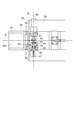
図1〜図3に示すように、陽子線治療装置100は、患者(被照射体)51の体内の腫瘍(照射目標物)Pに対して陽子線(荷電粒子線)を照射する装置である。
As shown in FIGS. 1 to 3, the proton
この陽子線治療装置100は、回転ガントリ103(照射室)に取り付けられて治療台(載置台)105の回りに回転可能とされた陽子線照射部(荷電粒子線照射部)1を備えている。
The proton
この陽子線照射部1は、図3に示すように、陽子線の照射方向Aに順に配列され、陽子線ビームを順に通過させてビームを整形する散乱体5、リッジフィルタ部7、ファインディグレーダ9、ブロックコリメータ11、ボーラス13、マルチリーフコリメータ15、装置各部の駆動を制御する照射制御部17を備えている。
As shown in FIG. 3, the proton
この陽子線照射部1には、陽子線発生部として機能するサイクロトロン3で発生した陽子線が輸送装置を通じて送り込まれる。そして、送り込まれた細い陽子線を、例えば厚さ数mmの鉛からなる散乱体(ビーム拡大部)5を通過させることによって、照射方向Aに直交する方向に広がりを持たせて、幅広いビームに拡大する。
A proton beam generated by a
上記散乱体5からの陽子線ビームは、患者51体内の腫瘍Pの厚み(照射方向Aの長さ)に対応して陽子線のエネルギー深さに分布を持たせるためのリッジフィルタ部(ピーク調整フィルタ部)7に入射される。このリッジフィルタ部7は、階段状に厚みの変化する金属棒が簾状に並べられてなるフィルタ7aを複数有しており、それら複数のフィルタ7aは、金属棒の形状の相違により互いに異なる陽子線の拡大ブラッグピーク(以下「SOBP」という)を形成させる。そして、リッジフィルタ部7は、照射制御部17の制御により駆動され、上記複数のフィルタ7aの中から適宜選択されたフィルタを陽子線の通過位置に挿入する機構を有している。この構成により、リッジフィルタ部7は、陽子線を通過させるフィルタ7aを選択的に変更可能であり、陽子線のSOBPのピークの幅及び位置を調整することができる。
The proton beam from the scatterer 5 has a ridge filter portion (peak adjustment) for distributing the proton beam energy depth corresponding to the thickness of the tumor P in the patient 51 (length in the irradiation direction A). The light is incident on the
このリッジフィルタ部7を通過した陽子線は、治療対象である患者体内51の腫瘍Pの深さに応じてビームのエネルギーを調整し、最大到達深さを調整するためのファインディグレーダ(ビームエネルギー調整部)9に入射される。このファインディグレーダ9は、例えば2個の楔型をした対向するアクリルブロック9a、9bから構成され、照射制御部17の制御により上記ブロック9a、9bの重なり方を調節することによって、陽子線が通過する部分の厚みを連続的に変化させることができる。陽子線は、通過した物質の厚みに応じてエネルギーを失い、患者51体内において到達する深さが変わるので、このファインディグレーダ9の調節により、陽子線のSOBPの位置を、患者51体内における腫瘍Pの深さ方向(照射方向A)の位置に合わせることができる。
The proton beam that has passed through the
このファインディグレーダ9を通過した陽子線ビームは、陽子線の平面形状(照射方向Aから見た形状)を粗く整形するためのブロックコリメータ11に入射される。後述するマルチリーフコリメータ15に加えて、ここで、ブロックコリメータ11による整形を行っているのは、患者の近くでブロックコリメータ11による2次放射線が発生しないようにするためである。
The proton beam that has passed through the fine degrader 9 is incident on a
このブロックコリメータ11を通過した陽子線は、例えば樹脂製の不整形フィルタであるボーラス(補償フィルタ)13に入力され、腫瘍Pの最大深さの断面形状と組織の不均一性に関する補正が行われる。このボーラス13の形状は、腫瘍の輪郭線と、例えばX線CTのデータから求められる周辺組織の電子密度とに基づいて、算出される。このようなボーラス13を用いることにより、陽子線ビームの最遠部(最大到達深さの部分)の立体形状が、腫瘍Pの最大深さ部分の形状に合わせて整形されるので腫瘍Pに対する線量集中性を更に高めることができる。
The proton beam that has passed through the
このボーラス13を通過した陽子線ビームは、マルチリーフコリメータ(形状可変コリメータ)15に入射される。マルチリーフコリメータ15は、真鍮製で幅数mmの多数の櫛歯をもつ2つの遮線部15a,15bが、上記櫛歯の先端を中心で突き合わせるように配列されて構成されている。そして、照射制御部17の制御により、遮線部15a,15bが、多数の上記櫛歯のそれぞれを長手方向に進退させることで、マルチリーフコリメータ15は、陽子線ビームが通過する開口15cの位置及び形状を変化させることができる。
The proton beam passing through the
マルチリーフコリメータ15を通過した陽子線ビームは、上記開口15cの形状に対応する輪郭に切り取られるので、マルチリーフコリメータ15は、開口15cの形状を変化させることで、入射する陽子線ビームの所望の平面位置及び平面形状を切り出すことができる。このように所望の平面位置において所望の平面形状に切り出された陽子線ビームは、治療用陽子線として患者51に照射される。そして、マルチコリメータ15の開口15cの平面位置及び平面形状を変化させて照射野の位置を順次水平方向(照射方向Aに直交する方向)に移動しながら照射を繰り返すことで、腫瘍P全体に陽子線ビームを照射する。
The proton beam beam that has passed through the
更に、この1陽子線照射部1は、照射野に照射された照射線量をモニタする手段として、線量モニタ23を備えている。線量モニタ23は、ファインディグレーダ9とブロックコリメータ11との間に設けられ、通過する陽子線の線量を検知する。線量モニタ23は、検知した線量をモニタ信号s1として照射制御部17に送信し、照射制御部17はモニタ信号s1に基づいて照射野に照射された照射線量を認識することができる。
Furthermore, this 1 proton
また、陽子線治療装置100には、患者51のX線透視画像取得するX線撮影装置(X線透視画像取得手段)が設けられている。このX線撮影装置は、X線発生器、患者51を透過したX線を検出するX線検出器を備えている。これらのX線発生器及びX線検出器は、回転ガントリ103に固定され、患者51回りに回転可能とされている。本実施形態では、二つのX線発生器を備え、これらのX線発生装置は、90度異なる位置に配置されている。また、X線発生器に対向する位置に、X線検出器が配置されている。X線撮影装置は、X線検出器によって検出されたデータに基づいて、患者51のX線透視画像を作成し、骨、金属マーカーを検出して患者51の位置を測定することができる。
In addition, the
ここで、陽子線治療装置100は、回転ガントリ103に取り付けられて治療台105の回りに回転可能とされた一対のPETカメラ(第1の検出器、第2の検出器)30を有するPET装置31を備えている。すなわち、PETカメラ30は、回転ガントリ103に取付けられた陽子線照射部1と一体としてX軸回りに回転可能とされている。PET装置31は、PETカメラ30の他に、図示していない画像処理部、記録部、表示部等を備えている。画像処理部は、PETカメラ30によって取得された画像情報に基づいて画像処理を行いPET画像を生成する。記録部は、生成されたPET画像等を記録する。生成されたPET画像は、表示部により表示される。
Here, the
このPETカメラ30は、治療台105上の患者51の両側に配置され、消滅γ線を検出するものである。具体的には、患者51には腫瘍Pに集積する放射性薬剤(例えば、11Cメチオニン)が投与(注入)され、PETカメラ30は、腫瘍P(放射性薬剤の到達位置)から発生する消滅γ線を検出する。PET装置31は、PETカメラ30による消滅γ線の検出結果に基づいて腫瘍Pの位置を検出する照射目標位置検出手段として機能するものである。
The
また、PETカメラ30は、患者51に照射された陽子線の入射陽子核と腫瘍P内の原子核との核反応によって生成されたポジトロン放出核からの消滅γ線を検出することができる。更に、PET装置31は、PETカメラ30による消滅γ線の検出結果に基づいて実際に照射された陽子線の患者51の体内における到達位置を検出する陽子線(荷電粒子線)到達位置検出手段として機能するものである。すなわち、PET装置31は、治療で用いる陽子線の入射陽子核と患者51の体内中の原子核との相互核反応により体内中で生成されるポジトロン放出核種から消滅γ線を計測し生成核種ごとの強度分布を測定することで、患者51体内における実際の陽子線到達位置を検出することができる。
Further, the
PETカメラ30は、図4に示すように、回転ガントリ103の回転中心軸X(以下、「X軸」という。)方向に移動可能とされると共に、X軸と直交するY軸方向に移動可能とされている。一対のPETカメラ30を各々支持するPETカメラ支持部32は、X軸方向に延在する支持部材33と、この支持部材33に沿ってX軸方向に移動するX軸方向移動部材34と、このX軸方向移動部材34の先端部34aに設けられY軸方向に延在するY軸方向延在部材35と、このY軸方向延在部材35に沿ってY軸方向に移動するY軸方向移動部材36とを有している。そして、PETカメラ30は、Y軸方向移動部材36に固定され、その検出面30aが互いに対向するように配置されている。
As shown in FIG. 4, the
支持部材33には、Y軸方向における外方に張り出す張出部33aが形成され、この張出部33aが回転ガントリ103のフレーム103a(図2参照)に固定されている。また、支持部材33は、回転ガントリ103の背面パネル103bの背面側(図示右側)に配置されている。支持部材33及びX軸方向移動部材34には、X軸方向移動部材34が移動する方向を案内するスライドガイド38が形成され、X軸方向移動部材34は、スライドガイド38を介してX軸方向に移動可能に支持されている。そして、X軸方向移動部材34は、支持部材33に固定されたエアシリンダ37によって駆動され、X軸方向に往復動可能とされている。
The
Y軸方向延在部材35及びY軸方向移動部材36には、図5に示すように、Y軸方向移動部材36が移動する方向を案内するスライドガイド39が設置され、Y軸方向移動部材36は、スライドガイド39を介してY軸方向に移動可能に支持されている。そして、Y軸方向移動部材36は、Y軸方向延在部材35に固定されたモータ40によって駆動され、Y軸方向に往復動可能とされている。
As shown in FIG. 5, the Y-axis
モータ40は、その出力軸41がX軸及びY軸に直交するZ軸方向(図5における上下方向)に延在するように配置されている。出力軸41は、カップリング42を介して、Z軸方向に延在する駆動軸43に接続されている。駆動軸43は、一対の軸受け44によってY軸方向延在部材35に回転可能に支持されている。駆動軸43の一対の軸受け44間には、ギア45が設けられている。また、駆動軸43のカップリング42と反対側の端部には、ブレーキ46及び、ポテンションメータ47が設置されている。
The
また、Y軸方向移動部材36には、ギア45と噛み合うラック48がY軸方向に形成されている。そして、モータ40を回転駆動することで、ギア45及びラック48によって駆動力が伝達され、Y軸方向移動部材36がY軸方向に往復動する。これにより、PETカメラ30を患者51に対して接近させることができる。患者に接近させてPETカメラ30を配置することで、消滅γ線の検出精度が向上される。
A
このPETカメラ30は、回転ガントリ103の背面パネル103bより背面側に収納可能とされ、計測時には、エアシリンダ37によって駆動されて、患者51の両側に配置される。
The
また、陽子線治療装置100は、治療台105の位置調整を行う治療台位置制御部(載置台制御部)を有している。そして、この治療台位置制御部は、PET装置31によって取得されたPET画像、X線撮影装置によって取得されたX線透視画像に基づいて、治療台105の位置を制御するものであり、治療台105上の患者51の腫瘍Pに陽子線が照射されるように、治療台105の位置を調整する。
In addition, the
照射制御部17は、患者51の腫瘍Pの立体形状に基づいて作成された腫瘍マップ(目標物マップ)19に格納された情報を参照しながら、特に、リッジフィルタ部7、ファインディグレーダ9、及びマルチリーフコリメータ15の動作を制御するものである。また、ここでは、照射野の最遠部の形状が、腫瘍の最大深さ部分の複雑な形状に対応して整形されるように、予め準備されたボーラス13が、所定の位置にセットされている。
The
さらに、照射制御部17は、PET装置によって検出された陽子線の到達位置に応じて、陽子線のビーム調整を行う。すなわち、照射制御部17は、患者51体内における陽子線の実際の到達位置と腫瘍Pの位置とが一致するように、リッジフィルタ部7、ファインディグレーダ9、及びマルチリーフコリメータ15の動作を制御して陽子線のビームを調整する。
Further, the
次に、このように構成された陽子線治療装置100を用いた陽子線照射方法(荷電粒子線照射方法)について説明する。
Next, a proton beam irradiation method (charged particle beam irradiation method) using the thus configured proton
陽子線治療装置100を使用していないときには、PETカメラ30は、背面パネル103bの背面側に収納され状態となっている。ここでは、一例として、脳腫瘍の患者に対する陽子線治療について説明する。まず、回転ガントリ103内の治療台105上に患者51を寝かせる。患者51の長手方向が、X軸方向に沿うように配置されている。次に、患者51に11Cメチオニンを投与し(S1)、脳腫瘍に11Cメチオニンが集積するのを待つ(S2)。続いて、脳腫瘍に集積した11Cメチオニンから放出される消滅γ線をPETカメラ30によって測定する(第1の検出工程、S3)。このとき、エアシリンダ37を駆動して、PETカメラ30をX軸方向に移動させて患者51の両側に配置し、モータ40を駆動してPETカメラ30をY軸方向に移動させて、PETカメラ30同士の間隔を調節する。3次元画像測定を行う場合には、回転ガントリ103を回転させて、消滅γ線の計測を行う。
When the proton
次に、PETカメラ30による測定結果に基づいて、PET画像を作成して脳腫瘍の位置を検出する(照射目標位置検出工程、S4)。続いて、X線撮影装置によって透視撮影を行い患者51のX線画像を作成して(X線透視画像取得工程)、骨及び金属マーカーの位置を確認する。なお、PET撮影及びX線撮影の順序を入れ替えてもよく、交互に複数回撮影を行っても良い。また、必要に応じて、回転ガントリ103を回転させて、X線発生器、X線検出器の位置を変える。
Next, based on the measurement result by the
次に、PET画像とX線画像に基づいて、照射計画を立案する(S6)。ここでは、照射計画として、例えば、絶対線量、線量分布、患者51の位置等を決定する。続いて、決定された照射計画に基づいて、治療台105の位置調整を行い(載置台位置調整工程、S7)、患者51を適切な位置に配置する。
Next, an irradiation plan is made based on the PET image and the X-ray image (S6). Here, as the irradiation plan, for example, the absolute dose, the dose distribution, the position of the
次に、決定された照射計画に従ってビーム調整を行い、必要に応じて回転ガントリ103を回転させて、陽子線照射部1の位置を変更し、腫瘍に向けて陽子線を1回照射する(S8)。そして、照射された陽子線と患者51体内の原子核との核反応によって生成されたポジトロン放出核からの消滅γ線をPETカメラ30で測定する(第2の検出工程、S9)。このとき、PETカメラ30同士が互いに接近するようにY軸方向に移動させ、PETカメラ30を患者51に近づけて、消滅γ線の検出を行う。また、PETカメラ30を回転させて測定を行ってもよい。続いて、PETカメラ30による測定結果に基づいて、PET画像を作成し患者51の体内における陽子線の到達位置を検出し、実際の照射野を確認する(荷電粒子線到達位置検出工程、S10)。
Next, beam adjustment is performed according to the determined irradiation plan, the
次に、実際に照射された陽子線の患者51体内における到達位置と、照射計画による照射目標位置(腫瘍の位置)とを比較し、位置ずれがある場合には、陽子線が照射目標位置の許容範囲内に照射されるようにビームの調整を行う(ビーム調整工程、S11)。ビーム調整終了後、陽子線を照射する(S12)。なお、再度、S8〜S11を実施してよい。
Next, the arrival position of the actually irradiated proton beam in the
このような陽子線治療装置100によれば、回転ガントリ103にPETカメラ30が設けられ、このPETカメラ30によって、照射された陽子線の入射陽子核と腫瘍内の原子核との核反応により生成されるポジトロン放出核からの消滅γ線を計測することができるので、実際に照射された陽子線の到達位置を確認することができる。すなわち、治療中に陽子線を照射しながら陽子線の到達位置を検出することができる。また、回転ガントリ103にPETカメラ30が固定されているので、回転ガントリ103の回転に合わせて、PETカメラ30を患者51回りに回転させることができ、陽子線を照射した直後に消滅γ線の測定を行うことができる。また、PETカメラ30の移動の自由度が向上されると共に、小型化されたPETカメラ30を用いて3次元測定を行うことができ、PETカメラ30用の別の回転駆動部を設ける必要もない。また、PETカメラ30が陽子線照射部1に同期して回転するので、PETカメラ30と陽子線照射部1との回転方向における位置関係を維持しながら、消滅γ線の検出を行うことが可能とされている。
According to such a proton
また、PETカメラ30は、X軸方向に移動可能であると共に、回転ガントリ103の背面パネル103bの背面側に収納可能とされている。このようにPETカメラ30をX軸方向に移動させることで、PETカメラ30による検出範囲の拡大することができる。また、PETカメラ30を適宜移動させることで、PETカメラ30が陽子線照射部1の回転の妨げになることがない。さらに、患者51の回転ガントリ103内への搬入、搬出の際にPETカメラ30が邪魔にならない。また、被照射体の大きさに合わせて、PETカメラ30を移動させることもできるので、所望の部位の照射位置の確認が容易になる。
The
また、PETカメラ30が患者51を挟み込む方向(Y軸方向)に移動可能であり、PETカメラ30間の距離を任意に変えることが可能とされているので、PETカメラ30をY軸方向に患者51に接近させることで、消滅γ線の検出精度を向上させることができる。
Further, since the
また、従来、例えば脳腫瘍の放射線治療では、患者の位置決めを高精度で実現すべく、患者の頭部を、固定具を用いて固定していたため、患者にとって大きな負担となっていた。本発明による陽子線照射装置及び陽子線照射方法では、照射室内において、患者51を治療台105に寝かせた状態でPETカメラ30を用いて腫瘍の位置確認を行うことができ、腫瘍位置と実際に照射された陽子線の到達位置との位置ずれを修正し、適切な位置に患者51を位置決めすることができる。これにより、患者の位置決めを高い精度で行うことができるため、患者の固定の簡素化が図られ、患者への負担を軽減することができる。
Conventionally, for example, in the case of radiation therapy for brain tumors, the patient's head has been fixed using a fixing tool in order to realize the positioning of the patient with high accuracy, which has been a heavy burden on the patient. In the proton beam irradiation apparatus and the proton beam irradiation method according to the present invention, the position of the tumor can be confirmed using the
次に、本発明の第2実施形態に係る陽子線治療装置について、図7及び図8を参照しながら説明する。この第2実施形態の陽子線治療装置が第1実施形態の陽子線治療装置100と違う点は、第2実施形態のPETカメラ60は更にY軸回りに回転可能である点、及びPETカメラ60の検出面60aの形状が異なる点である。
Next, a proton beam therapy apparatus according to the second embodiment of the present invention will be described with reference to FIGS. The proton beam treatment apparatus according to the second embodiment is different from the proton
PETカメラ60を支持するPETカメラ支持部61は、Y軸方向移動部材36の内側の端部36aにPETカメラ60を固定するカメラ固定部62を備えている。このカメラ固定部62には、PETカメラ60を回転駆動するモータ63が取り付けられている。このモータ63は、その出力軸64がY軸方向に沿って配置されている。そして、モータ63の出力軸64にPETカメラ60が接続されY軸回りに回転可能とされている。
The PET
PETカメラ60の検出面60aは、円弧状に湾曲し、一対の検出面60aは互いに対向して配置されている。PETカメラ60は、収納時、及びX軸方向への移動の際には、その長手方向がX軸方向に沿うように配置される(図9に示す状態)。また、γ線の計測時には、PETカメラ60は、円弧の中心軸がX軸方向と平行になる様に配置される。なお、X軸方向と平行にならない位置でPETカメラ60の回転を停止させ、様々な角度からの測定も可能である。
The
このように構成しても第1実施形態の陽子線治療装置100と同様の効果を得ることができ、加えて、PETカメラ60がY軸回りに回転可能であるため、PETカメラ60の移動の自由度が一層向上され、様々な方向から照射位置の測定を行うことができ、測定精度の向上が図られている。
Even if comprised in this way, the effect similar to the proton
本発明は、上記実施形態に限定されるものではない。上記実施形態では、PETカメラがX軸回りに回転可能な構成とされているが、X軸回りに回転しない構成でもよく、その他の方向に回転可能な構成としてもよい。また、PETカメラが互いに接近する方向に移動可能な構成とされているが、PETカメラは互いに接近する方向に移動しない構成としてもよい。また、エアシリンダ、モータを用いて、PETカメラを移動させているが、油圧シリンダ等その他の駆動装置を用いてPETカメラを移動させてもよい。また、PETカメラのX軸方向の移動、Y軸方向の移動は、直線状に移動しなくてもよく、曲線状、円弧状に移動してもよい。 The present invention is not limited to the above embodiment. In the above embodiment, the PET camera is configured to be rotatable about the X axis, but may be configured not to rotate about the X axis, or may be configured to be rotatable in other directions. Further, although the PET cameras are configured to be movable in a direction approaching each other, the PET cameras may be configured not to move in a direction approaching each other. Moreover, although the PET camera is moved using an air cylinder and a motor, the PET camera may be moved using another driving device such as a hydraulic cylinder. Further, the movement in the X-axis direction and the movement in the Y-axis direction of the PET camera may not be moved linearly, but may be moved in a curved shape or an arc shape.
また、上記実施形態では、PETカメラは、回転ガントリに取り付けられ、陽子線照射部と一体としてX軸回りに回転可能とされているが、PETカメラは回転ガントリ及び陽子線照射部と一体として回転しなくてもよい。例えば、PETカメラを回転駆動させるための駆動装置を別に設けて、回転ガントリ及び陽子線照射部の回転に追従するようにPETカメラを回転させてもよく、回転ガントリ及び陽子線照射部の回転と無関係にPETカメラを回転させてもよい。 In the above embodiment, the PET camera is attached to the rotating gantry and is rotatable around the X axis integrally with the proton beam irradiation unit. However, the PET camera is rotated integrally with the rotating gantry and the proton beam irradiation unit. You don't have to. For example, a separate driving device for rotationally driving the PET camera may be provided, and the PET camera may be rotated so as to follow the rotation of the rotating gantry and the proton beam irradiation unit. The PET camera may be rotated regardless.
また、上記実施形態では、X線装置を備え、X線撮影を実施しているが、X線撮影を省略してもよい。また、上記実施形態では、放射性薬剤をメチオニンとしているが、照射目標物に応じて、その他の放射性薬剤を適用してもよい。また、上記実施形態では、脳腫瘍について、説明しているが、その他の腫瘍に対して適用してもよい。 In the above embodiment, an X-ray apparatus is provided and X-ray imaging is performed. However, X-ray imaging may be omitted. In the above embodiment, the radiopharmaceutical is methionine, but other radiopharmaceuticals may be applied depending on the irradiation target. Moreover, although the said embodiment demonstrated the brain tumor, you may apply with respect to another tumor.
また、上記実施形態では、陽子線を照射する陽子線照射装置に本発明を適用しているが、本発明は、炭素線照射装置等の他の荷電粒子線照射装置にも適用が可能である。 Moreover, in the said embodiment, although this invention is applied to the proton beam irradiation apparatus which irradiates a proton beam, this invention is applicable also to other charged particle beam irradiation apparatuses, such as a carbon beam irradiation apparatus. .
また、上記実施形態では、第1の検出器及び第2の検出器を同一のPETカメラとしているが、別々のPETカメラを備える構成としても良い。 Moreover, in the said embodiment, although the 1st detector and the 2nd detector are made into the same PET camera, it is good also as a structure provided with a separate PET camera.
1…陽子線照射部(荷電粒子線照射部)、17…照射制御部、30…PETカメラ(第1の検出器、第2の検出器)、51…患者(被照射体)、100…陽子線治療装置、103…回転ガントリ(照射室)、105…治療台(載置台)、P…腫瘍(照射目標物)、X…X軸方向、Y…Y軸方向。
DESCRIPTION OF
Claims (4)
前記被照射体に注入された放射性薬剤が到達した位置である照射目標位置から発生する消滅γ線を検出する第1の検出器と、
前記第1の検出器による消滅γ線の検出結果に基づいて照射目標位置を検出する照射目標位置検出手段と、
前記回転ガントリに取り付けられて前記載置台回りに回転可能とされると共に、前記被照射体に照射された荷電粒子線と前記被照射体内の原子核との核反応によって生成されたポジトロン放出核からの消滅γ線を検出する第2の検出器と、
前記第2の検出器による消滅γ線の検出結果に基づいて荷電粒子線到達位置を検出する荷電粒子線到達位置検出手段と、
前記荷電粒子線到達位置検出手段によって検出された荷電粒子線到達位置と、前記目標位置検出手段によって検出された照射目標位置とが一致するように、荷電粒子線のビームを調整する照射制御部と、
を備えることを特徴とする荷電粒子線照射装置。 In a charged particle beam irradiation apparatus in which a mounting table on which an object to be irradiated is placed is arranged at a predetermined position in an irradiation chamber constituted by a rotating gantry , and the charged particle beam is irradiated to the object to be irradiated.
A first detector for detecting annihilation γ-rays generated from an irradiation target position, which is a position where a radiopharmaceutical injected into the irradiated body has reached;
Irradiation target position detection means for detecting the irradiation target position based on the detection result of the annihilation γ-ray by the first detector;
The gantry is attached to the rotating gantry and can be rotated around the mounting table, and from a positron emitting nucleus generated by a nuclear reaction between a charged particle beam irradiated on the irradiated object and a nucleus in the irradiated object. A second detector for detecting annihilation gamma rays;
Charged particle beam arrival position detection means for detecting a charged particle beam arrival position based on the detection result of annihilation γ rays by the second detector;
An irradiation control unit that adjusts the charged particle beam so that the charged particle beam arrival position detected by the charged particle beam arrival position detection unit matches the irradiation target position detected by the target position detection unit; ,
A charged particle beam irradiation apparatus comprising:
The charged particle beam irradiation apparatus according to claim 1, wherein the irradiation chamber includes a charged particle beam irradiation unit that is rotatable around the irradiated object.
Priority Applications (1)
| Application Number | Priority Date | Filing Date | Title |
|---|---|---|---|
| JP2007009544A JP4984906B2 (en) | 2007-01-18 | 2007-01-18 | Charged particle beam irradiation equipment |
Applications Claiming Priority (1)
| Application Number | Priority Date | Filing Date | Title |
|---|---|---|---|
| JP2007009544A JP4984906B2 (en) | 2007-01-18 | 2007-01-18 | Charged particle beam irradiation equipment |
Related Child Applications (3)
| Application Number | Title | Priority Date | Filing Date |
|---|---|---|---|
| JP2011103181A Division JP5317227B2 (en) | 2011-05-02 | 2011-05-02 | Charged particle beam irradiation equipment |
| JP2011223669A Division JP5481711B2 (en) | 2011-10-11 | 2011-10-11 | Charged particle beam irradiation equipment |
| JP2011223670A Division JP5504398B2 (en) | 2011-10-11 | 2011-10-11 | Charged particle beam irradiation equipment |
Publications (2)
| Publication Number | Publication Date |
|---|---|
| JP2008173299A JP2008173299A (en) | 2008-07-31 |
| JP4984906B2 true JP4984906B2 (en) | 2012-07-25 |
Family
ID=39700799
Family Applications (1)
| Application Number | Title | Priority Date | Filing Date |
|---|---|---|---|
| JP2007009544A Expired - Fee Related JP4984906B2 (en) | 2007-01-18 | 2007-01-18 | Charged particle beam irradiation equipment |
Country Status (1)
| Country | Link |
|---|---|
| JP (1) | JP4984906B2 (en) |
Families Citing this family (21)
| Publication number | Priority date | Publication date | Assignee | Title |
|---|---|---|---|---|
| US8017915B2 (en) | 2008-03-14 | 2011-09-13 | Reflexion Medical, Inc. | Method and apparatus for emission guided radiation therapy |
| JP5104951B2 (en) * | 2008-08-08 | 2012-12-19 | 株式会社島津製作所 | Particle beam therapy system |
| JP5130175B2 (en) * | 2008-09-29 | 2013-01-30 | 株式会社日立製作所 | Particle beam irradiation system and control method thereof |
| US8497480B2 (en) * | 2008-12-16 | 2013-07-30 | Shimadzu Corporation | Particle radiotherapy apparatus |
| US20120165651A1 (en) * | 2009-03-23 | 2012-06-28 | National Institute Of Radiological Sciences | Detector rotation type radiation therapy and imaging hybrid device |
| WO2010109586A1 (en) | 2009-03-23 | 2010-09-30 | 独立行政法人放射線医学総合研究所 | Concealment-type radiotherapy/imaging combined device |
| WO2010110255A1 (en) * | 2009-03-24 | 2010-09-30 | 国立大学法人北海道大学 | Radiation therapy apparatus |
| JP5349145B2 (en) * | 2009-06-05 | 2013-11-20 | 株式会社東芝 | Particle beam therapy system |
| JP5472731B2 (en) | 2010-03-02 | 2014-04-16 | 大学共同利用機関法人 高エネルギー加速器研究機構 | Muon monitoring system in charged particle beam medicine |
| US9220921B2 (en) * | 2010-09-01 | 2015-12-29 | Empire Technology Development Llc | Method and system for radioisotope ion beam gamma therapy |
| CN103650095B (en) | 2011-03-31 | 2016-12-07 | 反射医疗公司 | For the system and method used in launching the radiotherapy guided |
| JP2013013613A (en) * | 2011-07-05 | 2013-01-24 | Sumitomo Heavy Ind Ltd | Charged particle beam irradiation device |
| CN104939847A (en) * | 2014-03-25 | 2015-09-30 | 北京亿仁赛博医疗科技研发中心有限公司 | Linear accelerator |
| CN107924730B (en) | 2015-06-10 | 2021-09-28 | 反射医疗公司 | High bandwidth binary multileaf collimator design |
| US10695586B2 (en) | 2016-11-15 | 2020-06-30 | Reflexion Medical, Inc. | System for emission-guided high-energy photon delivery |
| WO2018093849A1 (en) | 2016-11-15 | 2018-05-24 | Reflexion Medical, Inc. | Methods for radiation delivery in emission-guided radiotherapy |
| CN116943051A (en) | 2016-11-15 | 2023-10-27 | 反射医疗公司 | Radiotherapy patient platform |
| WO2018183748A1 (en) | 2017-03-30 | 2018-10-04 | Reflexion Medical, Inc. | Radiation therapy systems and methods with tumor tracking |
| CN114699655A (en) | 2017-07-11 | 2022-07-05 | 反射医疗公司 | Method for persistence management of PET detectors |
| JP7315961B2 (en) | 2017-08-09 | 2023-07-27 | リフレクション メディカル, インコーポレイテッド | Systems and methods for anomaly detection in guided emission radiation therapy |
| US11369806B2 (en) | 2017-11-14 | 2022-06-28 | Reflexion Medical, Inc. | Systems and methods for patient monitoring for radiotherapy |
Family Cites Families (3)
| Publication number | Priority date | Publication date | Assignee | Title |
|---|---|---|---|---|
| JP4514907B2 (en) * | 2000-07-06 | 2010-07-28 | 浜松ホトニクス株式会社 | Diagnosis and treatment equipment |
| WO2002063638A1 (en) * | 2001-02-06 | 2002-08-15 | Gesellschaft für Schwerionenforschung mbH | Gantry system for transport and delivery of a high energy ion beam in a heavy ion cancer therapy facility |
| JP2006021046A (en) * | 2005-07-05 | 2006-01-26 | Mitsubishi Heavy Ind Ltd | Radiotherapy apparatus |
-
2007
- 2007-01-18 JP JP2007009544A patent/JP4984906B2/en not_active Expired - Fee Related
Also Published As
| Publication number | Publication date |
|---|---|
| JP2008173299A (en) | 2008-07-31 |
Similar Documents
| Publication | Publication Date | Title |
|---|---|---|
| JP4984906B2 (en) | Charged particle beam irradiation equipment | |
| JP4797140B2 (en) | Charged particle beam irradiation equipment | |
| US10328285B2 (en) | Hadron radiation installation and verification method | |
| JP6844942B2 (en) | Particle beam therapy system and management system for particle beam therapy | |
| US9061143B2 (en) | Charged particle beam irradiation system and charged particle beam irradiation planning method | |
| EP1871477B1 (en) | System for taking wide-field beam-eye-view (bev) x-ray-images simultaneously to the proton therapy delivery | |
| WO2013146945A1 (en) | Device for remotely cross-firing particle beams | |
| EP3251600B1 (en) | Radiographic imaging apparatus and particle beam therapy system | |
| EP2623155A1 (en) | Radiation therapy device control device and radiation therapy device control method | |
| WO2011061827A1 (en) | Radiation therapy apparatus control method and radiation therapy apparatus control device | |
| JP2013046709A (en) | Displacement measurement method of isocenter in radiotherapy apparatus, adjustment method of displacement of the same, and phantom for displacement measurement | |
| WO2013127005A1 (en) | Reduced dose x-ray imaging | |
| US20080279339A1 (en) | Stand For Holding a Radiation Detector For a Radiation Therapy Device | |
| JP5317227B2 (en) | Charged particle beam irradiation equipment | |
| JP5504398B2 (en) | Charged particle beam irradiation equipment | |
| JP5481711B2 (en) | Charged particle beam irradiation equipment | |
| US8403821B2 (en) | Radiotherapy apparatus controller and radiation irradiating method | |
| JP6719621B2 (en) | Particle therapy system and management system for particle therapy | |
| JP2013013613A (en) | Charged particle beam irradiation device | |
| KR101474926B1 (en) | X-ray imaging apparatus |
Legal Events
| Date | Code | Title | Description |
|---|---|---|---|
| A621 | Written request for application examination |
Free format text: JAPANESE INTERMEDIATE CODE: A621 Effective date: 20090716 |
|
| A711 | Notification of change in applicant |
Free format text: JAPANESE INTERMEDIATE CODE: A712 Effective date: 20100507 |
|
| A977 | Report on retrieval |
Free format text: JAPANESE INTERMEDIATE CODE: A971007 Effective date: 20110113 |
|
| A131 | Notification of reasons for refusal |
Free format text: JAPANESE INTERMEDIATE CODE: A131 Effective date: 20110301 |
|
| RD03 | Notification of appointment of power of attorney |
Free format text: JAPANESE INTERMEDIATE CODE: A7423 Effective date: 20110311 |
|
| A521 | Request for written amendment filed |
Free format text: JAPANESE INTERMEDIATE CODE: A523 Effective date: 20110502 |
|
| A02 | Decision of refusal |
Free format text: JAPANESE INTERMEDIATE CODE: A02 Effective date: 20110712 |
|
| A521 | Request for written amendment filed |
Free format text: JAPANESE INTERMEDIATE CODE: A523 Effective date: 20111011 |
|
| A521 | Request for written amendment filed |
Free format text: JAPANESE INTERMEDIATE CODE: A523 Effective date: 20111020 |
|
| A521 | Request for written amendment filed |
Free format text: JAPANESE INTERMEDIATE CODE: A523 Effective date: 20111020 |
|
| A911 | Transfer to examiner for re-examination before appeal (zenchi) |
Free format text: JAPANESE INTERMEDIATE CODE: A911 Effective date: 20111122 |
|
| TRDD | Decision of grant or rejection written | ||
| A01 | Written decision to grant a patent or to grant a registration (utility model) |
Free format text: JAPANESE INTERMEDIATE CODE: A01 Effective date: 20120131 |
|
| R155 | Notification before disposition of declining of application |
Free format text: JAPANESE INTERMEDIATE CODE: R155 |
|
| A521 | Request for written amendment filed |
Free format text: JAPANESE INTERMEDIATE CODE: A523 Effective date: 20120416 |
|
| A61 | First payment of annual fees (during grant procedure) |
Free format text: JAPANESE INTERMEDIATE CODE: A61 Effective date: 20120416 |
|
| R150 | Certificate of patent or registration of utility model |
Ref document number: 4984906 Country of ref document: JP Free format text: JAPANESE INTERMEDIATE CODE: R150 Free format text: JAPANESE INTERMEDIATE CODE: R150 |
|
| FPAY | Renewal fee payment (event date is renewal date of database) |
Free format text: PAYMENT UNTIL: 20150511 Year of fee payment: 3 |
|
| S533 | Written request for registration of change of name |
Free format text: JAPANESE INTERMEDIATE CODE: R313533 |
|
| R350 | Written notification of registration of transfer |
Free format text: JAPANESE INTERMEDIATE CODE: R350 |
|
| R250 | Receipt of annual fees |
Free format text: JAPANESE INTERMEDIATE CODE: R250 |
|
| R250 | Receipt of annual fees |
Free format text: JAPANESE INTERMEDIATE CODE: R250 |
|
| R250 | Receipt of annual fees |
Free format text: JAPANESE INTERMEDIATE CODE: R250 |
|
| R250 | Receipt of annual fees |
Free format text: JAPANESE INTERMEDIATE CODE: R250 |
|
| R250 | Receipt of annual fees |
Free format text: JAPANESE INTERMEDIATE CODE: R250 |
|
| R250 | Receipt of annual fees |
Free format text: JAPANESE INTERMEDIATE CODE: R250 |
|
| R250 | Receipt of annual fees |
Free format text: JAPANESE INTERMEDIATE CODE: R250 |
|
| LAPS | Cancellation because of no payment of annual fees |