CN110863417A - A fast-installed steel-concrete composite girder bridge and its construction method - Google Patents
A fast-installed steel-concrete composite girder bridge and its construction method Download PDFInfo
- Publication number
- CN110863417A CN110863417A CN201911033359.8A CN201911033359A CN110863417A CN 110863417 A CN110863417 A CN 110863417A CN 201911033359 A CN201911033359 A CN 201911033359A CN 110863417 A CN110863417 A CN 110863417A
- Authority
- CN
- China
- Prior art keywords
- steel
- concrete
- bridge
- beams
- longitudinal
- Prior art date
- Legal status (The legal status is an assumption and is not a legal conclusion. Google has not performed a legal analysis and makes no representation as to the accuracy of the status listed.)
- Pending
Links
- 239000004567 concrete Substances 0.000 title claims abstract description 133
- 239000002131 composite material Substances 0.000 title claims abstract description 69
- 238000010276 construction Methods 0.000 title claims abstract description 32
- 229910000831 Steel Inorganic materials 0.000 claims abstract description 89
- 239000010959 steel Substances 0.000 claims abstract description 89
- 239000004574 high-performance concrete Substances 0.000 claims abstract description 19
- 238000003466 welding Methods 0.000 claims abstract description 5
- 230000000149 penetrating effect Effects 0.000 claims description 12
- 238000012545 processing Methods 0.000 claims description 6
- 230000002787 reinforcement Effects 0.000 claims description 6
- 229910001294 Reinforcing steel Inorganic materials 0.000 claims 7
- 238000004519 manufacturing process Methods 0.000 abstract 1
- 238000010586 diagram Methods 0.000 description 7
- 238000005452 bending Methods 0.000 description 4
- 238000009434 installation Methods 0.000 description 3
- 238000000034 method Methods 0.000 description 3
- 238000009417 prefabrication Methods 0.000 description 3
- 238000011065 in-situ storage Methods 0.000 description 2
- 230000002411 adverse Effects 0.000 description 1
- 230000009286 beneficial effect Effects 0.000 description 1
- 230000006835 compression Effects 0.000 description 1
- 238000007906 compression Methods 0.000 description 1
- 238000013461 design Methods 0.000 description 1
- 238000011161 development Methods 0.000 description 1
- 201000010099 disease Diseases 0.000 description 1
- 208000037265 diseases, disorders, signs and symptoms Diseases 0.000 description 1
- 230000000694 effects Effects 0.000 description 1
- 238000009415 formwork Methods 0.000 description 1
- 239000000463 material Substances 0.000 description 1
- 238000012986 modification Methods 0.000 description 1
- 230000004048 modification Effects 0.000 description 1
- 238000005192 partition Methods 0.000 description 1
- 230000008092 positive effect Effects 0.000 description 1
- 238000004904 shortening Methods 0.000 description 1
- 238000006467 substitution reaction Methods 0.000 description 1
Images


Classifications
-
- E—FIXED CONSTRUCTIONS
- E01—CONSTRUCTION OF ROADS, RAILWAYS, OR BRIDGES
- E01D—CONSTRUCTION OF BRIDGES, ELEVATED ROADWAYS OR VIADUCTS; ASSEMBLY OF BRIDGES
- E01D1/00—Bridges in general
-
- E—FIXED CONSTRUCTIONS
- E01—CONSTRUCTION OF ROADS, RAILWAYS, OR BRIDGES
- E01D—CONSTRUCTION OF BRIDGES, ELEVATED ROADWAYS OR VIADUCTS; ASSEMBLY OF BRIDGES
- E01D19/00—Structural or constructional details of bridges
- E01D19/12—Grating or flooring for bridges; Fastening railway sleepers or tracks to bridges
- E01D19/125—Grating or flooring for bridges
-
- E—FIXED CONSTRUCTIONS
- E01—CONSTRUCTION OF ROADS, RAILWAYS, OR BRIDGES
- E01D—CONSTRUCTION OF BRIDGES, ELEVATED ROADWAYS OR VIADUCTS; ASSEMBLY OF BRIDGES
- E01D2101/00—Material constitution of bridges
- E01D2101/20—Concrete, stone or stone-like material
- E01D2101/24—Concrete
-
- E—FIXED CONSTRUCTIONS
- E01—CONSTRUCTION OF ROADS, RAILWAYS, OR BRIDGES
- E01D—CONSTRUCTION OF BRIDGES, ELEVATED ROADWAYS OR VIADUCTS; ASSEMBLY OF BRIDGES
- E01D2101/00—Material constitution of bridges
- E01D2101/20—Concrete, stone or stone-like material
- E01D2101/24—Concrete
- E01D2101/26—Concrete reinforced
-
- E—FIXED CONSTRUCTIONS
- E01—CONSTRUCTION OF ROADS, RAILWAYS, OR BRIDGES
- E01D—CONSTRUCTION OF BRIDGES, ELEVATED ROADWAYS OR VIADUCTS; ASSEMBLY OF BRIDGES
- E01D2101/00—Material constitution of bridges
- E01D2101/30—Metal
Landscapes
- Engineering & Computer Science (AREA)
- Architecture (AREA)
- Civil Engineering (AREA)
- Structural Engineering (AREA)
- Bridges Or Land Bridges (AREA)
Abstract
一种快速化安装的钢‑混凝土组合梁桥及其施工方法,钢‑混凝土组合梁桥包括钢‑混凝土组合梁,其混凝土桥面板的四边有环形搭接钢筋;相邻混凝土桥面板间,环形搭接钢筋中穿入有贯通钢筋,高性能混凝土浇筑纵、横向湿接缝,纵向相邻钢梁的底板通过拼接钢板和高强螺栓相连接。施工方法主要包括:预制钢‑混凝土组合梁,吊装就位;横、纵向的相邻混凝土桥面板的环形搭接钢筋中分别穿入贯通钢筋,采用高性能混凝土浇筑横、纵向湿接缝,用拼接钢板和高强螺栓连接纵向相邻钢梁的底板。优点在于:工厂化生产,梁体质量可靠;混凝土桥面板间的纵、横向接缝摒弃了传统耗时费力的钢筋焊接连接;施工便捷快速,对现有交通的影响小。

A fast-installed steel-concrete composite girder bridge and a construction method thereof. The steel-concrete composite girder bridge comprises a steel-concrete composite girder, and four sides of the concrete bridge deck are provided with annular lap steel bars; The lapped steel bars are penetrated with through steel bars, the high-performance concrete is poured into longitudinal and transverse wet joints, and the bottom plates of the longitudinally adjacent steel beams are connected by splicing steel plates and high-strength bolts. The construction methods mainly include: prefabricated steel-concrete composite beams, hoisted into place; the annular lap steel bars of the adjacent concrete bridge decks in the horizontal and vertical directions are respectively penetrated into the through steel bars, and the horizontal and vertical wet joints are poured with high-performance concrete. Splicing steel plates and high-strength bolts connect the bottom plates of longitudinally adjacent steel beams. The advantages are: factory production, reliable beam quality; vertical and horizontal joints between concrete bridge decks abandon the traditional time-consuming and labor-intensive welding of steel bars; convenient and fast construction, with little impact on existing traffic.
Description
技术领域technical field
本发明属于桥梁工程技术领域,涉及一种快速化安装的钢-混凝土组合梁桥及其施工方法。The invention belongs to the technical field of bridge engineering, and relates to a fast-installed steel-concrete composite girder bridge and a construction method thereof.
背景技术Background technique
随着城市的发展和人民生活水平的提高,各大规模的城市汽车保有量逐年快速增加,使得城市交通面临巨大的压力。在此基础上,如需继续加快城市快速化道路的建设,修建高架桥梁结构,则必须考虑桥梁结构建设时,对现有交通的影响。施工速度快,对地面交通影响时间少的桥梁结构,成为日后桥梁建设中的首选。With the development of cities and the improvement of people's living standards, the number of large-scale urban vehicles has increased rapidly year by year, which makes urban traffic face enormous pressure. On this basis, if it is necessary to continue to speed up the construction of urban express roads and build elevated bridge structures, it is necessary to consider the impact on existing traffic during the construction of bridge structures. The bridge structure with fast construction speed and less impact on ground traffic will become the first choice for bridge construction in the future.
通常桥梁高架结构可选择空心板梁、T梁、小箱梁、钢-混凝土组合梁及混凝土大箱梁。由于空心板梁跨径较小,通常不大于22m,对于横向联系采用铰接的空心板,其耐久性和整体性较差,行车条件和耐久性较差,病害较多,《上海市城市道路与公路设计指导意见》已明确限制预制装配式铰接空心板在高等级的公路和城市道路上的使用。Usually, the bridge elevated structure can choose hollow slab girder, T girder, small box girder, steel-concrete composite girder and concrete large box girder. Since the span of the hollow slab beam is small, usually not more than 22m, the hinged hollow slab for the lateral connection has poor durability and integrity, poor driving conditions and durability, and many diseases. The Highway Design Guidelines have clearly restricted the use of prefabricated hinged hollow-core slabs on high-grade highways and urban roads.
对于横向联系采用刚接的空心板、T梁、小箱梁,由于现场需进行纵向及横向隔板现浇连接,而该现浇施工部分需完成钢筋接头的连接,混凝土湿接缝的浇筑,施工相对较为繁琐。For the horizontal connection, rigidly connected hollow slabs, T beams, and small box beams are used. Since the vertical and horizontal partitions need to be connected by cast-in-place, the cast-in-place construction part needs to complete the connection of steel joints and the pouring of concrete wet joints. The construction is relatively complicated.
混凝土大箱梁结构通常可采用现场浇筑、悬浇、悬拼施工:对于现场浇筑和悬浇施工来说,需要搭设支架或挂篮施工,其制梁时间比预制梁(空心板、T梁、小箱梁)更长;对于悬拼施工,由于梁段较重导致梁段预制长度无法太长,跨径范围内梁体需分成多个节段,施工时间同样较长。Concrete large box girder structures can usually be constructed by in-situ pouring, overhanging, and overhanging construction: for in-situ pouring and overhanging construction, brackets or hanging baskets need to be erected, and the beam making time is longer than that of prefabricated beams (hollow slabs, T beams, Small box girder) is longer; for cantilever construction, the prefabrication length of the beam section cannot be too long due to the heavy beam section, and the beam body needs to be divided into multiple sections within the span, and the construction time is also long.
钢-混凝土组合梁利用钢结构受拉,混凝土结构受压,充分利用了材料的受力特性。传统的钢-混凝土组合梁采用钢结构预制,混凝土桥面板预制或现浇的施工方式,梁体之间的横隔联系可采用焊接或栓接形式。预制的混凝土桥面板在钢梁上翼缘处需焊接连接,现浇的混凝土桥面板需在钢梁上进行钢筋绑扎及现浇施工,同样无法达到快速化施工。The steel-concrete composite beam uses the steel structure for tension and the concrete structure for compression, making full use of the mechanical properties of the material. The traditional steel-concrete composite beam adopts the construction method of steel structure prefabrication, concrete bridge deck prefabrication or cast-in-place construction, and the transverse connection between the beams can be welded or bolted. The prefabricated concrete bridge deck needs to be welded at the upper flange of the steel girder, and the cast-in-place concrete bridge deck needs to be reinforced with steel bars and cast-in-place construction on the steel girder, which also cannot achieve rapid construction.
发明内容SUMMARY OF THE INVENTION
本发明针对上述问题,提供一种快速化安装的钢-混凝土组合梁桥及其施工方法。In view of the above problems, the present invention provides a fast-installed steel-concrete composite girder bridge and a construction method thereof.
本发明的目的可以通过下述技术方案来实现:一种快速化安装的钢-混凝土组合梁桥,包括数片钢-混凝土组合梁,所述钢-混凝土组合梁包括两根钢梁、数根横梁、一混凝土桥面板,横向数片所述钢-混凝土组合梁连接成跨梁体,纵向数个所述跨梁体连接成桥梁;所述钢-混凝土组合梁的混凝土桥面板的四边外露有环形搭接钢筋;在纵向数个跨梁体之间的纵向接缝处,纵向相邻混凝土桥面板的环形搭接钢筋中穿入有数根横向贯通钢筋,纵向相邻混凝土桥面板之间采用高性能混凝土浇筑纵向湿接缝,纵向相邻钢梁的底板通过拼接钢板配合高强螺栓相连接。The purpose of the present invention can be achieved by the following technical solutions: a steel-concrete composite girder bridge for rapid installation, comprising several steel-concrete composite girder, the steel-concrete composite girder includes two steel girder, several A cross beam, a concrete bridge deck, several pieces of said steel-concrete composite beams are connected to form a span beam body, and several said span beam bodies are connected to form a bridge; the four sides of the concrete bridge deck of said steel-concrete composite beam are exposed. Circular lap steel bars; at the longitudinal joints between several longitudinal span beams, several transverse penetrating steel bars are inserted into the circular lap steel bars of the longitudinally adjacent concrete decks, and high-performance concrete is used between the longitudinally adjacent concrete decks Longitudinal wet joints are poured, and the bottom plates of longitudinally adjacent steel beams are connected by splicing steel plates and high-strength bolts.
进一步地,在横向数片所述钢-混凝土组合梁之间的横向接缝处,横向相邻混凝土桥面板的环形搭接钢筋中穿入有数根纵向贯通钢筋,横向相邻混凝土桥面板之间采用高性能混凝土浇筑横向湿接缝。Further, at the transverse joints between several pieces of the steel-concrete composite beams in the transverse direction, several longitudinally penetrating steel bars are inserted into the annular overlapping steel bars of the transversely adjacent concrete bridge decks, and between the transversely adjacent concrete bridge decks. Transverse wet joints are poured with high performance concrete.
进一步地,所述钢-混凝土组合梁的钢梁及横梁均为工字钢。Further, the steel beam and the cross beam of the steel-concrete composite beam are I-beams.
一种快速化安装的钢-混凝土组合梁桥的施工方法,包括以下步骤:A construction method for a fast-installed steel-concrete composite girder bridge, comprising the following steps:
(1)预制钢-混凝土组合梁,运输至现场,吊装就位于盖梁上;(1) The prefabricated steel-concrete composite beam is transported to the site, and the hoisting is located on the cover beam;
(2)横向数片钢-混凝土组合梁吊装就位后,在横向数片钢-混凝土组合梁之间的横向接缝处,将数根纵向贯通钢筋穿入横向相邻混凝土桥面板的环形搭接钢筋中,采用高性能混凝土对横向相邻混凝土桥面板之间浇筑横向湿接缝,从而使横向数片钢-混凝土组合梁连接成跨梁体;(2) After several horizontal steel-concrete composite beams are hoisted into place, at the horizontal joints between the horizontal steel-concrete composite beams, several longitudinal penetrating steel bars are inserted into the annular lap of the horizontally adjacent concrete bridge decks. In connecting steel bars, high-performance concrete is used to cast transverse wet joints between transversely adjacent concrete bridge decks, so that several transverse steel-concrete composite beams are connected to form a span beam body;
(3)纵向数个跨梁体各自的数片钢-混凝土组合梁连接成整体后,在纵向数个跨梁体之间的纵向接缝处,将数根横向贯通钢筋穿入纵向相邻混凝土桥面板的环形搭接钢筋中,采用高性能混凝土对纵向相邻混凝土桥面板之间浇筑纵向湿接缝,采用拼接钢板配合高强螺栓连接纵向相邻钢梁的底板,从而使纵向数个跨梁体连接成桥梁。(3) After several pieces of steel-concrete composite beams of several longitudinal span beam bodies are connected into a whole, at the longitudinal joints between several longitudinal span beam bodies, several transverse penetrating steel bars are inserted into longitudinally adjacent concrete bridge decks Among the annular lap joint reinforcement, high-performance concrete is used to cast longitudinal wet joints between longitudinally adjacent concrete bridge decks, and spliced steel plates and high-strength bolts are used to connect the bottom plates of longitudinally adjacent steel beams, so that several longitudinal span beams are connected. into a bridge.
进一步地,步骤(1)中,预制钢-混凝土组合梁包括以下步骤:在钢结构加工厂加工钢梁;将两根钢梁平行设置,并通过等间距设置的数根横梁焊接连接;在两根钢梁的顶板上搭设模板,浇筑混凝土桥面板,同时使混凝土桥面板的四边外露环形搭接钢筋。Further, in step (1), the prefabricated steel-concrete composite beam includes the following steps: processing the steel beam in a steel structure processing plant; arranging two steel beams in parallel and connecting them by welding several beams arranged at equal intervals; A formwork is set up on the top plate of the steel beam, and the concrete bridge deck is poured.
进一步地,还包括步骤:(4)施工桥面系及护栏,成桥。Further, it also includes the steps: (4) constructing the bridge deck and guardrail to form a bridge.
与现有技术相比,本发明的有益效果:Compared with the prior art, the beneficial effects of the present invention:
1、钢-混凝土组合梁在工厂预制,有利于确保质量和尺寸精度;1. Steel-concrete composite beams are prefabricated in the factory, which is conducive to ensuring quality and dimensional accuracy;
2、各钢-混凝土组合梁的混凝土桥面板之间的横向接缝和纵向接缝采用高性能混凝土小铰缝连接,省去了钢筋焊接连接横向接缝的传统工法,施工步骤得到简化;2. The transverse joints and longitudinal joints between the concrete decks of the steel-concrete composite beams are connected by high-performance concrete small hinge joints, eliminating the need for the traditional method of welding steel bars to connect the transverse joints, and the construction steps are simplified;
3、各钢-混凝土组合梁的钢梁之间采用螺栓连接,构件连接质量稳定可控,现场操作快速便捷且质量易于保证;3. The steel beams of each steel-concrete composite beam are connected by bolts, the quality of component connection is stable and controllable, the on-site operation is fast and convenient, and the quality is easy to guarantee;
4、混凝土桥面板为预制施工,现场安装时已具备一定龄期,可有效减小混凝土收缩、徐变引起的不利影响;4. The concrete bridge deck is prefabricated and has a certain age when installed on site, which can effectively reduce the adverse effects caused by concrete shrinkage and creep;
5、墩顶的负弯矩转化为一对力偶,由混凝土桥面板和钢梁的底板共同承受,混凝土桥面板通过配筋按轴心受拉构件计算,控制了裂缝宽度,避免了传统支座顶升或施加预应力等繁琐的施工步骤;5. The negative bending moment at the top of the pier is transformed into a pair of force couples, which are jointly borne by the concrete bridge deck and the bottom plate of the steel girder. The concrete bridge deck is calculated according to the axial tension member through the reinforcement, which controls the crack width and avoids the traditional bearing. Cumbersome construction steps such as jacking or prestressing;
6、整个钢-混凝土组合梁桥的施工过程快速简捷,对于缩短工期、减少对现有交通的影响有积极作用。6. The construction process of the entire steel-concrete composite girder bridge is fast and simple, which has a positive effect on shortening the construction period and reducing the impact on the existing traffic.
附图说明Description of drawings
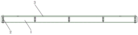
图1为钢-混凝土组合梁的立面图。Figure 1 is an elevation view of a steel-concrete composite beam.
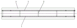
图2为钢-混凝土组合梁的平面图。Figure 2 is a plan view of a steel-concrete composite beam.
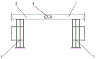
图3为钢-混凝土组合梁的横断面图。Figure 3 is a cross-sectional view of a steel-concrete composite beam.
图4为预制的钢-混凝土组合梁吊装就位的结构示意图。FIG. 4 is a schematic structural diagram of a prefabricated steel-concrete composite beam being hoisted into place.
图5为横向的钢-混凝土组合梁连接成跨梁体的结构示意图。FIG. 5 is a schematic structural diagram of a transverse steel-concrete composite beam connected to form a span beam body.
图6为横向相邻钢-混凝土组合梁的连接示意图。FIG. 6 is a schematic diagram of the connection of transversely adjacent steel-concrete composite beams.
图7为横向相邻混凝土桥面板之间的横向湿接缝的结构示意图。FIG. 7 is a schematic structural diagram of a transverse wet joint between transversely adjacent concrete bridge decks.
图8为纵向相邻钢-混凝土组合梁的连接示意图。FIG. 8 is a schematic diagram of the connection of longitudinally adjacent steel-concrete composite beams.
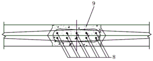
图9为纵向相邻混凝土桥面板之间的纵向湿接缝的结构示意图。FIG. 9 is a schematic structural diagram of a longitudinal wet joint between longitudinally adjacent concrete bridge decks.
图10为图8中a-a的剖面示意图。FIG. 10 is a schematic cross-sectional view of a-a in FIG. 8 .
图11为图10中b-b的剖面示意图。FIG. 11 is a schematic cross-sectional view of b-b in FIG. 10 .
图中部件标号如下:The part numbers in the figure are as follows:
1钢梁1 steel beam
2横梁2 beams
3混凝土桥面板3 Concrete bridge deck
4横向湿接缝4 Lateral Wet Seams
5纵向贯通钢筋5 Longitudinal through steel bars
6 C80高性能混凝土6 C80 High Performance Concrete
7纵向湿接缝7 Longitudinal wet seams
8横向贯通钢筋8 Transverse through steel bars
9 C150高性能混凝土9 C150 High Performance Concrete
10拼接钢板10 spliced steel plates
11高强螺栓。11 high-strength bolts.
具体实施方式Detailed ways
以下结合附图详细说明本发明的具体实施方式,使本领域的技术人员更清楚地理解如何实践本发明。尽管结合其优选的具体实施方案描述了本发明,但这些实施方案只是阐述,而不是限制本发明的范围。The specific embodiments of the present invention are described in detail below with reference to the accompanying drawings, so that those skilled in the art can more clearly understand how to practice the present invention. Although the invention has been described in conjunction with its preferred specific embodiments, these embodiments are intended to illustrate, and not to limit, the scope of the invention.
一种快速化安装的钢-混凝土组合梁桥,包括数片钢-混凝土组合梁。参见图1至图3,所述钢-混凝土组合梁包括两根平行的钢梁1、连接两根钢梁1的数根横梁2、以及浇筑于两根钢梁1的顶板上的一混凝土桥面板3。横向数片所述钢-混凝土组合梁连接成跨梁体,纵向数个所述跨梁体连接成桥梁。A steel-concrete composite girder bridge for rapid installation includes several steel-concrete composite girder. 1 to 3, the steel-concrete composite beam includes two
与现有技术的区别之处在于,所述钢-混凝土组合梁的混凝土桥面板3的四边外露有环形搭接钢筋。The difference from the prior art is that the four sides of the
参见图5至图7,在横向数片所述钢-混凝土组合梁之间的横向接缝处,横向相邻混凝土桥面板3的环形搭接钢筋中穿入有数根纵向贯通钢筋,横向相邻混凝土桥面板3之间采用高性能混凝土浇筑横向湿接缝4。Referring to FIGS. 5 to 7 , at the transverse joints between several pieces of the steel-concrete composite beams in the transverse direction, several longitudinal penetrating steel bars are inserted into the annular lap reinforcement bars of the transversely adjacent
参见图8至图11,在纵向数个跨梁体之间的纵向接缝处,纵向相邻混凝土桥面板3的环形搭接钢筋中穿入有数根横向贯通钢筋8,纵向相邻混凝土桥面板3之间采用高性能混凝土浇筑纵向湿接缝7,纵向相邻钢梁1的底板通过拼接钢板10配合高强螺栓11相连接。Referring to Figures 8 to 11, at the longitudinal joints between several longitudinal span beam bodies, several transverse penetrating
传统的连续组合梁桥在中支点地方的负弯矩是通过钢梁1和混凝土组成的全断面来承受的,也就是在中支点的地方钢梁1和混凝土都是连续通过的。而本钢-混凝土组合梁桥在中支点位置仅考虑对应的纵向混凝土桥面板3之间的连接和纵向钢梁1的底板之间的连接,通过混凝土桥面板3和钢梁1的底板来承受中支点负弯矩,从而将中支点负弯矩转化为一对力偶,由混凝土桥面板3和钢梁1底板分别承受拉力和压力,是一种新型连续组合梁桥的结构。The negative bending moment of the traditional continuous composite girder bridge at the mid-fulcrum is borne by the full section composed of
一种快速化安装钢-混凝土组合梁桥的施工方法,包括以下步骤:A construction method for rapid installation of a steel-concrete composite girder bridge, comprising the following steps:
(1)预制钢-混凝土组合梁,将预制好的钢-混凝土组合梁运输至现场,并通过吊车吊装就位于已经施工完成的盖梁上,吊装就位的示意图参见图4。其中,预制单片钢-混凝土组合梁包括以下步骤:在钢结构加工厂加工钢梁1;将两根钢梁1平行设置,并通过等间距设置的数根横梁2焊接连接;在两根钢梁1的顶板上搭设模板,浇筑混凝土桥面板3,同时使混凝土桥面板的四边外露环形搭接钢筋3,其中,两根钢梁1和混凝土桥面板3的横断面呈Π形结构。(1) Prefabricated steel-concrete composite beam, transport the prefabricated steel-concrete composite beam to the site, and hoist it on the completed cover beam by crane. See Figure 4 for the schematic diagram of the hoisting in place. Wherein, the prefabricated single-piece steel-concrete composite beam includes the following steps: processing the
(2)参见图5至图7,横向数片钢-混凝土组合梁吊装就位后,在横向数片钢-混凝土组合梁之间的横向接缝处,将数根纵向贯通钢筋5穿入横向相邻混凝土桥面板3的环形搭接钢筋中,采用高性能混凝土对横向相邻混凝土桥面板3之间浇筑横向湿接缝4,从而使横向数片钢-混凝土组合梁连接成跨梁体。(2) Referring to Figure 5 to Figure 7, after several horizontal steel-concrete composite beams are hoisted into place, at the horizontal joints between several horizontal steel-concrete composite beams, several longitudinal penetrating
(3)参见图8至图11,纵向数个跨梁体各自的数片钢-混凝土组合梁连接成整体后,在纵向数个跨梁体之间的纵向接缝处,将数根横向贯通钢筋8穿入纵向相邻混凝土桥面板3的环形搭接钢筋中,采用高性能混凝土对纵向相邻混凝土桥面板3之间浇筑纵向湿接缝7,采用拼接钢板10配合高强螺栓11连接纵向相邻钢梁1的底板,从而使纵向数个跨梁体连接成桥梁。(3) Referring to Figures 8 to 11, after several pieces of steel-concrete composite beams of several longitudinal span beam bodies are connected into a whole, at the longitudinal joints between several longitudinal span beam bodies, several transverse penetrating
(4)施工桥面系及护栏,成桥。(4) Construction of bridge deck and guardrail to complete the bridge.
本实施例以标准桥宽22m,跨径30m的桥梁高架形式为例。In this embodiment, an elevated bridge with a standard bridge width of 22m and a span of 30m is used as an example.
单片钢-混凝土组合梁的宽度为5.34m,钢-混凝土组合梁的钢梁1为工字钢且高1.48m,两根钢梁1之间的间距为2.82m,钢-混凝土组合梁的横梁2为工字钢且高0.7m,混凝土桥面板3的厚度为22cm。The width of the single-piece steel-concrete composite beam is 5.34m, the
纵向贯通钢筋5的直径为25mm且数量为6根,横向湿接缝4的宽度为30cm且其采用C80高性能混凝土6浇筑。钢-混凝土组合梁之间的横向接缝处的环形搭接钢筋中穿入数根纵向贯通钢筋5,能保证横向湿接缝4的强度大于该处钢筋的屈服强度。The diameter of the longitudinal through
横向贯通钢筋8的直径为25mm且数量为10根,纵向湿接缝7的宽度为50cm且其采用C150高性能混凝土9浇筑,钢-混凝土组合梁之间的纵向接缝处的环形搭接钢筋中穿入数根横向贯通钢筋8,能保证纵向湿接缝7的强度大于该处钢筋的屈服强度。The diameter of the transverse penetrating
纵向相邻钢梁1之间的拼接钢板10上采用36颗M24剪扭型高强螺栓11,由于空间限制,纵向相邻钢梁1之间仅在底板范围内进行螺栓连接,螺栓连接强度不小于连接截面的强度,按等强设计,底板上布置24颗高强螺栓11,剩余12颗高强螺栓11布置于腹板上。36 M24 shear-torsional high-
通过本施工方法施工的钢-混凝土组合梁桥将墩顶负弯矩转化为一对力偶通过混凝土桥面板与钢梁底板共同承受,混凝土桥面板通过配筋按轴心受拉构件计算,控制了裂缝宽度,避免了传统支座顶升或施加预应力等繁琐的施工步骤。The steel-concrete composite girder bridge constructed by this construction method converts the negative bending moment at the top of the pier into a pair of force couples, which are jointly supported by the concrete bridge deck and the steel girder bottom plate. The crack width avoids the tedious construction steps such as traditional bearing jacking or prestressing.
应当指出,对于经充分说明的本发明来说,还可具有多种变换及改型的实施方案,并不局限于上述实施方式的具体实施例。上述实施例仅仅作为本发明的说明,而不是对本发明的限制。总之,本发明的保护范围应包括那些对于本领域普通技术人员来说显而易见的变换或替代以及改型。It should be pointed out that, for the fully described invention, various alternative and modified embodiments are possible and are not limited to the specific examples of the above-described embodiments. The above-mentioned embodiments are only used as an illustration of the present invention, rather than a limitation of the present invention. In a word, the protection scope of the present invention should include those changes or substitutions and modifications that are obvious to those of ordinary skill in the art.
Claims (6)
Priority Applications (1)
| Application Number | Priority Date | Filing Date | Title |
|---|---|---|---|
| CN201911033359.8A CN110863417A (en) | 2019-10-28 | 2019-10-28 | A fast-installed steel-concrete composite girder bridge and its construction method |
Applications Claiming Priority (1)
| Application Number | Priority Date | Filing Date | Title |
|---|---|---|---|
| CN201911033359.8A CN110863417A (en) | 2019-10-28 | 2019-10-28 | A fast-installed steel-concrete composite girder bridge and its construction method |
Publications (1)
| Publication Number | Publication Date |
|---|---|
| CN110863417A true CN110863417A (en) | 2020-03-06 |
Family
ID=69653676
Family Applications (1)
| Application Number | Title | Priority Date | Filing Date |
|---|---|---|---|
| CN201911033359.8A Pending CN110863417A (en) | 2019-10-28 | 2019-10-28 | A fast-installed steel-concrete composite girder bridge and its construction method |
Country Status (1)
| Country | Link |
|---|---|
| CN (1) | CN110863417A (en) |
Cited By (6)
| Publication number | Priority date | Publication date | Assignee | Title |
|---|---|---|---|---|
| CN112391931A (en) * | 2020-10-30 | 2021-02-23 | 山东高速城投绕城高速公路有限公司 | Assembly type continuous T-beam bridge splicing section adopting UHPC shear keys and construction method |
| CN112458877A (en) * | 2020-11-25 | 2021-03-09 | 广州市市政工程设计研究总院有限公司 | Assembled steel-concrete combined rigid frame bridge and construction method thereof |
| CN112502023A (en) * | 2020-11-25 | 2021-03-16 | 广州市市政工程设计研究总院有限公司 | Slot-connected steel-concrete combined rigid frame bridge and construction method thereof |
| CN112962416A (en) * | 2021-02-25 | 2021-06-15 | 四川省公路规划勘察设计研究院有限公司 | Steel plate girder bridge suitable for mountain area construction and construction method thereof |
| CN115110417A (en) * | 2022-06-30 | 2022-09-27 | 上海市政工程设计研究总院(集团)有限公司 | Steel concrete combined bridge deck segment connecting structure for rapid construction |
| CN116537058A (en) * | 2023-03-31 | 2023-08-04 | 中铁二院工程集团有限责任公司 | Construction method of T-bridge of steel-concrete composite beam |
Citations (10)
| Publication number | Priority date | Publication date | Assignee | Title |
|---|---|---|---|---|
| CN103924505A (en) * | 2014-05-07 | 2014-07-16 | 河南省交通规划勘察设计院有限责任公司 | Prefabricated steel-concrete combination T beam with corrugated steel web and construction method |
| CN105986545A (en) * | 2015-01-29 | 2016-10-05 | 同济大学 | Prefabricated composite beam segment connecting structure and application thereof |
| CN106677049A (en) * | 2017-01-20 | 2017-05-17 | 福州大学 | Assembled steel-concrete combination structure bridge and construction method |
| CN108221634A (en) * | 2018-03-16 | 2018-06-29 | 中交高新科技产业发展有限公司 | The Wavelike steel webplate I-shaped composite beam bridge of maximum assembling |
| CN207933865U (en) * | 2018-02-09 | 2018-10-02 | 中交第二航务工程局有限公司 | Hogging moment area uses the assembled combination beam of UHPC floorings |
| CN109082998A (en) * | 2018-07-05 | 2018-12-25 | 湖南省交通规划勘察设计院有限公司 | Integral prefabricated steel plate combination girder construction and construction method |
| CN109440642A (en) * | 2018-11-30 | 2019-03-08 | 中铁第四勘察设计院集团有限公司 | Steel reinforced concrete composite beam bridge panel assembly seam construction based on early strong high performance concrete |
| CN109487686A (en) * | 2018-12-29 | 2019-03-19 | 武汉理工大学 | A kind of unit construction bridge panel transverse joint using UHPC grouting material |
| CN110241724A (en) * | 2019-05-29 | 2019-09-17 | 中交第二公路勘察设计研究院有限公司 | A kind of hogging moment area UHPC processing steel-mixes composite structure and preparation method |
| CN211735002U (en) * | 2019-10-28 | 2020-10-23 | 上海市政工程设计研究总院(集团)有限公司 | Steel-concrete combined beam bridge capable of being installed quickly |
-
2019
- 2019-10-28 CN CN201911033359.8A patent/CN110863417A/en active Pending
Patent Citations (10)
| Publication number | Priority date | Publication date | Assignee | Title |
|---|---|---|---|---|
| CN103924505A (en) * | 2014-05-07 | 2014-07-16 | 河南省交通规划勘察设计院有限责任公司 | Prefabricated steel-concrete combination T beam with corrugated steel web and construction method |
| CN105986545A (en) * | 2015-01-29 | 2016-10-05 | 同济大学 | Prefabricated composite beam segment connecting structure and application thereof |
| CN106677049A (en) * | 2017-01-20 | 2017-05-17 | 福州大学 | Assembled steel-concrete combination structure bridge and construction method |
| CN207933865U (en) * | 2018-02-09 | 2018-10-02 | 中交第二航务工程局有限公司 | Hogging moment area uses the assembled combination beam of UHPC floorings |
| CN108221634A (en) * | 2018-03-16 | 2018-06-29 | 中交高新科技产业发展有限公司 | The Wavelike steel webplate I-shaped composite beam bridge of maximum assembling |
| CN109082998A (en) * | 2018-07-05 | 2018-12-25 | 湖南省交通规划勘察设计院有限公司 | Integral prefabricated steel plate combination girder construction and construction method |
| CN109440642A (en) * | 2018-11-30 | 2019-03-08 | 中铁第四勘察设计院集团有限公司 | Steel reinforced concrete composite beam bridge panel assembly seam construction based on early strong high performance concrete |
| CN109487686A (en) * | 2018-12-29 | 2019-03-19 | 武汉理工大学 | A kind of unit construction bridge panel transverse joint using UHPC grouting material |
| CN110241724A (en) * | 2019-05-29 | 2019-09-17 | 中交第二公路勘察设计研究院有限公司 | A kind of hogging moment area UHPC processing steel-mixes composite structure and preparation method |
| CN211735002U (en) * | 2019-10-28 | 2020-10-23 | 上海市政工程设计研究总院(集团)有限公司 | Steel-concrete combined beam bridge capable of being installed quickly |
Cited By (6)
| Publication number | Priority date | Publication date | Assignee | Title |
|---|---|---|---|---|
| CN112391931A (en) * | 2020-10-30 | 2021-02-23 | 山东高速城投绕城高速公路有限公司 | Assembly type continuous T-beam bridge splicing section adopting UHPC shear keys and construction method |
| CN112458877A (en) * | 2020-11-25 | 2021-03-09 | 广州市市政工程设计研究总院有限公司 | Assembled steel-concrete combined rigid frame bridge and construction method thereof |
| CN112502023A (en) * | 2020-11-25 | 2021-03-16 | 广州市市政工程设计研究总院有限公司 | Slot-connected steel-concrete combined rigid frame bridge and construction method thereof |
| CN112962416A (en) * | 2021-02-25 | 2021-06-15 | 四川省公路规划勘察设计研究院有限公司 | Steel plate girder bridge suitable for mountain area construction and construction method thereof |
| CN115110417A (en) * | 2022-06-30 | 2022-09-27 | 上海市政工程设计研究总院(集团)有限公司 | Steel concrete combined bridge deck segment connecting structure for rapid construction |
| CN116537058A (en) * | 2023-03-31 | 2023-08-04 | 中铁二院工程集团有限责任公司 | Construction method of T-bridge of steel-concrete composite beam |
Similar Documents
| Publication | Publication Date | Title |
|---|---|---|
| CN110863417A (en) | A fast-installed steel-concrete composite girder bridge and its construction method | |
| CN103924505B (en) | Use prefabricated steel-concrete combination T beam and the construction method of Wavelike steel webplate | |
| CN105002816B (en) | Prefabricated and assembled fish-belly I-shaped prestressed steel-concrete composite continuous girder bridge and its construction method | |
| CN106677049A (en) | Assembled steel-concrete combination structure bridge and construction method | |
| CN108677685A (en) | A kind of ultra-high performance concrete-part girder steel combination bent cap and its construction method | |
| CN108867310A (en) | The short rib T beam bridge of pretensioning prestressed concrete and its construction method | |
| WO2022188666A1 (en) | Combined bridge deck structure for bridge, and bridge structure and construction method therefor | |
| CN104032668B (en) | Half-through steel purlin-Combined concrete continuous steel frame bridge | |
| CN211735002U (en) | Steel-concrete combined beam bridge capable of being installed quickly | |
| CN207846187U (en) | A kind of Wavelike steel webplate I-shaped composite beam bridge of maximum assembling | |
| CN111877182B (en) | Novel construction method for upper structure of multi-chamber continuous UHPC box girder bridge | |
| CN105064200B (en) | Prefabricated and assembled fish-belly truss prestressed steel-concrete composite simply supported beam bridge and its construction method | |
| CN106930181A (en) | A kind of simple-supported thencontinuous steel reinforced concrete combined bridge hogging moment area structure | |
| CN113653235A (en) | Laminated slab, connecting structure of laminated slab and combination beam and construction method | |
| CN207973983U (en) | It can rapidly-assembled precast bridge | |
| CN105064195B (en) | The fish belly Wavelike steel webplate prestressing with bond steel reinforced concrete combination simply supported girder bridge and its construction method of precast assembly | |
| CN111254800A (en) | A composite beam suitable for urban bridges and its construction method | |
| CN112982139A (en) | Wide-width large-span hybrid beam and short-tower cable-stayed bridge system and construction method thereof | |
| CN217974005U (en) | Combined box girder structure | |
| CN206902913U (en) | A kind of high-altitude long-span overhung structure | |
| CN112982162A (en) | Steel bar truss type steel-concrete combined bridge deck and construction method | |
| CN111979891A (en) | A kind of semi-penetrating rectangular steel tube concrete composite truss bridge and construction method | |
| CN205188793U (en) | Prefabricated fish belly I shape prestressing force steel and concrete composite continuous bridge of assembling | |
| CN219671054U (en) | An integrally hoisted, prefabricated steel-concrete composite small box beam | |
| CN209816632U (en) | Arch foot structure for special-shaped space arch bridge |
Legal Events
| Date | Code | Title | Description |
|---|---|---|---|
| PB01 | Publication | ||
| PB01 | Publication | ||
| SE01 | Entry into force of request for substantive examination | ||
| SE01 | Entry into force of request for substantive examination |