CN110860543A - Automatic cleaning device for oil sample ferrographic analysis glass test tube - Google Patents
Automatic cleaning device for oil sample ferrographic analysis glass test tube Download PDFInfo
- Publication number
- CN110860543A CN110860543A CN201911123451.3A CN201911123451A CN110860543A CN 110860543 A CN110860543 A CN 110860543A CN 201911123451 A CN201911123451 A CN 201911123451A CN 110860543 A CN110860543 A CN 110860543A
- Authority
- CN
- China
- Prior art keywords
- test tube
- motor
- cleaning
- cleaning agent
- unit
- Prior art date
- Legal status (The legal status is an assumption and is not a legal conclusion. Google has not performed a legal analysis and makes no representation as to the accuracy of the status listed.)
- Granted
Links
Images


Classifications
-
- B—PERFORMING OPERATIONS; TRANSPORTING
- B08—CLEANING
- B08B—CLEANING IN GENERAL; PREVENTION OF FOULING IN GENERAL
- B08B9/00—Cleaning hollow articles by methods or apparatus specially adapted thereto
- B08B9/08—Cleaning containers, e.g. tanks
- B08B9/20—Cleaning containers, e.g. tanks by using apparatus into or on to which containers, e.g. bottles, jars, cans are brought
- B08B9/28—Cleaning containers, e.g. tanks by using apparatus into or on to which containers, e.g. bottles, jars, cans are brought the apparatus cleaning by splash, spray, or jet application, with or without soaking
-
- B—PERFORMING OPERATIONS; TRANSPORTING
- B08—CLEANING
- B08B—CLEANING IN GENERAL; PREVENTION OF FOULING IN GENERAL
- B08B9/00—Cleaning hollow articles by methods or apparatus specially adapted thereto
- B08B9/08—Cleaning containers, e.g. tanks
- B08B9/20—Cleaning containers, e.g. tanks by using apparatus into or on to which containers, e.g. bottles, jars, cans are brought
- B08B9/36—Cleaning containers, e.g. tanks by using apparatus into or on to which containers, e.g. bottles, jars, cans are brought the apparatus cleaning by using brushes
Landscapes
- Engineering & Computer Science (AREA)
- Mechanical Engineering (AREA)
- Cleaning In General (AREA)
Abstract
An automatic cleaning device for an oil sample ferrography glass test tube belongs to the field of oil analysis. The device comprises a test tube clamp unit, a cleaning agent adding unit, a scrubbing unit, a clear water washing unit, a control unit and a shell, wherein the test tube clamp unit is fixed on a clamp supporting plate which is fixed with the shell; the cleaning agent adding unit is fixed with the first catheter fixing frame, the first catheter fixing frame and the shell are fixed, the test tube brush is driven to rotate at a high speed through the motor, the inner wall of the test tube is scrubbed by the mixed cleaning agent with generated scouring force, and the purpose of thoroughly cleaning the test tube is achieved through the flushing unit. The automatic cleaning machine is simple and safe to operate, can realize automatic cleaning after parameters are designed, is high in cleaning efficiency, realizes quantitative use of the cleaning agent, avoids waste, and greatly liberates workers.
Description
Technical Field
The invention relates to the field of oil analysis, in particular to an automatic cleaning device for an oil sample ferrography analysis glass test tube.
Background
The oil sample ferrography analysis technology is an oil sample analysis method which utilizes an iron spectrometer to separate and detect abrasive particles and debris from a lubricating oil (grease) sample so as to analyze and judge the wear type, the wear degree and the wear part of a mechanical kinematic pair. When carrying out ferrography, because the viscosity of the equipment oil of using is generally great, in order to improve efficiency and the quality of preparation tablet, need absorb tetrachloroethylene solvent and fluid according to certain dilution ratio and place glass test tube in and mix evenly. When the operating condition of mechanical equipment is analyzed by utilizing the ferrographic technology, the quantity of the collected oil samples is generally large, and the oil samples comprise oil samples at different positions and oil samples at the same position under different operating times. In order to avoid the influence of the mixing of the oil samples on the analysis result, a test tube is required to be used for one oil sample during spectrum preparation. Thus, after a batch of oil samples has been analyzed, the number of tubes used is large. In order to avoid the long-time deposition of residual oil on the inner wall of the test tube and prepare for the next experiment, the test tube needs to be cleaned in time.
Currently, there are two main methods for cleaning glass test tubes in the laboratory:
(1) and cleaning by using an ultrasonic cleaning machine. Because the viscosity of the oil used by the equipment is generally higher, the difficulty of cleaning the residual oil in the test tube by using ultrasonic waves is higher, and a cleaning agent is more consumed; in addition, the stripped oil can float in the cleaning tank and is easily adhered to the inner wall and the outer wall of the test tube again, so that the test tube is difficult to clean completely.
(2) And (4) manually cleaning. Adding a cleaning agent into the test tube to be cleaned, manually brushing the test tube by using a brush, and then washing the test tube by using clear water. The disadvantages are as follows: in the manual cleaning process, if the operation is not proper, the test tube is broken, so that the test tube is easy to damage experimenters, and polluted oil or cleaning agent is easy to cause infection; in addition, the experimenter needs to spend certain time cleaning the test tube, which wastes time and labor and has low cleaning efficiency.
Disclosure of Invention
The invention aims to solve the problems that the cleaning method cannot thoroughly clean the test tube, and wastes time, labor and high risk, and provides an automatic cleaning device for the oil sample ferrography analysis glass test tube.
The technical scheme adopted by the invention for solving the problems is as follows: the utility model provides an oil appearance ferrography analysis glass test tube's self-cleaning device which characterized in that: comprises a test tube clamp unit, a cleaning agent adding unit, a brushing unit, a clear water washing unit, a control unit and a shell.
The test tube clamp unit is fixed on a clamp supporting plate, and the clamp supporting plate is fixed with the shell; the cleaning agent adding unit is fixed on the side wall of the shell through a first conduit fixing frame; the brushing unit is fixed with the first supporting plate and the second supporting plate, and the first supporting plate and the second supporting plate are fixed with the shell; the clear water washing unit is fixed on the side wall of the shell through a second catheter fixing frame; the control unit is fixed on the second supporting plate.
The test tube clamp unit comprises a main fixing table, a positioning nut, a spring and a test tube clamping block; the main fixing table is cylindrical, three grooves are designed on the upper end face of the main fixing table, an included angle of 120 degrees is formed between every two adjacent grooves, and a plurality of groups of positioning holes are formed in the lower end face of the main fixing table and are convenient to connect with the clamp supporting plate; three positioning nuts are arranged at the tail ends of the corresponding grooves respectively; the three springs are respectively arranged between the positioning nut and the test tube clamping block; the test tube fixture block on be equipped with the rubber band kerve, if when requiring highly to fixed test tube, the locking force to the test tube is increased to the right amount of rubber band of accessible winding.
The cleaning agent adding unit comprises a cleaning agent pump, a cleaning rubber conduit, a plastic cleaning conduit and a cleaning agent tank; the cleaning agent pump be located the cleaning agent inslot, and with the one end of washing rubber pipe link to each other, the other end of washing rubber pipe with plasticity wash the pipe connection, plasticity wash the pipe other end and be conical shower nozzle, be located the upper left side of waiting to wash the test tube.
The brushing unit comprises a first motor, a first coupler, a lead screw, a nut, a first optical axis, a second motor, a motor supporting plate, an upper limit switch, a second coupler, a test tube brush and a lower limit switch; the lead screw with first optical axis, second optical axis fix first backup pad, second backup pad between, and with the motor backup pad be connected, first motor pass through first shaft coupling with lead screw connection, the lead screw be connected with the nut, the nut is connected with the motor backup pad, the second motor is fixed in the motor backup pad, the second motor pass through the second shaft coupling be connected with the test-tube brush, upper and lower limit switch fix on the casing. The first motor drives the screw rod to rotate through the first coupler to realize the up-and-down movement of the motor supporting plate, the upper limit switch and the lower limit switch limit the stroke of the motor supporting plate, so that the lowest position of the test tube brush is arranged at the bottom of a test tube, and the highest position is convenient for taking and placing the test tube. The second motor can set different rotating speeds to meet the cleaning requirements of test tubes with different pollution degrees. Through the second coupling realize being connected between second motor and the test tube brush, can realize looking the pipe and trade the brush, be convenient for to the washing of different specification test tubes. The test tube brush requires that the length of the brush hair is certain and long enough, so that other associated effects can be reduced.
The clean water flushing unit comprises a clean water tank, a flushing pump, a flushing rubber catheter and a plastic flushing catheter; the washing pump is positioned in the clean water tank and is connected with one end of the washing rubber catheter, the other end of the washing rubber catheter is connected with the plastic washing catheter, and the other end of the plastic washing catheter is a conical nozzle and is positioned at the upper right part of the test tube to be washed.
The control unit controls the cleaning agent pump, the first motor, the second motor and the flushing pump through programs so as to respectively control the adding amount of the cleaning agent, the rotating speed of the test tube brush, the brushing time of the test tube and the flushing time of clear water.
The casing for self-cleaning mechanical device's whole appearance design, its bottom plate design has certain inclination to be equipped with the leakage fluid dram at the bottom plate middle part, the waste liquid of being convenient for collects the discharge, the casing take the omniseal all around, avoid the waste liquid spill, the casing openly choose transparent material for use, be convenient for observe inside behavior, casing back design be two recesses, place cleaner groove and clear water groove.
Furthermore, the cleaning agent pump and the flushing pump can be correspondingly installed with the cleaning agent tank and the clear water tank, so that the whole machine can be conveniently moved, and can also be directly installed on a corresponding pipeline in a laboratory, and the need of adding the cleaning agent and the clear water is reduced.
Furthermore, the plastic cleaning catheter and the plastic flushing catheter can be manually bent to adjust the position of the spray head according to the required cleaning requirement.
Furthermore, the control unit is provided with an alarm system, and the cleaning work of one test tube can be prompted after the cleaning work is finished, or the alarm prompt is given when the device breaks down.
Compared with the existing cleaning mode, the cleaning method has the following advantages:
firstly, not too much manual operation is needed, and experimenters are liberated.
Second, can rinse clean test tube, reduce the waste of cleaner more efficiently.
Thirdly, can avoid among the cleaning process noxious material or test tube damage to cause infection and injury to the experimenter, reduce the work danger.
Drawings
Fig. 1 is a front view of the overall structure of the present invention.
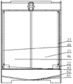
Fig. 2 is a rear view of the overall structure of the present invention.
Fig. 3 is a front view of the test tube clamp unit structure of the present invention.
Fig. 4 is a top view of the test tube fixture unit structure of the present invention.
Fig. 5 is a left side view of the structure of the cleaning agent adding unit of the present invention.
Fig. 6 is a left side view of the brush unit structure of the present invention.
Fig. 7 is a right side view of the fresh water flush unit structure of the present invention.
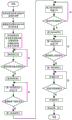
Fig. 8 is a flow chart of the operation of the present invention.
Description of reference numerals:
1-a test tube clamp unit, 2-a cleaning agent adding unit, 3-a brushing unit, 4-a clear water washing unit, 5-a control unit, 6-a shell, 7-a clamp supporting plate, 8-a second supporting plate, 9-a first catheter fixing frame, 10-a second catheter fixing frame, 11-a first supporting plate, 12-a main fixing table, 13-a positioning nut, 14-a spring, 15-a test tube clamping block, 16-a groove, 21-a cleaning agent groove, 22-a cleaning agent pump, 23-a cleaning rubber catheter, 24-a plastic cleaning catheter, 31-a first motor, 32-a first coupler, 33-a lead screw, 34-a nut, 35-a first optical axis, 36-a second optical axis, 37-a second motor, 38-motor supporting plate, 39-upper limit switch, 40-second coupling, 41-test tube brush, 42-lower limit switch, 43-washing pump, 44-washing rubber conduit, 45-plastic washing conduit, 46-clear water tank, 61-bottom plate and 62-liquid outlet.
Detailed Description
For a fuller understanding of the technical aspects of the present invention, reference should be made to the following detailed description taken together with the accompanying drawings.
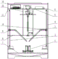
Referring to fig. 1 and 2, the automatic cleaning device for the oil sample ferrography analysis glass test tube comprises a test tube clamp unit 1, a cleaning agent adding unit 2, a brushing unit 3, a clear water washing unit 4, a control unit 5 and a shell 6. The test tube clamp unit 1 is fixed on a clamp support plate 7, and the clamp support plate 7 is fixed with the shell 6; the cleaning agent adding unit 2 is fixed on the side wall of the shell 6 through a first conduit fixing frame 9; the brushing unit 3 is fixed with a first supporting plate 8 and a second supporting plate 11, and the first supporting plate 8 and the second supporting plate 11 are fixed on the shell 6; the clear water washing unit 4 is fixed on the side wall of the shell 6 through a second catheter fixing frame 10; the control unit 5 is fixed on the second support plate 11.
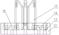
As shown in fig. 3 and 4, the test tube clamp unit 1 includes a main fixing table 12, a positioning nut 13, a spring 14, and a test tube clamping block 15. The main fixing table 12 is cylindrical, three grooves 16 are designed on the upper end face of the main fixing table, included angles of 120 degrees are formed between every two adjacent grooves 16, multiple groups of positioning holes are formed in the lower end face of the main fixing table and are conveniently connected with the clamp supporting plate 7, three positioning nuts 13 are respectively placed at the tail ends of the corresponding grooves 16, and three springs 14 are respectively placed between the corresponding positioning nuts 13 and the test tube clamping blocks 15. Be equipped with the rubber band kerve on test tube fixture block 15, if when higher to fixed test tube requirement, the right amount rubber band of accessible winding increases the locking force to the test tube, ensures that can not get rid of under the drive of high-speed rotatory test-tube brush and flies. The whole test tube clamp unit is an elastic device, and the test tube is fixed by spring force, namely, the test tube is fixed immediately.
As shown in fig. 5, the cleaning agent adding unit 2 includes a cleaning agent tank 21, a cleaning agent pump 22, a cleaning rubber conduit 23, and a plastic cleaning conduit 24. The cleaning agent pump 22 is positioned in the cleaning agent groove 21 and is connected with one end of the cleaning rubber guide pipe 23, the other end of the cleaning rubber guide pipe 23 is connected with the plastic cleaning guide pipe 24, and the other end of the plastic cleaning guide pipe 24 is a conical nozzle positioned at the upper left part of the test tube to be cleaned. The nozzle position of the plastic cleaning conduit 24 is adjusted, a certain amount of cleaning agent is sucked from the cleaning agent groove 21 by the cleaning agent pump 22, and the cleaning agent is conveyed into the test tube to be cleaned through the plastic cleaning conduit 24.
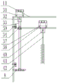
As shown in fig. 6, the brushing unit 3 includes a first motor 31, a first coupling 32, a screw 33, a nut 34, a first optical axis 35, a second optical axis 36, a second motor 37, a motor support plate 38, an upper limit switch 39, a second coupling 40, a test tube brush 41, and a lower limit switch 42. Lead screw 33 and first optical axis 35, second optical axis 36 is fixed between first backup pad 8, second backup pad 11, a left and right sides rotation for restricting motor backup pad 38, first motor 31 is connected with lead screw 33 through first shaft coupling 32, lead screw 33 is connected with nut 34, nut 34 is connected with motor backup pad 38, second motor 37 is fixed on motor backup pad 38, second motor 37 realizes being connected between second motor 37 and test-tube brush 41 through second shaft coupling 40, can realize that the sight tube trades the brush, be convenient for to the washing of different specification test tubes, still can set up the washing requirement of different rotational speeds realization to the test tube of different pollution degrees through second motor 37, drive test-tube brush 41 high-speed rotation through second motor 37, mix the cleaner, thoroughly scrub the remaining oil sample of test tube inner wall. The first motor 31 drives the screw 33 to rotate through the first coupler 32 to realize the up-and-down movement of the motor supporting plate 38, the stroke of the motor supporting plate 38 is limited through the upper limit switch 39 and the lower limit switch 42 which are fixed on the shell 6, so that the lowest position of the test tube brush 41 is at the bottom of the test tube, the highest position is convenient for taking and placing the test tube, the length of the bristles of the test tube brush 41 is required to be certain and long enough, and other related effects can be reduced.
As shown in fig. 7, the clean water flushing unit 4 includes a flushing pump 43, a flushing rubber conduit 44, a plastic flushing conduit 45 and a clean water tank 46. The washing pump 43 is located in the clean water tank 46 and connected with one end of the washing rubber conduit 44, the other end of the washing rubber conduit 44 is connected with the plastic washing conduit 45, and the other end of the plastic washing conduit 45 is a conical nozzle located at the upper right of the test tube to be washed. The nozzle position of the plastic flushing catheter 45 is adjusted, a certain amount of clean water is sucked from the clean water tank 46 by the flushing pump 43, and the test tube which is washed is flushed through the plastic flushing catheter 45.
The control unit 5 controls the cleaning agent pump 22, the first motor 31, the second motor 37 and the washing pump 43 through programs, so as to respectively control the addition amount of the cleaning agent, the rotation speed of the test tube brush, the brushing time of the test tube and the washing time of the clean water. In addition, the control unit 5 is additionally provided with an alarm system for prompting after the cleaning work of one test tube is finished or giving an alarm when the device fails.
As shown in fig. 8, the program flow of the control unit 5: after the power is switched on, the adding amount of the cleaning agent, the rotating speed of the test tube brush, the brushing time of the test tube and the rinsing time of the clean water are set, and the device starts to work. The control unit 5 controls the cleaning agent pump 22 in the cleaning agent adding unit 2 to start working, and when the addition amount of the cleaning agent meets the requirement, the cleaning agent pump 22 stops; the control unit 5 controls the first motor 31 in the brushing unit 3 to start in the forward direction, and when the screw 33 drives the motor supporting plate 38 to descend and contact the lower limit switch 42, the first motor 31 stops; the control unit 5 controls the second motor 37 in the brushing unit 3 to start, executes the brushing task at a set rotating speed, and stops the second motor 37 after the brushing time is over; the control unit 5 controls the first motor 31 to start reversely, and when the screw 33 drives the motor supporting plate 38 to ascend and contact the upper limit switch 39, the first motor 31 stops; the control unit 5 controls the washing pump 43 in the clean water washing unit 4 to start working, and after the washing time is over, the washing pump 43 stops and the test tube washing work is finished.
The bottom plate 61 of the shell 6 is designed to have a certain inclination, and the middle part of the bottom plate is provided with a liquid outlet 62, so that waste liquid is collected and discharged conveniently; the periphery of the shell is fully sealed, so that waste liquid is prevented from splashing; the front surface of the shell is made of transparent materials, so that the internal working condition can be observed conveniently; the back of the shell is designed into two grooves for placing a cleaning agent groove 21 and a clean water groove 46.
The cleaning agent pump 22 and the flushing pump 43 can be correspondingly arranged with the cleaning agent groove 21 and the clear water groove 46, so that the whole machine can be conveniently moved, and can also be directly arranged on a corresponding pipeline of a laboratory, thereby reducing the need of adding the cleaning agent and the clear water; the plastic guide pipes 24 and 45 can be manually bent to adjust the positions of the spray heads according to the required cleaning requirements, so that a cleaning agent and clean water can be conveniently injected into the test tube to be cleaned.
The working principle of the invention is as follows: the test tube to be cleaned is fixed on the main fixing table 12 of the test tube clamp unit 6, and the positions of the nozzles of the plastic cleaning catheter 24 and the plastic rinsing catheter 45 are manually adjusted. And (3) closing a power switch, setting the addition amount of the cleaning agent, the rotating speed of the test tube brush, the brushing time of the test tube and the rinsing time of clear water through the control unit 5, and starting the device to work. The cleaning agent pump 22 is started, a certain amount of cleaning agent is sucked from the cleaning agent groove 21 and is conveyed into a test tube to be cleaned through the plastic cleaning conduit 24; the first motor 31 is started to drive the screw rod 33, and drive the motor supporting plate 38 to descend until the motor supporting plate contacts the lower limit switch 42, and then the motor supporting plate stops, and at the moment, the tail end of the test tube brush contacts the bottom of the test tube; the second motor 37 is started, the test tube brush 41 is driven to rotate at a high speed through the second coupler 40, and the mixed cleaning agent brushes the inner wall of the test tube; after the brushing time is over, the second motor 37 stops, the test tube brush 41 stops rotating, the first motor 31 starts reversely, the driving screw 33 drives the motor supporting plate 38 to ascend, further drives the test tube brush 41 to ascend, and stops ascending when contacting the upper limit switch 39, so that enough space is left for washing the test tube; the flush pump 43 starts, makes the clear water in the clear water tank 46 flow out through the plasticity washing pipe 45, washes the test tube that has been scrubbed, and the waste liquid flows out through the leakage fluid dram 62 at bottom plate 61 middle part, and up to the end of the washing time, the test tube is by the sanitization, and alarm device suggestion cleaning work is accomplished. And taking out the washed test tube, drying the test tube by using a dryer, finishing the complete cleaning process of one glass test tube, controlling other work flows through a control unit except for necessary manual operation, and repeating the process to continuously clean other glass test tubes.
The foregoing shows and describes the general principles, principal features, and advantages of the invention. The above examples of the invention are mainly intended to state the working principle thereof, and suitable variations and modifications can be made thereto without departing from the invention.
Claims (10)
1. The utility model provides an oil appearance ferrography analysis glass test tube's self-cleaning device which characterized in that: comprises a test tube clamp unit (1), a cleaning agent adding unit (2), a brushing unit (3), a clear water washing unit (4), a control unit (5) and a shell (6); the test tube clamp unit (1) is fixed on a clamp support plate (7), and the clamp support plate (7) is fixed with the shell (6); the cleaning agent adding unit (2) is fixed with the first catheter fixing frame (9), and the first catheter fixing frame (9) is fixed with the shell (6); the brushing unit (3) is fixed with the first supporting plate (8) and the second supporting plate (11), and the first supporting plate (8) and the second supporting plate (11) are fixed with the shell (6); the clean water washing unit (4) is fixed with a second catheter fixing frame (10), and the second catheter fixing frame (10) is fixed with the shell (6); the control unit (5) is fixed with the second support plate (11).
2. The automatic cleaning device for the oil sample ferrography glass test tube of claim 1, wherein: the test tube clamp unit (1) comprises a main fixing table (12), a positioning nut (13), a spring (14) and a test tube clamping block (15); the main fixing table (12) is cylindrical, three grooves (16) are designed on the upper end face of the main fixing table (12), an included angle of 120 degrees is formed between every two adjacent grooves (16), a plurality of groups of mounting positioning holes convenient to be connected with the clamp supporting plate (7) are formed in the lower end face of the main fixing table, three positioning nuts (13) are respectively placed at the tail ends of the three grooves (16), and three springs (14) are respectively placed between the corresponding positioning nuts (13) and the test tube clamping blocks (15); the test tube clamping block (15) is provided with a rubber band groove.
3. The automatic cleaning device for the oil sample ferrography glass test tube of claim 1, wherein: the cleaning agent adding unit (2) comprises a cleaning agent tank (21), a cleaning agent pump (22), a cleaning rubber conduit (23) and a plastic cleaning conduit (24); the cleaning agent pump (22) is positioned in the cleaning agent groove (21) and is connected with one end of the cleaning rubber conduit (23), the other end of the cleaning rubber conduit (23) is connected with one end of the plastic cleaning conduit (24), the other end of the plastic cleaning conduit (24) is a conical nozzle and is positioned above the left side of the test tube to be cleaned.
4. The automatic cleaning device for the oil sample ferrography glass test tube of claim 3, wherein: the cleaning agent pump (22) is arranged corresponding to the cleaning agent tank (21).
5. The automatic cleaning device for the oil sample ferrography glass test tube of claim 1, wherein: the brushing unit (3) comprises a first motor (31), a first coupler (32), a lead screw (33), a nut (34), a first optical axis (35), a second optical axis (36), a second motor (37), a motor supporting plate (38), an upper limit switch (39), a second coupler (40), a test tube brush (41) and a lower limit switch (42); the lead screw (33), the first optical axis (35) and the second optical axis (36) are fixed between the first support plate (8) and the second support plate (11) and used for limiting the left-right rotation of the motor support plate (38), the first motor (31) is connected with the lead screw (33) through the first coupler (32) and realizes the connection of the lead screw (33) and the motor support plate (38) through the nut (34), the second motor (37) is fixed on the motor support plate (38) and realizes the connection between the second motor (37) and the test tube brush (41) through the second coupler (40), the visual tube brush replacement is realized, the cleaning of test tubes with different specifications is facilitated, the test tube brush (41) is driven to rotate at high speed through the second motor (37), the first motor (31) drives the lead screw (33) to rotate through the first coupler (32) to realize the up-down movement of the motor support plate (38), the stroke of the motor supporting plate (38) is limited by an upper limit switch (39) and a lower limit switch (42) which are fixed on the shell (6), so that the lowest position of the test tube brush (41) is at the bottom of the test tube, the test tube is convenient to take and place at the highest position, and the length of the bristles of the test tube brush (41) is long enough.
6. The automatic cleaning device for the oil sample ferrography glass test tube of claim 1, wherein: the clean water washing unit (4) comprises a washing pump (43), a washing rubber conduit (44), a plastic washing conduit (45) and a clean water tank (46); the washing pump (43) is positioned in the clean water tank (46) and is connected with one end of the washing rubber catheter (44), the other end of the washing rubber catheter (44) is connected with the plastic washing catheter (45), and the other end of the plastic washing catheter (45) is a conical nozzle and is positioned at the upper right part of the test tube to be washed.
7. The automatic cleaning device for the oil sample ferrography glass test tube of claim 6, wherein: the flushing pump (43) is arranged corresponding to the clean water tank (46).
8. The automatic cleaning device for the oil sample ferrography glass test tube of claim 1, wherein: the control unit controls the cleaning agent pump (22), the first motor (31), the second motor (37) and the flushing pump (43) through a computer program, so as to respectively control the addition amount of the cleaning agent, the rotating speed of the test tube brush, the brushing time of the test tube and the flushing time of clear water.
9. The automatic cleaning device for the oil sample ferrography glass test tube of claim 1, wherein: a bottom plate (61) of the shell (6) is inclined, and a liquid discharge port (62) is formed in the middle of the bottom plate, so that waste liquid is collected and discharged conveniently; the periphery is fully sealed; the front surface is made of transparent material, so that the internal working condition can be observed conveniently; the back of the shell is provided with a cleaning agent groove (21) and a clear water groove (46).
10. An automatic cleaning device for oil sample ferrographic analysis glass test tubes is characterized in that the test tubes to be cleaned are fixedly arranged on a main fixing table of a test tube clamp unit as claimed in claim 1, and the positions of nozzles of a plastic cleaning catheter and a plastic flushing catheter are manually adjusted; turning on a power switch, and setting the addition amount of a cleaning agent, the rotating speed of a test tube brush, the brushing time of the test tube and the rinsing time of clear water by using a control unit to start working; starting a cleaning agent pump, sucking the cleaning agent from a cleaning agent groove, and conveying the cleaning agent into a test tube to be cleaned through a plastic cleaning conduit; the first motor is started to drive the screw rod, the motor supporting plate is driven to descend until the motor supporting plate contacts the lower limit switch, and then the motor supporting plate stops, and at the moment, the tail end of the test tube brush contacts the bottom of the test tube; the second motor is started, the test tube brush is driven to rotate at a high speed through the second coupler, and the mixed cleaning agent brushes the inner wall of the test tube; after the brushing time is over, the second motor stops, the test tube brush stops rotating, the first motor is started reversely, the lead screw is driven to drive the motor supporting plate to ascend, the test tube brush is further driven to ascend, the test tube brush stops ascending when contacting the upper limit switch, and enough space is left for the test tube to be washed conveniently; the washing pump is started, so that the clean water in the clean water tank flows out through the plastic washing conduit to wash the scrubbed test tube, the waste liquid flows out through the liquid outlet in the middle of the bottom plate until the washing time is over, the test tube is washed clean, and the alarm device prompts that the washing work is finished; and taking out the washed test tube, and drying by using a dryer, thus finishing the complete cleaning process of the glass test tube.
Priority Applications (1)
| Application Number | Priority Date | Filing Date | Title |
|---|---|---|---|
| CN201911123451.3A CN110860543B (en) | 2019-11-16 | 2019-11-16 | Automatic cleaning device for oil sample ferrographic analysis glass test tube |
Applications Claiming Priority (1)
| Application Number | Priority Date | Filing Date | Title |
|---|---|---|---|
| CN201911123451.3A CN110860543B (en) | 2019-11-16 | 2019-11-16 | Automatic cleaning device for oil sample ferrographic analysis glass test tube |
Publications (2)
| Publication Number | Publication Date |
|---|---|
| CN110860543A true CN110860543A (en) | 2020-03-06 |
| CN110860543B CN110860543B (en) | 2021-06-22 |
Family
ID=69654638
Family Applications (1)
| Application Number | Title | Priority Date | Filing Date |
|---|---|---|---|
| CN201911123451.3A Active CN110860543B (en) | 2019-11-16 | 2019-11-16 | Automatic cleaning device for oil sample ferrographic analysis glass test tube |
Country Status (1)
| Country | Link |
|---|---|
| CN (1) | CN110860543B (en) |
Cited By (2)
| Publication number | Priority date | Publication date | Assignee | Title |
|---|---|---|---|---|
| CN112570406A (en) * | 2020-11-24 | 2021-03-30 | 中国人民解放军联勤保障部队第九八〇医院 | Washing type automatic cleaning device for inner walls of batched medical test tubes for department of respiration |
| CN113324880A (en) * | 2021-05-31 | 2021-08-31 | 北京格谱检测科技有限公司 | Oil abrasive particle analysis method |
Citations (7)
| Publication number | Priority date | Publication date | Assignee | Title |
|---|---|---|---|---|
| CN203577839U (en) * | 2013-12-10 | 2014-05-07 | 黄继秋 | Novel chemical test tube rack |
| KR20150082830A (en) * | 2014-01-08 | 2015-07-16 | 안재형 | Test tube cleaning device |
| CN205833783U (en) * | 2016-07-29 | 2016-12-28 | 薛奕婷 | A kind of chemistry tube is with cleaning device |
| CN106391621A (en) * | 2016-11-07 | 2017-02-15 | 丁晓霞 | Test tube cleaning device and method |
| CN107335668A (en) * | 2017-08-25 | 2017-11-10 | 湖北天佑环保设备有限公司 | A kind of Cleaning test tube pond |
| CN207641964U (en) * | 2017-10-26 | 2018-07-24 | 山东科技大学 | It is a kind of to realize liquid measurement and the device scrubbed to test tube |
| CN108526171A (en) * | 2018-04-09 | 2018-09-14 | 佛山市健群生物科技有限公司 | A kind of medical tubes cleaning-drying mechanism |
-
2019
- 2019-11-16 CN CN201911123451.3A patent/CN110860543B/en active Active
Patent Citations (7)
| Publication number | Priority date | Publication date | Assignee | Title |
|---|---|---|---|---|
| CN203577839U (en) * | 2013-12-10 | 2014-05-07 | 黄继秋 | Novel chemical test tube rack |
| KR20150082830A (en) * | 2014-01-08 | 2015-07-16 | 안재형 | Test tube cleaning device |
| CN205833783U (en) * | 2016-07-29 | 2016-12-28 | 薛奕婷 | A kind of chemistry tube is with cleaning device |
| CN106391621A (en) * | 2016-11-07 | 2017-02-15 | 丁晓霞 | Test tube cleaning device and method |
| CN107335668A (en) * | 2017-08-25 | 2017-11-10 | 湖北天佑环保设备有限公司 | A kind of Cleaning test tube pond |
| CN207641964U (en) * | 2017-10-26 | 2018-07-24 | 山东科技大学 | It is a kind of to realize liquid measurement and the device scrubbed to test tube |
| CN108526171A (en) * | 2018-04-09 | 2018-09-14 | 佛山市健群生物科技有限公司 | A kind of medical tubes cleaning-drying mechanism |
Cited By (3)
| Publication number | Priority date | Publication date | Assignee | Title |
|---|---|---|---|---|
| CN112570406A (en) * | 2020-11-24 | 2021-03-30 | 中国人民解放军联勤保障部队第九八〇医院 | Washing type automatic cleaning device for inner walls of batched medical test tubes for department of respiration |
| CN113324880A (en) * | 2021-05-31 | 2021-08-31 | 北京格谱检测科技有限公司 | Oil abrasive particle analysis method |
| CN113324880B (en) * | 2021-05-31 | 2022-01-25 | 北京格谱检测科技有限公司 | Oil abrasive particle analysis method |
Also Published As
| Publication number | Publication date |
|---|---|
| CN110860543B (en) | 2021-06-22 |
Similar Documents
| Publication | Publication Date | Title |
|---|---|---|
| JP7140791B2 (en) | floor cleaning equipment | |
| KR100404113B1 (en) | Cleaning water circulation type vacuum cleaner | |
| CN208825154U (en) | A kind of clinical test test tube cleaning device | |
| CN110860543B (en) | Automatic cleaning device for oil sample ferrographic analysis glass test tube | |
| CN215543467U (en) | Join in marriage fluid reservoir cleaning device | |
| CN210228029U (en) | Ground cleaning equipment | |
| CN110026375B (en) | Device is erased to lathe spare part greasy dirt | |
| CN101816546A (en) | Tableware cleaning machine | |
| CN106214078B (en) | A kind of monoblock type carpet cleaner | |
| CN109225975B (en) | Laboratory is with slide glass washing all-in-one | |
| JP2013063132A (en) | Cleaning device | |
| CN210338239U (en) | Deck cleaning device | |
| CN114618848A (en) | Animal biochemical experiment glass instrument washing cleaning device | |
| CN113058959B (en) | Food processing is with beer bottle surface cleaning equipment | |
| CN204618140U (en) | Dish cleaning device | |
| CN104386032B (en) | Vehicle-washing device | |
| CN216275430U (en) | Stubborn stain cleaning device is used in tourist attraction | |
| CN201675909U (en) | Dishware washer | |
| CN216827760U (en) | Rotatory belt cleaning device of test tube for biochemistry | |
| CN213436196U (en) | Dust collector of special processing glass substrate in laboratory | |
| CN114886320A (en) | Efficient hand washing device for coal miners | |
| CN210907266U (en) | Cleaning device for sample adding gun head | |
| CN108889743B (en) | Test tube self-cleaning equipment for chemistry education experiments | |
| CN113263035A (en) | Industrial barrel cleaning equipment | |
| CN217659661U (en) | Base station and cleaning system |
Legal Events
| Date | Code | Title | Description |
|---|---|---|---|
| PB01 | Publication | ||
| PB01 | Publication | ||
| SE01 | Entry into force of request for substantive examination | ||
| SE01 | Entry into force of request for substantive examination | ||
| GR01 | Patent grant | ||
| GR01 | Patent grant |