Disclosure of Invention
In order to overcome the defects of the prior art, the invention provides the unfavorable geological detection system carried on the shield machine, which has the advantages of quickly and accurately acquiring the unfavorable geological information in front of shield construction and basically not being influenced by the external environment; meanwhile, by using the interval of assembling shield segments, the advanced geological forecast and the maintenance of equipment can be realized.
In order to achieve the above object, one or more embodiments of the present invention provide the following technical solutions:
a bad geology detection system mounted on a shield machine comprises:
the automatic excitation device is annularly arranged on a middle shield of the shield machine and used for beating a preformed hole of the middle shield;
the two-dimensional optical fiber detectors are arranged on the shield segment in the tunneling direction of the shield interval in the circumferential direction and used for detecting the hit waveform signals;
the data acquisition module is used for acquiring signals of the two-dimensional optical fiber detector, the acquired data signals are transmitted to the control platform and transmitted to the data processing host computer by the control platform, and the data processing host computer is used for determining the geological structure in front of the tunnel face and determining the position of the geological structure according to the received detection signals.
The control platform is the core of the whole detection system and controls the working states and time of the automatic excitation device, the data acquisition module, the portable detector and the data processing host.
According to the technical scheme, the automatic excitation device comprises a control module, a power device and a shock excitation execution module, the control module issues a control instruction to the power device, the power device provides driving force for the shock excitation execution module, and the shock excitation execution module is arranged in a shield of the shield machine and applies impact to a reserved hole of the middle shield.
In a further technical scheme, the automatic excitation device further comprises a position sensor, and at the moment of excitation of the excitation device, an excitation signal is transmitted to the data processing host, and the data processing host starts to receive data.
According to the further technical scheme, the automatic excitation device further comprises a mounting seat, the automatic excitation device is mounted in a shield machine, 2 rings are arranged in the circumferential direction, and the automatic excitation device is uniformly arranged along two sides of the shield machine.
In a further technical scheme, the unfavorable geology detection system carried on the shield machine further comprises: the portable detector device comprises a detector, a coupling agent and a small telescopic rod, and works when the portable detector device detects that the two-dimensional optical fiber detector fails or malfunctions.
According to the further technical scheme, the small telescopic rod is divided into a plurality of sections, the length of the small telescopic rod is adjustable, the middle of the first section and the middle of the second section at the front end are connected through a ball, the angle of the small telescopic rod is adjustable, the end part of the small telescopic rod is provided with a wave detector, and the tail part of the small telescopic rod is provided with a triangular fixing device.
According to the further technical scheme, the two-dimensional optical fiber detector is arranged on the outer side of the shield segment, and signals are transmitted out by using optical fibers and received by the data processing host.
According to the further technical scheme, one to two detector reserved ports are arranged on the inner side of the shield segment and are used for being connected with the data acquisition module.
One or more embodiments of the present invention provide the following technical solutions:
a bad geological detection method carried on a shield machine comprises the following steps:
step 1, installing shield segments and an automatic excitation device at a shield position in a shield machine;
step 2, after the shield machine tunnels a distance, utilizing the gap of the mounting duct pieces to supply power to the automatic excitation device for each point test hammering;
step 3, if the hammering effect meets the requirement, knocking each point for three times in sequence, receiving data, turning off a power supply of the automatic excitation device, and performing geological condition inversion;
step 4, if the hammering effect does not meet the requirements, the hammering force is increased, if the hammering force can be solved after the hammering force is increased, step 3 is carried out, if the hammering force can not be solved, the automatic exciting device is considered to be replaced, after replacement, trial hammering is continuously carried out, the effect is observed, and if the hammering effect is good, step 3 is repeated
And 5, if the data cannot be received after the hammering force is added to the maximum value, considering whether the two-dimensional detector is damaged, if the two-dimensional detector is damaged, adopting the portable detector as a spare detector under the condition that the two-dimensional detector cannot be replaced, performing trial hammering again, and repeating the step 3 after the effect is good.
According to the further technical scheme, in the step 5, when the portable detector is used as a spare detector, the detector coated with the coupling agent is conveyed into the hoisting hole through the small telescopic rod, and the small telescopic rod is fixed.
The above one or more technical solutions have the following beneficial effects:
compared with the prior art, the forecasting system for determining the unfavorable geology in front of the shield construction zone and the using method thereof have the following advantages:
1. the method can quickly and accurately acquire the unfavorable geological information in front of the shield construction, and is basically not influenced by the external environment.
2. Meanwhile, by using the interval of assembling shield segments, the advanced geological forecast and the maintenance of equipment can be carried out.
3. The method can carry out a large amount of geological advanced forecasting under the condition of not delaying the shield construction, provides basis for the shield construction, can treat in advance when encountering unfavorable geology, and avoids dangerous conditions, thereby ensuring the construction progress and the construction safety.
Detailed Description
It is to be understood that the following detailed description is exemplary and is intended to provide further explanation of the invention as claimed. Unless defined otherwise, all technical and scientific terms used herein have the same meaning as commonly understood by one of ordinary skill in the art to which this invention belongs.
It is noted that the terminology used herein is for the purpose of describing particular embodiments only and is not intended to be limiting of exemplary embodiments according to the invention. As used herein, the singular forms "a", "an" and "the" are intended to include the plural forms as well, and it should be understood that when the terms "comprises" and/or "comprising" are used in this specification, they specify the presence of stated features, steps, operations, devices, components, and/or combinations thereof, unless the context clearly indicates otherwise.
The terms "mounted", "connected", "fixed", and the like in the present invention are to be understood in a broad sense, and may be, for example, fixedly connected, detachably connected, or integrated; the two components can be connected mechanically or electrically, directly or indirectly through an intermediate medium, or connected internally or in an interaction relationship, and the terms used in the present invention should be understood as having specific meanings to those skilled in the art.
The embodiments and features of the embodiments of the present invention may be combined with each other without conflict.
Advanced geological prediction by a seismic wave method: the working principle of the method is that elastic waves are excited in tunnel surrounding rocks in an arrangement mode, and when the elastic waves are transmitted to a three-dimensional space, reflection phenomena of the elastic waves are generated when the elastic waves meet acoustic impedance interfaces, namely interfaces with geological lithology change, structural broken zones, karst and karst development zones and the like, the reflected waves are received by a detection device arranged in the tunnel surrounding rocks and input into an instrument for signal amplification, digital acquisition and processing, reflected wave information in a rock body in front of a face is picked up, and therefore the geological condition in front of the face is forecasted.
The general idea provided by the invention is as follows:
the data acquisition module acquires signals of the two-dimensional optical fiber detector. The communication module transmits the data signals acquired by the data acquisition module to the data processing host, and the communication module adopts a wireless communication module in consideration of the internal structure of the shield. The data processing host machine determines the geological structure in front of the tunnel face according to the received detection signals and determines the position of the geological structure.
Example one
Referring to the attached drawing 1, the embodiment discloses a bad geological detection system mounted on a shield machine, which is used for pre-judging geological conditions near a tunnel face in the construction process of shield interval engineering, and comprises the following steps:
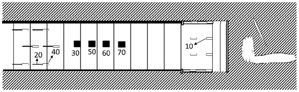
the device comprises an automatic excitation device 10, a two-dimensional fiber detector 20, a control platform 30, a data acquisition module 40, a portable detector 50, a communication module 60 and a data processing host 70.
The automatic excitation device is annularly arranged on a middle shield of the shield machine and used for beating a preformed hole of the middle shield;
the two-dimensional optical fiber detectors are arranged on the shield segment in the tunneling direction of the shield interval in the circumferential direction and used for detecting the beating signals;
and the data acquisition module is used for acquiring signals of the two-dimensional optical fiber detector, the acquired data signals are transmitted to the data processing host, and the data processing host determines the geological structure in front of the tunnel face and determines the position of the geological structure according to the received detection signals.
In the embodiment, referring to fig. 6, the excitation device of the automatic excitation device 10 includes a mounting seat 101, a sensor 102, a shock execution module 103, an air compressor 104, a dc power supply 105, a signal transmission and reception module 106, and a housing 107.
The sensor 102, the shock execution module 103, the air compressor 104, the direct current power supply 105 and the signal transmission and reception module 106 are all waterproof devices as shown in fig. 6.
The mounting seat 101 is connected with the housing 107 by bolts for later disassembly and replacement, and is padded with a rubber pad to ensure the waterproof performance of the shield machine. The mounting seat 101 and the shield machine shell are fixed in a welding mode.
The shock excitation execution module 103 is connected with the air compressor 104 in a welding mode, so that energy loss in the excitation process is reduced.
The shock excitation execution module 103 is responsible for knocking rock-soil bodies, and the air compressor 104 is responsible for providing knocking power.
The air compressor 104 is a multi-stage compressible machine that provides different percussive forces and frequencies for different rock masses.
The sensor 102 and the shock executing module 103 are not in contact before working, and in a moment of working, the sensor sends a signal to the signal transmitting and receiving module 106, the signal transmitting and receiving module 106 sends the signal to the control platform 30, and the control platform 30 controls the data acquisition module 40 to start acquisition.
The sensor 102 and the signal transmission and reception module 106 are connected by wire, so as to ensure the stability of data transmission.
Cushions are arranged among the air compressor 104, the direct current power supply 105 and the signal transmission and receiving module 106, so that the influence of vibration on the air compressor and the direct current power supply is reduced as much as possible.
The dc power supply 105 provides power to the sensor 102, the air compressor 104, and the signal transmission and reception module 106.
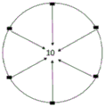
Specifically, the automatic excitation device is arranged in a shield of the shield machine, and the annular arrangement is 2 rings and 12 rings in total. Every 6 departments of ring, along the shield structure machine both sides evenly arranged, two interannular distances are 1m, and specific position refers to 2, so arrange and to guarantee when later stage data analysis, to the accurate location of place ahead calamity source position.
Specifically, the control platform 30 is the center of the whole detection system, and controls the working state and time of the automatic excitation device 10, the data acquisition module 40, the portable detector 50 and the data processing host 70.
The control platform 30 is placed in the driver's operating room or on both sides of the trolley, and the safety of the operator is ensured.
The communication module 60 is a medium for the control platform 30 to communicate with the automatic excitation device 10, the data acquisition module 40, the portable detector 50 and the data processing host 70, and adopts a wireless communication system.
Specifically, the data acquisition module 40 is responsible for acquiring waveform information detected by the two-dimensional fiber detector 20, the data acquisition module 40 transmits the data to the control platform 30, the control platform 30 transmits the data to the data processing host 70 for interpretation, and the result is transmitted to the control platform 30, so as to obtain geological conditions in front of shield construction, such as distribution, scale, crushing degree, structural characteristics and the like of strata lithology boundaries, boulders, karst (soil) holes, faults, fracture dense zones, crushing zones and the like.
The two-dimensional optical fiber geophone 20 is arranged on the outer side of the duct piece, and the waveform signal is transmitted to the data acquisition module 40 in a wired mode. See fig. 5.
According to the length of the shield segment, one to two reserved ports of the two-dimensional fiber detectors 20 are arranged on the inner side of the segment, so that the data acquisition modules 40 are connected.
After advance geological forecast is accomplished, the optic fibre in the two-dimensional fiber detector can exert the waste heat, and the deformation of section of jurisdiction is synchronous with the deformation of optic fibre, and the deformation condition of optic fibre can utilize existing wired line to spread this moment, is received by shield interval fortune dimension later stage equipment to monitoring section of jurisdiction warp.
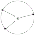
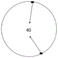
Specifically, referring to fig. 2, 3 and 4, five rings of two-dimensional fiber detectors are arranged on the shield pipe segment along the tunneling direction of the shield zone, and are arranged in a quincunx manner according to 3, 2, 3 and 2, and the specific position of the front poor geologic body can be determined by the receiving table net arrangement method, so that a quantitative prediction result is provided for construction.
Specifically, the portable detector 50 comprises a plurality of ordinary detectors, a coupling agent and a small telescopic rod, wherein the rod end of the telescopic rod is provided with the ordinary detectors, and the telescopic rod is used for feeding the ordinary detectors into the grouting holes; the ordinary detector is in close contact with the rock mass behind the pipe piece through the coupling agent, and after the ordinary detector is used, the ordinary detector is withdrawn. When the failure or malfunction of the two-dimensional optical fiber detector on the outer side of the shield segment is detected, the device is adopted.
The small telescopic rod is divided into a plurality of sections and adjustable in length. The middle of the first section and the second section at the front end is connected by adopting a ball capable of freely rotating, and the angle of the ball is adjustable, so that the ball can conveniently enter a grouting hole of a shield segment. The end part is provided with a common detector, and the tail part is provided with a triangular fixing device.
In another embodiment, an operation method based on the geological advanced forecasting system comprises the following steps:
step 1, the automatic excitation device at the shield position in the shield machine and the installation work of specific shield segments are well finished.
And 2, after the shield machine tunnels for a circle distance, the shield machine starts to install the duct pieces, and geological detection is started by using the gap. And opening the control platform, controlling the starting of the automatic excitation device, the data acquisition module and the data processing host, and simultaneously connecting the reserved port of the two-dimensional optical fiber detector with the data acquisition module. Starting the automatic excitation device, carrying out trial hammering and observing the waveform after hammering.
And 3, if the effect is good, knocking each hammering point three times in sequence, receiving waveform data transmitted by the two-dimensional optical fiber detector by using the data acquisition module, closing the automatic excitation device and the control platform, carrying out geological condition inversion, issuing a geological forecast report of the section, and finishing the forecast.
And 4, if the waveform cannot be received or is smaller, increasing the hammering force in an attempt, and checking whether the hammering force is insufficient due to stratum change or not, so that reasonable data cannot be received, if the hammering force can be solved after the hammering force is increased, performing step 3, if the hammering force can be solved, considering to replace the automatic excitation device, after replacement, continuing to perform trial hammering, observing the waveform, if the effect meets the inversion requirement, repeating the step 3, and otherwise, performing the step 5.
And 5, if the data cannot be received after the hammering force is added to the maximum value, considering whether the two-dimensional detector is damaged or not. If damage, under the unable circumstances of changing, adopt portable detector as reserve detector, utilize small-size telescopic link to send into the hoist and mount hole with the detector that scribbles the couplant to fixed small-size telescopic link tries the hammering once more, after effectual, repeats step 3.
The data acquisition module 40 is connected to the two-dimensional fiber detector 20 and is configured to acquire a signal of the two-dimensional fiber detector 20. The communication module 60 transmits the data signal collected by the data collecting module 40 to the data processing host 70, and the communication module 60 adopts a wireless communication module in consideration of the internal structure of the shield. The data processing host 70 performs geophysical inversion based on the received detection signals and on the signals obtained by the detection, thereby determining the geological structure (stratigraphic lithology boundaries, distribution, scale, fracture degree, structural characteristics of boulders, solution (soil) holes, faults, fracture dense zones, fracture zones, and the like) in front of the face and determining the position thereof.
The shield shell mechanical seismic source-specific segment receiving type unfavorable geological detection system and method carried on the shield machine provided by the embodiment of the invention. The two-dimensional optical fiber detector is pre-embedded in advance when the duct piece is prefabricated in a duct piece factory, and the construction quality is guaranteed. The test is carried out before the installation of the duct piece and before the work, if the two-dimensional optical fiber detector is found to be damaged, the portable detector is selected to replace the two-dimensional optical fiber detector, and the integrity of received data is guaranteed.
The operation time of the system is when the shield machine assembles the duct pieces;
when the automatic excitation device can not work normally, the automatic excitation device can be directly dismantled and replaced by a whole set of automatic excitation device.
The system adopts double insurance of the pre-embedded two-dimensional optical fiber detector and the portable detector, and ensures the integrity of data receiving.
The system and the method solve the difficult problem that the poor geologic body in front of the shield construction tunnel is difficult to forecast all the time, and mainly comprise the difficult problems of the judgment of the distribution, the scale, the crushing degree and the structural characteristics of stratum lithologic boundaries, boulders, karst (soil) holes, faults, fracture dense zones, crushing zones and the like. The method has the advantages that the adverse geological information in front of the shield construction can be rapidly and accurately obtained, and the influence of the external environment is basically avoided; meanwhile, by using the interval of assembling shield segments, the advantages of advanced geological forecast and equipment maintenance can be realized; under the condition that shield construction is not delayed, a large amount of geological advanced forecasting can be carried out, massive inversion results are obtained and verified mutually, the basis is provided for shield construction, forecasting can be carried out when unfavorable geology is met, and dangerous conditions are avoided, so that the construction progress and the construction safety are guaranteed.
The above description is only a preferred embodiment of the present invention and is not intended to limit the present invention, and various modifications and changes may be made by those skilled in the art. Any modification, equivalent replacement, or improvement made within the spirit and principle of the present invention should be included in the protection scope of the present invention.
Although the embodiments of the present invention have been described with reference to the accompanying drawings, it is not intended to limit the scope of the present invention, and it should be understood by those skilled in the art that various modifications and variations can be made without inventive efforts by those skilled in the art based on the technical solution of the present invention.