CN110723677B - Precast Beam Assisted Lifting Trolley - Google Patents
Precast Beam Assisted Lifting Trolley Download PDFInfo
- Publication number
- CN110723677B CN110723677B CN201911117543.0A CN201911117543A CN110723677B CN 110723677 B CN110723677 B CN 110723677B CN 201911117543 A CN201911117543 A CN 201911117543A CN 110723677 B CN110723677 B CN 110723677B
- Authority
- CN
- China
- Prior art keywords
- oil
- fixedly connected
- bottom plate
- power
- oil cylinder
- Prior art date
- Legal status (The legal status is an assumption and is not a legal conclusion. Google has not performed a legal analysis and makes no representation as to the accuracy of the status listed.)
- Active
Links
Images


Classifications
-
- B—PERFORMING OPERATIONS; TRANSPORTING
- B66—HOISTING; LIFTING; HAULING
- B66F—HOISTING, LIFTING, HAULING OR PUSHING, NOT OTHERWISE PROVIDED FOR, e.g. DEVICES WHICH APPLY A LIFTING OR PUSHING FORCE DIRECTLY TO THE SURFACE OF A LOAD
- B66F3/00—Devices, e.g. jacks, adapted for uninterrupted lifting of loads
- B66F3/46—Combinations of several jacks with means for interrelating lifting or lowering movements
-
- B—PERFORMING OPERATIONS; TRANSPORTING
- B66—HOISTING; LIFTING; HAULING
- B66F—HOISTING, LIFTING, HAULING OR PUSHING, NOT OTHERWISE PROVIDED FOR, e.g. DEVICES WHICH APPLY A LIFTING OR PUSHING FORCE DIRECTLY TO THE SURFACE OF A LOAD
- B66F3/00—Devices, e.g. jacks, adapted for uninterrupted lifting of loads
- B66F3/24—Devices, e.g. jacks, adapted for uninterrupted lifting of loads fluid-pressure operated
- B66F3/25—Constructional features
-
- E—FIXED CONSTRUCTIONS
- E01—CONSTRUCTION OF ROADS, RAILWAYS, OR BRIDGES
- E01D—CONSTRUCTION OF BRIDGES, ELEVATED ROADWAYS OR VIADUCTS; ASSEMBLY OF BRIDGES
- E01D21/00—Methods or apparatus specially adapted for erecting or assembling bridges
-
- F—MECHANICAL ENGINEERING; LIGHTING; HEATING; WEAPONS; BLASTING
- F15—FLUID-PRESSURE ACTUATORS; HYDRAULICS OR PNEUMATICS IN GENERAL
- F15B—SYSTEMS ACTING BY MEANS OF FLUIDS IN GENERAL; FLUID-PRESSURE ACTUATORS, e.g. SERVOMOTORS; DETAILS OF FLUID-PRESSURE SYSTEMS, NOT OTHERWISE PROVIDED FOR
- F15B13/00—Details of servomotor systems ; Valves for servomotor systems
- F15B13/02—Fluid distribution or supply devices characterised by their adaptation to the control of servomotors
- F15B13/04—Fluid distribution or supply devices characterised by their adaptation to the control of servomotors for use with a single servomotor
- F15B13/044—Fluid distribution or supply devices characterised by their adaptation to the control of servomotors for use with a single servomotor operated by electrically-controlled means, e.g. solenoids, torque-motors
- F15B2013/0448—Actuation by solenoid and permanent magnet
Landscapes
- Engineering & Computer Science (AREA)
- Structural Engineering (AREA)
- Life Sciences & Earth Sciences (AREA)
- Geology (AREA)
- Mechanical Engineering (AREA)
- Architecture (AREA)
- Civil Engineering (AREA)
- Conveying And Assembling Of Building Elements In Situ (AREA)
Abstract
本发明涉及预制梁辅助举升小车,有效的解决了现有施工方式中千斤顶举升拼装预制梁效率低下、现有小车带动预制梁移动时需要破坏膺架、现有小车不便于控制的问题;其解决的技术方案是包括小车的底板,所述的底板左右两侧均固定连接有动力装置,所述的底板上固定连接有中板,所述的中板上转动连接有顶板,所述的上板上设置有两组举升装置,两组所述的举升装置均和固定连接在顶板上的顶板油泵连通;本发明结构简洁,便于操控,可有效的提高预制梁拼装的效率,同时可保证膺架的完整,便于周转利用,实用性强。

The invention relates to a prefabricated beam auxiliary lifting trolley, which effectively solves the problems of low efficiency in the prior construction method of jack-lifting and assembling the prefabricated beam, the existing trolley needs to destroy the scaffold when driving the prefabricated beam to move, and the existing trolley is inconvenient to control; The technical solution is to include a bottom plate of the trolley, the left and right sides of the bottom plate are fixedly connected with power devices, the bottom plate is fixedly connected with a middle plate, the middle plate is rotatably connected with a top plate, and the Two sets of lifting devices are arranged on the upper plate, and the two sets of lifting devices are connected with the top plate oil pump fixedly connected to the top plate; the present invention has a simple structure, is easy to operate, can effectively improve the efficiency of prefabricated beam assembling, and at the same time It can ensure the completeness of the dummy frame, is convenient for turnover and has strong practicability.
Description
技术领域technical field
本发明涉及桥梁施工机械技术领域,具体是预制梁辅助举升小车。The invention relates to the technical field of bridge construction machinery, in particular to a prefabricated beam auxiliary lifting trolley.
背景技术Background technique
随着过架桥技术的逐渐发展和日益成熟,越来越多的桥梁架设采用预制节段梁手法,箱梁提前在工厂预制,并分节分段运输至施工现场,之后在施工时现场吊装、定位、拼装。其中,节段箱梁采用膺架进行拼装架设。膺架主梁多为两跨简支梁结构,纵向主梁采用多层六四式军用梁。每段箱梁底部平衡对称设置4个螺旋支撑,螺旋支撑支放在膺架纵横分配梁顶层横梁之上。With the gradual development and maturity of bridge bridge technology, more and more bridges are erected using prefabricated segment beams. The box beams are prefabricated in the factory in advance, and transported to the construction site in sections and sections, and then hoisted on site during construction. , positioning and assembly. Among them, the segmental box girder is assembled and erected by the artificial frame. The main beam of the artificial frame is mostly a two-span simply supported beam structure, and the longitudinal main beam adopts the multi-layer six-four type military beam. Four spiral supports are arranged symmetrically at the bottom of each box girder, and the spiral supports are supported on the top beam of the vertical and horizontal distribution beams of the scaffold.
而移梁时则采用龙门吊运方案,节段箱梁利用吊杆穿在箱梁端部的预留孔内进行吊装。箱梁节段强度达到规定强度后,用龙门进行提升移运到存梁区。梁段架设前,从存梁区将梁体吊装至运梁平车上,并从运梁平车上吊运至膺架上。When moving the beam, the gantry hoisting scheme is adopted, and the segmented box beam is hoisted by passing through the reserved hole at the end of the box beam with the boom. After the strength of the box girder segment reaches the specified strength, use the gantry to lift and move it to the beam storage area. Before the beam section is erected, the beam body is hoisted from the beam storage area to the beam transporting flat car, and then hoisted from the beam transporting flat car to the scaffold.
节段箱梁架设到端头节时,需进行架设前的支座安装,为架梁做好准备。支座安装前应认真检查桥墩和垫石顶面标高。支座按照设计标高调整到位后,采用水泥浆进行灌浆处理,支座安装后顶、底面应与梁、垫石砼面之间无间隙,并保证支座水平。When the section box girder is erected to the end section, it is necessary to install the supports before erection to prepare for the erection of the girder. Before the installation of the bearing, the elevation of the pier and the top surface of the pad should be carefully checked. After the support is adjusted in place according to the design elevation, use cement grout for grouting. After the support is installed, there should be no gap between the top and bottom surfaces of the beam and the concrete surface of the cushion, and the support should be level.
之后则是节段梁的精确调位,精确调位是指将梁段横向、纵向和竖向三个方向均调整到设计要求的位置。纵、横、竖向利用双坐标千斤顶调节,以线路的中心线为基准,即:线路中心线和梁体中心线重合,其余梁段以梁端相对距离控制调整;高度方向按照施工预设拱度设定和逐次调整。具体的,每一梁段均放在四个螺旋支撑或千斤顶上,并且每一个支撑点都有三个自由度,这三个自由度相互制约,调整其中一个必将影响其余两个。所以梁段精确调位是一个反复调整、逐步趋近的过程。施工中按照先纵向调整→横向调整→竖向调整的次序反复循环调整过程,直至达到设计要求。Then there is the precise adjustment of the segment beam, which refers to the adjustment of the horizontal, vertical and vertical directions of the beam segment to the position required by the design. The vertical, horizontal and vertical directions are adjusted by double-coordinate jacks, based on the center line of the line, that is, the center line of the line and the center line of the beam body are coincident, and the remaining beam sections are controlled and adjusted by the relative distance of the beam ends; the height direction is based on the construction preset arch degree setting and successive adjustment. Specifically, each beam segment is placed on four screw supports or jacks, and each support point has three degrees of freedom, these three degrees of freedom restrict each other, and adjusting one of them will definitely affect the other two. Therefore, the precise adjustment of the beam segment is a process of repeated adjustment and gradual approach. During construction, repeat the cycle adjustment process in the order of vertical adjustment→horizontal adjustment→vertical adjustment until the design requirements are met.
而四个螺旋支撑或千斤顶不能同时移动,行程短,效率底,每榀梁下都要四个千斤顶,费用高,最重要是移动速度太慢,端面涂抹的胶水还没移动到位就初凝了。The four screw supports or jacks cannot move at the same time, the stroke is short, and the efficiency is low. Four jacks are required under each beam, which is expensive. The most important thing is that the moving speed is too slow. .
现有的某些施工单位则在研制和尝试采用举升小车辅助拼装,然而申请人发现现行研制和试用的小车仍存在一些弊端,其中最严重的在于小车带动预制梁移动过程中的动力。现行研制和试用的小车的动力多采用液压顶推,其一端的固定方式多采用螺栓固定在膺架上,而这则需要在膺架上打若干的孔,这样该膺架在拆卸后很难再次使用,打孔成本太高且会产生大量的建筑废料,不利于绿色施工和成本控制,同时每次拆卸和安装液压顶推装置同样需要耗费很多工时,其虽比千斤顶便捷,但效率提升有限。故急需一种具有可活动固定的液压顶推装置、便于控制、节省工时和工人的举升小车。Some existing construction units are developing and trying to use lifting trolleys to assist in assembly. However, the applicant has found that the currently developed and tested trolleys still have some drawbacks, the most serious of which is the power of the trolley to drive the prefabricated beam to move. The power of the trolleys currently developed and tested is mostly hydraulic jacking, and the fixing method of one end is mostly fixed on the artificial frame by bolts, and this requires a number of holes in the artificial frame, so that the artificial frame is difficult to be disassembled. Re-use, the drilling cost is too high and a large amount of construction waste will be generated, which is not conducive to green construction and cost control. At the same time, it also takes a lot of man-hours to disassemble and install the hydraulic jacking device each time. Although it is more convenient than the jack, the efficiency improvement is limited. . Therefore, there is an urgent need for a lifting trolley with a movable and fixed hydraulic jacking device, which is easy to control and saves man-hours and workers.
因此,本发明提供一种预制梁辅助举升小车来解决此问题。Therefore, the present invention provides a prefabricated beam-assisted lifting trolley to solve this problem.
发明内容SUMMARY OF THE INVENTION
针对上述情况,为克服现有技术之缺陷,本发明提供一种预制梁辅助举升小车,有效的解决了现有施工方式中千斤顶举升拼装预制梁效率低下、现有小车带动预制梁移动时需要破坏膺架、现有小车不便于控制的问题。In view of the above situation, in order to overcome the defects of the prior art, the present invention provides a prefabricated beam auxiliary lifting trolley, which effectively solves the problem of the low efficiency of jack-lifting and assembling the prefabricated beam in the existing construction method, and when the existing trolley drives the prefabricated beam to move It is necessary to destroy the scaffolding, and the existing trolley is not easy to control.
本发明包括小车的底板,所述的底板左右两侧均固定连接有动力装置,所述的底板上固定连接有中板,所述的中板上转动连接有顶板,所述的顶板上设置有两组举升装置,两组所述的举升装置均和固定连接在顶板上的顶板油泵连通;The present invention includes the bottom plate of the trolley, the left and right sides of the bottom plate are fixedly connected with power devices, the bottom plate is fixedly connected with a middle plate, the middle plate is rotatably connected with a top plate, and the top plate is provided with a Two sets of lifting devices, both of which are in communication with the top plate oil pump fixedly connected to the top plate;
两组所述的举升装置均包括两个滑动连接在顶板上的垂直油缸和一个固定连接在顶板上的水平油缸,所述的水平油缸为双出杆油缸且水平油缸两端分别和两个垂直油缸固定连接;The two sets of lifting devices both include two vertical oil cylinders slidably connected to the top plate and one horizontal oil cylinder fixedly connected to the top plate. Vertical oil cylinder fixed connection;
两个所述的动力装置均包括一端固定连接在底板上的动力油缸,两个所述的动力油缸另一端均固定连接有动力梁,两个所述的动力梁两侧均固定连接有固定油缸,两个所述的动力油缸、四个所述的固定油缸均和固定连接在底板上的底板油泵连通,所述的底板上固定连接有油箱,所述的顶板油泵和底板油泵均和油箱连通。Both of the two power devices include a power cylinder whose one end is fixedly connected to the bottom plate, a power beam is fixedly connected to the other end of the two power cylinders, and a fixed cylinder is fixedly connected to both sides of the two power beams. , the two described power oil cylinders and the four described fixed oil cylinders are all communicated with the bottom plate oil pump that is fixedly connected to the bottom plate, the bottom plate is fixedly connected with an oil tank, and the top plate oil pump and the bottom plate oil pump are both communicated with the oil tank .
优选的,所述的顶板油泵和两个水平油缸连通的管道处均设置有水平电磁阀,所述的顶板油泵和四个所述的垂直油缸连通的管道处均设置有垂直电磁阀;Preferably, a horizontal solenoid valve is provided at the pipes communicating with the top plate oil pump and the two horizontal oil cylinders, and a vertical solenoid valve is provided at the pipes communicating with the top plate oil pump and the four vertical oil cylinders;
所述的底板油泵和两个所述的动力油缸连通的管道处均设置有动力电磁阀;A power solenoid valve is arranged at the pipe connecting the bottom plate oil pump and the two power oil cylinders;
两个所述的动力梁均为中空梁且均和相应的固定油缸、动力油缸连通,所述的动力梁和相应的固定油缸连通处均设置有固定电磁阀;The two power beams are both hollow beams and communicate with corresponding fixed oil cylinders and power oil cylinders, and fixed electromagnetic valves are provided at the communication places between the power beams and the corresponding fixed oil cylinders;
所述的顶板油泵、底板油泵、水平电磁阀、动力电磁阀、固定电磁阀均和固定连接在底板上的中控模块电连接。The top plate oil pump, the bottom plate oil pump, the horizontal electromagnetic valve, the power electromagnetic valve, and the fixed electromagnetic valve are all electrically connected to the central control module fixedly connected to the bottom plate.
优选的,所述的中板两侧分别固定连接有两个侧梁,四个所述的侧梁上均上下滑动连接有支撑座,四个所述的支撑座内均可拆卸连接有支撑螺杆,四个所述的支撑座一侧均滑动连接有转动连接在相应侧梁上的平衡杆,所述的平衡杆另一端滑动滑动连接有上下滑动连接在相应侧梁上的平衡平台,四个所述的平衡平台均通过弹簧和相应的侧梁相连,四个所述的平衡平台下端均固定连接有牛眼滚轮。Preferably, two side beams are fixedly connected on both sides of the middle plate respectively, and support seats are slidably connected up and down on the four side beams, and support screws can be detachably connected to the four support seats. One side of each of the support bases is slidably connected with a balance rod that is rotatably connected to the corresponding side beam, and the other end of the balance rod is slidably connected to a balance platform that is slidably connected to the corresponding side beam. The balance platforms are all connected with the corresponding side beams through springs, and the lower ends of the four balance platforms are fixedly connected with bulls-eye rollers.
优选的,所述的中板两侧均固定连接有矫正油缸,两个所述的矫正油缸上端均固定连接有弧形板;Preferably, straightening oil cylinders are fixedly connected to both sides of the middle plate, and arc plates are fixedly connected to the upper ends of the two straightening oil cylinders;
两个所述的矫正油缸均通过管道和底板油泵连通,两个所述的矫正油缸和底板油泵连通的管道处均设置有矫正电磁阀,所述的矫正电磁阀和所述的中控模块电连接。The two straightening oil cylinders are connected with the bottom plate oil pump through pipelines, and the two straightening oil cylinders and the bottom plate oil pump are connected with a straightening solenoid valve, and the straightening solenoid valve and the central control module electric connect.
优选的,两个所述的弧形板上面均转动连接有若干矫正钢球。Preferably, several straightening steel balls are rotatably connected to the two arc-shaped plates.
优选的,四个所述的垂直油缸下端均固定连接有牛眼滚轮。Preferably, bulls-eye rollers are fixedly connected to the lower ends of the four vertical oil cylinders.
优选的,四个所述的固定油缸下端均转动连接有轮子。Preferably, wheels are rotatably connected to the lower ends of the four fixed oil cylinders.
优选的,所述的中板上固定连接有回转油缸,所述的回转油缸上端固定连接有顶板,所述的回转油缸和所述的油箱连通。Preferably, a rotary oil cylinder is fixedly connected to the middle plate, a top plate is fixedly connected to the upper end of the rotary oil cylinder, and the rotary oil cylinder is communicated with the oil tank.
优选的,所述的中控模块包括电磁阀控制单元、信号处理单元、无线信号收发单元。Preferably, the central control module includes a solenoid valve control unit, a signal processing unit, and a wireless signal transceiver unit.
优选的,所述的预制梁辅助举升小车两个为一组,两个所述预制梁辅助举升小车的中控模块通过无线连接有外接遥控装置。Preferably, two of the prefabricated beam auxiliary lifting trolleys are in a group, and the central control modules of the two prefabricated beam auxiliary lifting trolleys are wirelessly connected with an external remote control device.
优选的,所述的底板下端转动连接有若干辅助轮。Preferably, a plurality of auxiliary wheels are rotatably connected to the lower end of the bottom plate.
本发明针对现有施工方式中千斤顶举升拼装预制梁效率低下、现有小车带动预制梁移动时需要破坏膺架、现有小车不便于控制的问题做出改进,具有以下有益效果:The present invention makes improvements to the problems in the existing construction method that the jack lifts and assembles the prefabricated beams, the existing trolley needs to destroy the scaffold when driving the prefabricated beams to move, and the existing trolley is inconvenient to control, and has the following beneficial effects:
1、采用举升小车代替千斤顶,使得举升拼装预制梁时能带动预制梁移动更大的距离,从而提高了拼装效率;1. The lifting trolley is used instead of the jack, so that when the prefabricated beam is lifted and assembled, it can drive the prefabricated beam to move a larger distance, thereby improving the assembly efficiency;
2、采用两组动力梁和固定油缸的组合取代现有小车行进需要螺栓固定液压顶推装置的结构,节省了将液压顶推装置固定在膺架上的拆装过程,极大的节省了工时,同时保护了膺架,使得膺架可周转使用,节省了施工成本,实现了绿色施工;2. The combination of two sets of power beams and fixed oil cylinders is used to replace the structure of the existing trolley that requires bolts to fix the hydraulic jacking device, which saves the disassembly and assembly process of fixing the hydraulic jacking device on the artificial frame and greatly saves man-hours. At the same time, it protects the scaffolding, so that the scaffolding can be used in turnaround, saving construction costs and realizing green construction;
3、采用中控模块和遥控装置控制本发明中各个电磁阀和油泵的工作状态,从而更便于工人控制预制梁的拼装。3. The central control module and the remote control device are used to control the working states of each solenoid valve and oil pump in the present invention, so that it is more convenient for workers to control the assembly of the prefabricated beams.
本发明结构简洁,便于操控,可有效的提高预制梁拼装的效率,同时可保证膺架的完整,便于周转利用,实用性强。The invention has a simple structure, is easy to operate, can effectively improve the efficiency of prefabricated beam assembling, can ensure the integrity of the artificial frame, is convenient for turnover and has strong practicability.
附图说明Description of drawings
图1为本发明立体示意图一。FIG. 1 is a perspective schematic diagram 1 of the present invention.
图2为本发明左视示意图。FIG. 2 is a schematic left side view of the present invention.
图3为本发明去膺架模型主视示意图。FIG. 3 is a schematic front view of the model of the present invention for removing the dummy frame.
图4为本发明垂直油缸及其相关结构剖视示意图一。FIG. 4 is a schematic
图5为本发明动力梁及其相关结构局部立体剖视示意图。FIG. 5 is a schematic partial three-dimensional cross-sectional view of the dynamic beam and its related structures of the present invention.
图6为本发明动力梁及其相关结构剖视示意图。6 is a schematic cross-sectional view of the power beam and its related structures of the present invention.
图7为本发明侧梁及其相关结构局部剖视示意图。FIG. 7 is a schematic partial cross-sectional view of a side beam and its related structures of the present invention.
图8为本发明立体示意图二。FIG. 8 is a second perspective view of the present invention.
图9为本发明各个电磁阀工作状态。Fig. 9 is the working state of each solenoid valve of the present invention.
具体实施方式Detailed ways
有关本发明的前述及其他技术内容、特点与功效,在以下配合参考附图1至图9对实施例的详细说明中,将可清楚的呈现。以下实施例中所提到的结构内容,均是以说明书附图为参考。The foregoing and other technical contents, features and effects of the present invention will be clearly presented in the following detailed description of the embodiments with reference to FIGS. 1 to 9 . The structural contents mentioned in the following embodiments are all referenced to the accompanying drawings.
下面将参照附图描述本发明的各示例性的实施例。Exemplary embodiments of the present invention will be described below with reference to the accompanying drawings.
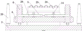
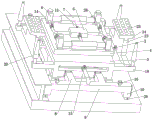
实施例一,本发明为预制梁辅助举升小车,其特征在于,包括小车的底板1,所述的底板1下端转动连接有行走轮,在工作时,底板1依靠行走轮在膺架上行进,底板1同时为本装置的基础,为后续结构提供固定基础,所述的底板1左右两侧均固定连接有动力装置,所述的动力装置用于推动底板1在膺架上行走,所述的底板1上固定连接有中板3,所述的中板3上转动连接有顶板4,底板1、中板3、顶板4构成本装置的承载基础结构,同时为后续各个结构提供固定基础,所述的顶板4上设置有两组举升装置,两组所述的举升装置均和固定连接在顶板4上的顶板油泵5连通,所述的顶板油泵5和外界电源相连,为便于本装置行走,提高灵活性,在底板1上固定连接有柴油发电机和配套的柴油箱12,顶板油泵5和柴油发电机相连并由柴油发电机供电;
两组所述的举升装置均包括两个滑动连接在顶板4上的垂直油缸6和一个固定连接在顶板4上的水平油缸7,所述的水平油缸7为双出杆油缸且水平油缸7两端分别和两个垂直油缸6固定连接,两组共四个垂直油缸6用于举升和承载预制梁,在垂直油缸6上端固定连接有橡胶厚垫片,从而防止预制梁梁体在和垂直油缸6接触时造成的碰撞损伤,所述的水平油缸7用于调节相连的两个垂直油缸6的相对位置,从而使得本装置可使用宽度不同的各种预制梁梁体,具体的,所述的水平油缸7为双出轴油缸,也称为双向油缸,向其内部充油或抽油可带动其两个轴同步伸出或收回,从而实现对相连的两个垂直油缸6的同步调节;The two groups of lifting devices include two
两个所述的动力装置均包括一端固定连接在底板1上的动力油缸8,两个所述的动力油缸8另一端均固定连接有动力梁9,两个所述的动力梁9两侧均固定连接有固定油缸10,每个动力梁9两端的固定油缸10均位于相应膺架工字钢的上下两翼板之间,动力梁9两端的固定油缸10伸出时,可将动力梁9卡紧在膺架上,从而使得动力梁9可作为动力油缸8的发力基础,便于动力油缸8以动力梁9为基础推动底板1在膺架上运动,为保证受力的平衡,每个动力梁9上对称的固定连接有两个另一端固定连接在底板1上的动力油缸8,即底板1两侧对称的固定连接有四个动力油缸8,两个所述的动力油缸8、四个所述的固定油缸10均和固定连接在底板1上的底板油泵11连通,所述的底板油泵11和柴油发电机电连接,所述的底板1上固定连接有油箱12,所述的顶板油泵5和底板油泵11均和油箱12通过软管28连通;Both of the two described power devices include a
当四个垂直油缸6承载梁体时,本装置称重较重,为分散对膺架的压力,也为了保护小车,所述的底板1下端转动连接有若干辅助轮,从而增大本装置和膺架的接触面积,保护行走轮和膺架;When the four
本实施例在具体使用时,用户先将小车放置在膺架上并预先通过顶板油泵5通过水平油缸7调节相连的两个垂直油缸6之间的距离,之后通过龙门吊或吊机将梁体放置在预先放置好的支撑螺杆20上,之后控制小车行走到所需的位置,具体的,可控制底板油泵11先向左侧的固定油缸10充油,从而将左侧的动力梁9压紧在膺架上,之后保持油压并向左右两侧的四个动力油缸8内充油,左侧的动力油缸8伸出并推动底板1在膺架上向右运动,同时右侧的动力油缸8也伸出,当左侧的动力油缸8伸出至最远位置时,右侧的固定油缸10伸出将右侧的动力梁9压紧在膺架上,同时左侧的固定油缸10收回,使左侧的动力梁9变为活动状态,之后底板油泵11同时向四个动力油泵抽油,右侧的动力油缸8带动底板1小车继续向右行走,以此实现小车的行走,若小车要向左行走则反向操作即可,当小车来到需要的位置后,通过顶板油泵5控制垂直油缸6升起将梁体举升,之后再控制小车行走将梁体和前一榀梁体拼合。In the specific use of this embodiment, the user first places the trolley on the scaffold and adjusts the distance between the two connected
实施例二,在实施例一的基础上,所述的顶板油泵5和两个水平油缸7连通的管道处均设置有水平电磁阀13,所述的顶板油泵5和四个所述的垂直油缸6连通的管道处均设置有垂直电磁阀14,即当需要垂直油缸6工作时,两个水平电磁阀13关闭,四个垂直电磁阀14开启,当需要水平油缸7工作时,两个水平电磁阀13开启,四个垂直电磁阀14关闭;
所述的底板油泵11和两个所述的动力油缸8连通的管道处均设置有动力电磁阀15,两个所述的动力梁9均为中空梁且均和相应的固定油缸10、动力油缸8连通,所述的动力梁9和相应的固定油缸10连通处均设置有固定电磁阀16,即当需要固定电磁阀16工作时,动力电磁阀15打开,液压油先将动力梁9充满,之后液压油充入固定油缸10并使固定油缸10伸出,当固定油缸10伸出后,控制固定电磁阀16关闭,此时即保证了固定油缸10内的油压,从而保证固定油缸10可将动力梁9固定在膺架上,之后,底板油泵11继续向动力梁9内充油并通过动力油缸8推动小车运动;The said bottom
所述的顶板油泵5、底板油泵11、水平电磁阀13、动力电磁阀15、固定电磁阀16均和固定连接在底板1上的中控模块17电连接,本实施例在具体使用时,当用户需要小车运动时,控制底板油泵11工作,底板油泵11向动力梁9充油,液压油将动力梁9充满,并充入固定油缸10使固定油缸10伸出,当固定油缸10伸出后,固定电磁阀16关闭,底板油泵11继续向动力梁9内充油并通过动力油缸8推动小车运动,因固定油缸10大小恒定,故每次将固定油缸10充满并使固定油缸10伸出将动力梁9卡紧的时间均相同,故固定电磁阀16为常闭的延时关闭阀门,即固定电磁阀16常闭,当开启固定电磁阀16时间达到预设值时,固定电磁阀16自动关闭;The top
当需要垂直油缸6工作时,两个水平电磁阀13关闭,四个垂直电磁阀14开启,顶板油泵5向垂直油缸6充油或抽油并使得垂直油缸6伸出或收缩,当需要水平油缸7工作时,两个水平电磁阀13开启,四个垂直电磁阀14关闭,顶板油泵5向水平油缸7内充油或抽油并使得水平油缸7伸出或收缩。When the
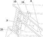
实施例三,在实施例二的基础上,为进一步提高本装置的便捷性,本实施例提供一种具体结构,使得本装置自带支撑螺杆20并在不需要时使支撑螺杆20和膺架脱离接触从而不影响本装置行走,具体的,所述的中板3两侧分别固定连接有两个侧梁18,四个侧梁18的高度均高于膺架工字钢上端翼板的上端面,四个所述的侧梁18上均上下滑动连接有支撑座19,四个所述的支撑座19内均可拆卸连接有支撑螺杆20,支撑螺杆20下压可使得支撑螺杆20下端面和工字钢上端翼板的上端面接触,同时支撑螺杆20下压可带动支撑座19同步向下运动,四个所述的支撑座19一侧均滑动连接有转动连接在相应侧梁18上的平衡杆21,所述的平衡杆21另一端滑动滑动连接有上下滑动连接在相应侧梁18上的平衡平台22,四个所述的平衡平台22均通过弹簧和相应的侧梁18相连,当梁体放置在支撑螺杆20上时,支撑螺杆20受力下压,其下端和膺架工字钢接触并以此将梁体支撑,支撑螺杆20下压带动支撑座19向下运动,在平衡杆21的作用下,平衡平台22被抬起并压缩弹簧,当梁体被垂直油缸6托起时,在弹簧的作用下,平衡平台22下压,支撑座19在平衡杆21的作用下被抬起,支撑螺杆20和膺架工字钢脱离接触,不影响小车行走,四个所述的平衡平台22下端均固定连接有牛眼滚轮,牛眼滚轮的设置可使得侧梁18更好的在膺架工字钢上行走,本实施例在具体使用时,当梁体放置在支撑螺杆20上时,支撑螺杆20受力下压,其下端和膺架工字钢接触并以此将梁体支撑,支撑螺杆20下压带动支撑座19向下运动,在平衡杆21的作用下,平衡平台22被抬起并压缩弹簧,牛眼滚轮和膺架工字钢脱离接触,当梁体被垂直油缸6托起时,在弹簧的作用下,平衡平台22下压,牛眼滚轮和膺架工字钢接触,支撑座19在平衡杆21的作用下被抬起,支撑螺杆20和膺架工字钢脱离接触,便于小车行走,需注意的是,支撑螺杆20上端面高度高于垂直油缸6收缩时上端面的高度。
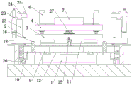
实施例四,在实施例一的基础上,因龙门吊或吊机在吊运梁体过程中很难保证梁体不摆动而摆正放置在支撑螺柱上,为保证梁体在龙门吊或吊机放置在支撑螺柱上时不偏斜,本实施例提供一种具体的结构,具体的,所述的中板3两侧均固定连接有矫正油缸23,两个所述的矫正油缸23上端均固定连接有弧形板24,两个弧形板24半径、圆心角均相同,两个所述的弧形板24上面均转动连接有若干矫正钢球25,当梁体下放时,先将矫正油缸23升起,梁体下端面接触弧形板24和其上的矫正钢球25,梁体下端面沿着矫正钢球25滑动,两个相对的弧形板24及其上的矫正钢球25导向梁体下端弧形面摆正,在弧形板24上的矫正钢球25的作用下,梁体轴心线和弧形板24的轴心线共面且该面垂直于水平面;
两个所述的矫正油缸23均通过管道和底板油泵11连通,两个所述的矫正油缸23和底板油泵11连通的管道处均设置有矫正电磁阀2,所述的矫正电磁阀2和所述的中控模块17电连接,本实施例在具体使用时,当梁体放置在支撑螺杆20之前,先控制矫正电磁阀2开启,动力电磁阀15关闭,底板油泵11工作将矫正油缸23升起,之后龙门吊或吊机将梁体放下,梁体下端面接触弧形板24,在弧形板24上的矫正钢球25的作用下,梁体被摆正,之后收缩矫正油缸23,将梁体放置在支撑螺杆20上,为防止梁体在摆正过程中对矫正油缸23造成损坏,在矫正油缸23伸出到最高点后,控制矫正电磁阀2略微关闭,使矫正油缸23和底板油泵11连通的管道管径变小,再配合粘稠的液压油,形成临时的阻尼器,缓冲梁体下落对矫正油缸23的冲击,需注意的是,因吊装过程中,即便梁体会出现偏移,其偏移角度也必然较小,故本实施例仅起到对梁体偏移的终端微调,故弧形板24和矫正钢球25足以实现对梁体偏移的微调。The two described straightening
实施例五,在实施例二的基础上,四个所述的垂直油缸6下端均固定连接有牛眼滚轮,牛眼滚轮的设置便于垂直油缸6在顶板4上运动,同时,在垂直油缸6承载梁体时,牛眼滚轮也能更好的为垂直油缸6提供支撑。
实施例六,在实施例二的基础上,四个所述的固定油缸10下端均转动连接有轮子26,轮子26的设置使的底板1在移动并带动动力梁9移动时,动力梁9能更好的在膺架上移动。
实施例七,在实施例一的基础上,所述的中板3上固定连接有回转油缸27,所述的回转油缸27上端固定连接有顶板4,所述的回转油缸27和所述的油箱12连通,所述的回转油缸27和柴油发电机电连接,所述的回转油缸27的设置使得顶板4的转动可控,在垂直油缸6承载梁体后,回转油缸27可带动顶板4转动,进而带动梁体转动,从而实现梁体的微调,该设置主要用于在矫正油缸23失效时保证本装置仍然能将梁体和前一榀梁体对接。
实施例八,在实施例二的基础上,所述的中控模块17包括电磁阀控制单元、信号处理单元、无线信号收发单元,所述的电磁阀控制单元和所述的水平电磁阀13、垂直电磁阀14、动力电磁阀15、固定电磁阀16、矫正电磁阀2均电连接并可控制各个电磁阀的启闭,所述的无线信号收发单元可通过无线信号和无线遥控装置相连,使得用户可通过无线遥控装置控制本装置的工作,信号处理单元用于处理无线信号收发单元接受的信号并将受到的信号处理后通过电磁阀控制单元控制各个电磁阀的启闭。
实施例九,在实施例一到八任一的基础上,所述的预制梁辅助举升小车两个为一组,两个所述预制梁辅助举升小车的中控模块17通过无线连接有外接遥控装置,本实施例的设置在于提高本装置的稳定性,两个小车分别放置于梁体两端,便于更好的更稳定的承托和拼合梁体,同时,两个小车同步工作也使得矫正油缸23在矫正梁体的时候能更好的矫正,即若梁体在下放过程中向一侧偏斜,则梁体下端面在接触矫正油缸23时,其接触的是两个小车相对侧的矫正油缸23,从而在弧形板24和矫正钢球25的作用下,梁体下端面向弧形板24中部微小距离的滑移,从而更好的起到矫正作用。In the ninth embodiment, on the basis of any one of the first to eighth embodiments, two of the prefabricated beam auxiliary lifting trolleys are in a group, and the
本发明在具体使用时,用户先控制本装置到需要的位置,具体的,控制底板油泵11工作,底板油泵11向动力梁9充油,液压油将动力梁9充满,并充入固定油缸10使固定油缸10伸出,当固定油缸10伸出后,固定电磁阀16关闭,底板油泵11继续向动力梁9内充油并通过动力油缸8推动小车运动,因固定油缸10大小恒定,故每次将固定油缸10充满并使固定油缸10伸出将动力梁9卡紧的时间均相同,故固定电磁阀16为常闭的延时关闭阀门,即固定电磁阀16常闭,当开启固定电磁阀16时间达到预设值时,固定电磁阀16自动关闭;In the specific use of the present invention, the user first controls the device to the required position, specifically, controls the bottom
在调节垂直油缸6之间的距离,具体的,控制两个水平电磁阀13开启,四个垂直电磁阀14关闭,顶板油泵5向水平油缸7内充油或抽油并使得水平油缸7伸出或收缩;In adjusting the distance between the
之后,控制矫正电磁阀2开启,动力电磁阀15关闭,底板油泵11工作将矫正油缸23升起,之后,控制矫正电磁阀2略微关闭,之后龙门吊或吊机将梁体放下,梁体下端面接触弧形板24,在弧形板24上的矫正钢球25的作用下,梁体被摆正,略微关闭的矫正电磁阀2使得矫正油缸23和底板油泵11连通的管道管径变小,再配合粘稠的液压油,形成临时的阻尼器,缓冲梁体下落对矫正油缸23的冲击;After that, control the
之后控制垂直油缸6工作,具体的,控制两个水平电磁阀13关闭,四个垂直电磁阀14开启,顶板油泵5向垂直油缸6充油或抽油并使得垂直油缸6伸出或收缩;Then control the
当梁体放置在支撑螺杆20上时,支撑螺杆20受力下压,其下端和膺架工字钢接触并以此将梁体支撑,支撑螺杆20下压带动支撑座19向下运动,在平衡杆21的作用下,平衡平台22被抬起并压缩弹簧,牛眼滚轮和膺架工字钢脱离接触,当梁体被垂直油缸6托起时,在弹簧的作用下,平衡平台22下压,牛眼滚轮和膺架工字钢接触,支撑座19在平衡杆21的作用下被抬起,支撑螺杆20和膺架工字钢脱离接触,便于小车行走,之后控制小车行走将梁体和前一榀梁对接即可。When the beam body is placed on the
本发明针对现有施工方式中千斤顶举升拼装预制梁效率低下、现有小车带动预制梁移动时需要破坏膺架、现有小车不便于控制的问题做出改进,具有以下有益效果:The present invention makes improvements to the problems in the existing construction method that the jack lifts and assembles the prefabricated beams, the existing trolley needs to destroy the scaffold when driving the prefabricated beams to move, and the existing trolley is inconvenient to control, and has the following beneficial effects:
1、采用举升小车代替千斤顶,使得举升拼装预制梁时能带动预制梁移动更大的距离,从而提高了拼装效率;1. The lifting trolley is used instead of the jack, so that when the prefabricated beam is lifted and assembled, it can drive the prefabricated beam to move a larger distance, thereby improving the assembly efficiency;
2、采用两组动力梁和固定油缸的组合取代现有小车行进需要螺栓固定液压顶推装置的结构,节省了将液压顶推装置固定在膺架上的拆装过程,极大的节省了工时,同时保护了膺架,使得膺架可周转使用,节省了施工成本,实现了绿色施工;2. The combination of two sets of power beams and fixed oil cylinders is used to replace the structure of the existing trolley that requires bolts to fix the hydraulic jacking device, which saves the disassembly and assembly process of fixing the hydraulic jacking device on the artificial frame and greatly saves man-hours. At the same time, it protects the scaffolding, so that the scaffolding can be used in turnaround, saving construction costs and realizing green construction;
3、采用中控模块和遥控装置控制本发明中各个电磁阀和油泵的工作状态,从而更便于工人控制预制梁的拼装。3. The central control module and the remote control device are used to control the working states of each solenoid valve and oil pump in the present invention, so that it is more convenient for workers to control the assembly of the prefabricated beams.
本发明结构简洁,便于操控,可有效的提高预制梁拼装的效率,同时可保证膺架的完整,便于周转利用,实用性强。The invention has a simple structure, is easy to operate, can effectively improve the efficiency of prefabricated beam assembling, can ensure the integrity of the artificial frame, is convenient for turnover and has strong practicability.
Claims (8)
Priority Applications (1)
| Application Number | Priority Date | Filing Date | Title |
|---|---|---|---|
| CN201911117543.0A CN110723677B (en) | 2019-11-15 | 2019-11-15 | Precast Beam Assisted Lifting Trolley |
Applications Claiming Priority (1)
| Application Number | Priority Date | Filing Date | Title |
|---|---|---|---|
| CN201911117543.0A CN110723677B (en) | 2019-11-15 | 2019-11-15 | Precast Beam Assisted Lifting Trolley |
Publications (2)
| Publication Number | Publication Date |
|---|---|
| CN110723677A CN110723677A (en) | 2020-01-24 |
| CN110723677B true CN110723677B (en) | 2020-11-24 |
Family
ID=69224333
Family Applications (1)
| Application Number | Title | Priority Date | Filing Date |
|---|---|---|---|
| CN201911117543.0A Active CN110723677B (en) | 2019-11-15 | 2019-11-15 | Precast Beam Assisted Lifting Trolley |
Country Status (1)
| Country | Link |
|---|---|
| CN (1) | CN110723677B (en) |
Families Citing this family (3)
| Publication number | Priority date | Publication date | Assignee | Title |
|---|---|---|---|---|
| CN111453357A (en) * | 2020-03-17 | 2020-07-28 | 大族激光科技产业集团股份有限公司 | Steering mechanism and battery module production system |
| CN111301262B (en) * | 2020-03-31 | 2021-05-28 | 董庆宇 | Auxiliary transportation device for bridge construction precast beam |
| CN112376432A (en) * | 2020-11-03 | 2021-02-19 | 南京元琅建设工程有限公司 | Follow-up pretreatment device for precast beam plate |
Citations (5)
| Publication number | Priority date | Publication date | Assignee | Title |
|---|---|---|---|---|
| CN2835204Y (en) * | 2005-05-26 | 2006-11-08 | 宝鸡石油机械有限责任公司 | Frication type shifting device for modularized drilling rig |
| CN204343170U (en) * | 2014-12-08 | 2015-05-20 | 中铁六局集团有限公司 | A kind of tie-rod steel pipe arch bridge continuously construction tubular arch vertical shift pushing tow system |
| CN207828796U (en) * | 2018-02-02 | 2018-09-07 | 山东省路桥集团有限公司 | A kind of mobile positioning mechanism for steel box-girder installation |
| CN109356038A (en) * | 2018-12-05 | 2019-02-19 | 湖南中铁五新重工有限公司 | A push-pull device for steel bridge installation |
| CN208844439U (en) * | 2018-09-30 | 2019-05-10 | 河南省第一建设集团荥阳装配式建筑有限公司 | The three-dimensional assembled trolley of precast segmental beam |
-
2019
- 2019-11-15 CN CN201911117543.0A patent/CN110723677B/en active Active
Patent Citations (5)
| Publication number | Priority date | Publication date | Assignee | Title |
|---|---|---|---|---|
| CN2835204Y (en) * | 2005-05-26 | 2006-11-08 | 宝鸡石油机械有限责任公司 | Frication type shifting device for modularized drilling rig |
| CN204343170U (en) * | 2014-12-08 | 2015-05-20 | 中铁六局集团有限公司 | A kind of tie-rod steel pipe arch bridge continuously construction tubular arch vertical shift pushing tow system |
| CN207828796U (en) * | 2018-02-02 | 2018-09-07 | 山东省路桥集团有限公司 | A kind of mobile positioning mechanism for steel box-girder installation |
| CN208844439U (en) * | 2018-09-30 | 2019-05-10 | 河南省第一建设集团荥阳装配式建筑有限公司 | The three-dimensional assembled trolley of precast segmental beam |
| CN109356038A (en) * | 2018-12-05 | 2019-02-19 | 湖南中铁五新重工有限公司 | A push-pull device for steel bridge installation |
Also Published As
| Publication number | Publication date |
|---|---|
| CN110723677A (en) | 2020-01-24 |
Similar Documents
| Publication | Publication Date | Title |
|---|---|---|
| CN110723677B (en) | Precast Beam Assisted Lifting Trolley | |
| CN106400701B (en) | A kind of list girder low level balanced cantilever assembly Bridge Erector | |
| CN108894119A (en) | Multi-support point bridge swivel system and method for bridge swivel construction using it | |
| CN206319625U (en) | Equipment is installed in a kind of building inner partition plate transhipment | |
| CN111335182B (en) | Portable single-track bridge erection machine and method for installing steel columns and steel beams during bridge erection | |
| CN219793684U (en) | Long-distance pushing steel box girder crossing existing highway girder falling guide device | |
| CN105484168B (en) | Rotary hoisting equipment for stiffening beam of suspension bridge and erecting method of stiffening beam | |
| CN110904863B (en) | Beam changing method with foldable beam changing machine | |
| CN103132702A (en) | Longspan pipe truss pulling bar lifting and overhead rotating emplacing construction method | |
| CN110878532A (en) | Subway box girder translation construction device and method | |
| CN111172895A (en) | Foldable beam changing machine | |
| CN213738414U (en) | Multi-upright-column synchronous jacking joint adding system | |
| CN218708829U (en) | Detachable support bed-jig hoisting device of steel construction roof | |
| CN115125856A (en) | A multifunctional bridge building machine | |
| WO2023070257A1 (en) | Intelligent hoisting robot | |
| CN115961549A (en) | Rear-feeding beam type erection construction method for large-tonnage whole-section steel beam of cable-stayed bridge | |
| CN116275848A (en) | A horizontal automatic rounding device for large pressure steel pipes | |
| CN212335790U (en) | Large cantilever bent cap construction trolley | |
| CN211369036U (en) | Arch net rack node ball rotation fixing device and arch net rack mounting system | |
| CN212477430U (en) | Wave form steel web SCC worker method hangs basket with hoisting accessory | |
| CN115182265A (en) | An integrated bridge erecting machine and construction method used in the condition of dry-splicing segment capping beams | |
| CN208717748U (en) | A kind of large span steel reinforced concrete combination beam Bridge Erector support leg device | |
| CN114382512A (en) | A tunnel lining steel formwork trolley | |
| CN219430542U (en) | Adjustable water bracket for installing steel box girder | |
| CN222648597U (en) | Support for cast-in-situ construction of highway beams at combined building section |
Legal Events
| Date | Code | Title | Description |
|---|---|---|---|
| PB01 | Publication | ||
| PB01 | Publication | ||
| SE01 | Entry into force of request for substantive examination | ||
| SE01 | Entry into force of request for substantive examination | ||
| GR01 | Patent grant | ||
| GR01 | Patent grant | ||
| TR01 | Transfer of patent right |
Effective date of registration: 20230117 Address after: 450000 - 3-337, Zone 6A, South China City, Zhengzhou, Longhu Town, Xinzheng City, Zhengzhou, Henan Province Patentee after: Zhengzhou Xinyipai Industrial Co.,Ltd. Address before: 450000 Xinzheng high tech Development Zone, Xinzheng City, Zhengzhou City, Henan Province Patentee before: ZHENGZHOU University OF INDUSTRIAL TECHNOLOGY |
|
| TR01 | Transfer of patent right | ||
| TR01 | Transfer of patent right |
Effective date of registration: 20250429 Address after: 443700 no.93-5, fuziyan community, Gufu Town, Xingshan County, Yichang City, Hubei Province Patentee after: Wang Ling Country or region after: China Address before: 450000 - 3-337, Zone 6A, South China City, Zhengzhou, Longhu Town, Xinzheng City, Zhengzhou, Henan Province Patentee before: Zhengzhou Xinyipai Industrial Co.,Ltd. Country or region before: China |
|
| TR01 | Transfer of patent right | ||
| TR01 | Transfer of patent right |
Effective date of registration: 20250616 Address after: 443700 no.93-5, fuziyan community, Gufu Town, Xingshan County, Yichang City, Hubei Province Patentee after: HUBEI HUAYING ROAD AND BRIDGE ENGINEERING Co.,Ltd. Country or region after: China Address before: 443700 no.93-5, fuziyan community, Gufu Town, Xingshan County, Yichang City, Hubei Province Patentee before: Wang Ling Country or region before: China |