CN110376552B - Low-cost annular phased array radar system and working method - Google Patents
Low-cost annular phased array radar system and working method Download PDFInfo
- Publication number
- CN110376552B CN110376552B CN201910827705.3A CN201910827705A CN110376552B CN 110376552 B CN110376552 B CN 110376552B CN 201910827705 A CN201910827705 A CN 201910827705A CN 110376552 B CN110376552 B CN 110376552B
- Authority
- CN
- China
- Prior art keywords
- array
- sub
- odd
- path
- signals
- Prior art date
- Legal status (The legal status is an assumption and is not a legal conclusion. Google has not performed a legal analysis and makes no representation as to the accuracy of the status listed.)
- Active
Links
Images


Classifications
-
- G—PHYSICS
- G01—MEASURING; TESTING
- G01S—RADIO DIRECTION-FINDING; RADIO NAVIGATION; DETERMINING DISTANCE OR VELOCITY BY USE OF RADIO WAVES; LOCATING OR PRESENCE-DETECTING BY USE OF THE REFLECTION OR RERADIATION OF RADIO WAVES; ANALOGOUS ARRANGEMENTS USING OTHER WAVES
- G01S7/00—Details of systems according to groups G01S13/00, G01S15/00, G01S17/00
- G01S7/02—Details of systems according to groups G01S13/00, G01S15/00, G01S17/00 of systems according to group G01S13/00
Landscapes
- Engineering & Computer Science (AREA)
- Computer Networks & Wireless Communication (AREA)
- Physics & Mathematics (AREA)
- General Physics & Mathematics (AREA)
- Radar, Positioning & Navigation (AREA)
- Remote Sensing (AREA)
- Radar Systems Or Details Thereof (AREA)
- Variable-Direction Aerials And Aerial Arrays (AREA)
Abstract
The invention discloses a low-cost annular phased array radar system and a working method thereof, the invention constructs an annular phased array radar with 2n sub array surfaces arranged in sequence, n is more than or equal to 4, n is an integer, and each sub array surface is provided with 2i×2jAn antenna unit having a total of 2n × 2i×2jThe antenna units are respectively connected in a gating mode by odd array surface switch matrixes and even array surface switch matrixes 2i×2jOdd and even array face TR components of the channel, making 2n x 2i×2j2 x 2 shared by antenna unitsi×2jAnd the TR assemblies break through the mode that 1 TR assembly is matched with 1 antenna unit of the traditional phased array. The use amount of the TR component is reduced by (n-1)/n, and the system cost is greatly reduced. On the premise of maintaining the 360-degree scanning range of the antenna beam, the invention greatly reduces the using number of TR components, greatly reduces the system cost and realizes the low cost of the array surface.
Description
Technical Field
The invention relates to the field of radar engineering, in particular to a low-cost annular phased array radar system and a working method.
Background
The phased array technology is introduced into the radar system, so that the radar performance can be greatly improved, and the characteristics of flexible beam pointing, residence time, space power distribution, time resource distribution and the like are achieved, so that the information acquisition quantity of the phased array radar can be expanded, and the radar detection capability, detection precision and anti-interference capability are improved. Therefore, phased array radars are an important development direction of radars.
The active phased array radar technology is the mainstream technology of the radar at present, and the core of the TR component type active phased array radar is adopted. The TR component is a core component of the phased array radar active distributed array antenna, and the performance of the TR component directly determines the performance of the whole radar system. A phased array radar typically has hundreds or thousands of TR elements, which can take a long time to manually test or calibrate. In the phased array radar development and production process, the TR component is one of the key technologies.
Because the wave beam scanning range of the monoplane phased array radar is limited, the beam scanning range is generally-45 degrees to +45 degrees in the azimuth direction and-45 degrees to +45 degrees in the pitching direction. If a larger detection range is to be realized, a plurality of plane phased array surfaces can be combined to cover different airspaces and expand the detection range of the phased array radar. In a radar system, there is one TR element for each 1 antenna element. Under the condition that a plurality of fronts are used in combination, the use amount of the TR component is increased greatly. However, ship-borne and airborne radar systems have extremely harsh conditions on the size and energy consumption of the TR components, and the number of the TR components determines the development cost of the phased array radar system, so that the simplification of the TR components has quite important practical significance.
Disclosure of Invention
The invention aims to provide a low-cost annular phased array radar system and a working method thereof, which are used for realizing low cost of a phased array radar by selecting a switch matrix and are suitable for application occasions with limited cost.
In order to achieve the above object, the present invention provides a low-cost annular phased array radar system, comprising:
2n sub-array surfaces which are sequentially arranged to form a polygon, wherein n is more than or equal to 4 and is an integer; each sub array surface is provided with 2i×2jThe antenna units are provided, i is more than or equal to 1, j is more than or equal to 1, and i and j are integers; the 2n sub array surfaces are divided into odd sub array surfaces and even sub array surfaces; each sub-array is radiated outwards by the antenna element 2i×2jReceives electromagnetic wave signals, and 2i×2jA path echo signal;
the even array surface switch matrix is respectively connected with each even sub-array surface and sequentially gates each even sub-array surface; the odd array surface switch matrix is respectively connected with each odd sub-array surface and sequentially gates each odd sub-array surface;
even array TR elements, set 2i×2jA channel connected with the gated even sub-array surface through the even array surface switch matrix and receiving 2 of the even sub-array surfacei×2jPerforming phase shift and attenuation operation on the echo signals; odd array face TR component, set 2i×2jA channel connected with the gated odd sub-array surface through the odd array surface switch matrix and receiving 2 of the odd sub-array surfacei×2jPerforming phase shift and attenuation operation on the echo signals;
a power division and synthesis network respectively connected with the even array TR component and the odd array TR component for receiving 2 × 2 signalsi×2j4 paths of synthesized signals are output in total by the path of echo signals;
and the sum and difference network is connected with the power division synthesis network and forms 3 paths of output signals of the sum path, the azimuth path and the pitching path for the received 4 paths of synthesis signals.
Further, the radar system has a total of 2n × 2i×2jAn antenna unit provided with 2 × 2i×2jAnd a TR component.
Furthermore, the radar system also comprises a matrix switch controller which is respectively connected with the even array surface switch matrix and the odd array surface switch matrix, and the matrix switch controller controls the even array surface switch matrix to sequentially gate each even sub array surface and controls the odd array surface switch matrix to sequentially gate each odd sub array surface.
Furthermore, the radar system also comprises a wave control machine which is respectively connected with the even array surface TR component and the odd array surface TR component, and the wave control machine respectively controls the even array surface TR component and the odd array surface TR component to carry out phase shift and attenuation on the received echo signals.
Further, the antenna units in each sub-array are divided into 2 half arrays with the same number, and each half array is provided withComprises 2i×2j2 antenna elements, receive 2i×2jAnd 2 paths of echo signals.
Further, the power dividing sum-difference network divides each half wavefront into 2i×2jThe/2 paths of echo signals are synthesized into 1 path of synthesized signal and output.
Further, the sum and difference network respectively performs the following processing on the received 4 paths of composite signals a, b, c and d: and (a + b + c + d) is sum path output, the (a + b) - (c + d) is azimuth path output, and the (a + c) - (b + d) is pitch path output, so that three-channel signal output of the sum path, the azimuth path and the pitch path is formed.
Further, a method for operating a low-cost annular phased array radar system, the method comprising the steps of:
s1: selecting 2n sub-array planes which are sequentially arranged to form a polygon, wherein n is more than or equal to 4 and is an integer; and dividing the 2n sub-array planes into odd sub-array planes and even sub-array planes; each sub array surface is provided with 2i×2jThe antenna units are provided, i is more than or equal to 1, j is more than or equal to 1, and i and j are integers;
s2: sequentially selecting 2 adjacent sub array surfaces in sequence to form a sub array pair, and simultaneously radiating 2 multiplied by 2 to the outside when the 2 sub array surfaces in the current sub array pair work simultaneouslyi×2jReceiving electromagnetic wave signals simultaneously by 2X 2i×2jAn electromagnetic wave echo signal;
s3: the matrix switch controller controls the even array switch matrix to gate the even sub array in the sub array pair to 2 of the back endi×2jEven array TR elements of a channel are connected to receive 2i×2jA path echo signal; the matrix switch controller controls the odd array switch matrix to gate the odd sub array in the sub array pair to 2 of the back endi×2jOdd array face TR elements of the channel are connected and receive 2i×2jA path echo signal;
s4: wave controller control 2i×2jEven array TR elements and 2 of a channeli×2jThe odd array surface TR component of the channel respectively carries out phase shift and attenuation on the received echo signalSubtracting the value;
S5:2×2i×2jafter attenuation and phase shift processing, the echo signals enter a power division synthesis network, and the power division synthesis network synthesizes 4 paths of synthesized signals a, b, c and d and outputs the signals to a sum-difference network;
s6: the sum and difference network respectively processes the received 4 paths of composite signals a, b, c and d as follows: (a + b + c + d) is sum path output, (a + b) - (c + d) are azimuth path output, and (a + c) - (b + d) are pitch path output, and form sum path, azimuth path and pitch path three-channel signal output;
s7: and repeatedly executing S2-S6, and sequentially selecting other subarray pairs for work.
The method of claim 8 wherein the circumferential scan range of the antenna patterns of the pair of adjacent subarrays formed by two of said subarrays is 120 °, and wherein the 2n antenna beams forming the polygonal shaped sub-array have a 360 ° circumferential scan range.
The invention has the following beneficial effects:
the invention provides a low-cost annular phased array radar system and a working method thereof, wherein the annular phased array radar system with 2n (n is more than or equal to 4, and n is an integer) sub array surfaces arranged in sequence is constructed, and each sub array surface is provided with 2i×2j(i ≧ 1, j ≧ 1, i, j are integers, 2i denotes the number of rows, 2j denotes the number of columns) antenna elements, for a total of 2n × 2i×2jIndividual antenna elements gated by odd-even array switch matrix 2i×2jOdd-even front TR component of channel, 2n x 2 of this systemi×2j2 x 2 shared by antenna unitsi×2jAnd the TR assemblies break through the mode that 1 TR assembly is matched with 1 antenna unit of the traditional phased array. The use amount of the TR component is reduced by (n-1)/n, and the system cost is greatly reduced. On the premise of maintaining the 360-degree scanning range of the antenna beam, the invention greatly reduces the using number of TR components, greatly reduces the system cost and realizes the low cost of the array surface.
Drawings
Fig. 1 is a schematic diagram of a low-cost annular phased array radar system according to this embodiment.
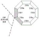
Fig. 2(a) is a schematic range diagram of beam scanning performed by the (1,2) subarray pair formed by the 1 st subarray and the 2 nd subarray in this embodiment; fig. (b) is a schematic view of the range of beam scanning performed by the (2,3) subarray pair formed by the 2 nd and 3 rd sub-wavefront in this embodiment; fig. (c) is a schematic view of the range of beam scanning performed by the pair of (3,4) sub-arrays formed by the 3 rd sub-array and the 4 th sub-array in this embodiment; fig. (d) is a schematic view of the range of beam scanning performed by the (4,5) subarray pair formed by the 4 th subarray and the 5 th subarray in this embodiment; fig. e is a schematic view of the range of beam scanning performed by the (5,6) subarray pair formed by the 5 th and 6 th sub-wavefront in this embodiment; fig. (f) is a schematic view of the range of beam scanning performed by the (6,7) subarray pair formed by the 6 th subarray and the 7 th subarray in this embodiment; fig. g is a schematic view of the range of beam scanning performed by the (7,8) subarray pair formed by the 7 th and 8 th sub-wavefront in this embodiment; fig. h is a schematic view of the range of beam scanning performed by the (8,1) subarray pair formed by the 8 th subarray and the 1 st subarray in this embodiment.
Fig. 3 is a schematic diagram of the internal structure of the low-cost annular phased array radar system of the present embodiment.
Fig. 4 is a schematic diagram of the antennas and the difference pattern of the low cost annular phased array radar system of the present embodiment.
Detailed Description
The technical solutions of the present invention will be described clearly and completely with reference to the accompanying drawings, and it should be understood that the described embodiments are some, but not all embodiments of the present invention. All other embodiments, which can be derived by a person skilled in the art from the embodiments given herein without making any creative effort, shall fall within the protection scope of the present invention.
The invention provides a low-cost annular phased array radar system, which comprises: 2n (n is more than or equal to 4 and is an integer) polygon sub array surfaces which are sequentially arranged and formed, and each sub array surface is provided with 2i×2j(i is not less than 1, j is not less than 1, i and j are integers, 2iDenotes the number of lines, 2jRepresenting the number of columns) antenna elements, i.e. arranged with a total of 2n x 2i×2jOne dayA wire unit; and dividing the 2n sub-array planes into odd sub-array planes (including the 1 st, 3 rd, …, 2n-1 st sub-array planes) and even sub-array planes (including the 2 nd, 4 th, …, 2n sub-array planes); each sub-array is radiated outwards by the antenna element 2i×2jReceives electromagnetic wave signals, and 2i×2jA path echo signal;
the even array surface switch matrix is respectively connected with each even sub-array surface and sequentially gates each even sub-array surface; the odd array surface switch matrix is respectively connected with each odd sub-array surface and sequentially gates each odd sub-array surface;
even array TR elements, set 2i×2jA channel connected with the gated even sub-array plane via the even array plane switch matrix for receiving 2 of the even sub-array planei×2jPerforming phase shift and attenuation operation on the echo signals; odd array face TR component, set 2i×2jA channel connected with one of the gated odd sub-arrays via the odd array switch matrix for receiving 2 of the odd sub-arraysi×2jPerforming phase shift and attenuation operation on the echo signals;
a power dividing and synthesizing network respectively connected with the even array surface TR component and the odd array surface TR component for receiving 2 × 2i×2jPath echo signal, and will be every 2i×2jSynthesizing the echo signals of the/2 paths into 1 path of synthesized signals to be output, and outputting 4 paths of synthesized signals in total;
and the sum and difference network is connected with the power division synthesis network and forms 3 paths of output signals of the sum path, the azimuth path and the pitching path for the received 4 paths of synthesis signals.
Further, the low-cost annular phased array radar system of the present invention further includes: and the matrix switch controller is respectively connected with the even array surface switch matrix and the odd array surface switch matrix, and is used for controlling the even array surface switch matrix to sequentially gate each even sub array surface and controlling the odd array surface switch matrix to sequentially gate each odd sub array surface.
As shown in fig. 2(a) -2 (h), in the low-cost annular phased array radar system according to the present invention, a subarray pair formed by two adjacent subarrays in a polygonal subarray is sequentially selected for operation, and a shadow portion in the figure is the currently selected subarray pair for operation. All combination modes and working sequences of the subarray pairs are as follows: the 1 st sub-wavefront + the 2 nd sub-wavefront, the 2 nd sub-wavefront + the 3 rd sub-wavefront, … …, the 2n-1 st sub-wavefront + the 2n th sub-wavefront, and the 2n th sub-wavefront + the 1 st sub-wavefront. Wherein, each pair of subarrays is formed by combining an even subarray surface and an odd subarray surface.
2 sub array planes in the sub array pair in the current working state simultaneously radiate electromagnetic waves outwards through the antenna unit and receive echo signals; the matrix switch controller controls the even array surface switch matrix to gate the even array surface in the sub array pair in the working state, so that the output echo signal is transmitted to the even array surface TR component. Because the circumferential scanning range of the antenna directional pattern formed by each pair of subarray pairs is 120 degrees, the antenna beam formed by the whole polygonal subarray has 360-degree circumferential scanning capability by sequentially gating each subarray pair.
In addition, due to the adoption of the working mode of sequentially gating each subarray pair, the even array surface TR component and the odd array surface TR component become a switch network of n-to-1, namely n-way input and 1-way output are realized. 2n sub-arrays, 2n x 2, for the entire low cost annular phased array radar systemi×2jAn antenna unit only needing to adopt 2 x 2i×2jAnd a TR component. The traditional method that 1 antenna unit must be connected with 1 TR component is broken through, the number of the TR components is reduced to 1/n, and therefore the cost of the phased array radar system is greatly reduced.
Further, the low-cost annular phased array radar system of the present invention further includes: the wave control machine is respectively connected with the even array surface TR component and the odd array surface TR component, and the wave control machine respectively controls the even array surface TR component and the odd array surface TR component to carry out phase shift and attenuation on the received echo signals, so that the requirement of antenna beam pointing is met.
Further, the antenna units in each sub-array are divided into 2 half arrays with the same number, namely an upper half array and a lower half array, and each half array comprises 2i×2j2 antenna elements, thus receive 2i×2jAnd 2 paths of echo signals. When each pair of subarrays works, the subarrays form 4 half array faces to output 2X 2i×2jAnd (4) a road echo signal. The power division and synthesis network combines 2 in each half array facei×2jThe/2 paths of echo signals are synthesized into 1 path of synthesized signal to be output, and 4 paths of synthesized signals a, b, c and d are synthesized in total and output to a sum-difference network.
Further, the sum and difference network performs the following processing on the 4 paths of synthesized signals a, b, c and d: and (a + b + c + d) is used as a sum path output, and (a + b) - (c + d) are used as azimuth path outputs, and (a + c) - (b + d) are used as elevation path outputs, so that antenna patterns of the sum path, the azimuth path and the elevation path are formed.
In summary, the invention realizes the function of outputting signals of three channels of sum, azimuth and elevation of the annular phased array radar system by pairing the adjacent sub-array surfaces and dividing the upper half array surface and the lower half array surface of each sub-array surface, thereby forming the capabilities of the annular phased array radar system with low cost and differential angle measurement.
Examples
In a preferred embodiment, the low-cost annular phased array radar system of the invention is composed of 8 sub-array planes which are sequentially arranged to form an octagon, 512 antenna units (namely, 64 antenna units are arranged on each sub-array plane), an even array plane switch matrix, an odd array plane switch matrix, 128 TR components (including 64-channel even array plane TR components and 64-channel odd array plane TR components), a power division synthesis network, a sum and difference network, a matrix switch controller and a wave control machine.
Fig. 1 is a schematic diagram of a low-cost annular phased array radar system of this embodiment, and fig. 1 illustrates that, in this embodiment, the low-cost annular phased array radar system of the present invention includes 8 sub-array planes arranged in sequence to form an octagon, and each sub-array plane is provided with 64 (8 rows × 8 columns) antenna units, and there are 512 antenna units in total.
Fig. 2(a) to 2(h) are schematic views of the range of beam scanning by forming the subarray pairs by 8 subarrays according to this embodiment. As shown in fig. 2(a) to 2(h), when the low-cost annular phased array radar system provided in this embodiment operates, a subarray pair formed by two adjacent subarrays in an octagonal subarray surface is sequentially selected, a shadow portion in the figure is a subarray pair currently selected for operation, and all combination modes and an operation sequence of the subarray pair are as follows: (1,2), (2,3), (3,4), (4,5), (5,6), (6,7), (7,8), (8,1), wherein (1,2) represents a subarray pair formed by a 1 st subarray surface and a 2 nd subarray surface, and the like. The 2 sub-arrays in each sub-array pair work simultaneously, radiate electromagnetic waves outwards at the same time, and receive echo signals. Because the scanning angle of the wave beam formed by each subarray pair is 120 degrees, the antenna wave beam has 360-degree circular scanning capability through a mode of sequentially gating the subarrays.
Fig. 3 is a schematic diagram of an internal structure of the low-cost annular phased array radar system according to this embodiment, and as shown in fig. 3, the low-cost annular phased array radar system according to this embodiment of the present invention includes 8 sub-array planes, where each sub-array plane includes 64 antenna units; wherein, even sub-array planes (namely, the 2 nd, 4 th, 6 th and 8 th sub-array planes) are respectively connected with an even array plane switch matrix, odd sub-array planes (namely, the 1 st, 3 rd, 5 th and 7 th sub-array planes) are respectively connected with an odd array plane switch matrix, and the even array plane switch matrix and the odd array plane switch matrix are controlled by a matrix switch controller connected with the even array plane switch matrix and the odd array plane switch matrix; the even array TR component of the 64 channels is connected with the even array switch matrix, the odd array TR component of the 64 channels is connected with the odd array switch matrix, and the even array TR component and the odd array TR component are both controlled by the wave control machine connected with the even array TR component and the odd array TR component; furthermore, the output ends of the even array surface TR component and the odd array surface TR component are both connected with the power division synthesis network, and the output end of the power division synthesis network is connected with the sum-difference network. In this embodiment, the low-cost annular phased array radar system having this configuration can realize a function of sharing 128 TR elements by 512 antenna elements, and can realize cost reduction of the annular phased array radar system.
As shown in fig. 4, which is a schematic diagram of an antenna and a difference pattern of the low-cost annular phased array radar system of the present invention, taking a subarray pair (1,2) as an example, a subarray 1 and every 32 antenna elements in the subarray 2 form 1 half of a wavefront, and each subarray is divided into an upper half of a wavefront and a lower half of a wavefront. The adjacent 2 sub-wavefronts (1,2) work simultaneously, and form 4 half-wavefronts and 128 echo signals. And the echo signals enter the corresponding TR components after passing through the respective array surface switch matrixes. The 128 echo signals enter a power division and synthesis network after being subjected to attenuation and phase shift processing by 128 TR components. The power division synthesis network synthesizes the 32 paths of echo signals of each half of sub-array into 1 path of signal to be output, and synthesizes the 4 paths of synthesized signals a, b, c and d into the sum-difference network after synthesizing 128 paths of echo signals in total. The sum and difference network is in a 4-input, 3-output form. In the sum-difference network, the following processing is carried out on the 4 paths of synthesized signals: and (a + b + c + d) is sum path output, the (a + b) - (c + d) is azimuth path output, and the (a + c) - (b + d) is elevation path output, so that 3 antenna directional patterns of the sum path, the azimuth path and the elevation path are formed. Through the mode of subarray pairing and upper and lower subarray division, the functions of three channel signal output of sum, direction and pitching of the annular phased array radar system can be realized, and the capability of the annular phased array radar system for sum and difference angle measurement is formed.
According to the above-described embodiment, the specific working process is as follows:
step 1, the low-cost annular phased array radar system consists of 8 sub array surfaces, the number of the sub array surfaces is 1-8 according to the clockwise direction, each sub array surface is provided with 64 antenna units, and the total number of the antenna units is 512.
And 2, sequentially selecting 2 adjacent sub-array surfaces to combine into a sub-array pair in working order, wherein the combination order is (1,2), (2,3), (3,4), (4,5), (5,6), (6,7), (7,8), (8, 1). As shown in fig. 2, 2 sub-arrays in the current sub-array pair (1,2) operate simultaneously, and simultaneously radiate 128 electromagnetic wave signals to the outside and receive 128 electromagnetic wave echo signals.
And 3, controlling the even-number array face switch matrix by the matrix switch controller, gating the 2 nd sub-array face to be communicated with the 64-channel even-number array face TR component at the rear end, and receiving 64 paths of echo signals. The matrix switch controller controls the odd-number array face switch matrix to gate the 1 st sub array face to be communicated with the rear end 64-channel odd-number array face TR component and receive 64 paths of echo signals.
And 4, controlling the even-number array surface TR component of the 64 channels and the odd-number array surface TR component of the 64 channels by the wave controller to respectively carry out phase shifting and attenuation on the received echo signals by a phase shifting value and an attenuation value so as to meet the requirement of antenna beam pointing.
And 5, after being attenuated and subjected to phase shift processing by 128 TR components, the total 128 echo signals enter a power division synthesis network. The power division synthesis network synthesizes the total 128 paths of echo signals into 4 paths of synthesized signals and then inputs the signals into the sum-difference network. Specifically, 32 echo signals received by 32 antenna elements included in the upper half wavefront in the 1 st sub-array are power-division-synthesis-network-complexed into a synthesized signal a after passing through the TR element, 32 echo signals received by 32 antenna elements included in the lower half wavefront in the 1 st sub-array are power-division-synthesis-network-complexed into a synthesized signal b after passing through the TR element, 32 echo signals received by 32 antenna elements included in the upper half wavefront in the 2 nd sub-array are power-division-synthesis-network-complexed into a synthesized signal c after passing through the TR element, and 32 echo signals received by 32 antenna elements included in the lower half wavefront in the 2 nd sub-array are power-division-synthesis-network-complexed into a synthesized signal d after passing through the TR element.
And 6, in the sum-difference network, processing the 4 paths of synthesized signals as follows: and (a + b + c + d) is sum path output, the (a + b) - (c + d) is azimuth path output, and the (a + c) - (b + d) is elevation path output, so that 3 antenna directional patterns of the sum path, the azimuth path and the elevation path are formed.
And 7, repeatedly executing the step 2 to the step 6, sequentially selecting the subarray pairs (2,3), (3,4), (4,5), (5,6), (6,7), (7,8) and (8,1) to work, and enabling the antenna beam of the annular phased array radar system to have the 360-degree annular scanning capability. The functions of outputting signals of three channels of sum, direction and pitching of the annular phased array radar system are realized by the sub-array pairing and sub-array division, and the system has the capability of measuring angles with the sum and difference.
In summary, the low-cost annular phased array radar system provided by this embodiment constructs an annular phased array radar system composed of 8 sub-array planes, each sub-array plane has 64 antenna units, and there are 512 antenna units in total. The low-cost annular phased array radar system provided by the invention utilizes the matrix switch controller to control the array surface switch, so that 512 antenna units share 128 TR components, and the mode that 1 antenna unit of the traditional phased array is matched with 1 TR component is broken through. The use amount of the TR component is reduced by three quarters, and the system cost is greatly reduced. On the premise of maintaining the large-range searching and tracking function of the original annular phased array, the use number of TR components is greatly reduced, the system cost is greatly reduced, and the low cost of the array surface is realized. Through field testing in a laboratory and multiple external field actual effect tests, the low-cost annular phased array radar system provided by the invention has engineering realizability and good popularization and application prospects.
While the present invention has been described in detail with reference to the preferred embodiments, it should be understood that the above description should not be taken as limiting the invention. Various modifications and alterations to this invention will become apparent to those skilled in the art upon reading the foregoing description. Accordingly, the scope of the invention should be determined from the following claims.
Claims (9)
1. A low cost annular phased array radar system, comprising:
2n sub-array surfaces which are sequentially arranged to form a polygon, wherein n is more than or equal to 4 and is an integer; each sub array surface is provided with 2i×2jThe antenna units are provided, i is more than or equal to 1, j is more than or equal to 1, and i and j are integers; the 2n sub array surfaces are divided into odd sub array surfaces and even sub array surfaces; each sub-array is radiated outwards by the antenna element 2i×2jReceives electromagnetic wave signals, and 2i×2jA path echo signal;
the even array surface switch matrix is respectively connected with each even sub-array surface and sequentially gates each even sub-array surface; the odd array surface switch matrix is respectively connected with each odd sub-array surface and sequentially gates each odd sub-array surface;
an even array face TR component is providedDevice 2i×2jA channel connected with the gated even sub-array surface through the even array surface switch matrix and receiving 2 of the even sub-array surfacei×2jPerforming phase shift and attenuation operation on the echo signals; odd array face TR component, set 2i×2jA channel connected with the gated odd sub-array surface through the odd array surface switch matrix and receiving 2 of the odd sub-array surfacei×2jPerforming phase shift and attenuation operation on the echo signals;
a power division and synthesis network respectively connected with the even array TR component and the odd array TR component for receiving 2 × 2 signalsi×2j4 paths of synthesized signals are output in total by the path of echo signals;
and the sum and difference network is connected with the power division synthesis network and forms 3 paths of output signals of the sum path, the azimuth path and the pitching path for the received 4 paths of synthesis signals.
2. The low cost annular phased array radar system of claim 1, wherein the radar system has a total of 2n x 2i×2jAn antenna unit provided with 2 × 2i×2jAnd a TR component.
3. The low-cost annular phased array radar system of claim 1, further comprising a matrix switch controller coupled to the even-wavefront switch matrix and the odd-wavefront switch matrix, respectively, the matrix switch controller controlling the even-wavefront switch matrix to sequentially gate each even sub-wavefront and the odd-wavefront switch matrix to sequentially gate each odd sub-wavefront.
4. The low-cost annular phased array radar system of claim 1, further comprising a wave control machine coupled to the even-numbered wavefront TR assembly and the odd-numbered wavefront TR assembly, respectively, the wave control machine controlling phase shift values and attenuation values of the even-numbered wavefront TR assembly and the odd-numbered wavefront TR assembly, respectively, for phase shifting and attenuating the received echo signals.
5. The low cost annular phased array radar system as claimed in claim 1 wherein the antenna elements in each of said sub-wavefronts are divided into 2 equal number of half-wavefronts, and each of said half-wavefronts comprises 2i×2j2 antenna elements, receive 2i×2jAnd 2 paths of echo signals.
6. The low cost annular phased array radar system of claim 5 in which the power splitting combining network combines 2 of each of the half-frontsi×2jThe/2 paths of echo signals are synthesized into 1 path of synthesized signal and output.
7. The low cost annular phased array radar system of claim 1 in which the sum and difference network separately processes the received 4 composite signals a, b, c, d as follows: and (a + b + c + d) is sum path output, the (a + b) - (c + d) is azimuth path output, and the (a + c) - (b + d) is pitch path output, so that three-channel signal output of the sum path, the azimuth path and the pitch path is formed.
8. A method of operating a low cost annular phased array radar system as claimed in any one of claims 1 to 7, the method comprising the steps of:
s1: selecting 2n sub-array planes which are sequentially arranged to form a polygon, wherein n is more than or equal to 4 and is an integer; and dividing the 2n sub-array planes into odd sub-array planes and even sub-array planes; each sub array surface is provided with 2i×2jThe antenna units are provided, i is more than or equal to 1, j is more than or equal to 1, and i and j are integers;
s2: sequentially selecting 2 adjacent sub array surfaces in sequence to form a sub array pair, and simultaneously radiating 2 multiplied by 2 to the outside when the 2 sub array surfaces in the current sub array pair work simultaneouslyi×2jReceiving electromagnetic wave signals simultaneously by 2X 2i×2jAn electromagnetic wave echo signal;
s3: the matrix switch controller controls the even array switch matrix to gate the even sub array in the sub array pair to the back end2i×2jEven array TR elements of a channel are connected to receive 2i×2jA path echo signal; the matrix switch controller controls the odd array switch matrix to gate the odd sub array in the sub array pair to 2 of the back endi×2jOdd array face TR elements of the channel are connected and receive 2i×2jA path echo signal;
s4: wave controller control 2i×2jEven array TR elements and 2 of a channeli×2jThe odd array surface TR components of the channels respectively perform phase shift and attenuation on the received echo signals;
S5:2×2i×2jafter attenuation and phase shift processing, the echo signals enter a power division synthesis network, and the power division synthesis network synthesizes 4 paths of synthesized signals a, b, c and d and outputs the signals to a sum-difference network;
s6: the sum and difference network respectively processes the received 4 paths of composite signals a, b, c and d as follows: (a + b + c + d) is sum path output, (a + b) - (c + d) are azimuth path output, and (a + c) - (b + d) are pitch path output, and form sum path, azimuth path and pitch path three-channel signal output;
s7: and repeatedly executing S2-S6, and sequentially selecting other subarray pairs for work.
9. The method of claim 8 wherein the circumferential scan range of the antenna patterns of the pair of adjacent subarrays formed by two of said subarrays is 120 °, and wherein the 2n antenna beams forming the polygonal shaped sub-array have a 360 ° circumferential scan range.
Priority Applications (1)
| Application Number | Priority Date | Filing Date | Title |
|---|---|---|---|
| CN201910827705.3A CN110376552B (en) | 2019-09-03 | 2019-09-03 | Low-cost annular phased array radar system and working method |
Applications Claiming Priority (1)
| Application Number | Priority Date | Filing Date | Title |
|---|---|---|---|
| CN201910827705.3A CN110376552B (en) | 2019-09-03 | 2019-09-03 | Low-cost annular phased array radar system and working method |
Publications (2)
| Publication Number | Publication Date |
|---|---|
| CN110376552A CN110376552A (en) | 2019-10-25 |
| CN110376552B true CN110376552B (en) | 2021-06-04 |
Family
ID=68261285
Family Applications (1)
| Application Number | Title | Priority Date | Filing Date |
|---|---|---|---|
| CN201910827705.3A Active CN110376552B (en) | 2019-09-03 | 2019-09-03 | Low-cost annular phased array radar system and working method |
Country Status (1)
| Country | Link |
|---|---|
| CN (1) | CN110376552B (en) |
Families Citing this family (5)
| Publication number | Priority date | Publication date | Assignee | Title |
|---|---|---|---|---|
| CN112072309B (en) * | 2020-09-03 | 2023-02-28 | 中国电子科技集团公司第三十八研究所 | A Low-cost Phased Array Antenna Architecture with Step Compensation and Its Design Method |
| CN113541745B (en) * | 2021-07-01 | 2023-03-31 | 军事科学院系统工程研究院网络信息研究所 | Multi-mode dynamic multi-beam antenna system |
| CN115939783B (en) * | 2023-03-09 | 2023-05-16 | 南京誉葆科技股份有限公司 | Conformal radar array antenna system |
| CN116545457B (en) * | 2023-05-09 | 2026-03-31 | 中国电子科技集团公司第三十八研究所 | Multi-channel passive receiver system and signal reception method |
| CN119627436B (en) * | 2024-11-11 | 2025-12-26 | 中国船舶集团有限公司第七二三研究所 | A multioctave phased array design method based on heterogeneous antenna combination |
Citations (3)
| Publication number | Priority date | Publication date | Assignee | Title |
|---|---|---|---|---|
| CN104297747A (en) * | 2014-09-23 | 2015-01-21 | 上海无线电设备研究所 | Phased array beam tracking method |
| CN105259544A (en) * | 2015-10-31 | 2016-01-20 | 零八一电子集团有限公司 | Amplitude and phase test system of active phased-array radar T/R assemblies |
| CN108539418A (en) * | 2018-05-25 | 2018-09-14 | 西安欣创电子技术有限公司 | A kind of Phased Array Radar Antenna control system and method |
Family Cites Families (1)
| Publication number | Priority date | Publication date | Assignee | Title |
|---|---|---|---|---|
| US10847880B2 (en) * | 2016-12-14 | 2020-11-24 | Raytheon Company | Antenna element spacing for a dual frequency electronically scanned array and related techniques |
-
2019
- 2019-09-03 CN CN201910827705.3A patent/CN110376552B/en active Active
Patent Citations (3)
| Publication number | Priority date | Publication date | Assignee | Title |
|---|---|---|---|---|
| CN104297747A (en) * | 2014-09-23 | 2015-01-21 | 上海无线电设备研究所 | Phased array beam tracking method |
| CN105259544A (en) * | 2015-10-31 | 2016-01-20 | 零八一电子集团有限公司 | Amplitude and phase test system of active phased-array radar T/R assemblies |
| CN108539418A (en) * | 2018-05-25 | 2018-09-14 | 西安欣创电子技术有限公司 | A kind of Phased Array Radar Antenna control system and method |
Non-Patent Citations (2)
| Title |
|---|
| "一种基于LXI总线的TR组件S参数自动测试系统的设计";江晓竹 等;《雷达与对抗》;20140630;第34卷(第2期);第62-65页 * |
| "共形相控阵天线的应用与关键技术";张光义;《中国电子科学研究院学报》;20100831;第5卷(第4期);第331-336页 * |
Also Published As
| Publication number | Publication date |
|---|---|
| CN110376552A (en) | 2019-10-25 |
Similar Documents
| Publication | Publication Date | Title |
|---|---|---|
| CN110376552B (en) | Low-cost annular phased array radar system and working method | |
| CN107329134B (en) | A Wave-steered Array Ultra-Wideband Radar Antenna Array Based on Array Element Feeding Waveform Control | |
| CN111859644B (en) | A receiving beam forming and azimuth scanning method for a circular phased array antenna | |
| CN102738583B (en) | Phased-array antenna beam control system based on distribution-centralization type beam control mode | |
| CN108562876A (en) | Broadband low minor lobe simulates multiple-beam array reconnaissance system | |
| CN108037692B (en) | Beam control method of large-scale conformal digital phased array | |
| CN113437529B (en) | A fully polarized active phased array antenna array | |
| CN102955151A (en) | Adaptive cross-polarization active jamming method and device | |
| CN116318278B (en) | Multi-beam forming network and six-beam base station antenna | |
| US10473776B2 (en) | Transmit-array antenna for a monopulse radar system | |
| US20210270883A1 (en) | Method and device for calculating directional pattern of beam pointing adjustable antenna | |
| Schvartzman et al. | Pattern synthesis and digital beamforming capabilities of the fully digital horus radar | |
| US20210242600A1 (en) | Method and device for calculating directional pattern of beam pointing adjustable antenna | |
| Ruiter et al. | Development of a Vivaldi tile for the SKA mid frequency aperture array | |
| Fischman et al. | A digital beamforming processor for the joint DoD/NASA space based radar mission | |
| RU2019006C1 (en) | Ring phased array | |
| CN114563766B (en) | A multi-stage joint array multi-beam reconnaissance false alarm suppression method | |
| CN105024176A (en) | Directional diagram design method of subarray level mixed MIMO-phase array system | |
| RU2383090C1 (en) | Two-dimensional monopulse antenna with electronically controlled beam | |
| Loomis | Digital beamforming-a retrospective | |
| RU2446526C1 (en) | Two-dimensional electronically-controlled beam monopulse phased antenna array | |
| Corey | A survey of Russian low cost phased-array technology | |
| Chen et al. | Wideband irregular subarrayed array design strategy with minimum module quantity | |
| CN115825900B (en) | RF injection simulation method for phased array radar based on equivalent inversion of antenna performance | |
| CN112526510A (en) | Single-channel angle super-resolution method and system based on directional diagram diversity |
Legal Events
| Date | Code | Title | Description |
|---|---|---|---|
| PB01 | Publication | ||
| PB01 | Publication | ||
| SE01 | Entry into force of request for substantive examination | ||
| SE01 | Entry into force of request for substantive examination | ||
| GR01 | Patent grant | ||
| GR01 | Patent grant |