CN110353943B - Exoskeleton robot - Google Patents
Exoskeleton robot Download PDFInfo
- Publication number
- CN110353943B CN110353943B CN201910695988.0A CN201910695988A CN110353943B CN 110353943 B CN110353943 B CN 110353943B CN 201910695988 A CN201910695988 A CN 201910695988A CN 110353943 B CN110353943 B CN 110353943B
- Authority
- CN
- China
- Prior art keywords
- fixedly connected
- rods
- mechanisms
- positioning
- rod
- Prior art date
- Legal status (The legal status is an assumption and is not a legal conclusion. Google has not performed a legal analysis and makes no representation as to the accuracy of the status listed.)
- Active
Links
Images


Classifications
-
- A—HUMAN NECESSITIES
- A61—MEDICAL OR VETERINARY SCIENCE; HYGIENE
- A61H—PHYSICAL THERAPY APPARATUS, e.g. DEVICES FOR LOCATING OR STIMULATING REFLEX POINTS IN THE BODY; ARTIFICIAL RESPIRATION; MASSAGE; BATHING DEVICES FOR SPECIAL THERAPEUTIC OR HYGIENIC PURPOSES OR SPECIFIC PARTS OF THE BODY
- A61H1/00—Apparatus for passive exercising; Vibrating apparatus ; Chiropractic devices, e.g. body impacting devices, external devices for briefly extending or aligning unbroken bones
- A61H1/02—Stretching or bending or torsioning apparatus for exercising
- A61H1/0237—Stretching or bending or torsioning apparatus for exercising for the lower limbs
- A61H1/0255—Both knee and hip of a patient, e.g. in supine or sitting position, the feet being moved in a plane substantially parallel to the body-symmetrical-plane
- A61H1/0262—Walking movement; Appliances for aiding disabled persons to walk
-
- A—HUMAN NECESSITIES
- A61—MEDICAL OR VETERINARY SCIENCE; HYGIENE
- A61H—PHYSICAL THERAPY APPARATUS, e.g. DEVICES FOR LOCATING OR STIMULATING REFLEX POINTS IN THE BODY; ARTIFICIAL RESPIRATION; MASSAGE; BATHING DEVICES FOR SPECIAL THERAPEUTIC OR HYGIENIC PURPOSES OR SPECIFIC PARTS OF THE BODY
- A61H3/00—Appliances for aiding patients or disabled persons to walk about
-
- B—PERFORMING OPERATIONS; TRANSPORTING
- B25—HAND TOOLS; PORTABLE POWER-DRIVEN TOOLS; MANIPULATORS
- B25J—MANIPULATORS; CHAMBERS PROVIDED WITH MANIPULATION DEVICES
- B25J9/00—Programme-controlled manipulators
- B25J9/0006—Exoskeletons, i.e. resembling a human figure
-
- A—HUMAN NECESSITIES
- A61—MEDICAL OR VETERINARY SCIENCE; HYGIENE
- A61H—PHYSICAL THERAPY APPARATUS, e.g. DEVICES FOR LOCATING OR STIMULATING REFLEX POINTS IN THE BODY; ARTIFICIAL RESPIRATION; MASSAGE; BATHING DEVICES FOR SPECIAL THERAPEUTIC OR HYGIENIC PURPOSES OR SPECIFIC PARTS OF THE BODY
- A61H3/00—Appliances for aiding patients or disabled persons to walk about
- A61H2003/005—Appliances for aiding patients or disabled persons to walk about with knee, leg or stump rests
-
- A—HUMAN NECESSITIES
- A61—MEDICAL OR VETERINARY SCIENCE; HYGIENE
- A61H—PHYSICAL THERAPY APPARATUS, e.g. DEVICES FOR LOCATING OR STIMULATING REFLEX POINTS IN THE BODY; ARTIFICIAL RESPIRATION; MASSAGE; BATHING DEVICES FOR SPECIAL THERAPEUTIC OR HYGIENIC PURPOSES OR SPECIFIC PARTS OF THE BODY
- A61H3/00—Appliances for aiding patients or disabled persons to walk about
- A61H2003/007—Appliances for aiding patients or disabled persons to walk about secured to the patient, e.g. with belts
-
- A—HUMAN NECESSITIES
- A61—MEDICAL OR VETERINARY SCIENCE; HYGIENE
- A61H—PHYSICAL THERAPY APPARATUS, e.g. DEVICES FOR LOCATING OR STIMULATING REFLEX POINTS IN THE BODY; ARTIFICIAL RESPIRATION; MASSAGE; BATHING DEVICES FOR SPECIAL THERAPEUTIC OR HYGIENIC PURPOSES OR SPECIFIC PARTS OF THE BODY
- A61H2201/00—Characteristics of apparatus not provided for in the preceding codes
- A61H2201/14—Special force transmission means, i.e. between the driving means and the interface with the user
-
- A—HUMAN NECESSITIES
- A61—MEDICAL OR VETERINARY SCIENCE; HYGIENE
- A61H—PHYSICAL THERAPY APPARATUS, e.g. DEVICES FOR LOCATING OR STIMULATING REFLEX POINTS IN THE BODY; ARTIFICIAL RESPIRATION; MASSAGE; BATHING DEVICES FOR SPECIAL THERAPEUTIC OR HYGIENIC PURPOSES OR SPECIFIC PARTS OF THE BODY
- A61H2201/00—Characteristics of apparatus not provided for in the preceding codes
- A61H2201/16—Physical interface with patient
- A61H2201/1602—Physical interface with patient kind of interface, e.g. head rest, knee support or lumbar support
- A61H2201/164—Feet or leg, e.g. pedal
- A61H2201/1642—Holding means therefor
-
- A—HUMAN NECESSITIES
- A61—MEDICAL OR VETERINARY SCIENCE; HYGIENE
- A61H—PHYSICAL THERAPY APPARATUS, e.g. DEVICES FOR LOCATING OR STIMULATING REFLEX POINTS IN THE BODY; ARTIFICIAL RESPIRATION; MASSAGE; BATHING DEVICES FOR SPECIAL THERAPEUTIC OR HYGIENIC PURPOSES OR SPECIFIC PARTS OF THE BODY
- A61H2201/00—Characteristics of apparatus not provided for in the preceding codes
- A61H2201/16—Physical interface with patient
- A61H2201/1657—Movement of interface, i.e. force application means
- A61H2201/1659—Free spatial automatic movement of interface within a working area, e.g. Robot
-
- A—HUMAN NECESSITIES
- A61—MEDICAL OR VETERINARY SCIENCE; HYGIENE
- A61H—PHYSICAL THERAPY APPARATUS, e.g. DEVICES FOR LOCATING OR STIMULATING REFLEX POINTS IN THE BODY; ARTIFICIAL RESPIRATION; MASSAGE; BATHING DEVICES FOR SPECIAL THERAPEUTIC OR HYGIENIC PURPOSES OR SPECIFIC PARTS OF THE BODY
- A61H2201/00—Characteristics of apparatus not provided for in the preceding codes
- A61H2201/50—Control means thereof
-
- A—HUMAN NECESSITIES
- A61—MEDICAL OR VETERINARY SCIENCE; HYGIENE
- A61H—PHYSICAL THERAPY APPARATUS, e.g. DEVICES FOR LOCATING OR STIMULATING REFLEX POINTS IN THE BODY; ARTIFICIAL RESPIRATION; MASSAGE; BATHING DEVICES FOR SPECIAL THERAPEUTIC OR HYGIENIC PURPOSES OR SPECIFIC PARTS OF THE BODY
- A61H2205/00—Devices for specific parts of the body
- A61H2205/10—Leg
-
- A—HUMAN NECESSITIES
- A61—MEDICAL OR VETERINARY SCIENCE; HYGIENE
- A61H—PHYSICAL THERAPY APPARATUS, e.g. DEVICES FOR LOCATING OR STIMULATING REFLEX POINTS IN THE BODY; ARTIFICIAL RESPIRATION; MASSAGE; BATHING DEVICES FOR SPECIAL THERAPEUTIC OR HYGIENIC PURPOSES OR SPECIFIC PARTS OF THE BODY
- A61H2205/00—Devices for specific parts of the body
- A61H2205/12—Feet
Abstract
The invention discloses an exoskeleton robot, which comprises two support rods arranged in parallel, wherein the lower surfaces of the two support rods are respectively and rotatably connected with a movable joint mechanism, the side walls of the opposite sides of the two movable joint mechanisms are respectively and fixedly connected with two fixing mechanisms in a symmetrical shape, the lower ends of the two movable joint mechanisms are respectively and rotatably connected with a foot placing mechanism, the invention relates to an exoskeleton robot, in specific use, the feet of a user are placed in the foot placing mechanisms, the thighs and the calves of the user are respectively fixed through the four fixing mechanisms, then the waist of the user is fixed through the waist supporting mechanism, when carrying out the rehabilitation training when using, positioning mechanism prescribes a limit to user's step activity angle, thereby avoided some patient that the low limbs are weak or the obstacle to tumble because of unable control when carrying out the rehabilitation.
Description
Technical Field
The invention belongs to the technical field of exoskeleton, and particularly relates to an exoskeleton robot.
Background
With the advancement of medical technology, more and more treatment means can help patients with weakness or disorder of lower limbs to perform rehabilitation, such as exoskeleton robots.
When the existing exoskeleton robot is used, most of the existing exoskeleton robots are supported by users themselves and are not provided with a good limiting device, so that patients with weak or obstacle lower limbs can recover and cannot be controlled to fall down easily.
Disclosure of Invention
The invention aims to solve the problems, and provides an exoskeleton robot which solves the problem that most of the existing exoskeleton robots are supported by users themselves when in use, and a good limiting device is not provided, so that patients with limb weakness or obstacle can not be controlled to recover and fall easily.
In order to solve the above problems, the present invention provides a technical solution:
the utility model provides an ectoskeleton robot, includes two bracing pieces that are the form setting of running parallel, two the lower surface of bracing piece all rotates and is connected with a freely movable joint mechanism, two be two fixed establishment of the equal fixedly connected with of symmetry form on the lateral wall of freely movable joint mechanism one side in opposite directions, two freely movable joint mechanism's lower extreme all rotates and is connected with a foot placement machine and constructs, two waist supporting mechanism of the common fixedly connected with of one of them one end of bracing piece is located two positioning mechanism of the equal fixedly connected with of two bracing piece lower surface of freely movable joint mechanism one side.
Preferably, the two movable joint mechanisms comprise first telescopic rods, the upper ends of the first telescopic rods are respectively connected to the lower surfaces of the two support rods in a rotating mode through first rotating shafts, the lower ends of the first telescopic rods are respectively connected with second telescopic rods in a rotating mode through second rotating shafts, and the first telescopic rods and the two second telescopic rods are symmetrically arranged about the second rotating shafts.
Preferably, the four fixing mechanisms comprise an arc-shaped block, the four arc-shaped blocks are respectively and fixedly connected to opposite side walls of the two first telescopic rods and the two second telescopic rods, a first cushion pad is fixedly connected to the inner side walls of the four arc-shaped blocks, the four first cushion pads are made of sponge materials, and a first buckling belt is fixedly connected to the four arc-shaped blocks.
Preferably, the foot placing mechanisms comprise connecting blocks, the connecting blocks are respectively connected to the lower ends of the two second telescopic rods through third rotating shafts in a rotating mode, the lower ends of the connecting blocks are fixedly connected with a placing plate, and the upper surface of the placing plate corresponds to one upper of the shoe in one side edge of the connecting block.
Preferably, the lumbar support mechanism comprises a connecting rod, the connecting rod is fixedly connected to one end of each of the two support rods, a support plate is fixedly connected to the upper surface of the connecting rod, a second cushion pad is fixedly connected to the side wall of one side of the support plate, the second cushion pad is made of sponge materials, and a second buckling belt is fixedly connected to the support plate.
Preferably, the two positioning mechanisms respectively comprise a fixing rod, the upper ends of the fixing rods are respectively fixedly connected to one side edge of the lower surfaces of the two supporting rods, the two fixing rods are respectively provided with a positioning hole in a penetrating manner at positions corresponding to the two second telescopic rods, a positioning rod is slidably connected into the positioning holes, the two positioning rods are respectively arranged in the two positioning holes in a penetrating manner, one end of each positioning rod, which is positioned outside the corresponding fixing rod, is respectively rotatably connected to the two second telescopic rods through a fourth rotating shaft, and a limiting rod is fixedly connected to the other end of each positioning rod, which is positioned outside the corresponding fixing rod.
Preferably, the two movable joint mechanisms, the four fixing mechanisms, the two foot placing mechanisms and the two positioning mechanisms are symmetrically arranged around the center of the connecting rod.
The invention has the beneficial effects that: the invention relates to an exoskeleton robot, which is characterized in that when in specific use, feet of a user are placed in a foot placing mechanism, thighs and shanks of the user are respectively fixed through four fixing mechanisms, and then the waist of the user is fixed through a waist supporting mechanism.
Description of the drawings:
for ease of illustration, the invention is described in detail by the following detailed description and the accompanying drawings.
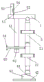
FIG. 1 is a schematic view of the overall structure of the present invention;
FIG. 2 is a schematic view of the left side of the present invention;
FIG. 3 is a right side sectional view of the present invention;
FIG. 4 is a schematic top view of the present invention;
fig. 5 is a schematic top view of the fixing mechanism of the present invention.
In the figure: 1. a support bar; 2. a movable joint mechanism; 21. a first telescopic rod; 22. a second telescopic rod; 3. a fixing mechanism; 31. an arc-shaped block; 32. a first cushion pad; 33. a first fastener tape; 4. a foot placement mechanism; 41. connecting blocks; 42. placing the plate; 43. an upper; 5. a lumbar support mechanism; 51. a connecting rod; 52. a support plate; 53. a second cushion pad; 54. a second fastener tape; 6. a positioning mechanism; 61. fixing the rod; 62. positioning holes; 63. positioning a rod; 64. a limiting rod.
The specific implementation mode is as follows:
as shown in fig. 1 to 5, the following technical solutions are adopted in the present embodiment:
example (b):
the utility model provides an ectoskeleton robot, includes two bracing pieces 1 that are the form setting of running parallel, two the lower surface of bracing piece 1 all rotates and is connected with a swing joint mechanism 2, two be two the equal fixedly connected with two fixed establishment 3 of symmetry form, two on the lateral wall of one side in opposite directions of swing joint mechanism 2 the lower extreme of swing joint mechanism 2 all rotates and is connected with a foot and places the mechanism 4, two the common fixedly connected with waist supporting mechanism 5 of one of them one end of bracing piece 1 is located two the equal fixedly connected with positioning mechanism 6 of two bracing pieces 1 lower surface of 2 one sides of swing joint mechanism.
Wherein, two the swing joint mechanism 2 all includes a first telescopic link 21, two the upper end of first telescopic link 21 all rotates respectively through first pivot and connects at the lower surface of two spinal branch vaulting poles 1, two the lower extreme of first telescopic link 21 all rotates through the second pivot and is connected with a second telescopic link 22, two first telescopic link 21 and two second telescopic links 22 are the symmetry about the second pivot and describe the setting.
Four fixing mechanism 3 all includes an arc piece 31, four arc piece 31 fixed connection respectively is on two first telescopic link 21 and two second telescopic link 22 lateral walls in opposite directions four equal first blotter 32 of fixedly connected with one deck on the inside wall of arc piece 31, four the first blotter 32 all adopts sponge material to make, four equal first hasp area 33 of fixedly connected with on the arc piece 31 offsets user's both legs lateral wall and the first blotter 32 on the four arc piece 31 inside walls, then fixes user's thigh and shank portion respectively through four first hasp areas 33 for can drive freely movable joint mechanism 2 when user's shank activity moves about.
Wherein, two the foot placement mechanism 4 all includes a connecting block 41, two connecting block 41 all rotates respectively through the third pivot and connects the lower extreme at two second telescopic links 22, two board 42 is placed to the equal fixedly connected with of lower extreme of connecting block 41, two place board 42's the equal fixedly connected with upper of a shoe 43 of one side edge that the upper surface corresponds connecting block 41, place on board 42 through placing user's foot to in stretching into upper of a shoe 43 with the tiptoe part, fix user's foot.
The lumbar support mechanism 5 comprises a connecting rod 51, the connecting rod 51 is fixedly connected to one end of the two support rods 1, a support plate 52 is fixedly connected to the upper surface of the connecting rod 51, a second cushion pad 53 is fixedly connected to the side wall of one side of the support plate 52, the second cushion pad 53 is made of sponge materials, a second buckling belt 54 is fixedly connected to the support plate 52, the waist is abutted to the second cushion pad 53 on the support plate 52, and then the waist of a user is fixed through the second buckling belt 54, so that the user can be prevented from falling down when the lumbar support mechanism is used.
Wherein, the two positioning mechanisms 6 each comprise a fixing rod 61, the upper ends of the two fixing rods 61 are respectively fixedly connected to one side edge of the lower surface of the two support rods 1, the two fixing rods 61 are respectively provided with a positioning hole 62 corresponding to the positions of the two second telescopic rods 22, a positioning rod 63 is respectively connected in the two positioning holes 62 in a sliding manner, the two positioning rods 63 are respectively arranged in the two positioning holes 62 in a penetrating manner, one end of each positioning rod 63 located outside the fixing rod 61 is respectively connected to the two second telescopic rods 22 in a rotating manner through a fourth rotating shaft, the other end of each positioning rod 63 located outside the fixing rod 61 is respectively fixedly connected with a limiting rod 64, when the device is moved, the positioning rod 63 is driven to slide in the positioning hole 62, when the second telescopic rod 22 and the first telescopic rod 21 move to a certain angle, the limiting rod 64 can be abutted against the fixing rod 61, so that the angle between the second telescopic rod 22 and the first telescopic rod 21 cannot be changed, the movable angle of the knee joint of a user is limited, and the situation that some patients with weak lower limbs or obstacles fall down due to incapability of controlling when rehabilitation is carried out is avoided.
The two movable joint mechanisms 2, the four fixing mechanisms 3, the two foot placing mechanisms 4 and the two positioning mechanisms 6 are symmetrically arranged around the center of the connecting rod 51.
The using state of the invention is as follows: the invention relates to an exoskeleton robot, in specific use, firstly, feet of a user are placed on a placing plate 42, toe parts of the feet of the user extend into an upper 43 to fix the feet of the user, then the outer side walls of the two legs of the user are abutted against first buffer pads 32 on the inner side walls of four arc-shaped blocks 31, then the thighs and the calf parts of the user are respectively fixed through four first buckling belts 33, so that the legs of the user can drive a movable joint mechanism 2 to move when moving, the waist is abutted against second buffer pads 53 on a supporting plate 52 after the fixing is finished, then the waist of the user is fixed through second buckling belts 54, the phenomenon that the user topples over when using the exoskeleton robot can be avoided, the user can drive a device body to move when performing rehabilitation training, and meanwhile, a positioning rod 63 is driven to slide in a positioning hole 62 when the device moves, when the second telescopic link 22 and the first telescopic link 21 move to a certain angle, the limiting rod 64 can be abutted against the fixing rod 61, so that the angle of the second telescopic link 22 and the angle of the first telescopic link 21 cannot be changed, the movable angle of the knee joint of a user is limited, and the situation that some patients with weak lower limbs or obstacles fall down due to incapability of controlling when rehabilitation is carried out is avoided.
While there have been shown and described what are at present considered to be the fundamental principles of the invention and its essential features and advantages, it will be understood by those skilled in the art that the invention is not limited by the embodiments described above, which are merely illustrative of the principles of the invention, but that various changes and modifications may be made therein without departing from the spirit and scope of the invention as defined by the appended claims and their equivalents.
Claims (1)
1. An exoskeleton robot is characterized by comprising two support rods (1) which are arranged in parallel, wherein the lower surfaces of the two support rods (1) are rotatably connected with a movable joint mechanism (2), the side walls of the opposite sides of the two movable joint mechanisms (2) are symmetrically and fixedly connected with two fixing mechanisms (3), the lower ends of the two movable joint mechanisms (2) are rotatably connected with a foot placing mechanism (4), one end of each support rod (1) is fixedly connected with a waist supporting mechanism (5), and the lower surfaces of the two support rods (1) positioned on one side of the two movable joint mechanisms (2) are fixedly connected with a positioning mechanism (6);
the two movable joint mechanisms (2) respectively comprise a first telescopic rod (21), the upper ends of the two first telescopic rods (21) are respectively and rotatably connected to the lower surfaces of the two support rods (1) through first rotating shafts, the lower ends of the two first telescopic rods (21) are respectively and rotatably connected with a second telescopic rod (22) through second rotating shafts, and the two first telescopic rods (21) and the two second telescopic rods (22) are symmetrically arranged around the second rotating shafts;
the four fixing mechanisms (3) respectively comprise an arc-shaped block (31), the four arc-shaped blocks (31) are respectively and fixedly connected to the opposite side walls of the two first telescopic rods (21) and the two second telescopic rods (22), a layer of first buffer cushion (32) is respectively and fixedly connected to the inner side walls of the four arc-shaped blocks (31), the four layers of first buffer cushions (32) are made of sponge materials, and the four arc-shaped blocks (31) are respectively and fixedly connected with a first buckling belt (33);
the two foot placing mechanisms (4) respectively comprise a connecting block (41), the two connecting blocks (41) are respectively and rotatably connected to the lower ends of the two second telescopic rods (22) through third rotating shafts, the lower ends of the two connecting blocks (41) are respectively and fixedly connected with a placing plate (42), and one upper (43) is fixedly connected to one side edge of the upper surface of each placing plate (42) corresponding to the connecting block (41);
the lumbar support mechanism (5) comprises a connecting rod (51), the connecting rod (51) is fixedly connected to one end of the two support rods (1), the upper surface of the connecting rod (51) is fixedly connected with a support plate (52), a layer of second cushion pad (53) is fixedly connected to the side wall of one side of the support plate (52), the second cushion pad (53) is made of sponge materials, and a second buckling belt (54) is fixedly connected to the support plate (52);
the two positioning mechanisms (6) respectively comprise a fixing rod (61), the upper ends of the two fixing rods (61) are respectively and fixedly connected to one side edge of the lower surfaces of the two support rods (1), the positions, corresponding to the two second telescopic rods (22), of the two fixing rods (61) are respectively provided with a positioning hole (62) in a penetrating manner, a positioning rod (63) is respectively and slidably connected into the two positioning holes (62), the two positioning rods (63) are respectively arranged in a penetrating manner through the two positioning holes (62), one ends, located outside the fixing rods (61), of the two positioning rods (63) are respectively and rotatably connected to the two second telescopic rods (22) through a fourth rotating shaft, and the other ends, located outside the fixing rods (61), of the two positioning rods (63) are respectively and fixedly connected with a limiting rod (64);
the two movable joint mechanisms (2), the four fixing mechanisms (3), the two foot placing mechanisms (4) and the two positioning mechanisms (6) are symmetrically arranged around the center of the connecting rod (51).
Priority Applications (1)
| Application Number | Priority Date | Filing Date | Title |
|---|---|---|---|
| CN201910695988.0A CN110353943B (en) | 2019-07-30 | 2019-07-30 | Exoskeleton robot |
Applications Claiming Priority (1)
| Application Number | Priority Date | Filing Date | Title |
|---|---|---|---|
| CN201910695988.0A CN110353943B (en) | 2019-07-30 | 2019-07-30 | Exoskeleton robot |
Publications (2)
| Publication Number | Publication Date |
|---|---|
| CN110353943A CN110353943A (en) | 2019-10-22 |
| CN110353943B true CN110353943B (en) | 2021-11-09 |
Family
ID=68222258
Family Applications (1)
| Application Number | Title | Priority Date | Filing Date |
|---|---|---|---|
| CN201910695988.0A Active CN110353943B (en) | 2019-07-30 | 2019-07-30 | Exoskeleton robot |
Country Status (1)
| Country | Link |
|---|---|
| CN (1) | CN110353943B (en) |
Families Citing this family (1)
| Publication number | Priority date | Publication date | Assignee | Title |
|---|---|---|---|---|
| CN110974243B (en) * | 2020-01-03 | 2022-03-15 | 安徽理工大学 | Wearable falling prevention device |
Citations (6)
| Publication number | Priority date | Publication date | Assignee | Title |
|---|---|---|---|---|
| CN103610568A (en) * | 2013-12-16 | 2014-03-05 | 哈尔滨工业大学 | Human-simulated external skeleton robot assisting lower limbs |
| CN204951522U (en) * | 2015-09-11 | 2016-01-13 | 绍兴文理学院 | Recovered auxiliary device of be injured patient |
| CN107320292A (en) * | 2017-08-07 | 2017-11-07 | 南京理工大学 | A kind of wearable ectoskeleton power assisting device of tubular modulesization and its control method |
| CN107411939A (en) * | 2017-07-24 | 2017-12-01 | 燕山大学 | A kind of special power-assisted healing robot of single lower limb individuals with disabilities |
| CN207341899U (en) * | 2017-03-17 | 2018-05-11 | 河南科技大学 | A kind of Multifunctional rehabilitation exercise equipment |
| CN109702715A (en) * | 2018-12-06 | 2019-05-03 | 西安交通大学 | A kind of mechanical ectoskeleton seat |
Family Cites Families (4)
| Publication number | Priority date | Publication date | Assignee | Title |
|---|---|---|---|---|
| CN204468352U (en) * | 2015-02-24 | 2015-07-15 | 吴娟 | Human body lower limbs ESD |
| CN209122688U (en) * | 2018-04-14 | 2019-07-19 | 陈治清 | A kind of adjustable bed head bracket of hospital |
| CN108478992A (en) * | 2018-05-31 | 2018-09-04 | 成都言行果科技有限公司 | A kind of sports equipment |
| CN108969296A (en) * | 2018-06-13 | 2018-12-11 | 哈尔滨工业大学(威海) | A kind of lower limb rehabilitation robot |
-
2019
- 2019-07-30 CN CN201910695988.0A patent/CN110353943B/en active Active
Patent Citations (6)
| Publication number | Priority date | Publication date | Assignee | Title |
|---|---|---|---|---|
| CN103610568A (en) * | 2013-12-16 | 2014-03-05 | 哈尔滨工业大学 | Human-simulated external skeleton robot assisting lower limbs |
| CN204951522U (en) * | 2015-09-11 | 2016-01-13 | 绍兴文理学院 | Recovered auxiliary device of be injured patient |
| CN207341899U (en) * | 2017-03-17 | 2018-05-11 | 河南科技大学 | A kind of Multifunctional rehabilitation exercise equipment |
| CN107411939A (en) * | 2017-07-24 | 2017-12-01 | 燕山大学 | A kind of special power-assisted healing robot of single lower limb individuals with disabilities |
| CN107320292A (en) * | 2017-08-07 | 2017-11-07 | 南京理工大学 | A kind of wearable ectoskeleton power assisting device of tubular modulesization and its control method |
| CN109702715A (en) * | 2018-12-06 | 2019-05-03 | 西安交通大学 | A kind of mechanical ectoskeleton seat |
Also Published As
| Publication number | Publication date |
|---|---|
| CN110353943A (en) | 2019-10-22 |
Similar Documents
| Publication | Publication Date | Title |
|---|---|---|
| CN206809645U (en) | A kind of healing hemiplegic lower limb instrument for training based on the linkage of strong side | |
| CN102499854B (en) | Parallel structure type ankle joint rehabilitation training device | |
| CN115487042A (en) | Cardiovascular heart rehabilitation training device | |
| CN212548128U (en) | Ankle pump athletic training equipment | |
| CN101999970A (en) | Parallel multi-degree-of-freedom ankle joint rehabilitation trainer | |
| CN109700637A (en) | A kind of robot for rehabilitation of anklebone | |
| CN209036530U (en) | A kind of adaptive knee-joint rehabilitation training ectoskeleton of multiple degrees of freedom | |
| CN209695749U (en) | A kind of robot for rehabilitation of anklebone | |
| CN107296717B (en) | Orthopedic limb simulation exercise rehabilitation machine | |
| CN109318208A (en) | A kind of adaptive knee-joint rehabilitation training ectoskeleton of multiple degrees of freedom | |
| CN108743224A (en) | Leg rehabilitation training and body-building exoskeleton robot | |
| KR101230458B1 (en) | Rehabilitation machine device for knee joint | |
| CN110353943B (en) | Exoskeleton robot | |
| JP2004089616A (en) | Joint drive assembly | |
| CN206508469U (en) | A kind of device for rehabilitation | |
| CN108938325A (en) | Lower limb body recovery exercising robot | |
| CN207590930U (en) | A kind of rehabilitation treatment bed for being suitable for the elderly | |
| CN108567546A (en) | A kind of wearable ankle rehabilitation parallel robot and its application method of four-degree-of-freedom | |
| CN109106531B (en) | Multi-joint auxiliary exercise bed | |
| CN209048595U (en) | A kind of hip bending knee device for healing and training in the wrong | |
| CN114733145B (en) | Intelligent multifunctional lower limb rehabilitation training integrated machine | |
| CN212880797U (en) | Recovered shank exercise device of using | |
| CN209827463U (en) | Sports medicine joint postoperative rehabilitation trainer | |
| JP6089253B2 (en) | Tilt table for crus movement support | |
| CN112603765A (en) | Leg exercise auxiliary instrument based on biomechanics |
Legal Events
| Date | Code | Title | Description |
|---|---|---|---|
| PB01 | Publication | ||
| PB01 | Publication | ||
| SE01 | Entry into force of request for substantive examination | ||
| SE01 | Entry into force of request for substantive examination | ||
| GR01 | Patent grant | ||
| GR01 | Patent grant |