CN110293760B - Liquid ejecting apparatus - Google Patents
Liquid ejecting apparatus Download PDFInfo
- Publication number
- CN110293760B CN110293760B CN201910212633.1A CN201910212633A CN110293760B CN 110293760 B CN110293760 B CN 110293760B CN 201910212633 A CN201910212633 A CN 201910212633A CN 110293760 B CN110293760 B CN 110293760B
- Authority
- CN
- China
- Prior art keywords
- ejection
- liquid
- pressure chamber
- failure
- nozzle
- Prior art date
- Legal status (The legal status is an assumption and is not a legal conclusion. Google has not performed a legal analysis and makes no representation as to the accuracy of the status listed.)
- Active
Links
Images


Classifications
-
- B—PERFORMING OPERATIONS; TRANSPORTING
- B41—PRINTING; LINING MACHINES; TYPEWRITERS; STAMPS
- B41J—TYPEWRITERS; SELECTIVE PRINTING MECHANISMS, i.e. MECHANISMS PRINTING OTHERWISE THAN FROM A FORME; CORRECTION OF TYPOGRAPHICAL ERRORS
- B41J2/00—Typewriters or selective printing mechanisms characterised by the printing or marking process for which they are designed
- B41J2/005—Typewriters or selective printing mechanisms characterised by the printing or marking process for which they are designed characterised by bringing liquid or particles selectively into contact with a printing material
- B41J2/01—Ink jet
- B41J2/015—Ink jet characterised by the jet generation process
- B41J2/04—Ink jet characterised by the jet generation process generating single droplets or particles on demand
- B41J2/045—Ink jet characterised by the jet generation process generating single droplets or particles on demand by pressure, e.g. electromechanical transducers
- B41J2/04501—Control methods or devices therefor, e.g. driver circuits, control circuits
- B41J2/0451—Control methods or devices therefor, e.g. driver circuits, control circuits for detecting failure, e.g. clogging, malfunctioning actuator
-
- B—PERFORMING OPERATIONS; TRANSPORTING
- B41—PRINTING; LINING MACHINES; TYPEWRITERS; STAMPS
- B41J—TYPEWRITERS; SELECTIVE PRINTING MECHANISMS, i.e. MECHANISMS PRINTING OTHERWISE THAN FROM A FORME; CORRECTION OF TYPOGRAPHICAL ERRORS
- B41J2/00—Typewriters or selective printing mechanisms characterised by the printing or marking process for which they are designed
- B41J2/005—Typewriters or selective printing mechanisms characterised by the printing or marking process for which they are designed characterised by bringing liquid or particles selectively into contact with a printing material
- B41J2/01—Ink jet
- B41J2/015—Ink jet characterised by the jet generation process
- B41J2/04—Ink jet characterised by the jet generation process generating single droplets or particles on demand
- B41J2/045—Ink jet characterised by the jet generation process generating single droplets or particles on demand by pressure, e.g. electromechanical transducers
- B41J2/04501—Control methods or devices therefor, e.g. driver circuits, control circuits
- B41J2/04553—Control methods or devices therefor, e.g. driver circuits, control circuits detecting ambient temperature
-
- B—PERFORMING OPERATIONS; TRANSPORTING
- B41—PRINTING; LINING MACHINES; TYPEWRITERS; STAMPS
- B41J—TYPEWRITERS; SELECTIVE PRINTING MECHANISMS, i.e. MECHANISMS PRINTING OTHERWISE THAN FROM A FORME; CORRECTION OF TYPOGRAPHICAL ERRORS
- B41J2/00—Typewriters or selective printing mechanisms characterised by the printing or marking process for which they are designed
- B41J2/005—Typewriters or selective printing mechanisms characterised by the printing or marking process for which they are designed characterised by bringing liquid or particles selectively into contact with a printing material
- B41J2/01—Ink jet
- B41J2/015—Ink jet characterised by the jet generation process
- B41J2/04—Ink jet characterised by the jet generation process generating single droplets or particles on demand
- B41J2/045—Ink jet characterised by the jet generation process generating single droplets or particles on demand by pressure, e.g. electromechanical transducers
- B41J2/04501—Control methods or devices therefor, e.g. driver circuits, control circuits
- B41J2/04563—Control methods or devices therefor, e.g. driver circuits, control circuits detecting head temperature; Ink temperature
-
- B—PERFORMING OPERATIONS; TRANSPORTING
- B41—PRINTING; LINING MACHINES; TYPEWRITERS; STAMPS
- B41J—TYPEWRITERS; SELECTIVE PRINTING MECHANISMS, i.e. MECHANISMS PRINTING OTHERWISE THAN FROM A FORME; CORRECTION OF TYPOGRAPHICAL ERRORS
- B41J2/00—Typewriters or selective printing mechanisms characterised by the printing or marking process for which they are designed
- B41J2/005—Typewriters or selective printing mechanisms characterised by the printing or marking process for which they are designed characterised by bringing liquid or particles selectively into contact with a printing material
- B41J2/01—Ink jet
- B41J2/015—Ink jet characterised by the jet generation process
- B41J2/04—Ink jet characterised by the jet generation process generating single droplets or particles on demand
- B41J2/045—Ink jet characterised by the jet generation process generating single droplets or particles on demand by pressure, e.g. electromechanical transducers
- B41J2/04501—Control methods or devices therefor, e.g. driver circuits, control circuits
- B41J2/04571—Control methods or devices therefor, e.g. driver circuits, control circuits detecting viscosity
-
- B—PERFORMING OPERATIONS; TRANSPORTING
- B41—PRINTING; LINING MACHINES; TYPEWRITERS; STAMPS
- B41J—TYPEWRITERS; SELECTIVE PRINTING MECHANISMS, i.e. MECHANISMS PRINTING OTHERWISE THAN FROM A FORME; CORRECTION OF TYPOGRAPHICAL ERRORS
- B41J2/00—Typewriters or selective printing mechanisms characterised by the printing or marking process for which they are designed
- B41J2/005—Typewriters or selective printing mechanisms characterised by the printing or marking process for which they are designed characterised by bringing liquid or particles selectively into contact with a printing material
- B41J2/01—Ink jet
- B41J2/015—Ink jet characterised by the jet generation process
- B41J2/04—Ink jet characterised by the jet generation process generating single droplets or particles on demand
- B41J2/045—Ink jet characterised by the jet generation process generating single droplets or particles on demand by pressure, e.g. electromechanical transducers
- B41J2/04501—Control methods or devices therefor, e.g. driver circuits, control circuits
- B41J2/04581—Control methods or devices therefor, e.g. driver circuits, control circuits controlling heads based on piezoelectric elements
-
- B—PERFORMING OPERATIONS; TRANSPORTING
- B41—PRINTING; LINING MACHINES; TYPEWRITERS; STAMPS
- B41J—TYPEWRITERS; SELECTIVE PRINTING MECHANISMS, i.e. MECHANISMS PRINTING OTHERWISE THAN FROM A FORME; CORRECTION OF TYPOGRAPHICAL ERRORS
- B41J2/00—Typewriters or selective printing mechanisms characterised by the printing or marking process for which they are designed
- B41J2/005—Typewriters or selective printing mechanisms characterised by the printing or marking process for which they are designed characterised by bringing liquid or particles selectively into contact with a printing material
- B41J2/01—Ink jet
- B41J2/015—Ink jet characterised by the jet generation process
- B41J2/04—Ink jet characterised by the jet generation process generating single droplets or particles on demand
- B41J2/045—Ink jet characterised by the jet generation process generating single droplets or particles on demand by pressure, e.g. electromechanical transducers
- B41J2/04501—Control methods or devices therefor, e.g. driver circuits, control circuits
- B41J2/04596—Non-ejecting pulses
-
- B—PERFORMING OPERATIONS; TRANSPORTING
- B41—PRINTING; LINING MACHINES; TYPEWRITERS; STAMPS
- B41J—TYPEWRITERS; SELECTIVE PRINTING MECHANISMS, i.e. MECHANISMS PRINTING OTHERWISE THAN FROM A FORME; CORRECTION OF TYPOGRAPHICAL ERRORS
- B41J2/00—Typewriters or selective printing mechanisms characterised by the printing or marking process for which they are designed
- B41J2/005—Typewriters or selective printing mechanisms characterised by the printing or marking process for which they are designed characterised by bringing liquid or particles selectively into contact with a printing material
- B41J2/01—Ink jet
- B41J2/135—Nozzles
- B41J2/14—Structure thereof only for on-demand ink jet heads
- B41J2/14201—Structure of print heads with piezoelectric elements
- B41J2/14233—Structure of print heads with piezoelectric elements of film type, deformed by bending and disposed on a diaphragm
-
- B—PERFORMING OPERATIONS; TRANSPORTING
- B41—PRINTING; LINING MACHINES; TYPEWRITERS; STAMPS
- B41J—TYPEWRITERS; SELECTIVE PRINTING MECHANISMS, i.e. MECHANISMS PRINTING OTHERWISE THAN FROM A FORME; CORRECTION OF TYPOGRAPHICAL ERRORS
- B41J2/00—Typewriters or selective printing mechanisms characterised by the printing or marking process for which they are designed
- B41J2/005—Typewriters or selective printing mechanisms characterised by the printing or marking process for which they are designed characterised by bringing liquid or particles selectively into contact with a printing material
- B41J2/01—Ink jet
- B41J2/135—Nozzles
- B41J2/165—Preventing or detecting of nozzle clogging, e.g. cleaning, capping or moistening for nozzles
- B41J2/16505—Caps, spittoons or covers for cleaning or preventing drying out
- B41J2/16508—Caps, spittoons or covers for cleaning or preventing drying out connected with the printer frame
-
- B—PERFORMING OPERATIONS; TRANSPORTING
- B41—PRINTING; LINING MACHINES; TYPEWRITERS; STAMPS
- B41J—TYPEWRITERS; SELECTIVE PRINTING MECHANISMS, i.e. MECHANISMS PRINTING OTHERWISE THAN FROM A FORME; CORRECTION OF TYPOGRAPHICAL ERRORS
- B41J2/00—Typewriters or selective printing mechanisms characterised by the printing or marking process for which they are designed
- B41J2/005—Typewriters or selective printing mechanisms characterised by the printing or marking process for which they are designed characterised by bringing liquid or particles selectively into contact with a printing material
- B41J2/01—Ink jet
- B41J2/135—Nozzles
- B41J2/165—Preventing or detecting of nozzle clogging, e.g. cleaning, capping or moistening for nozzles
- B41J2/16517—Cleaning of print head nozzles
- B41J2/1652—Cleaning of print head nozzles by driving a fluid through the nozzles to the outside thereof, e.g. by applying pressure to the inside or vacuum at the outside of the print head
- B41J2/16526—Cleaning of print head nozzles by driving a fluid through the nozzles to the outside thereof, e.g. by applying pressure to the inside or vacuum at the outside of the print head by applying pressure only
-
- B—PERFORMING OPERATIONS; TRANSPORTING
- B41—PRINTING; LINING MACHINES; TYPEWRITERS; STAMPS
- B41J—TYPEWRITERS; SELECTIVE PRINTING MECHANISMS, i.e. MECHANISMS PRINTING OTHERWISE THAN FROM A FORME; CORRECTION OF TYPOGRAPHICAL ERRORS
- B41J2/00—Typewriters or selective printing mechanisms characterised by the printing or marking process for which they are designed
- B41J2/005—Typewriters or selective printing mechanisms characterised by the printing or marking process for which they are designed characterised by bringing liquid or particles selectively into contact with a printing material
- B41J2/01—Ink jet
- B41J2/135—Nozzles
- B41J2/165—Preventing or detecting of nozzle clogging, e.g. cleaning, capping or moistening for nozzles
- B41J2/16517—Cleaning of print head nozzles
- B41J2/1652—Cleaning of print head nozzles by driving a fluid through the nozzles to the outside thereof, e.g. by applying pressure to the inside or vacuum at the outside of the print head
- B41J2/16532—Cleaning of print head nozzles by driving a fluid through the nozzles to the outside thereof, e.g. by applying pressure to the inside or vacuum at the outside of the print head by applying vacuum only
-
- B—PERFORMING OPERATIONS; TRANSPORTING
- B41—PRINTING; LINING MACHINES; TYPEWRITERS; STAMPS
- B41J—TYPEWRITERS; SELECTIVE PRINTING MECHANISMS, i.e. MECHANISMS PRINTING OTHERWISE THAN FROM A FORME; CORRECTION OF TYPOGRAPHICAL ERRORS
- B41J2/00—Typewriters or selective printing mechanisms characterised by the printing or marking process for which they are designed
- B41J2/005—Typewriters or selective printing mechanisms characterised by the printing or marking process for which they are designed characterised by bringing liquid or particles selectively into contact with a printing material
- B41J2/01—Ink jet
- B41J2/135—Nozzles
- B41J2/165—Preventing or detecting of nozzle clogging, e.g. cleaning, capping or moistening for nozzles
- B41J2/16517—Cleaning of print head nozzles
- B41J2/16535—Cleaning of print head nozzles using wiping constructions
- B41J2/16538—Cleaning of print head nozzles using wiping constructions with brushes or wiper blades perpendicular to the nozzle plate
-
- B—PERFORMING OPERATIONS; TRANSPORTING
- B41—PRINTING; LINING MACHINES; TYPEWRITERS; STAMPS
- B41J—TYPEWRITERS; SELECTIVE PRINTING MECHANISMS, i.e. MECHANISMS PRINTING OTHERWISE THAN FROM A FORME; CORRECTION OF TYPOGRAPHICAL ERRORS
- B41J2/00—Typewriters or selective printing mechanisms characterised by the printing or marking process for which they are designed
- B41J2/005—Typewriters or selective printing mechanisms characterised by the printing or marking process for which they are designed characterised by bringing liquid or particles selectively into contact with a printing material
- B41J2/01—Ink jet
- B41J2/135—Nozzles
- B41J2/165—Preventing or detecting of nozzle clogging, e.g. cleaning, capping or moistening for nozzles
- B41J2/16579—Detection means therefor, e.g. for nozzle clogging
-
- B—PERFORMING OPERATIONS; TRANSPORTING
- B41—PRINTING; LINING MACHINES; TYPEWRITERS; STAMPS
- B41J—TYPEWRITERS; SELECTIVE PRINTING MECHANISMS, i.e. MECHANISMS PRINTING OTHERWISE THAN FROM A FORME; CORRECTION OF TYPOGRAPHICAL ERRORS
- B41J2/00—Typewriters or selective printing mechanisms characterised by the printing or marking process for which they are designed
- B41J2/005—Typewriters or selective printing mechanisms characterised by the printing or marking process for which they are designed characterised by bringing liquid or particles selectively into contact with a printing material
- B41J2/01—Ink jet
- B41J2/17—Ink jet characterised by ink handling
- B41J2/18—Ink recirculation systems
-
- B—PERFORMING OPERATIONS; TRANSPORTING
- B41—PRINTING; LINING MACHINES; TYPEWRITERS; STAMPS
- B41J—TYPEWRITERS; SELECTIVE PRINTING MECHANISMS, i.e. MECHANISMS PRINTING OTHERWISE THAN FROM A FORME; CORRECTION OF TYPOGRAPHICAL ERRORS
- B41J2/00—Typewriters or selective printing mechanisms characterised by the printing or marking process for which they are designed
- B41J2/005—Typewriters or selective printing mechanisms characterised by the printing or marking process for which they are designed characterised by bringing liquid or particles selectively into contact with a printing material
- B41J2/01—Ink jet
- B41J2/17—Ink jet characterised by ink handling
- B41J2/19—Ink jet characterised by ink handling for removing air bubbles
-
- B—PERFORMING OPERATIONS; TRANSPORTING
- B41—PRINTING; LINING MACHINES; TYPEWRITERS; STAMPS
- B41J—TYPEWRITERS; SELECTIVE PRINTING MECHANISMS, i.e. MECHANISMS PRINTING OTHERWISE THAN FROM A FORME; CORRECTION OF TYPOGRAPHICAL ERRORS
- B41J2/00—Typewriters or selective printing mechanisms characterised by the printing or marking process for which they are designed
- B41J2/005—Typewriters or selective printing mechanisms characterised by the printing or marking process for which they are designed characterised by bringing liquid or particles selectively into contact with a printing material
- B41J2/01—Ink jet
- B41J2/21—Ink jet for multi-colour printing
- B41J2/2132—Print quality control characterised by dot disposition, e.g. for reducing white stripes or banding
- B41J2/2139—Compensation for malfunctioning nozzles creating dot place or dot size errors
-
- B—PERFORMING OPERATIONS; TRANSPORTING
- B41—PRINTING; LINING MACHINES; TYPEWRITERS; STAMPS
- B41J—TYPEWRITERS; SELECTIVE PRINTING MECHANISMS, i.e. MECHANISMS PRINTING OTHERWISE THAN FROM A FORME; CORRECTION OF TYPOGRAPHICAL ERRORS
- B41J2/00—Typewriters or selective printing mechanisms characterised by the printing or marking process for which they are designed
- B41J2/005—Typewriters or selective printing mechanisms characterised by the printing or marking process for which they are designed characterised by bringing liquid or particles selectively into contact with a printing material
- B41J2/01—Ink jet
- B41J2/21—Ink jet for multi-colour printing
- B41J2/2132—Print quality control characterised by dot disposition, e.g. for reducing white stripes or banding
- B41J2/2142—Detection of malfunctioning nozzles
-
- B—PERFORMING OPERATIONS; TRANSPORTING
- B41—PRINTING; LINING MACHINES; TYPEWRITERS; STAMPS
- B41J—TYPEWRITERS; SELECTIVE PRINTING MECHANISMS, i.e. MECHANISMS PRINTING OTHERWISE THAN FROM A FORME; CORRECTION OF TYPOGRAPHICAL ERRORS
- B41J2/00—Typewriters or selective printing mechanisms characterised by the printing or marking process for which they are designed
- B41J2/005—Typewriters or selective printing mechanisms characterised by the printing or marking process for which they are designed characterised by bringing liquid or particles selectively into contact with a printing material
- B41J2/01—Ink jet
- B41J2/135—Nozzles
- B41J2/14—Structure thereof only for on-demand ink jet heads
- B41J2/14201—Structure of print heads with piezoelectric elements
- B41J2/14233—Structure of print heads with piezoelectric elements of film type, deformed by bending and disposed on a diaphragm
- B41J2002/14241—Structure of print heads with piezoelectric elements of film type, deformed by bending and disposed on a diaphragm having a cover around the piezoelectric thin film element
-
- B—PERFORMING OPERATIONS; TRANSPORTING
- B41—PRINTING; LINING MACHINES; TYPEWRITERS; STAMPS
- B41J—TYPEWRITERS; SELECTIVE PRINTING MECHANISMS, i.e. MECHANISMS PRINTING OTHERWISE THAN FROM A FORME; CORRECTION OF TYPOGRAPHICAL ERRORS
- B41J2/00—Typewriters or selective printing mechanisms characterised by the printing or marking process for which they are designed
- B41J2/005—Typewriters or selective printing mechanisms characterised by the printing or marking process for which they are designed characterised by bringing liquid or particles selectively into contact with a printing material
- B41J2/01—Ink jet
- B41J2/135—Nozzles
- B41J2/14—Structure thereof only for on-demand ink jet heads
- B41J2002/14354—Sensor in each pressure chamber
-
- B—PERFORMING OPERATIONS; TRANSPORTING
- B41—PRINTING; LINING MACHINES; TYPEWRITERS; STAMPS
- B41J—TYPEWRITERS; SELECTIVE PRINTING MECHANISMS, i.e. MECHANISMS PRINTING OTHERWISE THAN FROM A FORME; CORRECTION OF TYPOGRAPHICAL ERRORS
- B41J2/00—Typewriters or selective printing mechanisms characterised by the printing or marking process for which they are designed
- B41J2/005—Typewriters or selective printing mechanisms characterised by the printing or marking process for which they are designed characterised by bringing liquid or particles selectively into contact with a printing material
- B41J2/01—Ink jet
- B41J2/135—Nozzles
- B41J2/14—Structure thereof only for on-demand ink jet heads
- B41J2002/14411—Groove in the nozzle plate
-
- B—PERFORMING OPERATIONS; TRANSPORTING
- B41—PRINTING; LINING MACHINES; TYPEWRITERS; STAMPS
- B41J—TYPEWRITERS; SELECTIVE PRINTING MECHANISMS, i.e. MECHANISMS PRINTING OTHERWISE THAN FROM A FORME; CORRECTION OF TYPOGRAPHICAL ERRORS
- B41J2/00—Typewriters or selective printing mechanisms characterised by the printing or marking process for which they are designed
- B41J2/005—Typewriters or selective printing mechanisms characterised by the printing or marking process for which they are designed characterised by bringing liquid or particles selectively into contact with a printing material
- B41J2/01—Ink jet
- B41J2/135—Nozzles
- B41J2/14—Structure thereof only for on-demand ink jet heads
- B41J2002/14419—Manifold
-
- B—PERFORMING OPERATIONS; TRANSPORTING
- B41—PRINTING; LINING MACHINES; TYPEWRITERS; STAMPS
- B41J—TYPEWRITERS; SELECTIVE PRINTING MECHANISMS, i.e. MECHANISMS PRINTING OTHERWISE THAN FROM A FORME; CORRECTION OF TYPOGRAPHICAL ERRORS
- B41J2202/00—Embodiments of or processes related to ink-jet or thermal heads
- B41J2202/01—Embodiments of or processes related to ink-jet heads
- B41J2202/12—Embodiments of or processes related to ink-jet heads with ink circulating through the whole print head
Landscapes
- Engineering & Computer Science (AREA)
- Quality & Reliability (AREA)
- Ink Jet (AREA)
- Particle Formation And Scattering Control In Inkjet Printers (AREA)
Abstract
The invention can realize the response to the separation of bubbles or foreign matters in the head in the liquid injection. The liquid ejecting apparatus of the present invention is provided with a pressure generating portion in a pressure chamber of each of a plurality of nozzles, and drives the pressure generating portion in accordance with a liquid ejecting request for liquid ejection from the nozzle while achieving supply of liquid to the pressure chamber and recovery of liquid having passed through the pressure chamber. Thereby, the liquid is ejected from the nozzle. On the other hand, the occurrence of a failure in liquid ejection is determined using vibration displacement of residual vibration generated in the liquid in the pressure chamber due to a pressure change accompanying the driving of the pressure generating section, and the pressure generating section of the ejection failure pressure chamber determined that a failure in liquid ejection has occurred is set to a driving stop so as to extend at least over a fixed stop period.
Description
Technical Field
The present invention relates to a liquid ejecting apparatus.
Background
A liquid ejecting apparatus that ejects liquid from nozzles is used as, for example, an ink jet type printing apparatus that ejects ink as liquid. In such a printing apparatus, since an ejection abnormality occurs due to bubbles mixed in the ink, mixing of foreign matter, or the like, a method of coping with the mixing of the bubbles or the foreign matter has been proposed (for example, patent document 1). In patent document 1, the nozzle surface is wiped, flushed, and the cap of the nozzle surface is sucked depending on the cause of the ejection abnormality.
However, the method proposed in patent document 1 has a problem that recovery from abnormal ejection from the nozzles is difficult during printing, and the operating rate of the liquid ejecting apparatus is significantly reduced.
Patent document 1: japanese patent laid-open publication No. 2017-205744
Disclosure of Invention
According to one aspect of the present invention, a liquid ejecting apparatus is provided. The liquid ejecting apparatus includes a plurality of nozzles for ejecting liquid, and includes: a pressure chamber in communication with the nozzle; a pressure generating unit that changes a pressure of the pressure chamber; a liquid supply unit that supplies the liquid to the pressure chamber and recovers the liquid that has passed through the pressure chamber; a control unit that drives the pressure generating unit of the pressure chamber in accordance with a liquid ejection request for requesting liquid ejection from the nozzle; and an ejection failure determination unit that determines occurrence of a failure in the ejection of the liquid by using a vibration displacement in which residual vibration occurs in the liquid in the pressure chamber due to a pressure change accompanying driving of the pressure generation unit, wherein the control unit stops driving of the pressure generation unit of the ejection failure pressure chamber in which the ejection failure determination unit determines that the failure in the ejection of the liquid has occurred, so as to extend over at least a fixed stop period.
Drawings
Fig. 1 is an explanatory view schematically showing a configuration of a liquid ejecting apparatus according to a first embodiment of the present invention.
Fig. 2 is an explanatory view showing a main head member of the liquid ejecting head in an exploded view.
Fig. 3 is an explanatory diagram showing the liquid ejecting head as viewed in cross section along the line 3-3 in fig. 2.
Fig. 4 is an explanatory diagram schematically showing a schematic structure of the piezoelectric element.
Fig. 5 is an explanatory diagram showing ink supply paths to the nozzles and paths through which ink circulates so that various flow path forming portions such as the supply path 61 overlap in the liquid ejecting head.
Fig. 6 is a block diagram showing a main electrical configuration associated with ink ejection from the nozzles so as to correspond to the piezoelectric elements in the respective pressure chambers.
Fig. 7 is a block diagram showing a correlation between a main electrical structure associated with ink ejection from nozzles and a structure of a piezoelectric element.
Fig. 8 is an explanatory diagram schematically showing recovery of an ink ejection failure by the first recovery mechanism provided outside the printing area of the medium.
Fig. 9 is an explanatory view schematically showing a case where the recovery of the ink ejection failure by the second recovery mechanism provided outside the printing area of the medium is performed.
Fig. 10 is a flowchart showing a procedure for realizing the supply control of ink to the liquid ejecting head.
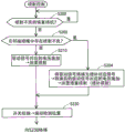
Fig. 11 is a flowchart showing a procedure of ejection control performed in association with detection of an ejection failure of ink.
Fig. 12 is a flowchart showing a procedure of ejection control in the liquid ejecting apparatus according to the second embodiment.
Fig. 13 is a flowchart showing the procedure of the first half of the ejection failure re-determination control in the liquid ejecting apparatus according to the third embodiment.
Fig. 14 is a flowchart showing the procedure of the second half of the ejection failure re-determination control in the liquid ejecting apparatus according to the third embodiment.
Fig. 15 is a flowchart showing a procedure of recovery control of ejection failure in the liquid ejecting apparatus according to the third embodiment.
Fig. 16 is a flowchart showing a procedure of the ink ejection failure occurrence notification control in the liquid ejecting apparatus according to the fourth embodiment.
Fig. 17 is an explanatory diagram showing an example of notification of ink ejection.
Fig. 18 is a flowchart showing a procedure of the ink ejection failure occurrence notification control in the liquid ejection device according to the fifth embodiment.
Fig. 19 is an explanatory diagram showing, by contrast, a case of ejection in a normal state of a medium after completion of printing and an ejection case in an ejection path in an abnormal state.
Detailed Description
A. The first embodiment:
a-1. the device comprises:
fig. 1 is an explanatory diagram schematically showing a configuration of a liquid ejecting apparatus 100 according to a first embodiment of the present invention. The liquid ejecting apparatus 100 is an ink jet type printing apparatus that ejects droplets of ink, which is an example of a liquid, onto the medium 12. Hereinafter, the ejection of the droplets of the ink is simply referred to as ink ejection. The liquid ejecting apparatus 100 uses a printing target made of any material such as a resin film or a cloth as the medium 12 in addition to the printing paper. The liquid ejecting apparatus 100 prints on various media 12 based on print data input from a print data transmitting device GM such as a Personal Computer (PC) or a Digital Camera (DC), for example. The X direction shown in each of fig. 1 and later is a transport direction (main scanning direction) of a liquid ejecting head 26 described later, the Y direction is a medium feeding direction (sub-scanning direction) orthogonal to the main scanning direction, and the Z direction is an ink ejecting direction orthogonal to the XY plane. In the following description, the main scanning direction is referred to as a printing direction as appropriate for convenience of description. When the direction is specified, the direction of the drawing is set to + and a plus or minus sign is used in the direction symbol.
The liquid ejecting apparatus 100 includes: a liquid container 14, a transport mechanism 22 for sending out the medium 12, a control unit 200, a head moving mechanism 24, a liquid ejecting head 26 corresponding to a printing head, a first recovery mechanism 110, and a second recovery mechanism 120. The first recovery mechanism 110 and the second recovery mechanism 120 are disposed outside the liquid ejection area with respect to the medium 12, that is, outside the ink ejection area, and are used to recover from an ink ejection failure from the nozzle N, as will be described later.
The liquid container 14 stores a plurality of kinds of ink ejected from the liquid ejection head 26 individually. As the liquid container 14, a bag-shaped ink pack formed of a flexible film, an ink tank capable of replenishing ink, or the like can be used.
The control Unit 200 includes a Processing circuit such as a CPU (Central Processing Unit) or an FPGA (Field Programmable Gate Array) and a memory circuit such as a semiconductor memory, and collectively controls the transport mechanism 22, the head moving mechanism 24, the liquid ejecting head 26, and the like. The control unit 200 corresponds to a control unit in the present invention, and performs ink ejection from the nozzles N, ink supply from the liquid 14, and various text display and image display on a display device GD such as a liquid crystal display, which will be described later, based on print data input from the print data transmitting device GM. Various controls and device configurations that the control unit 200 performs in association with the ejection or supply of ink will be described later.
The transport mechanisms 22 each include a motor 22M, and feed the medium 12 in the + Y direction by motor driving based on a control signal from a motor driver (not shown) included in the control unit 200. The transport mechanism 22 also corresponds to the discharge mechanism of the present invention that discharges the medium 12 outside the ink ejection area. The structure of the control unit related to ink ejection will be described later.
The head moving mechanism 24 includes: a conveyor belt 23 that extends in the X direction across the printing range of the medium 12, a carriage 25 that houses the liquid ejecting head 26 and is fixed to the conveyor belt 23, and a motor 23M for driving the belt. The head moving mechanism 24 reciprocates the liquid ejecting head 26 together with the carriage 25 in the main scanning direction (X direction) by forward and reverse rotation driving of the motor 23M based on a control signal from a motor driver (not shown) included in the control unit 200. The carriage 25 reciprocates while being guided in the main scanning direction by a guide rail 27. Note that, the head structure of the plurality of liquid ejecting heads 26 may be mounted on the carriage 25 for the type of ink stored in the liquid container 14, or the head structure may be mounted on the carriage 25 together with the liquid container 14 and the liquid ejecting head 26.
Under the control of the control unit 200, the liquid ejection head 26 ejects the ink supplied from the liquid container 14 toward the medium 12 from the plurality of nozzles N. The ink is ejected from the nozzles N during the reciprocating movement of the liquid ejecting head 26, and a desired image or the like is printed on the medium 12. As shown in fig. 1, the liquid ejecting head 26 includes a nozzle row in which a plurality of nozzles N are arranged in the sub-scanning direction, and two rows of the nozzle row are provided at predetermined intervals in the main scanning direction. The two nozzle rows are shown in the drawing as a first nozzle row L1 and a second nozzle row L2, and the nozzles N of the first nozzle row L1 and the nozzles N of the second nozzle row L2 are arranged in a row in the main scanning direction. In the following description, for convenience of explanation, the center of the first nozzle row L1 and the second nozzle row L2 is defined as a central axis, and a YZ plane including the central axis and passing through the center in the Y direction is defined as a central plane O. The nozzles N in the first nozzle row L1 and the second nozzle row L2 may be arranged in a staggered manner with a shift in the medium feeding direction (Y direction). The first nozzle row L1 and the second nozzle row L2 are nozzle rows that match the plurality of types of ink included in the liquid container 14, but are not shown.
The liquid jet head 26 having the first nozzle row L1 and the second nozzle row L2 is a laminated body in which head components are laminated. Fig. 2 is an explanatory diagram illustrating a main head member of the liquid ejecting head 26 in an exploded view. Fig. 3 is an explanatory diagram showing the liquid ejecting head 26 in a cross-sectional view along the line 3-3 in fig. 2. The thickness of each illustrated component does not represent the actual structural thickness. In fig. 2, for convenience of illustration, a part of the first flow channel substrate 32 as a structural member is omitted.
As shown in the drawing, the liquid ejecting head 26 includes a structure related to the nozzles N of the first nozzle row L1 and a structure related to the nozzles N of the second nozzle row L2 so as to be plane-symmetric with respect to the center plane O. That is, in the liquid ejecting head 26, the structure of the + X direction side first portion P1 and the-X direction side second portion P2 are common across the center plane O. The nozzles N in the first nozzle row L1 belong to the first portion P1, the nozzles N in the second nozzle row L2 belong to the second portion P2, and the center plane O is a boundary surface between the first portion P1 and the second portion P2.
The liquid ejecting head 26 includes, as main head components, a flow path forming portion 30 that contributes to the formation of a flow path in the head, and a housing portion 48 that contributes to the supply and discharge of ink. The flow channel forming part 30 is configured to laminate a first flow channel substrate 32 and a second flow channel substrate 34. The two substrates, i.e., the first flow channel substrate 32 and the second flow channel substrate 34, are plate bodies elongated in the Y direction, and the second flow channel substrate 34 is fixed to the upper surface Fa in the-Z direction of the first flow channel substrate 32 with an adhesive.
The first channel substrate 32 is provided with a vibration part 42, a plurality of piezoelectric elements 44, a protective member 46, and a housing part 48 on the upper surface Fa side. The vibrating portion 42 is a thin plate body that is long in the Y direction and is provided from the first portion P1 to the second portion P2. The protective member 46 is a plate body elongated in the Y direction and provided from the first portion P1 to the second portion P2. The protective member 46 forms a concave space on the upper surface side of the vibrating portion 42, and covers the vibrating portion 42. The housing portion 48 is a plate elongated in the Y direction. The housing 48 holds the protective members 46 on both sides of the center plane O on the second flow path substrate 34 of the flow path forming portion 30. Further, the nozzle plate 52 and the vibration absorber 54 are disposed on the lower surface Fb in the Z direction of the first channel substrate 32. The nozzle plate 52 and the vibration absorber 54 are each a plate body elongated in the Y direction. The nozzle plate 52 is disposed from the first portion P1 to the second portion P2. The vibration absorber 54 is provided separately for the first portion P1 and the second portion P2. These elements are bonded to the upper surface Fa or the lower surface Fb of the first flow channel substrate 32 with an adhesive.
As shown in fig. 2, the nozzle plate 52 includes two rows of circulation passages 72, each of which is formed by arranging the nozzles N of the first portion P1 and the nozzles N of the second portion P2 in a row, and is provided between the first nozzle row L1 of the first portion P1 in which the nozzles N are arranged and the second nozzle row L2 of the second portion P2 in which the nozzles N are arranged. Each nozzle N is a circular through-hole for ejecting ink. As shown in fig. 3, the circulation passage 72 is a sink groove formed on the surface of the nozzle plate 52. Also, the circulation passage 72 of the + X-direction column corresponds to the nozzle N in the first nozzle column L1, and the circulation passage 72 of the-X-direction corresponds to the nozzle N in the second nozzle column L2. Nozzle plate 52 is formed to have nozzles N and circulation passages 72 as shown in fig. 3 by applying a semiconductor manufacturing technique, such as dry etching or wet etching, to a single crystal substrate of silicon (Si). The ink ejection from the nozzles N and the ink recovery using the circulation path 72 will be described later.
The vibration absorber 54 forms the bottom surface of the liquid ejecting head 26 together with the nozzle plate 52, and closes the ink inflow chamber Ra, the liquid supply chamber 60, and the supply passage 61 by adhesion to the lower surface Fb of the first flow path substrate 32. The vibration absorber 54 is formed of a flexible film, for example, a plastic substrate, which absorbs pressure fluctuations in the ink inflow chamber Ra.
The first flow channel substrate 32 as an object of adhesion of the nozzle plate 52 and the vibration absorber 54 corresponds to the first portion P1 and the second portion P2 so as to form the ink inflow chamber Ra, the liquid supply chamber 60, the supply passage 61, the communication passage 63, and the liquid discharge chamber 65 is formed in common in the first portion P1 and the second portion P2. As shown in fig. 2, the ink inflow chamber Ra is an elongated through opening extending in the Y direction, and is commonly used for ink supply to each of the nozzles N in the first nozzle row L1 and each of the nozzles N in the second nozzle row L2. The supply passage 61 and the communication passage 63 are through holes formed for each of the nozzles N of the first nozzle row L1 and the second nozzle row L2. As shown in fig. 3, the supply liquid chamber 60 is formed by a long sink groove formed on the lower surface Fb of the first flow path substrate 32 so as to be juxtaposed to the ink inflow chamber Ra along the Y direction, and is blocked together with the ink inflow chamber Ra and the supply channel 61 by adhesion of the vibration absorber 54 to the lower surface Fb of the first flow path substrate 32. This liquid supply chamber 60 is associated with ink supply from the ink inflow chamber Ra to the supply channel 61 for each nozzle N.
As shown in fig. 2, the discharge liquid chamber 65 is formed in such a manner that a sink groove formed in an elongated shape along the Y direction is formed on the lower surface Fb of the first flow channel substrate 32, and is closed together with the communication channel 63 by adhesion of the nozzle plate 52 to the lower surface Fb of the first flow channel substrate 32. The nozzle plate 52 includes: the nozzles N of the first nozzle row L1 and the second nozzle row L2, and the circulation path 72 corresponding to the respective nozzles N of each nozzle row. Each nozzle N is disposed at a position overlapping the communication passage 63 in a plan view in the Z direction. The circulation channel 72 is disposed at a position overlapping the partition wall 66 that partitions the communication channel 63 and the discharge liquid chamber 65 for each nozzle row in a plan view in the Z direction. The circulation channel 72 serves as an ink flow path across the partition wall 69 by the adhesion of the nozzle plate 52 to the lower surface Fb of the first flow path substrate 32, and communicates the communication channel 63 of each nozzle N with the discharge liquid chamber 65. The discharge liquid chamber 65 receives the inflow of the ink from the communication channel 63 of each nozzle N through the communication by the circulation channel 72, and participates in the ink recovery.
As shown in fig. 2, the discharge liquid chamber 65 is a sunken groove longer than the arrangement of the nozzles N in the first nozzle row L1 and the second nozzle row L2, and has ink discharge ports 65a and 65b at both ends of the groove. The ink discharge ports 65a and 65b are through holes penetrating the bottom wall of the discharge liquid chamber 65 of the sink, that is, the first channel substrate 32, and are connected to circulation pipes in a circulation mechanism 75 described later. After the ink flows into the communication channel 63, it enters the discharge liquid chamber 65 through the circulation channel 72, and is discharged from the liquid ejecting head 26 through the ink discharge ports 65a, 65b of the discharge liquid chamber 65. Since the ink discharged in this manner enters the pressure chamber C as described later, a circulation flow path for the ink is formed by the circulation passage 72 and the discharge liquid chamber 65 downstream of the communication passage 63.
The second flow channel substrate 34 bonded to the upper surface Fa of the first flow channel substrate 32 forms a pressure chamber C corresponding to the first and second portions P1 and P2. The pressure chamber C is a through hole along the X direction formed for each of the nozzles N of the first nozzle row L1 and the second nozzle row L2, and communicates with the supply passage 61 and the communication passage 63 of the first flow path substrate 32 at the lower end side of the through hole in the + Z direction. The pressure chamber C is closed at the upper end side of the through hole in the-Z direction by the vibrating portion 42 sandwiched by the protective member 46. The pressure chamber C sealed in this manner functions as a chamber for each of the nozzles N of the first nozzle row L1 and the second nozzle row L2. The first flow channel substrate 32 and the second flow channel substrate 34 are formed by applying the semiconductor manufacturing technique described above to a single crystal substrate of silicon, as in the nozzle plate 52.
The vibrating portion 42 sandwiched between the second flow channel substrate 34 and the protective member 46 is a plate-shaped member that can elastically vibrate, and includes a piezoelectric element 44 for each pressure chamber C that is closed as described above. Therefore, each piezoelectric element 44 individually corresponds to the nozzles N of the first nozzle row L1 and the second nozzle row L2. The piezoelectric element 44 corresponds to a pressure generating portion in the present invention. Fig. 4 is an explanatory diagram schematically showing a schematic configuration of the piezoelectric element 44. The piezoelectric element 44 is an element that deforms upon receiving a drive signal from the control unit 200, and is disposed on the vibrating portion 42 in accordance with the arrangement of the nozzles N. The piezoelectric element 44 of each nozzle extends in the X direction in such a manner as to overlap the pressure chamber C. Each piezoelectric element 44 is a laminated structure in which the second electrode 442 is laminated on the first electrode 441 bonded to the vibrating portion 42 with the insulating piezoelectric layer 443 interposed therebetween. The first electrode 441 is grounded, and the second electrode 442 is applied with a voltage that individually corresponds to a series of liquid ejection requests from the control unit 200, in this embodiment, a series of printing requests necessary for printing the entire area of printing. By applying such a voltage, the piezoelectric element 44 is deflected in the Z direction to cause vibration in the Z direction, thereby generating a pressure change in the ink supplied to the pressure chamber C, specifically, the ink passing through the pressure chamber C. This pressure change reaches the nozzle N through the communication passage 63. The first electrode 441 may be an electrode common to the piezoelectric elements 44 included in the first nozzle row L1 and an electrode common to the piezoelectric elements 44 included in the second nozzle row L2.
The piezoelectric element 44 vibrates by receiving residual vibration caused by the ink in the pressure chamber C during a period from when the piezoelectric element receives the vibration by receiving the voltage application to when the piezoelectric element receives the voltage application at the drive timing corresponding to the next print request. Since the piezoelectric element 44 is not subjected to voltage application during this period, it functions as an electrostatic actuator in which the first electrode 441 and the second electrode 442, which are good conductors, face each other with the insulating piezoelectric layer 443 interposed therebetween. Therefore, the piezoelectric element 44 causes an increase or decrease in the capacitance according to the flexural vibration of the piezoelectric element itself during the period in which the residual vibration of the ink causes flexural vibration in the Z direction. By inputting this change in capacitance to an oscillation circuit described later, it is possible to detect the change in vibration of the residual vibration generated in the ink in the pressure chamber C. This will be described later.
The protective member 46 is a plate-like member for protecting the piezoelectric elements 44 of the respective pressure chambers C, and is sandwiched between the first channel substrate 32 and the housing 48 in a state where the vibrating portion 42 is sandwiched between the second channel substrate 34 and the protective member. The protective member 46 may be formed of other materials, as in the first flow channel substrate 32 or the second flow channel substrate 34, in addition to being formed by applying the semiconductor manufacturing technique described above to a single crystal substrate of silicon. The housing portion 48 covers the upper surface side of the liquid ejecting head 26, and contributes to the protection of the entire head, the storage of ink supplied to the pressure chambers C of the respective nozzles N, and the replenishment of ink from the liquid container 14 (see fig. 1). That is, the housing portion 48 includes the upstream ink inflow chamber Rb overlapping the ink inflow chamber Ra of the first channel substrate 32 in the Z direction, and the ink storage chamber (reservoir R) as the common liquid chamber is formed by the upstream ink inflow chamber Rb and the ink inflow chamber Ra of the first channel substrate 32. The ink supply to the upstream ink inflow chamber Rb is completed from the ink introduction port 49 of the inflow chamber top wall. The housing portion 48 is formed by injection molding of an appropriate resin material.
Fig. 5 is an explanatory diagram showing ink supply paths to the nozzles N and paths through which ink circulates so that various flow path forming portions such as the supply path 61 in the liquid ejecting head 26 overlap. In fig. 5, the various flow channel forming portions of the liquid ejecting head 26 are shown to overlap when viewed from the + Z-axis direction. In fig. 5, the locus of the supply pipe 16 from the liquid container 14 to the ink introduction port 49 and the locus of the supply pipe from the discharge liquid chamber 65 to the recovery pipe 78 via the circulation mechanism 75 described later include the arrangement positions of the liquid container 14 and the circulation mechanism 75, and are schematically illustrated. The line 3-3 shown in fig. 5 represents the cross-sectional view of fig. 3 corresponding to the line 3-3 shown in fig. 2.
As shown in the drawing, the reservoir R constituted by the ink inflow chamber Ra and the supply liquid chamber 60 (refer to fig. 3) in the first flow path substrate 32 extends in the Y direction along each of the first and second nozzle arrays L1 and L2, and in the first portion P1, overlaps the supply channel 61 of each nozzle corresponding to the respective nozzle N in the first nozzle array L1. In addition, the reservoir R overlaps the supply passages 61 corresponding to the respective nozzles N in the second nozzle row L2 in the second portion P2. The supply passage 61 of each nozzle row overlaps with the pressure chamber C of each nozzle, which overlaps with the communication passage 63 of each nozzle row. The communication passage 63 of the first flow channel substrate 32 overlaps with the nozzle N of the nozzle plate 52 shown in fig. 3. Therefore, the ink is supplied from the liquid container 14 to the reservoir R through the supply pipe 16 connected to the ink introduction port 49 by the pump 15.
The ink stored in the reservoir R by receiving the pressure of the pump 15 is supplied to the communication path 63 through the supply path 61 and the pressure chamber C, and is ejected from the nozzle N by receiving the vibration of the piezoelectric element 44 driven and controlled by the control unit 200 by the pressure chamber C. The ink supply from the liquid container 14 is continued not only in a printing situation where the ink is being ejected from the nozzles N but also in a situation where a failure detection of ink ejection described later is not accompanied by ink ejection from the nozzles N.
As the ink is ejected from the nozzles N, the reservoir R is replenished with ink from the liquid container 14 and/or the circulation mechanism 75 through the ink introduction port 49. The circulation mechanism 75 includes an ink storage tank 76 and a pressure adjusting unit 77 that adjusts the pressure in the storage tank to a lower pressure than the pressure-feed pressure of the pump 15. The circulation mechanism 75 receives circulating ink described later from the discharge chamber 65 from the ink discharge port 65a and the ink discharge port 65b, stores the received circulating ink in the ink storage tank 76, and then circulates the ink in the reservoir R through the ink introduction port 49. The circulation of the circulating ink through the ink introduction port 49 to the reservoir R is realized by the pressure adjustment of the pressure adjusting section 77 with respect to the pressure feeding pressure of the pump 15, which will be described later.
The discharge liquid chamber 65 extends in the Y direction between the first nozzle row L1 and the second nozzle row L2, and includes an ink discharge port 65a in the + Y direction with respect to the lowermost nozzle N in the + Y direction in each nozzle row, and an ink discharge port 65b in the-Y direction with respect to the uppermost nozzle N in the-Y direction in each nozzle row. In addition, the discharge liquid chamber 65 overlaps the circulation passages 72 corresponding to the respective nozzles N in the first nozzle row L1 in the first portion P1, and overlaps the circulation passages 72 corresponding to the respective nozzles N in the second nozzle row L2 in the second portion P2. Therefore, in a state where the ink supply to the pressure chamber C is continued, the ink exceeding the sum of the internal volumes of the pressure chamber C and the communication channel 63 is pushed out to the discharge liquid chamber 65 through the communication channel 63 and the circulation channel 72, reaches the circulation mechanism 75 as the circulation ink through the ink discharge ports 65a and 65b, and circulates in the reservoir R by the circulation mechanism 75.
Fig. 6 is a block diagram showing a main electrical configuration related to ink ejection from the nozzles N so as to correspond to the piezoelectric elements 44 in the respective pressure chambers C. Fig. 7 is a block diagram showing a correlation between the main electrical structure associated with ink ejection from the nozzles N and the structure of the piezoelectric element 44. In fig. 7, the thickness of the structural elements is exaggerated to show the stacking of the structural elements of the piezoelectric element 44.
As shown in fig. 6, the control unit 200 receives an input of print data from the print data transmission apparatus GM via an interface 201 (IF in the drawing), and outputs a display signal such as a text to the display apparatus GD via the interface 201. The control unit 200 includes various functional units such as an ink supply unit 212, a data conversion output unit 210, a switching signal output unit 215, an ejection failure determination unit 220, and an ejection failure storage unit 230 so as to be connected to each other via a system bus in association with ink ejection. These functional units are configured by executing a predetermined program stored in a memory, and the ink supply unit 212 realizes a cyclic ink supply to the pressure chambers C. The data conversion output section 210 converts the print data (a series of print requests) received from the print data transmitting device GM into voltage application data to the piezoelectric elements 44 for ink ejection from the respective nozzles N of the first nozzle row L1 and the second nozzle row L2, and applies a voltage to the piezoelectric elements 44 for the respective nozzles N by the converted voltage application data. The switching signal output unit 215 generates a signal for switching the piezoelectric element 44 to a detection purpose of the vibration transition of the residual vibration caused by the ink in the pressure chamber C after the ink ejection and a signal for switching the signal to the opposite direction according to the purpose of the ink ejection, and outputs the switching signal to the switch 150 described later. The ejection failure determination unit 220 determines the presence or absence of a failure in liquid ejection from the nozzle N by the vibration transition of the residual vibration of the pressure chamber C obtained via the piezoelectric element 44 and the residual vibration detection device 300 described later. The ejection failure storage unit 230 stores the determination result of the ejection failure determination unit 220.
The liquid ejecting apparatus 100 has a residual vibration detection device 300 in association with detection of ink ejection failure. The residual vibration detection device 300 includes: an oscillation circuit 310, a voltage-frequency conversion circuit 320 (in the figure, an F/V conversion circuit) that realizes voltage-frequency conversion, and a waveform shaping circuit 330. As shown in fig. 7, the oscillation circuit 310 is connected to the switch 150 corresponding to each piezoelectric element 44. The switcher 150 switches the connection point of the second electrode 442 in the piezoelectric element 44 to any one of the application position Vp and the vibration detection position Sp by the switching signal from the switching signal output section 215. In the oscillation circuit 310, when the connection point of the second electrode 442 of the piezoelectric element 44 is switched to the vibration detection position Sp of the oscillation circuit 310, an increase or decrease change in capacitance according to the flexural vibration of the piezoelectric element 44 is input, and oscillation is performed in accordance with the increase or decrease in the input capacitance. Such oscillation may be generated, for example, in a CR oscillation circuit using a schmitt-trigger inverter having hysteresis characteristics together with a capacitor (C) and a resistor (R). The voltage-frequency conversion circuit 320 is configured by using several switching elements, capacitors, resistance elements, and a constant current source, and performs voltage-frequency conversion on the oscillation waveform (residual oscillation waveform) output from the oscillation circuit 310. The waveform shaping circuit 330 is configured by a capacitor for removing a dc component, several resistance elements, a dc voltage source, an amplifier, and a comparator, converts the residual vibration waveform subjected to the voltage-frequency conversion by the voltage-frequency conversion circuit 320 into a rectangular wave, and outputs the rectangular wave to the ejection failure determination unit 220 of the control unit 200.
The liquid ejecting apparatus 100 according to the present embodiment assumes that a situation in which an ink ejection failure occurs from the nozzles N is: a situation in which bubbles of a size that may cause ink ejection failure remain in the pressure chamber C, a situation in which foreign matter of a size that may cause ink ejection failure remains in the pressure chamber C, and a situation in which foreign matter such as a paper sheet that may cause ink ejection failure blocks the opening area of the nozzle N. The residual vibration transition of the ink in the pressure chamber C in the state where the air bubbles remain, the residual vibration transition of the ink in the pressure chamber C in the state where the foreign matter remains, and the residual vibration transition of the pressure chamber C in the state where the opening is closed by the foreign matter have been known through experiments or the like in advance. The control unit 200 stores the transition and the cycle of the residual vibration waveform in each situation, which have been grasped, in the memory in the unit or the external memory in association with the cause of the ink ejection failure. Further, even if the ejection failure is caused by the increase in the viscosity of the ink, the transition and the period of the residual vibration waveform may be stored.
Fig. 8 is an explanatory diagram schematically showing recovery of ink ejection failure by the first recovery mechanism 110 provided outside the printing area of the medium 12. As shown, the first restoring mechanism 110 includes a wiping member 114 protruding from the main body 112. The wiping member 114 is a brush structure using a flexible rubber member or wire, and performs wiping for recovery from ejection failure. The first recovery mechanism 110 is usually located on the + Z direction side with respect to the liquid ejection head 26. The control unit 200 raises the first recovery mechanism 110 and causes the wiping member 114 to protrude further than the nozzle plate 52 in the liquid ejection head 26 in a condition where the ink ejection failure should be recovered by wiping. In this case, the wiping member 114 itself may be raised in the-Z direction, or the entire first restoring mechanism 110 may be raised. The control unit 200 moves the liquid ejecting head 26 in the-X direction in a state where the wiping member 114 protrudes beyond the nozzle plate 52 by a protrusion length Ts. Thus, the wiping member 114 wipes the lower surface of the nozzle plate 52 while being deflected as shown in the drawing, and foreign substances such as paper pieces adhering to the lower surface of the nozzle plate 52 and blocking the openings of the nozzles N (see fig. 3) are removed. Further, the foreign matter removal by the first recovery mechanism 110 may be performed while the liquid ejecting head 26 is reciprocated in the X direction. The first recovery mechanism 110 for recovering the ejection failure of the ink from the nozzles N by the wiping with the wiping member 114 corresponds to a recovery portion in the present invention.
Fig. 9 is an explanatory diagram schematically showing recovery of ink ejection failure by the second recovery mechanism 120 provided outside the printing area of the medium 12. As shown in the figure, the second recovery mechanism 120 is provided such that an ink absorbing material 122 is housed in an open container 121, and an ink discharge tube 123 is connected to the bottom wall of the open container 121 for the purpose of suction inside the container and discharge of the ink absorbed by the ink absorbing material 122. The ink absorbing material 122 is formed of a nonwoven fabric or sponge, and absorbs and holds the ink ejected from the nozzles N. The second recovery mechanism 120 sucks (pumps) the inside of the open container 121 or discharges the ink absorbed and held by the ink absorbing material 122 by a suction pump (not shown) via an ink discharge tube 123 connected to the bottom wall of the open container 121.
The second recovery mechanism 120 is usually located on the + Z direction side with respect to the liquid ejection head 26. The control unit 200 moves the liquid ejection head 26 out of the printing area and stops in a condition where the ink ejection failure should be recovered by pumping or flushing. Thereafter, the control unit 200 raises the open container 121 of the second recovery mechanism 120, and covers the entire nozzles N of the first nozzle row L1 and the second nozzle row L2 in the nozzle plate 52 in an airtight manner with the openings of the open container 121 (see fig. 5). When pumping, the control unit 200 sucks the inside of the open container 121 while realizing ink supply to the pressure chambers C of the liquid ejecting head 26. By this pumping, bubbles or foreign substances remaining in the pressure chamber C or the communication channel 63 downstream thereof, which cause ink ejection failure, are carried out by the ink flowing through the pressure chamber C. At this time, the piezoelectric element 44 of the pressure chamber C may be driven. At the time of flushing, the control unit 200 drives the piezoelectric elements 44 of the pressure chambers C so that a larger amount of ink than the ink ejection amount at the time of printing is ejected while supplying ink to the pressure chambers C of the liquid ejecting head 26 without sucking the open container 121. By this flushing, bubbles or foreign matter remaining in the pressure chamber C or the communication channel 63 downstream thereof and causing ink ejection failure is carried out by the ink flowing through the pressure chamber C. The second recovery mechanism 120 for recovering the ejection failure of the ink from the nozzles N by pumping or flushing also corresponds to the recovery portion in the present invention.
A-2. injection-related control:
fig. 10 is a flowchart showing a procedure for realizing the supply control of the ink to the liquid ejecting head 26. This supply control is repeatedly executed by the ink supply unit 212 of the control unit 200 while printing is performed by the liquid ejecting apparatus 100. In the ink supply unit 212, first, the ink supply system from the liquid container 14 to the liquid ejecting head 26, specifically, the pump 15 of the supply pipe 16 is driven by a predetermined pumping pressure, and the pressure of the pressure adjusting unit 77 in the circulation mechanism 75 is adjusted (step S100). Thereby, the ink is supplied to each pressure chamber C through the reservoir R, the liquid supply chamber 60, and the liquid supply passage 61, and the ink having passed through the pressure chamber C is collected into the circulation mechanism 75 through the communication passage 63, the circulation passage 72, and the liquid discharge chamber 65.
Next, the ink supply unit 212 determines whether or not printing in accordance with a series of printing requests received and transmitted from the print data transmission device GM is completed (step S110), and continues to supply and collect ink to the pressure chambers C until the printing is completed. On the other hand, when it is determined that printing is finished, the ink supply unit 212 stops the pump 15 and also stops the pressure regulation by the pressure regulating unit 77 (step S120), and the supply control routine is finished. By this supply control, the supply of ink to the plurality of pressure chambers C and the recovery of ink that has passed through the pressure chambers C are continued during a period in which there is a series of printing requests to eject ink from the nozzles N. Therefore, the supply control and the ink supply portion 212 for executing the control constitute a liquid supply portion in the present invention together with the liquid container 14 and the circulation mechanism 75. In addition, the ink supply portion 212 may temporarily stop the ink supply. For example, if the user cancels printing, the ink supply unit 212 temporarily stops ink supply and resumes ink supply and recovery in response to an instruction to cancel cleaning or restart printing. Further, if the ink supply is not necessary as in wiping for recovery from defective ejection of ink, the ink supply may be temporarily stopped during the wiping period, and the ink supply and recovery may be recovered by completion of wiping. Further, wiping can also be performed under ink supply.
Fig. 11 is a flowchart showing a procedure of ejection control performed in association with detection of an ejection failure of ink. The ejection control is continuously executed by the control unit 200 while the printing by the liquid ejecting apparatus 100 is performed, along with the output of the print data by the data conversion output section 210, the switching of the switch 150 by the switching signal output section 215, the ejection failure determination by the ejection failure determination section 220, and the waveform shaping in the residual vibration detecting device 300. The ejection control is performed individually for each piezoelectric element 44, with the piezoelectric element 44 in the pressure chamber C of each of the first nozzle row L1 and the second nozzle row L2 being the control target. Before the start of the injection control, the switch 150 is switched by the switching signal output unit 215 to the application position Vp at which the voltage is applied to the piezoelectric element 44 in each pressure chamber C. That is, the initial state of the switch 150 is the application position Vp.
First, the control unit 200 determines whether or not the current time point is a recovery standby state in which an ejection failure accompanied by a temporary stop of ink ejection is caused in step S290 (step S200). In the liquid ejecting apparatus 100 according to the present embodiment, when an ejection failure occurs in a certain nozzle N in a process described later in ejection control, ink supply and recovery to the nozzle N are continued after ink ejection is temporarily stopped for the nozzle N, and ink ejection is performed from the other nozzle N by driving the piezoelectric element 44 after ink supply and recovery are continued for the other nozzle N. Therefore, in the following description, the ejection control procedure will be described assuming that the state in which no defect is present in ink ejection is changed to the ejection defect in the nozzle N to be subjected to the ejection control. The nozzle N to be subjected to the ejection control is simply referred to as "control target nozzle N".
If there is no ejection failure in the control target nozzle N, the control unit 200 determines that the ejection failure is not on standby in the determination of the standby for recovery of the ejection failure in step S200, and then proceeds to the voltage application in step S210. The voltage application in step S210 is realized by using, as the drive signal, voltage print data in which the data conversion output unit 210 converts the print data for the ejection of ink from the control target nozzle N. Specifically, at the execution time point of step S210, if the control target nozzle N is the nozzle N that does not eject ink, the data conversion output unit 210 sets the voltage application data of the piezoelectric element 44 to the blank data that does not require driving, and therefore, at step S210, ink ejection does not occur in the control target nozzle N. On the other hand, if the nozzle N to be controlled is a nozzle N requiring ink ejection, the data conversion output unit 210 sets the voltage application data of the piezoelectric element 44 as a drive signal requiring driving, and therefore in step S210, voltage application is performed to the piezoelectric element 44 of the nozzle N to be controlled, and ink ejection is performed from the nozzle N to be controlled.
After the ink ejection from the control target nozzle N, the control unit 200 outputs the switching signal of the switch from the switching signal output unit 215 to the switcher 150, and switches the switcher 150 from the application position Vp to the oscillation detection position Sp (step S220). Since the change in the increase or decrease in the capacitance according to the flexural vibration of the piezoelectric element 44 is input from the second electrode 442 to the oscillation circuit 310 by the switching of the switch, the control unit 200 detects the vibration transition of the residual vibration generated in the ink in the pressure chamber C corresponding to the nozzle N to be controlled, based on the pressure change accompanying the driving of the piezoelectric element 44 in step S210 (step S230). In the detection of the transition of the residual vibration, a residual vibration waveform corresponding to an increase and decrease change in capacitance received from the second electrode 442 is obtained as an oscillation waveform by the oscillation circuit 310, and voltage-frequency conversion is performed on the oscillation waveform by the voltage-frequency conversion circuit 320. After that, the oscillation waveform (residual oscillation waveform) subjected to the voltage-frequency conversion by the voltage-frequency conversion circuit 320 is converted into a rectangular wave.
After the detection of the transition of the residual vibration in step S230, the control unit 200 receives the rectangular wave converted by the voltage-frequency conversion circuit 320 by the ejection failure determination unit 220 through waveform shaping in the waveform shaping circuit 330, and performs rectangular wave frequency measurement as waveform measurement by the ejection failure determination unit 220 (step S240). As described above, in the liquid ejecting apparatus 100 according to the present embodiment, the ink ejection failure from the nozzle N is caused by the remaining of air bubbles or foreign matter in the pressure chamber C, or the nozzle clogging due to foreign matter such as paper pieces, and the transition, the cycle, the frequency, the attenuation ratio, and the like of the residual vibration waveform in the pressure chamber C under these conditions are stored in the memory. Therefore, in the ejection failure determination in step S250 subsequent to step S240, the control unit 200 compares the cycle of the stored residual vibration waveform with the cycle of the residual vibration waveform at the current time point measured in step S240, and determines whether or not an ejection failure of ink has occurred in the control target nozzle N based on the comparison result (step S260). The ejection failure determination in step S260 is synonymous with the case where the vibration transition detected in step S230 is determined to be an ejection failure vibration transition corresponding to a failure in liquid ejection from the control target nozzle N. Therefore, the ejection control including the determination of the ejection failure in steps S250 to S260 constitutes an ejection failure determination section in the present invention together with the control unit 200 and the residual vibration detection device 300 that perform the control.
At the present time, since no ejection failure occurs in the control target nozzle N, the control unit 200 determines that no ejection failure exists in step S260, and switches the switcher 150 from the vibration detection position Sp to the application position Vp in the next step S270. In this way, the voltage application to the piezoelectric element 44 at the next ink ejection timing is not hindered.
Following the switching to the application position Vp, the control unit 200 determines whether printing in accordance with a series of printing requests received and transmitted from the print data transmission apparatus GM is finished (step S280). When determining that printing is completed, the control unit 200 ends the ejection control routine, and if printing is not completed, the control unit proceeds to step S200 and repeats the processing described above. Therefore, in a situation where the control target nozzle N is not determined to have an ejection failure in step S260, the ejection failure is detected at the ink ejection timing at which the predetermined drive signal is performed for each ink ejection of the control target nozzle N. That is, the detection of the vibration transition of the residual vibration generated in the ink in the pressure chamber C of the control target nozzle N in accordance with the pressure change accompanying the driving of the piezoelectric element 44 for ink ejection is performed with the period of the continuous ink ejection timing of the driving signal as the detection cycle.
On the other hand, if it is determined in step S260 that an ink ejection failure is present in the control target nozzle N due to residual air bubbles or the like in the pressure chamber C, the control unit 200 temporarily stops the ink ejection from the control target nozzle N (step S290). The pressure chamber C of the control target nozzle N determined in step S260 to have a defective ink ejection is the ejection defective pressure chamber in the present invention. The control target nozzle N determined in step S260 to have the ink ejection failure is the nozzle N corresponding to the ejection failure pressure chamber in the present invention. The process of step 290 of temporarily stopping the ink ejection from the control target nozzle N is synonymous with the case where the driving of the piezoelectric element 44 of the control target nozzle N is stopped by continuing at least a fixed stop period regardless of a series of printing requests. That is, the state in which the piezoelectric element 44 of the control target nozzle N is stopped from being driven by the processing of step S290 is when the driving of the piezoelectric element 44 is stopped. The temporary stop of the ink ejection from the nozzle N to be controlled is performed in association with the stop of the driving of the piezoelectric element 44 with respect to the pressure chamber C of the nozzle N to be controlled. In step S290, the control unit 200 temporarily stops the ink ejection over a fixed stop period of, for example, about 1 to 30 seconds. Hereinafter, the fixed stop period is referred to as a "temporary stop period". When it is determined in step S260 that there is an ejection failure, the control unit 200 stores the cause of the ejection failure, specifically, any one of the causes of the nozzle clogging due to the air bubbles remaining in the pressure chamber C, the foreign matter remaining in the pressure chamber C, or the foreign matter such as paper pieces, in the ejection failure storage unit 230 together with the nozzle data that can specify the control target nozzle N that causes the ejection failure. The stored result can be used when the recovery process is performed for the control target nozzle N in which the ejection failure has occurred.
After the temporary stop of the ink ejection, the control unit 200 notifies that the ejection failure has occurred in the control target nozzle N (step S292). The control unit 200 notifies the control target nozzle N that an ejection failure has occurred by causing the display device GD to display a text such as "ink ejection failure has occurred" or an image in which an ejection failure is recognized, or by performing blinking control on a warning lamp, not shown, provided in the liquid ejecting apparatus 100.
The control unit 200 proceeds to step S270 when the ejection failure notification is performed, and switches the switcher 150 from the vibration detection position Sp to the application position Vp. In this way, the voltage application to the piezoelectric element 44 at the ink ejection timing after the recovery standby of the ejection failure is not hindered.
After the ink ejection from the control target nozzle N is temporarily stopped for the ink ejection failure, the control unit 200 proceeds to step S200 after the printing incompletion determination in step S280 after step S270. In step S200 after the transition, a negative determination is continuously made over the above-described temporary stop period from the temporary stop of the injection from the control target nozzle N in step S290 in the previous injection control. Therefore, although the piezoelectric element 44 is not driven during the temporary stop period for the control target nozzle N having an ejection failure, the supply and recovery of the ink are continued in the pressure chamber C corresponding to the control target nozzle N by the supply control as shown in fig. 10. Therefore, the entrainment of bubbles or foreign substances by the ink passing through the pressure chamber C corresponding to the control target nozzle N during the temporary stop period can be expected, and the recovery of the ejection failure can also be expected.
On the other hand, when the temporary stop period has elapsed, since it is determined in step S200 that the ejection failure recovery standby has ended, the process from step S210 onward is repeated after the temporary stop period has elapsed, and the ink ejection from the control target nozzle N is resumed.
In the liquid ejecting apparatus 100 according to the first embodiment described above, the supply of ink to the pressure chambers C of the plurality of nozzles N and the recovery of ink that has passed through the pressure chambers C are continued by the supply control shown in fig. 10. In the liquid ejecting apparatus 100 according to the first embodiment, the ink is ejected from the nozzles N in accordance with the pressure change of the ink in the pressure chambers C caused by the piezoelectric elements 44 of the respective pressure chambers C in a state where the supply and the recovery of the ink to the respective pressure chambers C of the plurality of nozzles N are continued. In the liquid ejecting apparatus 100 according to the first embodiment, when an ink ejection failure occurs in the ink ejection condition (step S260), the ink ejection from the control target nozzle N in which the ink ejection failure occurs is stopped for the temporary stop time (step S290), and after the temporary stop time elapses, the ink ejection from the control target nozzle N in which the ink ejection failure occurs is restarted. Since the supply and recovery of the ink to and from the pressure chamber C of the control target nozzle N in which the ejection failure is caused continue even during the temporary stop period, bubbles or foreign substances entering the pressure chamber C can be carried away by the ink passing through the pressure chamber C during the temporary stop period. Thus, after the temporary stop period has elapsed, there is a possibility that the ejection failure is eliminated. The target of stopping the ink ejection is the control target nozzle N which is set to have an ejection failure, and the ink ejection is continued even during the temporary stop period by driving the piezoelectric element 44 in accordance with a series of printing requests in the other nozzles N. Therefore, according to the liquid ejecting apparatus 100 of the first embodiment, bubbles or foreign substances can be dealt with even without performing circulation in the reservoir in the Y direction or the like, and in addition, in the case where nozzles other than the control target nozzle are also performing ink ejection, bubbles or foreign substances can be removed from the control target nozzle and the bubbles can be extinguished.
The liquid ejecting apparatus 100 according to the first embodiment includes a first recovery mechanism 110 that performs wiping, and a second recovery mechanism 120 that can respond to pumping or flushing for recovering from an ink ejection failure. Therefore, when a discharge failure occurs in a plurality of nozzles N or a discharge failure occurs in a specific nozzle N during the repetition of the discharge control shown in fig. 11, the discharge failure can be reliably recovered by wiping by the first recovery means 110 or by pumping or flushing by the second recovery means 120. In the present embodiment, since the control target nozzles N causing the ejection failure are stored in association with the failure cause as described above, when flushing by the second recovery means 120, a larger amount of ink than the ink ejection amount at the time of printing is ejected (flushed) from the control target nozzles N only for the control target nozzles N causing the ejection failure, and the failure recovery can be achieved. Further, if the second recovery mechanism 120 is provided so as to be able to pump each nozzle N, even if pumping is performed by the second recovery mechanism 120, suction (pumping) can be performed only for the control target nozzle N in which ejection failure has occurred, and failure recovery can be achieved.
In the liquid ejecting apparatus 100 according to the first embodiment, when ink ejection from the control target nozzles N is temporarily stopped, a user is notified of the occurrence of an ejection failure in the control target nozzles N by text display or the like on the display device GD. Therefore, according to the liquid ejecting apparatus 100 of the first embodiment, it is possible for the user to recognize that quality degradation may occur in a printed image or the like obtained on the medium 12 by ink ejection from the liquid ejecting head 26.
In the liquid ejecting apparatus 100 according to the first embodiment, the piezoelectric elements 44 of the pressure chambers C are driven while the liquid ejecting head 26 is scanned in the main scanning direction with respect to the medium 12, and acceleration accompanying the scanning in the main scanning direction of the liquid ejecting head 26 is influenced on the pressure chambers C corresponding to the control target nozzles N in which the ejection failure has occurred. Therefore, according to the liquid ejecting apparatus 100 of the first embodiment, bubbles or foreign substances mixed in the ink in the pressure chambers C corresponding to the control target nozzles N causing the ejection failure can be moved toward the discharge liquid chamber 65 by the acceleration during the scanning, and therefore, early recovery of the control target nozzles N as the ejection failure nozzles can be expected.
B. Second embodiment:
fig. 12 is a flowchart showing a procedure of ejection control in the liquid ejecting apparatus according to the second embodiment. In the ejection control of the liquid ejecting apparatus according to the second embodiment, as in the liquid ejecting apparatus 100 according to the first embodiment, the piezoelectric elements 44 in the pressure chambers C of the first nozzle row L1 and the second nozzle row L2 are controlled in the printing state, and the ejection control is individually performed for each piezoelectric element 44.
In the ejection control of the liquid ejecting apparatus according to the second embodiment, the control unit 200 determines whether or not the ejection failure is a recovery standby state in which the ink ejection is temporarily stopped (step S200), and waits for the recovery of the ejection failure, similarly to the liquid ejecting apparatus 100 according to the first embodiment. Next, in the ejection control of the liquid ejecting apparatus according to the second embodiment, the control unit 200 determines whether or not the nozzle N adjacent to the control target nozzle N at the current time point, for example, if the control target nozzle N is the nozzle N belonging to the first nozzle row L1, the nozzle N belonging to the second nozzle row L2, that is, the nozzle N adjacent to the control target nozzle N in the main scanning direction, is determined as an ejection failure in the ejection control up to the current time point (step S202). The pressure chamber C for the adjacent nozzle N corresponds to an adjacent pressure chamber in the present invention. If it is determined that no ejection failure has occurred in the adjacent nozzle N, the control unit 200 proceeds to step S210 described above, and applies a voltage corresponding to the drive signal for the nozzle N to be controlled to the piezoelectric element 44 of the nozzle N to be controlled. After that, the control unit 200 executes the already described processing of step S220 and thereafter.
On the other hand, when it is determined in step S202 that an ejection failure is present in the adjacent nozzle N, the control unit 200 converts the drive signal originally corresponding to the nozzle N to be controlled into an additional corresponding signal that is added to increase the vibration of the piezoelectric element 44 (step S204). Thus, by adding the corresponding signal, a voltage added to the piezoelectric element 44 of the control target nozzle N is applied so that ink ejection is performed in a larger amount than the amount of ejected droplets of ink that should be ejected. As a result, the ink ejection from the control target nozzle N is increased to supplement the adjacent nozzle N in which the ink ejection is temporarily stopped due to the ejection failure. Subsequent to step S204, control section 200 executes the processing described after step S220. In the ejection failure determination in step S250 after step S204, the amplitude and frequency of the residual vibration are different because the pressure change of the piezoelectric element 44 that causes the incremental ejection in step S204 is large, and this point is considered. Specifically, as described above, it is only necessary to determine whether or not there is an injection failure by assuming and storing the residual vibration transition in the case where the additional injection is performed in advance, and comparing the residual vibration transition after the step S204 is performed with the stored result.
The ejection control according to the second embodiment is repeatedly performed until the printing is completed, as in the first embodiment. Therefore, the above-described additional ejection from the control target nozzle N is continued until the ejection failure in the adjacent nozzle N is recovered and the driving of the piezoelectric element 44 of the adjacent nozzle N is restarted by applying the original voltage thereto.
In the liquid ejecting apparatus according to the second embodiment described above, even if an ejection failure occurs in the nozzles N belonging to one of the first nozzle row L1 and the second nozzle row L2, an amount of ink which cannot be ejected from the nozzles N having the ejection failure is additionally ejected from the nozzles N adjacent to the nozzles N having the ejection failure in the main scanning direction. Therefore, according to the liquid ejecting apparatus of the second embodiment, it is possible to suppress a decrease in quality of a printed matter such as a print image printed on the medium 12.
C. The third embodiment:
fig. 13 is a flowchart showing the procedure of the first half of the ejection failure re-determination control in the liquid ejecting apparatus according to the third embodiment. Fig. 14 is a flowchart showing the procedure of the second half of the ejection failure re-determination control in the liquid ejecting apparatus according to the third embodiment. The re-determination control is control executed by the control unit 200 in accordance with switching of the switch 150 by the switching signal output unit 215, determination of an ejection failure by the ejection failure determination unit 220, and waveform shaping in the residual vibration detection device 300 while ink ejection from the nozzle N to be controlled is temporarily stopped due to an ejection failure occurring in the nozzle N. The re-determination control is executed to control the piezoelectric element 44 in the pressure chamber C of the control target nozzle N, which is determined to have an ejection failure in the described ejection control. Therefore, in the following description, the control target nozzle in the re-judgment control is referred to as "re-judgment target nozzle N". Before the start of the re-determination control, the switch 150 is switched to the application position for applying the voltage to the piezoelectric element 44 in the pressure chamber C by the switching signal output unit 215 in step S270 in the executed ejection control.
In the control unit 200, first, it is determined whether or not the ejection failure is caused to temporarily stop the ink ejection in step S290 of the executed ejection control (step S300), and if not, no processing is performed. If there is no ejection failure in the executed ejection control, the liquid ejection device 100 is not in a state of recovery from the ejection failure. Therefore, the re-determination control is executed for the first time by performing the injection control in which the injection failure is present and the injection is temporarily stopped.
When it is determined in step S300 that the injection failure recovery standby condition is present, the control unit 200 determines whether or not a re-determination period has elapsed (step S305), and stands by until the re-determination period has elapsed. The re-determination time zone defines an interval between the execution of various re-determination processes of the re-determination control repeatedly in a situation where an injection failure is present in the executed injection control. In the present embodiment, the re-determination time period is set to 1 to 40 seconds. The re-determination period is longer than a failure determination period in the ejection failure determination in the ejection control, that is, a detection period (detection cycle) of the ejection failure which is a period of continuous ink ejection timings according to the drive signal.
When the re-determination period has elapsed, the control unit 200 applies a non-ejection voltage that does not cause ink ejection to the piezoelectric elements 44 in the pressure chambers C of the re-determination target nozzle N (step S310). By applying the non-ejection voltage, a pressure change that does not cause ink ejection from the nozzle N to be re-evaluated is generated in the pressure chamber C of the nozzle N to be re-evaluated.
Following the application of the non-ejection voltage to the piezoelectric element 44 in the pressure chamber C of the nozzle N to be re-determined, the control unit 200 outputs a switching signal of the switch from the switching signal output portion 215 to the switcher 150, and switches the switcher 150 from the application position Vp to the vibration detection position Sp (step S315). Since the change in the increase or decrease in the capacitance corresponding to the flexural vibration of the piezoelectric element 44 by the application of the non-ejection voltage is input from the second electrode 442 to the oscillation circuit 310 by the switching of the switch, the control unit 200 detects the change in the vibration of the residual vibration generated in the ink in the pressure chamber C corresponding to the nozzle N to be re-evaluated based on the pressure change accompanying the driving of the piezoelectric element 44 in step S310 (step S320). In the transition detection of the residual vibration, a residual vibration waveform corresponding to an increase and decrease change in capacitance of the input received from the second electrode 442 is obtained as an oscillation waveform by the oscillation circuit 310, and voltage-frequency conversion is performed on the oscillation waveform by the voltage-frequency conversion circuit 320. After that, the oscillation waveform (residual oscillation waveform) subjected to the voltage-frequency conversion by the voltage-frequency conversion circuit 320 is converted into a rectangular wave.
After the detection of the transition of the residual vibration in step S320, the control unit 200 receives the rectangular wave converted by the voltage-frequency conversion circuit 320 by the ejection failure determination unit 220 through waveform formation in the waveform formation circuit 330, and performs rectangular wave frequency measurement as waveform measurement by the ejection failure determination unit 220 (step S325). The voltage application in step S310 causes residual vibration having an amplitude or a period different from the voltage application at the time of ink ejection, although the voltage application is performed at a non-ejection voltage at which ink ejection does not occur. Even if the residual vibration is caused by the application of the non-ejection voltage, the residual vibration is influenced and shifted by the remaining of the air bubbles or foreign matter in the pressure chamber C, the nozzle clogging due to the foreign matter such as paper pieces, and the like. Therefore, in the present embodiment, the transition or the cycle of the residual vibration waveform generated in the ink in the pressure chamber C under the application of the non-ejection voltage that does not cause the ink ejection is stored in the memory in advance in association with the cause of the ejection failure. In the ejection failure determination in step S330 subsequent to step S325, the control unit 200 compares the cycle of the stored residual vibration waveform with the cycle of the residual vibration waveform applied based on the non-ejection voltage measured in step S325, and determines (re-determines) whether or not the ejection failure of the ink is generated in the nozzle N to be re-determined based on the comparison result (step S335). As described above, the re-determination control including step S335 is executed after it is determined that the injection failure has occurred by the previous injection control. Therefore, the ejection failure determination in step S335 determines whether the ink ejection failure continues to exist in the pressure chamber C of the nozzle N to be re-determined or whether the ejection failure has recovered.
When it is determined in step S335 that there is no ejection failure in the nozzle N to be re-determined through detection of the transition of the residual vibration due to the non-ejection voltage application (step S320), that is, when the ejection failure has recovered, the control unit 200 cancels the temporary stop of the ejection performed in the ejection control (step S340). Thus, at the ink ejection timing after the current time point, the ink ejection from the control target nozzle N is restarted. The re-determination control for performing the temporary stop cancellation of the ejection, which is realized in step S340, is performed during a period in which the ink ejection from the control target nozzle N, which is determined to have the ejection failure, is temporarily stopped. Therefore, by releasing the temporary stop of the injection in step S340, the driving of the piezoelectric element 44 of the pressure chamber C of the control target nozzle N is restarted regardless of whether or not the predetermined temporary stop period has elapsed.
After the temporary stop of injection is released, the control unit 200 resets the injection failure number counter Fc indicating the number of times that the injection failure is determined to be present again in the present re-determination control (step S345). Thereafter, the control unit 200 switches the switcher 150 from the vibration detection position Sp to the application position Vp (step S350) and temporarily ends the redetermination control, as in the ejection control. By adopting this method, the voltage application to the piezoelectric element 44 at the ink ejection timing after the temporary stop of the ejection is released in step S340 is not hindered.
On the other hand, when it is determined in step S335 that the ejection failure continues in the pressure chamber C of the nozzle N to be re-determined, the control unit 200 increments the value of the ejection failure number counter Fc by 1 (step S355), shifts to the switching of the switch in step S350, and then once ends the re-determination control. The injection failure number counter Fc is incremented each time the continuation determination of the injection failure in step S335 is performed until either the reset in step S345 after the recovery determination of the injection failure in step S335 and the reset under the recovery control described later are performed. That is, the count value of the injection failure number counter Fc makes it possible to determine whether or not the injection failure continues several times and continuously during the repetition of the re-determination control for each re-determination period.
In the control unit 200, when it is determined in step S335 that the ejection failure continues, the cause of the ejection failure described above is stored in the ejection failure storage unit 230 together with the nozzle data that can specify the nozzle N to be re-determined that the ejection failure is again determined to continue, as in the case of the ejection control. This stored result can be used when the recovery processing is performed for the nozzle N to be re-determined, which is determined again as the continuation of the ejection failure.
Fig. 15 is a flowchart showing a procedure of recovery control of ejection failure in the liquid ejecting apparatus according to the third embodiment. The recovery control is executed while the timing of execution of the re-determination control is acquired while the described re-determination control is being executed. In the control unit 200, first, it is determined whether the number of times of ejection failure determination that is continuously determined as the number of times of ejection failure in the re-determination control reaches a predetermined failure determination number Nm (step S400). This determination is performed by comparing the injection failure number counter Fc indicating the number of times of injection failure determination with the failure determination number Nm. In the present embodiment, the failure determination count Nm is set to be smaller as the ink throughput through the pressure chamber C is larger or as the ink temperature (liquid temperature) is higher. For example, since the pumping pressure of the pump 15 is proportional to the amount of ink passing through the pressure chamber C, the control unit 200 senses the pumping pressure and sets the number of defective determinations Nm to a small value if the amount of ink passing through is greater than a predetermined value. Alternatively, if the ambient temperature detected by the temperature sensor is higher than the predetermined temperature, the ink temperature is also higher than the predetermined temperature, and the failure determination count Nm is set to a small value.
In the control unit 200, if it is determined in step S400 that the number of ejection failure determinations has not reached the predetermined number of failure determinations Nm, the recovery control is ended without performing the subsequent processing. On the other hand, if it is determined in step S400 that the ejection failure determination count has reached the predetermined failure determination count Nm, the control unit 200 temporarily stops the ejection of ink from all the nozzles N of the first nozzle row L1 and the second nozzle row L2 (step S410). The ejection is temporarily stopped, and the ink ejection is stopped until the ejection is resumed through a recovery process of the ejection failure described later. That is, the data conversion output unit 210 stops the output to each nozzle N of the drive signal corresponding to the print data at the time point when the ejection is temporarily stopped in step S410.
After the temporary stop of the ejection, the control unit 200 stores the stop position of the liquid ejecting head 26 in the main scanning direction at the current time point, and then moves the liquid ejecting head 26 to the return position (step S420). At this time, since the control unit 200 has stored the causes of the ejection failure of the nozzle N, specifically, any one of the ejection failure due to the residual air bubbles in the pressure chamber C, the ejection failure due to the foreign matter in the pressure chamber C, or the ejection failure due to the clogging of the nozzle N due to the foreign matter is read from the stored result. Then, the control unit 200 moves the liquid ejecting head 26 to the recovery position corresponding to the cause of the ejection failure.
If the ejection failure is an ejection failure due to residual bubbles in the pressure chamber C or an ejection failure due to foreign matter in the pressure chamber C, the control unit 200 moves the liquid ejection head 26 to the recovery position by the second recovery mechanism 120 as shown in fig. 9. If the ejection failure is caused by clogging of the nozzle N due to foreign matter, the control unit 200 moves the ejecting head 26 to the recovery position by the first recovery mechanism 110 as shown in fig. 8.
After the liquid ejecting head 26 has moved to the recovery position in this manner, the control unit 200 performs a recovery process corresponding to the ejection failure (step S430). Specifically, if it is a discharge failure caused by residual bubbles in the pressure chamber C or a discharge failure caused by foreign matter in the pressure chamber C, pumping or flushing is performed in order to achieve carry-out of the residual bubbles or foreign matter by the ink flowing from the pressure chamber C to the discharge liquid chamber 65.
When the pumping is performed, the second recovery mechanism 120 is brought into close contact with the nozzle plate 52 of the liquid ejecting head 26 in an airtight manner, and the inside of the open container 121 is sucked while the ink is supplied to the pressure chamber C of the liquid ejecting head 26. By this pumping, bubbles or foreign matters remaining in the pressure chamber C and the communication passage 63 downstream thereof, which cause ink ejection failure, are carried out by the ink flowing through the pressure chamber C. When flushing is performed, the piezoelectric element 44 of the pressure chamber C is driven so as to eject a larger amount of ink than the ink ejection amount at the time of printing while ink is supplied to the pressure chamber C of the liquid ejecting head 26 without sucking the open container 121. By this flushing, the defective air bubbles or foreign matters remaining in the pressure chamber C and the communication passage 63 downstream thereof, which cause ink ejection, are carried out by the ink flowing through the pressure chamber C. Further, the flushing may be performed only for the nozzles N causing the ejection failure.
When wiping is performed, the first recovery mechanism 110 is raised so that the wiping member 114 protrudes more than the nozzle plate 52 in the liquid ejecting head 26. In this state, the liquid ejecting head 26 is moved in the-X direction or reciprocated along the X direction, and wiping by the wiping member 114 is performed, thereby removing foreign substances such as paper pieces attached to the lower surface of the nozzle plate 52 and blocking the openings of the nozzles N.
Subsequent to the recovery processing of the ejection failure, the control unit 200 recovers the liquid ejecting head 26 from the recovery position to the ejection position at the time of temporarily stopping the ejection (step S440), and then releases the temporary stop of the ejection to resume the ejection (step S450). With the position return and the ejection return, the data conversion output unit 210 outputs the drive signal to each nozzle N after the time point at which the ejection was stopped in accordance with the temporary stop of the ejection in step S410. This restarts printing that has stopped with recovery of the ejection failure.
Following the injection recovery, the control unit 200 resets the injection failure number counter Fc (step S460), and ends the recovery control.
In the liquid ejecting apparatus according to the third embodiment described above, the non-ejection voltage that does not cause ink ejection is applied to the piezoelectric element 44 during the temporary suspension period of ink ejection from the nozzle in the control target nozzle N determined to cause ink ejection failure (step S310), and re-determination of ejection failure is repeated based on the application of the non-ejection voltage and the vibration transition of residual vibration generated in the ink in the pressure chamber C (steps S320 to 335). In the liquid ejecting apparatus according to the third embodiment, when it is determined that there is no defective ink ejection from the control target nozzle N in the re-determination (step S335), the driving of the piezoelectric element 44 of the pressure chamber C with respect to the control target nozzle N is restarted regardless of whether or not the temporary ink ejection stop period has elapsed (step S340). Therefore, according to the liquid ejecting apparatus of the third embodiment, the ink ejection from the control target nozzle N in which the ejection failure occurs can be restarted at an early stage.
In the liquid ejecting apparatus according to the third embodiment described above, when the re-determination of the non-ejection voltage application is repeated, the re-determination time period is made longer than the detection time period (detection cycle) of the continuous ink ejection timing period which is the failure determination time period in the ejection failure determination in the ejection control. Therefore, according to the liquid ejecting apparatus of the third embodiment, the following effects can be achieved. Since the pressure change at the time of re-determination is caused by application of the non-ejection voltage, the ink ejection from the nozzle N to be re-determined does not occur, but the flow of the ink passing through the pressure chamber C to the nozzle N to be re-determined is also affected. However, by making the re-determination period, which is a period of re-determination, longer than the detection period (detection period) before re-determination is performed, it is possible to reduce the influence of the pressure change at the time of re-determination on the flow of ink passing through the pressure chamber C of the nozzle N to be re-determined. As a result, according to the liquid ejecting apparatus of the third embodiment, the ejection failure in the nozzle N to be re-evaluated, which is the ejection failure nozzle, can be recovered early without preventing the entrainment of bubbles or foreign substances by the ink in the pressure chamber C of the nozzle N to be re-evaluated.
The liquid ejecting apparatus according to the third embodiment described above includes the first recovery means 110 and the second recovery means 120 for recovering from an ejection failure, and repeatedly performs the re-determination of an ejection failure for the re-determination target nozzle N determined to have an ejection failure during the ejection control. Then, when it is continuously determined that there is a failure in the nozzle N to be re-determined (step S400) at the middle of the re-determination and the predetermined failure determination frequency Nm, the ejection failure of the ink from the nozzle N to be re-determined is temporarily stopped (step S410), and then the ejection failure of the ink from the nozzle N to be re-determined is recovered by the first recovery mechanism 110 or the second recovery mechanism 120 (step S430). Therefore, according to the liquid ejecting apparatus of the third embodiment, it is possible to reliably resume the ink ejection from the nozzle N to be re-determined in which the ejection failure has occurred.
In the liquid ejecting apparatus according to the third embodiment described above, the failure determination count Nm that defines the timing at which recovery of ejection failure by the first recovery means 110 or the second recovery means 120 is realized is set to be smaller as the throughput of ink passing through the pressure chamber C is larger or the ink temperature is higher. Therefore, according to the liquid ejecting apparatus of the third embodiment, the following effects can be achieved. The more the ink passes through the pressure chamber C, the higher the chance that bubbles or foreign substances entering the pressure chamber C are carried out by the ink passing through the pressure chamber C. Further, since the higher the temperature of the ink passing through the pressure chamber C, the more the bubbles dissolve into the ink, the higher the chance that the bubbles entering the pressure chamber C are carried out by the ink passing through the pressure chamber C. As a result, according to the liquid ejecting apparatus of the third embodiment, even if the number of times of failure determination Nm is reduced and the number of times of failure determination is reduced, the reliability of the entrainment of bubbles or foreign substances by the ink passing through the pressure chamber C can be ensured, and the recovery of ejection failure by the entrainment is promoted.
Fourth embodiment
Fig. 16 is a flowchart showing a procedure of the ink ejection failure occurrence notification control in the liquid ejecting apparatus according to the fourth embodiment. In the failure notification control, in order to make the user aware of the fact that a failure has occurred in the previous ink ejection following the completion of printing, first, the control unit 200 determines whether the ejection failure determination count has reached a predetermined failure determination count Nm (step S500), in the same manner as the recovery control described above. If it is determined in step S500 that the number of injection failure determinations has not reached the predetermined number Nm of failure determinations, the control unit 200 ends the present recovery control without performing the subsequent processing. On the other hand, if it is determined in step S500 that the ejection failure determination count has reached the predetermined failure determination count Nm, it is determined whether or not all printing corresponding to the print data from the print data transmitting apparatus GM is finished (step S510), and a standby is performed until the printing is finished.
When the printing is finished, the control unit 200 executes a print mark indicating that a defect is present in the ink ejection from the nozzle N during the printing corresponding to the print data at a predetermined portion of the medium 12 (step S520), and finishes the defect notification control. Fig. 17 is an explanatory diagram showing an example of notification of ink ejection. As shown in the drawing, the liquid ejecting apparatus 100 prints, for example, a text such as "ink ejection failure is likely to occur during printing", "ejection failure is present", or a symbol corresponding in advance to the fact that ink ejection failure is likely to occur during printing, on the mark region Pr on the discharge rear end side of the medium 12 outside the printing region such as the printing image based on the printing data from the printing data transmitting device GM. Since the print is not included in the print data from the print data transmitting apparatus GM, in step S520, the drive signal necessary for printing the text or symbol is output from the data conversion output section 210.
In the liquid ejecting apparatus according to the fourth embodiment described above, when it is determined that an ejection failure of ink has occurred, as shown in fig. 17, a failure notification is performed on the medium 12 as an ejection target of ink by using a mark passing through the ink ejected from the nozzle N. In the present embodiment, even if it is determined that the ejection failure of the ink has occurred, the supply and the collection of the ink to the pressure chamber C are continued, and therefore it is assumed that the ejection failure is recovering. However, it is useful to notify the user of the meaning that the ejection failure has occurred. As can be seen from this point, according to the liquid ejecting apparatus of the fourth embodiment, it is possible to make it easy for a user of the liquid ejecting apparatus to know that quality degradation may occur in an ejected product such as a printed image obtained on the medium 12 as an ejection target by ejecting the ink from the nozzles N.
E. Fifth embodiment:
fig. 18 is a flowchart showing a procedure of the ink ejection failure occurrence notification control in the liquid ejection device according to the fifth embodiment. In the failure notification control, in order to make the user know that a failure has occurred in the previous ink ejection as the printing is completed, first, the control unit 200 determines whether or not all printing corresponding to the print data from the print data transmitting apparatus GM has been completed (step S600). If it is determined in step S600 that printing has not been completed, the control unit 200 ends the present recovery control without performing the subsequent processing. On the other hand, if it is determined in step S600 that printing is finished, the control unit 200 determines whether the ejection failure determination count reaches a predetermined failure determination count Nm (step S610). Here, if it is determined that the ejection failure determination count has not reached the predetermined failure determination count Nm, the control unit 200 discharges the medium 12, on which printing has been completed, to the outside of the ink ejection area through the discharge path as in the normal state (step S620), and ends the failure notification control. On the other hand, if it is determined in step S610 that the ejection failure determination count has reached the predetermined failure determination count Nm, the control unit 200 discharges the medium 12, on which printing has been completed, to the outside of the ink ejection area through an abnormal discharge path different from the normal state (step S630), and ends the failure notification control. Fig. 19 is an explanatory diagram showing a comparison between the discharge of the medium 12 in the normal state after the end of printing and the discharge in the discharge path in the abnormal state.
As shown in the drawing, the liquid ejecting apparatus 100 causes the medium 12a on which printing is completed when the ejection failure determination count has not reached the predetermined failure determination count Nm to be straightly ejected in the + Y direction as indicated by an outlined arrow a by controlling the transport mechanism 22 by the control unit 200. On the other hand, the medium 12B whose ejection failure determination count has reached the predetermined failure determination count Nm and whose printing has been completed is discharged to a position inclined in the + X direction and the + Y direction as indicated by the open arrow B by the control of the transport mechanism 22 by the control unit 200. Such medium discharge is realized by providing a discharge medium receiving stage on the + Z direction head lower side of the liquid ejecting head 26. Specifically, the control unit 200 moves the discharged medium receiving table in advance in the-X direction from the origin position of the discharge of the receiving medium 12a before the discharge of the medium 12 b. After that, the discharged medium receiving table that has been moved in the-X direction is returned to the original position after the medium 12b is discharged. In this way, the medium 12b can be discharged to a discharge position different from the medium 12 a. Although the medium 12b overlaps the medium 12a, the medium 12b may be ejected at an ejection position different from the medium 12a such that the medium tip is positioned in the + Y direction with respect to the medium 12 a. If this is adopted, it is only necessary to change the rotational speed of the medium feeding roller in the conveying mechanism 22 to make a long and short setting of the medium discharge length, thereby making it easy.
In the liquid ejecting apparatus according to the fifth embodiment described above, when the ink ejection from the nozzles N corresponding to the print data which is a series of liquid ejection requests is completed and the printing is completed, the medium 12a on which the printing is completed when the ejection failure determination count has not reached the predetermined failure determination count Nm and the medium 12b on which the printing is completed when the ejection failure determination count has reached the predetermined failure determination count Nm are discharged at different discharge positions outside the ink ejection area. Therefore, according to the liquid ejecting apparatus of the fifth embodiment, it is possible for the user to more easily recognize that the quality of the print image obtained on the medium 12 may be degraded by the ink ejection from the plurality of nozzles N in the first nozzle row L1 and the second nozzle row L2 included in the liquid ejecting head 26. The medium 12a on which printing is terminated when the number of ejection failure determinations Nm has not reached the predetermined number of failure determinations Nm includes the medium 12 on which ejection of ink from the nozzles N that have not been set to have ink ejection failure during the ejection control has been received.
F. Other embodiments are as follows:
(F-1) in the third embodiment described above, the failure determination period in the ejection failure determination in the ejection control is set to the detection period (detection cycle) of the period of the continuous ink ejection timing by the drive signal, but the failure determination period is not limited to the detection period (detection cycle) of the period of the ink ejection timing as long as it is shorter than the re-determination period in which the ejection failure is re-determined by the residual vibration transition through the application of the non-ejection voltage in the re-determination control of the ejection failure. For example, the failure determination period may be a detection period (detection cycle) between the m-th (m is an integer) ejection timing and the (m + n) -th (n is an integer) ejection timing among the continuous ink ejection timings according to the drive signal.
(F-2) in the third embodiment, the number of defective ejection determination times Nm to be compared with the number of defective ejection times counter Fc indicating the number of defective ejection determinations times is set using the ink flow rate and the ink temperature passing through the pressure chamber C, but the present invention is not limited thereto. For example, if the non-operation time of the liquid ejecting apparatus 100 during which the supply and recovery of the ink to the pressure chamber C are not performed becomes long, the ink may stay in the pressure chamber C and stay in the supply channel 61, the communication channel 63, and the like before and after the ink, and viscosity may be reduced during this time. Since a decrease in the viscosity of the ink is likely to cause an ejection failure of the ink, the continuous non-operation time of the liquid ejecting apparatus 100 may be counted, and the failure determination count Nm may be set to a small value if the non-operation time is longer than a predetermined time. The failure determination count Nm may be set in a plurality of stages according to the ink throughput and the ink temperature.
(F-3) in the embodiment described, the ink supplied to the pressure chamber C is collected in the ink storage tank 76 by the two-system collection pipe 78 connected to the ink discharge port 65a and the ink discharge port 65b of the discharge liquid chamber 65, respectively, but the invention is not limited thereto. For example, only the ink discharge port 65a may be provided in the discharge liquid chamber 65, and the ink may be recovered by the single-system recovery pipe 78 connected to the ink discharge port 65 a. Further, three or more recovery ports may be provided in the discharge liquid chamber 65, and ink recovery may be realized by a multi-line recovery pipe 78. The connection of the liquid supply portion to the ink introduction port 49 and the ink discharge ports 65a and 65b may be reversed, so that the ink flow in the pressure chamber C may be reversed.
(F-4) in the embodiment described, the head drive type liquid ejecting apparatus 100 is provided in which the plurality of nozzles N are mounted on the liquid ejecting head 26 as the print head, and the liquid ejecting head 26 is driven in the main scanning direction, but a so-called line printer may be provided in which nozzle rows in which the plurality of nozzles N are arranged in the main scanning direction are arranged in the sub scanning direction.
(F-5) in the second embodiment described above, ink ejection (liquid ejection) from the nozzle N adjacent to the nozzle N in the main scanning direction in which the ink ejection failure occurred is performed by the supplementary ejection droplet amount that increases the ejection droplet amount to supplement the amount of ink that cannot be ejected from the nozzle N in which the ink ejection failure occurred. Specifically, an amount of ink that cannot be ejected from the nozzles N with defective ejection may be ejected in an additional manner from the nozzles N in the same nozzle row as the nozzles N with defective ejection, for example, the nozzles N adjacent to the nozzles N with defective ejection in the first nozzle row L1, that is, the nozzles N adjacent in the sub-scanning direction. Further, an amount of ink that cannot be ejected from the ejection failure nozzles N may be ejected in addition from a plurality of nozzles N adjacent to the ejection failure nozzles N in the main scanning direction and the sub-scanning direction. In this case, the additional amount of ejected droplets of each of the plurality of adjacent nozzles N is reduced, and therefore, the quality of the obtained printed image or the like can be appropriately maintained.
(F-6) the present invention is not limited to the liquid ejecting apparatus that ejects ink, and can be applied to any liquid ejecting apparatus that ejects liquid other than ink. For example, the present invention can be applied to various liquid ejecting apparatuses as described below.
(1) Image recording devices such as facsimile devices.
(2) A color material ejecting apparatus used for manufacturing a color filter for an image display device such as a liquid crystal display.
(3) An electrode material ejection apparatus used for forming electrodes of an organic EL (Electro Luminescence) Display, a surface light emitting Display (FED), or the like.
(4) A liquid ejecting apparatus that ejects a liquid containing a biological organic substance used for manufacturing a biochip.
(5) A sample injection device as a precision pipette.
(6) And a lubricating oil injection device.
(7) An ejection device for resin liquid.
(8) A liquid ejecting apparatus ejects lubricating oil to a precision machine such as a clock or a camera in a fixed-point manner.
(9) A liquid ejecting apparatus for ejecting a transparent resin liquid such as an ultraviolet curing resin liquid onto a substrate in order to form a micro hemispherical lens (optical lens) or the like used for an optical communication element or the like.
(10) A liquid ejecting apparatus ejects an acidic or alkaline etching liquid for etching a substrate or the like.
(11) A liquid ejecting apparatus includes a liquid ejecting head for ejecting any other small amount of liquid droplets.
The term "liquid droplet" refers to a state of a liquid ejected from a liquid ejecting apparatus, and includes a state in which a tail is pulled out after a granular state, a tear state, or a thread state. The "droplet" referred to herein may be any material that can be consumed by the liquid ejecting apparatus. For example, the "liquid" may be a material in a state where the substance is in a liquid phase, and a material of a liquid material having a relatively high or low viscosity, and a material of a liquid material such as a sol, gel water, other inorganic solvent, organic solvent, solution, liquid resin, or liquid metal (molten metal) are also included in the "liquid". In addition, not only a liquid in one state as a substance but also particles in which a functional material composed of a solid substance such as a pigment or metal particles is dissolved, dispersed, or mixed in a solvent are included in the "liquid". Typical examples of the liquid include ink and liquid crystal. Here, the ink includes various liquid compositions such as general water-based ink, oil-based ink, gel ink, and hot-melt ink.
G. Other modes are as follows:
the present invention is not limited to the above-described embodiments, examples, and modifications, and can be implemented in various configurations without departing from the spirit and scope thereof. For example, in order to solve a part or all of the above-described problems or to achieve a part or all of the above-described effects, technical features in the embodiments, examples, and modified examples corresponding to technical features in the respective aspects described in the section of the summary of the invention may be appropriately replaced or combined. In addition, as long as the technical features are not described as essential technical features in the present specification, the technical features can be appropriately deleted.
(1) According to an embodiment of the present invention, there is provided a liquid ejection device. The liquid ejecting apparatus includes a plurality of nozzles for ejecting liquid, and includes: a pressure chamber in communication with the nozzle; a pressure generating unit that changes a pressure of the pressure chamber; a liquid supply unit that supplies the liquid to the pressure chamber and recovers the liquid that has passed through the pressure chamber; a control unit that drives the pressure generating unit of the pressure chamber in accordance with a liquid ejection request for requesting liquid ejection from the nozzle; and an ejection failure determination unit that determines occurrence of a failure in the ejection of the liquid by using vibration displacement of residual vibration generated in the liquid in the pressure chamber due to a pressure change accompanying driving of the pressure generation unit, wherein the control unit stops driving of the pressure generation unit of the ejection failure pressure chamber in which the ejection of the liquid is determined to have occurred by the ejection failure determination unit so as to extend over at least a fixed stop period.
In the liquid ejecting apparatus of this aspect, the supply of the liquid to the plurality of pressure chambers and the collection of the liquid that has passed through the pressure chambers are continued, and therefore the circulation in the reservoir may not be performed. In the liquid ejecting apparatus of this aspect, the liquid is ejected from the nozzles by the pressure change of the liquid in the pressure chambers caused by the pressure generating portions of the respective pressure chambers in a state where the supply and the recovery of the liquid to the plurality of pressure chambers are continued. In the liquid ejecting apparatus of this aspect, when a failure occurs in liquid ejection in a liquid ejecting condition, the liquid ejection from the nozzle of the ejection failure pressure chamber is stopped over a certain stop period. Since the supply and recovery of the liquid to the plurality of pressure chambers are continued even during the stop period, bubbles or foreign substances entering the pressure chambers can be carried away by the liquid passing through the pressure chambers during the stop period. Thus, after the stop period has elapsed, there is a possibility that the ejection failure is eliminated. Therefore, according to the liquid ejecting apparatus of this aspect, even if the internal circulation of the reservoir is not performed, bubbles or foreign substances can be dealt with, and in addition, in the case where nozzles other than the control target nozzle are also performing ink ejection, removal of bubbles or foreign substances from the control target nozzle and elimination of bubbles can be performed. The nozzle of the pressure chamber having the ejection failure is stopped, and the liquid ejection is continued during the stop period by driving the pressure generating portion in accordance with the liquid ejection request in the nozzles of the other pressure chambers. Therefore, according to the liquid ejecting apparatus of this embodiment, since it is not necessary to stop all liquid ejection from the plurality of nozzles, the operation rate is improved.
(2) In the liquid ejecting apparatus of the above aspect, the liquid ejecting apparatus may include: a print head having a nozzle row including a plurality of nozzles, and having the pressure chamber and the pressure generating unit mounted thereon; and a head moving mechanism that causes the print head to scan the liquid ejection target, wherein the control unit controls the head moving mechanism to drive the pressure generating unit while causing the print head to scan. In this way, since printing is performed while the print head is scanning, bubbles or foreign matter move due to acceleration during scanning, and it is expected that recovery of the defective ejection nozzle is advanced.
(3) In the liquid ejecting apparatus according to the above aspect, the control unit may execute the liquid ejection from the nozzle of the adjacent pressure chamber adjacent to the ejection failure pressure chamber in the stop period by a supplementary ejection droplet amount that is obtained by increasing the ejection droplet amount in a supplementary manner to the liquid ejection required in the ejection failure pressure chamber. In this way, even if printing is not stopped, degradation of the quality of the ejected product obtained on the ejection target by the liquid ejection from the plurality of nozzles can be suppressed.
(4) In the liquid ejecting apparatus according to the above aspect, the print head may include at least two nozzle rows arranged in parallel in the scanning direction, and the control unit may execute the liquid ejection from the nozzles of the adjacent pressure chambers adjacent to the poor-ejection pressure chamber in the scanning direction by the supplemental ejection droplet amount. In this way, by ejecting the liquid in an amount of ejected droplets supplemented from the nozzles adjacent to the nozzle having the defective ejection in the scanning direction, it is possible to suppress the degradation of the quality of the ejected product without stopping the printing.
(5) In the liquid ejecting apparatus according to the above aspect, the control unit may drive the pressure generation unit of the ejection failure pressure chamber so that a pressure change that does not cause liquid ejection from the nozzle of the ejection failure pressure chamber occurs in the ejection failure pressure chamber during the stop period of the ejection failure pressure chamber, and the ejection failure determination unit may repeatedly perform re-determination of the occurrence of the liquid ejection failure for the ejection failure pressure chamber during the stop period, wherein the re-determination of the occurrence of the liquid ejection failure uses a vibration transition of a residual vibration of the liquid caused by a pressure change accompanying the driving of the pressure generation unit of the ejection failure pressure chamber, and when the ejection failure determination unit determines in the re-determination that the liquid is being ejected from the nozzle of the ejection failure pressure chamber, the control unit may drive the pressure generation unit of the ejection failure pressure chamber so that the pressure change does not cause the liquid ejection from the nozzle of the ejection failure pressure chamber When there is no defect in the injection, the control unit restarts driving of the pressure generating unit of the injection defect pressure chamber regardless of whether the fixed period has elapsed. In this way, the liquid ejection from the nozzle of the pressure chamber in which the ejection failure occurs can be restarted earlier.
(6) In the liquid ejecting apparatus according to the above aspect, the ejection failure determination unit may repeatedly perform the re-determination performed on the ejection failure pressure chamber during the stop period at a longer cycle than a detection cycle for detecting the vibration transition in the determination before the re-determination is performed. If this is done, the following advantages are obtained. Although the pressure change at the time of re-determination does not cause ejection of the liquid from the nozzle, it still affects the flow of the liquid passing through the ejection failure pressure chamber. However, by setting the period of the re-determination to be longer than the detection period before the re-determination is performed, the influence of the pressure change at the time of the re-determination on the flow of the liquid passing through the ejection failure pressure chamber can be reduced. Therefore, the ejection failure in the ejection failure nozzle can be recovered early so as not to hinder the entrainment of bubbles or foreign matter by the liquid in the ejection failure pressure chamber.
(7) In the liquid ejecting apparatus according to the above aspect, the control unit may drive the recovery unit to recover the liquid ejection failure from the nozzle of the ejection failure pressure chamber when the ejection failure determination unit continuously determines that there is a failure in the liquid ejection from the nozzle of the ejection failure pressure chamber over a predetermined number of failure determinations in the re-determination performed for the ejection failure pressure chamber. In this way, the liquid ejection from the nozzle of the pressure chamber in which the ejection failure has occurred can be reliably restarted.
(8) In the liquid ejecting apparatus according to the above aspect, the control unit may set the number of defective determinations to be smaller as the amount of liquid passing through the ejection defective pressure chamber is larger or the liquid temperature is lower. If this is done, the following advantages are obtained. The more the amount of liquid passing through the ejection failure pressure chamber is, the higher the chance that the air bubbles or foreign substances entering the ejection failure pressure chamber are carried out by the liquid passing through the ejection failure pressure chamber. In addition, if the liquid temperature of the liquid passing through the ejection failure pressure chamber is low, the dissolution of the bubbles into the liquid can be promoted, and therefore, the chance that the bubbles entering the ejection failure pressure chamber are carried out by the liquid passing through the ejection failure pressure chamber is high. Therefore, even if the number of times of the failure determination is small, the reliability of the carry-out of the bubbles or the foreign matters by the liquid ejected from the defective pressure chamber can be ensured.
(9) In the liquid ejecting apparatus according to the above aspect, the control unit may be configured to perform a failure notification indicating that a failure has occurred in the liquid ejection when the driving of the pressure generating unit for the ejection failure pressure chamber is stopped. In this way, it is possible to make the user of the liquid ejecting apparatus recognize that the quality of the ejected product obtained on the ejection target by the liquid ejection from the plurality of nozzles may be degraded.
(10) In the liquid ejecting apparatus according to the above aspect, the control unit may perform the failure notification by performing the liquid ejection from the nozzle on the ejection target object of the liquid and forming a mark by the liquid ejection on the ejection target object. In this way, it is possible to make it easy for a user of the liquid ejecting apparatus to recognize that quality deterioration may occur in an ejected product obtained on an ejection target by liquid ejection from a plurality of nozzles.
(11) In the liquid ejecting apparatus according to the above aspect, the ejection mechanism may be configured to eject the ejection target to an ejection position outside an ejection area from which the liquid is ejected from the nozzle when the liquid ejection from the nozzle is completed in accordance with the liquid ejection request for the liquid to the ejection target, and the control unit may control the ejection mechanism to eject the ejection target subjected to the liquid ejection from the nozzle of the ejection failure pressure chamber to an ejection position different from the ejection target not determined by the ejection failure determination unit to have the liquid ejection failure. In this way, it is possible to make it easy for a user of the liquid ejecting apparatus to recognize that quality deterioration may occur in an ejected product obtained on an ejection target by liquid ejection from a plurality of nozzles.
The present invention can be implemented in various ways, for example, in a liquid ejecting method.
Description of the symbols
12. 12a, 12b … media; 14 … a liquid container; 15 … pump; 16 … supply tube; 22 … conveying mechanism; a 22M … motor; 23 … conveyor belt; a 23M … motor; 24 … head moving mechanism; 25 … a carriage; 26 … liquid jet head; 27 … guide rails; 30 … flow passage forming part; 32 … first flow channel substrate; 34 … second flow channel substrate; 42 … vibrating part; 44 … piezoelectric element; 46 … protective components; 48 … a housing portion; 49 … ink inlet; 52 … a nozzle plate; 54 … vibration absorber; 60 … supply liquid chambers; 61 … supply channel; 63 … communication channel; 65 … draining the liquid chamber; 65a … ink discharge port; 65b … ink discharge port; 69 … partition wall parts; 72 … circulation path; 75 … circulation mechanism; 76 … ink holding tank; 77 … pressure regulating part; 78 … recovery tube; 100 … liquid ejection device; 110 … first restoring mechanism; 112 … main body; 114 … a wiping member; 120 … second restoring mechanism; 121 … open container; 122 … ink absorbing material; 123 … ink jet pipe; a 150 … switch; 200 … control unit; a 201 … interface; 210 … data conversion output; 212 … ink supply; 215 … switching signal output part; 220 … poor injection judging part; 230 … poor ejection storage section; 300 … residual vibration detection device; 310 … oscillating circuit; 320 … voltage frequency conversion circuit; 330 … waveform shaping circuit; 441 … a first electrode; 442 … a second electrode; 443 … piezoelectric layer; a C … pressure chamber; fa … upper surface; fb … lower surface; GD … display device; GM … print data sending device; l1 … first nozzle row; l2 … second nozzle row; n … control object nozzle; an N … nozzle; n … judging the target nozzle; o … centerplane; a P1 … first part; a second part P2 …; pr … mark area; an R … liquid reservoir; ra … ink inflow chamber; an upstream side ink inflow chamber of Rb …; sp … vibration detection position; vp … apply position; ts … projection length.
Claims (11)
1. A liquid ejecting apparatus having a plurality of nozzles for ejecting liquid, the liquid ejecting apparatus comprising:
a pressure chamber in communication with the nozzle;
a pressure generating unit that changes a pressure of the pressure chamber;
a liquid supply unit that supplies the liquid to the pressure chamber and recovers the liquid that has passed through the pressure chamber;
a control unit that drives the pressure generating unit of the pressure chamber in accordance with a liquid ejection request for requesting liquid ejection from the nozzle;
an ejection failure determination unit that determines occurrence of a failure in the ejection of the liquid by using vibration displacement of residual vibration generated in the liquid in the pressure chamber due to a pressure change caused by driving of the pressure generation unit,
the control unit stops driving of the pressure generation unit of the ejection failure pressure chamber determined by the ejection failure determination unit as a failure in the ejection of the liquid at least over a fixed stop period,
the liquid supply unit continues to supply the liquid to the pressure chamber and to recover the liquid that has passed through the pressure chamber even during the fixed stop period.
2. The liquid ejecting apparatus as claimed in claim 1, comprising:
a print head having a nozzle row including a plurality of the nozzles, and having the pressure chamber and the pressure generating unit mounted thereon;
a head moving mechanism for causing the print head to scan the liquid ejection target,
the control unit controls the head moving mechanism to drive the pressure generating unit while scanning the print head.
3. The liquid ejecting apparatus as claimed in claim 2,
the control unit performs liquid ejection from nozzles of adjacent pressure chambers adjacent to the ejection failure pressure chamber in the stop period by a supplementary ejection droplet amount obtained by increasing the ejection droplet amount so as to supplement the liquid ejection required in the ejection failure pressure chamber.
4. The liquid ejecting apparatus as claimed in claim 3,
the print head includes at least two nozzle rows arranged side by side in a scanning direction,
the control portion performs liquid ejection from the nozzle of the adjacent pressure chamber adjacent to the ejection-defective pressure chamber in the scanning direction by the supplemental ejection droplet amount.
5. The liquid ejecting apparatus as claimed in any one of claims 1 to 4,
the control unit drives the pressure generation unit of the defective ejection pressure chamber so that a pressure change in the defective ejection pressure chamber does not cause liquid ejection from the nozzle of the defective ejection pressure chamber during the stop period of the defective ejection pressure chamber,
the ejection failure determination unit repeatedly determines, for the ejection failure pressure chamber, a re-determination of occurrence of the liquid ejection failure using a vibration transition of residual vibration of the liquid caused by a pressure change accompanying driving of the pressure generation unit of the ejection failure pressure chamber during the stop period,
further, when the ejection failure determination section determines that there is no failure in the liquid ejection from the nozzle of the ejection failure pressure chamber in the re-determination, the control section restarts driving of the pressure generation section of the ejection failure pressure chamber regardless of whether the fixed stop period has elapsed.
6. The liquid ejecting apparatus as claimed in claim 5,
the ejection failure determination unit repeatedly executes the re-determination performed for the ejection failure pressure chamber during the stop period at a longer cycle than a detection cycle for detecting the vibration transition in the determination before the re-determination is performed.
7. The liquid ejecting apparatus as claimed in claim 5,
a recovery portion capable of recovering from a defective ejection generated in the liquid ejection from the nozzle,
when the ejection failure determination section continuously determines that there is a failure in the liquid ejection from the nozzle of the ejection failure pressure chamber throughout a predetermined failure determination number in the re-determination performed for the ejection failure pressure chamber, the control section drives the recovery section to recover the liquid ejection failure from the nozzle of the ejection failure pressure chamber.
8. The liquid ejecting apparatus as claimed in claim 7,
the control unit sets the number of defective determinations to be smaller as the amount of liquid passing through the defective ejection pressure chamber is larger or the liquid temperature is lower.
9. The liquid ejecting apparatus as claimed in any one of claims 1 to 4 and 6 to 8, wherein,
when the driving of the pressure generating section for the ejection failure pressure chamber is stopped, the control section performs failure notification indicating that a failure has occurred in the liquid ejection.
10. The liquid ejecting apparatus as claimed in claim 9,
the control unit performs a failure notification by a mark formed by the liquid ejection from the nozzle to the ejection target object of the liquid and the liquid ejection to the ejection target object.
11. The liquid ejecting apparatus as claimed in any one of claims 1 to 4, 6 to 8, and 10,
a discharge unit configured to discharge the ejection target object to a discharge position outside an ejection area from which the liquid is ejected from the nozzle when the liquid ejection from the nozzle is completed in accordance with the liquid ejection request for the liquid to the ejection target object,
the control unit controls the discharge mechanism to discharge the ejection target subjected to the liquid ejection from the nozzle of the ejection failure pressure chamber to a discharge position different from the ejection target not judged by the ejection failure judgment unit as having the liquid ejection failure.
Applications Claiming Priority (2)
| Application Number | Priority Date | Filing Date | Title |
|---|---|---|---|
| JP2018056661A JP7119479B2 (en) | 2018-03-23 | 2018-03-23 | liquid injector |
| JP2018-056661 | 2018-03-23 |
Publications (2)
| Publication Number | Publication Date |
|---|---|
| CN110293760A CN110293760A (en) | 2019-10-01 |
| CN110293760B true CN110293760B (en) | 2022-03-22 |
Family
ID=65910972
Family Applications (1)
| Application Number | Title | Priority Date | Filing Date |
|---|---|---|---|
| CN201910212633.1A Active CN110293760B (en) | 2018-03-23 | 2019-03-20 | Liquid ejecting apparatus |
Country Status (4)
| Country | Link |
|---|---|
| US (1) | US10894400B2 (en) |
| EP (1) | EP3543025B1 (en) |
| JP (1) | JP7119479B2 (en) |
| CN (1) | CN110293760B (en) |
Families Citing this family (8)
| Publication number | Priority date | Publication date | Assignee | Title |
|---|---|---|---|---|
| KR101504420B1 (en) * | 2013-06-18 | 2015-03-19 | 성여경 | Device for preventing water pipe freezing using toilet bowl |
| JP7003981B2 (en) * | 2019-10-01 | 2022-01-21 | セイコーエプソン株式会社 | Information processing device, learning device and information processing method |
| JP7423260B2 (en) | 2019-10-31 | 2024-01-29 | キヤノン株式会社 | Inkjet recording device and control method |
| JP2021088083A (en) | 2019-12-03 | 2021-06-10 | セイコーエプソン株式会社 | Liquid ejecting head and liquid ejecting system |
| JP2021088080A (en) | 2019-12-03 | 2021-06-10 | セイコーエプソン株式会社 | Liquid ejecting head and liquid ejecting system |
| JP7434854B2 (en) | 2019-12-03 | 2024-02-21 | セイコーエプソン株式会社 | Liquid jetting heads and liquid jetting systems |
| DE102021119702A1 (en) | 2021-07-29 | 2023-02-02 | Koenig & Bauer Ag | Method for operating a printing machine with a cleaning process |
| JP2023090434A (en) * | 2021-12-17 | 2023-06-29 | キヤノン株式会社 | Liquid ejection head and liquid ejection apparatus |
Citations (3)
| Publication number | Priority date | Publication date | Assignee | Title |
|---|---|---|---|---|
| CN101391525A (en) * | 2007-09-20 | 2009-03-25 | 株式会社东芝 | Jetting error detector, droplet jetting applicator and display device manufacturing method |
| CN104875499A (en) * | 2014-02-27 | 2015-09-02 | 精工爱普生株式会社 | Liquid discharge apparatus and residual vibration detection method |
| JP2017177423A (en) * | 2016-03-29 | 2017-10-05 | セイコーエプソン株式会社 | Droplet discharge device, system for controlling droplet discharge device and method for maintaining droplet discharge device |
Family Cites Families (11)
| Publication number | Priority date | Publication date | Assignee | Title |
|---|---|---|---|---|
| US20080129771A1 (en) | 2006-12-01 | 2008-06-05 | Samsung Electronics Co., Ltd. | Apparatus and method of driving piezoelectric inkjet printhead |
| JP2011189518A (en) * | 2010-03-11 | 2011-09-29 | Seiko Epson Corp | Liquid injection device, and control method of the same |
| JP5623194B2 (en) * | 2010-08-31 | 2014-11-12 | キヤノン株式会社 | Recording device |
| JP5668482B2 (en) | 2011-01-13 | 2015-02-12 | セイコーエプソン株式会社 | Liquid ejecting head and liquid ejecting apparatus |
| JP6106948B2 (en) | 2012-05-16 | 2017-04-05 | セイコーエプソン株式会社 | Liquid ejection device |
| JP5995929B2 (en) | 2014-08-28 | 2016-09-21 | 富士フイルム株式会社 | Image recording apparatus and method |
| JP2016150538A (en) * | 2015-02-18 | 2016-08-22 | セイコーエプソン株式会社 | Printer, control method and control program of the same |
| JP6544083B2 (en) | 2015-06-30 | 2019-07-17 | 株式会社リコー | Ink jet recording apparatus, control method of ink jet recording apparatus, and control program of ink jet recording apparatus |
| JP6883380B2 (en) * | 2015-08-27 | 2021-06-09 | セイコーエプソン株式会社 | Liquid injection device, control device, recording system and program |
| JP6719980B2 (en) | 2016-05-17 | 2020-07-08 | 日揮触媒化成株式会社 | Method for reactivating catalyst for fluidized catalytic cracking of iron deposit, reactivating device, fluid catalytic cracking method |
| JP6809002B2 (en) | 2016-06-30 | 2021-01-06 | セイコーエプソン株式会社 | Liquid discharge device and control method of liquid discharge device |
-
2018
- 2018-03-23 JP JP2018056661A patent/JP7119479B2/en active Active
-
2019
- 2019-03-20 CN CN201910212633.1A patent/CN110293760B/en active Active
- 2019-03-22 EP EP19164661.1A patent/EP3543025B1/en active Active
- 2019-03-22 US US16/362,350 patent/US10894400B2/en active Active
Patent Citations (3)
| Publication number | Priority date | Publication date | Assignee | Title |
|---|---|---|---|---|
| CN101391525A (en) * | 2007-09-20 | 2009-03-25 | 株式会社东芝 | Jetting error detector, droplet jetting applicator and display device manufacturing method |
| CN104875499A (en) * | 2014-02-27 | 2015-09-02 | 精工爱普生株式会社 | Liquid discharge apparatus and residual vibration detection method |
| JP2017177423A (en) * | 2016-03-29 | 2017-10-05 | セイコーエプソン株式会社 | Droplet discharge device, system for controlling droplet discharge device and method for maintaining droplet discharge device |
Also Published As
| Publication number | Publication date |
|---|---|
| US20190291411A1 (en) | 2019-09-26 |
| US10894400B2 (en) | 2021-01-19 |
| EP3543025A1 (en) | 2019-09-25 |
| JP2019166731A (en) | 2019-10-03 |
| JP7119479B2 (en) | 2022-08-17 |
| EP3543025B1 (en) | 2023-05-03 |
| CN110293760A (en) | 2019-10-01 |
Similar Documents
| Publication | Publication Date | Title |
|---|---|---|
| CN110293760B (en) | Liquid ejecting apparatus | |
| US20110304678A1 (en) | Liquid ejecting apparatus | |
| JP2009226719A (en) | Fluid jetting device | |
| JP2012236299A (en) | Fluid discharge device, nozzle inspection method, and nozzle inspection program | |
| JP2011079186A (en) | Printer and cleaning method | |
| JP4241838B2 (en) | Flushing method for liquid ejecting apparatus and liquid ejecting apparatus | |
| JP4379477B2 (en) | Flushing method for liquid ejecting apparatus | |
| JP2012143921A (en) | Maintenance apparatus, maintenance method, and liquid jetting apparatus | |
| JP2019098551A (en) | Driving method for liquid discharge device | |
| JP2009051076A (en) | Liquid discharge apparatus | |
| JP2010105310A (en) | Liquid jet device | |
| JP6724962B2 (en) | Droplet ejector | |
| JP4725084B2 (en) | Liquid ejector | |
| JP2000296614A (en) | Ink jet recording head and ink jet recording method and apparatus | |
| JP2009178892A (en) | Fluid injection device | |
| JP2021037632A (en) | Liquid jet device and control method for liquid jet device | |
| JP2020151961A (en) | Liquid discharge device and control method of the same | |
| JP5387848B2 (en) | Liquid ejecting apparatus and method for controlling liquid ejecting apparatus | |
| JP6048098B2 (en) | Method for driving liquid discharge head and image forming apparatus | |
| JP2010036517A (en) | Cleaning method of liquid-jetting device and liquid-jetting device | |
| JP2005246698A (en) | Liquid ejector and its flushing method | |
| JP5982859B2 (en) | Liquid ejector | |
| JP2009178868A (en) | Fluid injection device, and cleaning method for fluid injection device | |
| JP5569050B2 (en) | Liquid ejector | |
| JP2003334972A (en) | Ink jet recording apparatus |
Legal Events
| Date | Code | Title | Description |
|---|---|---|---|
| PB01 | Publication | ||
| PB01 | Publication | ||
| SE01 | Entry into force of request for substantive examination | ||
| SE01 | Entry into force of request for substantive examination | ||
| GR01 | Patent grant | ||
| GR01 | Patent grant |