EP3543025B1 - Liquid ejecting apparatus - Google Patents
Liquid ejecting apparatus Download PDFInfo
- Publication number
- EP3543025B1 EP3543025B1 EP19164661.1A EP19164661A EP3543025B1 EP 3543025 B1 EP3543025 B1 EP 3543025B1 EP 19164661 A EP19164661 A EP 19164661A EP 3543025 B1 EP3543025 B1 EP 3543025B1
- Authority
- EP
- European Patent Office
- Prior art keywords
- ejection
- fault
- liquid
- ink
- nozzle
- Prior art date
- Legal status (The legal status is an assumption and is not a legal conclusion. Google has not performed a legal analysis and makes no representation as to the accuracy of the status listed.)
- Active
Links
- 239000007788 liquid Substances 0.000 title claims description 260
- 238000011084 recovery Methods 0.000 claims description 89
- 230000007246 mechanism Effects 0.000 claims description 56
- 238000001514 detection method Methods 0.000 claims description 38
- 238000000034 method Methods 0.000 claims description 38
- 230000007704 transition Effects 0.000 claims description 34
- 230000008859 change Effects 0.000 claims description 21
- 230000008569 process Effects 0.000 claims description 16
- 238000007599 discharging Methods 0.000 claims description 15
- 230000004886 head movement Effects 0.000 claims description 6
- 239000013589 supplement Substances 0.000 claims description 4
- 230000004044 response Effects 0.000 claims 1
- 239000000976 ink Substances 0.000 description 345
- 238000007639 printing Methods 0.000 description 65
- 239000000758 substrate Substances 0.000 description 40
- 238000006243 chemical reaction Methods 0.000 description 28
- 238000010586 diagram Methods 0.000 description 22
- 239000000463 material Substances 0.000 description 16
- 238000011010 flushing procedure Methods 0.000 description 13
- 230000001681 protective effect Effects 0.000 description 10
- 238000007493 shaping process Methods 0.000 description 8
- 230000007723 transport mechanism Effects 0.000 description 7
- 230000003247 decreasing effect Effects 0.000 description 6
- 239000012634 fragment Substances 0.000 description 6
- 238000005086 pumping Methods 0.000 description 6
- 239000011347 resin Substances 0.000 description 6
- 229920005989 resin Polymers 0.000 description 6
- 238000003860 storage Methods 0.000 description 6
- 238000004519 manufacturing process Methods 0.000 description 5
- 230000009467 reduction Effects 0.000 description 5
- 239000011358 absorbing material Substances 0.000 description 4
- 238000005259 measurement Methods 0.000 description 4
- 239000004065 semiconductor Substances 0.000 description 4
- XUIMIQQOPSSXEZ-UHFFFAOYSA-N Silicon Chemical compound [Si] XUIMIQQOPSSXEZ-UHFFFAOYSA-N 0.000 description 3
- 230000005856 abnormality Effects 0.000 description 3
- 239000013078 crystal Substances 0.000 description 3
- 239000004973 liquid crystal related substance Substances 0.000 description 3
- 238000012545 processing Methods 0.000 description 3
- 229910052710 silicon Inorganic materials 0.000 description 3
- 239000010703 silicon Substances 0.000 description 3
- 238000011144 upstream manufacturing Methods 0.000 description 3
- 230000001133 acceleration Effects 0.000 description 2
- 239000000853 adhesive Substances 0.000 description 2
- 230000001070 adhesive effect Effects 0.000 description 2
- 230000003466 anti-cipated effect Effects 0.000 description 2
- 230000005540 biological transmission Effects 0.000 description 2
- 230000015572 biosynthetic process Effects 0.000 description 2
- 239000003990 capacitor Substances 0.000 description 2
- 230000000694 effects Effects 0.000 description 2
- 238000005401 electroluminescence Methods 0.000 description 2
- 238000005530 etching Methods 0.000 description 2
- 239000004744 fabric Substances 0.000 description 2
- 230000006870 function Effects 0.000 description 2
- 238000007641 inkjet printing Methods 0.000 description 2
- 238000010030 laminating Methods 0.000 description 2
- 239000000314 lubricant Substances 0.000 description 2
- 239000002184 metal Substances 0.000 description 2
- 229910052751 metal Inorganic materials 0.000 description 2
- 239000000203 mixture Substances 0.000 description 2
- 230000003287 optical effect Effects 0.000 description 2
- 239000000243 solution Substances 0.000 description 2
- 239000002904 solvent Substances 0.000 description 2
- 238000000638 solvent extraction Methods 0.000 description 2
- 238000000018 DNA microarray Methods 0.000 description 1
- 239000002253 acid Substances 0.000 description 1
- 238000005452 bending Methods 0.000 description 1
- 230000009286 beneficial effect Effects 0.000 description 1
- 230000004397 blinking Effects 0.000 description 1
- 238000004891 communication Methods 0.000 description 1
- 239000004020 conductor Substances 0.000 description 1
- 238000001312 dry etching Methods 0.000 description 1
- 239000007772 electrode material Substances 0.000 description 1
- 230000007613 environmental effect Effects 0.000 description 1
- 238000002474 experimental method Methods 0.000 description 1
- 230000002349 favourable effect Effects 0.000 description 1
- 239000012943 hotmelt Substances 0.000 description 1
- 238000001746 injection moulding Methods 0.000 description 1
- 239000003049 inorganic solvent Substances 0.000 description 1
- 229910001867 inorganic solvent Inorganic materials 0.000 description 1
- 238000009434 installation Methods 0.000 description 1
- 239000007791 liquid phase Substances 0.000 description 1
- 229910001338 liquidmetal Inorganic materials 0.000 description 1
- 150000002739 metals Chemical class 0.000 description 1
- 239000004745 nonwoven fabric Substances 0.000 description 1
- 239000005416 organic matter Substances 0.000 description 1
- 239000003960 organic solvent Substances 0.000 description 1
- 239000002245 particle Substances 0.000 description 1
- 238000005192 partition Methods 0.000 description 1
- 230000000149 penetrating effect Effects 0.000 description 1
- 239000000049 pigment Substances 0.000 description 1
- 238000003825 pressing Methods 0.000 description 1
- 239000000047 product Substances 0.000 description 1
- 238000009877 rendering Methods 0.000 description 1
- 239000007787 solid Substances 0.000 description 1
- XLYOFNOQVPJJNP-UHFFFAOYSA-N water Substances O XLYOFNOQVPJJNP-UHFFFAOYSA-N 0.000 description 1
- 238000001039 wet etching Methods 0.000 description 1
Images


Classifications
-
- B—PERFORMING OPERATIONS; TRANSPORTING
- B41—PRINTING; LINING MACHINES; TYPEWRITERS; STAMPS
- B41J—TYPEWRITERS; SELECTIVE PRINTING MECHANISMS, i.e. MECHANISMS PRINTING OTHERWISE THAN FROM A FORME; CORRECTION OF TYPOGRAPHICAL ERRORS
- B41J2/00—Typewriters or selective printing mechanisms characterised by the printing or marking process for which they are designed
- B41J2/005—Typewriters or selective printing mechanisms characterised by the printing or marking process for which they are designed characterised by bringing liquid or particles selectively into contact with a printing material
- B41J2/01—Ink jet
- B41J2/015—Ink jet characterised by the jet generation process
- B41J2/04—Ink jet characterised by the jet generation process generating single droplets or particles on demand
- B41J2/045—Ink jet characterised by the jet generation process generating single droplets or particles on demand by pressure, e.g. electromechanical transducers
- B41J2/04501—Control methods or devices therefor, e.g. driver circuits, control circuits
- B41J2/0451—Control methods or devices therefor, e.g. driver circuits, control circuits for detecting failure, e.g. clogging, malfunctioning actuator
-
- B—PERFORMING OPERATIONS; TRANSPORTING
- B41—PRINTING; LINING MACHINES; TYPEWRITERS; STAMPS
- B41J—TYPEWRITERS; SELECTIVE PRINTING MECHANISMS, i.e. MECHANISMS PRINTING OTHERWISE THAN FROM A FORME; CORRECTION OF TYPOGRAPHICAL ERRORS
- B41J2/00—Typewriters or selective printing mechanisms characterised by the printing or marking process for which they are designed
- B41J2/005—Typewriters or selective printing mechanisms characterised by the printing or marking process for which they are designed characterised by bringing liquid or particles selectively into contact with a printing material
- B41J2/01—Ink jet
- B41J2/015—Ink jet characterised by the jet generation process
- B41J2/04—Ink jet characterised by the jet generation process generating single droplets or particles on demand
- B41J2/045—Ink jet characterised by the jet generation process generating single droplets or particles on demand by pressure, e.g. electromechanical transducers
- B41J2/04501—Control methods or devices therefor, e.g. driver circuits, control circuits
- B41J2/04553—Control methods or devices therefor, e.g. driver circuits, control circuits detecting ambient temperature
-
- B—PERFORMING OPERATIONS; TRANSPORTING
- B41—PRINTING; LINING MACHINES; TYPEWRITERS; STAMPS
- B41J—TYPEWRITERS; SELECTIVE PRINTING MECHANISMS, i.e. MECHANISMS PRINTING OTHERWISE THAN FROM A FORME; CORRECTION OF TYPOGRAPHICAL ERRORS
- B41J2/00—Typewriters or selective printing mechanisms characterised by the printing or marking process for which they are designed
- B41J2/005—Typewriters or selective printing mechanisms characterised by the printing or marking process for which they are designed characterised by bringing liquid or particles selectively into contact with a printing material
- B41J2/01—Ink jet
- B41J2/015—Ink jet characterised by the jet generation process
- B41J2/04—Ink jet characterised by the jet generation process generating single droplets or particles on demand
- B41J2/045—Ink jet characterised by the jet generation process generating single droplets or particles on demand by pressure, e.g. electromechanical transducers
- B41J2/04501—Control methods or devices therefor, e.g. driver circuits, control circuits
- B41J2/04563—Control methods or devices therefor, e.g. driver circuits, control circuits detecting head temperature; Ink temperature
-
- B—PERFORMING OPERATIONS; TRANSPORTING
- B41—PRINTING; LINING MACHINES; TYPEWRITERS; STAMPS
- B41J—TYPEWRITERS; SELECTIVE PRINTING MECHANISMS, i.e. MECHANISMS PRINTING OTHERWISE THAN FROM A FORME; CORRECTION OF TYPOGRAPHICAL ERRORS
- B41J2/00—Typewriters or selective printing mechanisms characterised by the printing or marking process for which they are designed
- B41J2/005—Typewriters or selective printing mechanisms characterised by the printing or marking process for which they are designed characterised by bringing liquid or particles selectively into contact with a printing material
- B41J2/01—Ink jet
- B41J2/015—Ink jet characterised by the jet generation process
- B41J2/04—Ink jet characterised by the jet generation process generating single droplets or particles on demand
- B41J2/045—Ink jet characterised by the jet generation process generating single droplets or particles on demand by pressure, e.g. electromechanical transducers
- B41J2/04501—Control methods or devices therefor, e.g. driver circuits, control circuits
- B41J2/04571—Control methods or devices therefor, e.g. driver circuits, control circuits detecting viscosity
-
- B—PERFORMING OPERATIONS; TRANSPORTING
- B41—PRINTING; LINING MACHINES; TYPEWRITERS; STAMPS
- B41J—TYPEWRITERS; SELECTIVE PRINTING MECHANISMS, i.e. MECHANISMS PRINTING OTHERWISE THAN FROM A FORME; CORRECTION OF TYPOGRAPHICAL ERRORS
- B41J2/00—Typewriters or selective printing mechanisms characterised by the printing or marking process for which they are designed
- B41J2/005—Typewriters or selective printing mechanisms characterised by the printing or marking process for which they are designed characterised by bringing liquid or particles selectively into contact with a printing material
- B41J2/01—Ink jet
- B41J2/015—Ink jet characterised by the jet generation process
- B41J2/04—Ink jet characterised by the jet generation process generating single droplets or particles on demand
- B41J2/045—Ink jet characterised by the jet generation process generating single droplets or particles on demand by pressure, e.g. electromechanical transducers
- B41J2/04501—Control methods or devices therefor, e.g. driver circuits, control circuits
- B41J2/04581—Control methods or devices therefor, e.g. driver circuits, control circuits controlling heads based on piezoelectric elements
-
- B—PERFORMING OPERATIONS; TRANSPORTING
- B41—PRINTING; LINING MACHINES; TYPEWRITERS; STAMPS
- B41J—TYPEWRITERS; SELECTIVE PRINTING MECHANISMS, i.e. MECHANISMS PRINTING OTHERWISE THAN FROM A FORME; CORRECTION OF TYPOGRAPHICAL ERRORS
- B41J2/00—Typewriters or selective printing mechanisms characterised by the printing or marking process for which they are designed
- B41J2/005—Typewriters or selective printing mechanisms characterised by the printing or marking process for which they are designed characterised by bringing liquid or particles selectively into contact with a printing material
- B41J2/01—Ink jet
- B41J2/015—Ink jet characterised by the jet generation process
- B41J2/04—Ink jet characterised by the jet generation process generating single droplets or particles on demand
- B41J2/045—Ink jet characterised by the jet generation process generating single droplets or particles on demand by pressure, e.g. electromechanical transducers
- B41J2/04501—Control methods or devices therefor, e.g. driver circuits, control circuits
- B41J2/04596—Non-ejecting pulses
-
- B—PERFORMING OPERATIONS; TRANSPORTING
- B41—PRINTING; LINING MACHINES; TYPEWRITERS; STAMPS
- B41J—TYPEWRITERS; SELECTIVE PRINTING MECHANISMS, i.e. MECHANISMS PRINTING OTHERWISE THAN FROM A FORME; CORRECTION OF TYPOGRAPHICAL ERRORS
- B41J2/00—Typewriters or selective printing mechanisms characterised by the printing or marking process for which they are designed
- B41J2/005—Typewriters or selective printing mechanisms characterised by the printing or marking process for which they are designed characterised by bringing liquid or particles selectively into contact with a printing material
- B41J2/01—Ink jet
- B41J2/135—Nozzles
- B41J2/14—Structure thereof only for on-demand ink jet heads
- B41J2/14201—Structure of print heads with piezoelectric elements
- B41J2/14233—Structure of print heads with piezoelectric elements of film type, deformed by bending and disposed on a diaphragm
-
- B—PERFORMING OPERATIONS; TRANSPORTING
- B41—PRINTING; LINING MACHINES; TYPEWRITERS; STAMPS
- B41J—TYPEWRITERS; SELECTIVE PRINTING MECHANISMS, i.e. MECHANISMS PRINTING OTHERWISE THAN FROM A FORME; CORRECTION OF TYPOGRAPHICAL ERRORS
- B41J2/00—Typewriters or selective printing mechanisms characterised by the printing or marking process for which they are designed
- B41J2/005—Typewriters or selective printing mechanisms characterised by the printing or marking process for which they are designed characterised by bringing liquid or particles selectively into contact with a printing material
- B41J2/01—Ink jet
- B41J2/135—Nozzles
- B41J2/165—Prevention or detection of nozzle clogging, e.g. cleaning, capping or moistening for nozzles
- B41J2/16505—Caps, spittoons or covers for cleaning or preventing drying out
- B41J2/16508—Caps, spittoons or covers for cleaning or preventing drying out connected with the printer frame
-
- B—PERFORMING OPERATIONS; TRANSPORTING
- B41—PRINTING; LINING MACHINES; TYPEWRITERS; STAMPS
- B41J—TYPEWRITERS; SELECTIVE PRINTING MECHANISMS, i.e. MECHANISMS PRINTING OTHERWISE THAN FROM A FORME; CORRECTION OF TYPOGRAPHICAL ERRORS
- B41J2/00—Typewriters or selective printing mechanisms characterised by the printing or marking process for which they are designed
- B41J2/005—Typewriters or selective printing mechanisms characterised by the printing or marking process for which they are designed characterised by bringing liquid or particles selectively into contact with a printing material
- B41J2/01—Ink jet
- B41J2/135—Nozzles
- B41J2/165—Prevention or detection of nozzle clogging, e.g. cleaning, capping or moistening for nozzles
- B41J2/16517—Cleaning of print head nozzles
- B41J2/1652—Cleaning of print head nozzles by driving a fluid through the nozzles to the outside thereof, e.g. by applying pressure to the inside or vacuum at the outside of the print head
- B41J2/16526—Cleaning of print head nozzles by driving a fluid through the nozzles to the outside thereof, e.g. by applying pressure to the inside or vacuum at the outside of the print head by applying pressure only
-
- B—PERFORMING OPERATIONS; TRANSPORTING
- B41—PRINTING; LINING MACHINES; TYPEWRITERS; STAMPS
- B41J—TYPEWRITERS; SELECTIVE PRINTING MECHANISMS, i.e. MECHANISMS PRINTING OTHERWISE THAN FROM A FORME; CORRECTION OF TYPOGRAPHICAL ERRORS
- B41J2/00—Typewriters or selective printing mechanisms characterised by the printing or marking process for which they are designed
- B41J2/005—Typewriters or selective printing mechanisms characterised by the printing or marking process for which they are designed characterised by bringing liquid or particles selectively into contact with a printing material
- B41J2/01—Ink jet
- B41J2/135—Nozzles
- B41J2/165—Prevention or detection of nozzle clogging, e.g. cleaning, capping or moistening for nozzles
- B41J2/16517—Cleaning of print head nozzles
- B41J2/1652—Cleaning of print head nozzles by driving a fluid through the nozzles to the outside thereof, e.g. by applying pressure to the inside or vacuum at the outside of the print head
- B41J2/16532—Cleaning of print head nozzles by driving a fluid through the nozzles to the outside thereof, e.g. by applying pressure to the inside or vacuum at the outside of the print head by applying vacuum only
-
- B—PERFORMING OPERATIONS; TRANSPORTING
- B41—PRINTING; LINING MACHINES; TYPEWRITERS; STAMPS
- B41J—TYPEWRITERS; SELECTIVE PRINTING MECHANISMS, i.e. MECHANISMS PRINTING OTHERWISE THAN FROM A FORME; CORRECTION OF TYPOGRAPHICAL ERRORS
- B41J2/00—Typewriters or selective printing mechanisms characterised by the printing or marking process for which they are designed
- B41J2/005—Typewriters or selective printing mechanisms characterised by the printing or marking process for which they are designed characterised by bringing liquid or particles selectively into contact with a printing material
- B41J2/01—Ink jet
- B41J2/135—Nozzles
- B41J2/165—Prevention or detection of nozzle clogging, e.g. cleaning, capping or moistening for nozzles
- B41J2/16517—Cleaning of print head nozzles
- B41J2/16535—Cleaning of print head nozzles using wiping constructions
- B41J2/16538—Cleaning of print head nozzles using wiping constructions with brushes or wiper blades perpendicular to the nozzle plate
-
- B—PERFORMING OPERATIONS; TRANSPORTING
- B41—PRINTING; LINING MACHINES; TYPEWRITERS; STAMPS
- B41J—TYPEWRITERS; SELECTIVE PRINTING MECHANISMS, i.e. MECHANISMS PRINTING OTHERWISE THAN FROM A FORME; CORRECTION OF TYPOGRAPHICAL ERRORS
- B41J2/00—Typewriters or selective printing mechanisms characterised by the printing or marking process for which they are designed
- B41J2/005—Typewriters or selective printing mechanisms characterised by the printing or marking process for which they are designed characterised by bringing liquid or particles selectively into contact with a printing material
- B41J2/01—Ink jet
- B41J2/135—Nozzles
- B41J2/165—Prevention or detection of nozzle clogging, e.g. cleaning, capping or moistening for nozzles
- B41J2/16579—Detection means therefor, e.g. for nozzle clogging
-
- B—PERFORMING OPERATIONS; TRANSPORTING
- B41—PRINTING; LINING MACHINES; TYPEWRITERS; STAMPS
- B41J—TYPEWRITERS; SELECTIVE PRINTING MECHANISMS, i.e. MECHANISMS PRINTING OTHERWISE THAN FROM A FORME; CORRECTION OF TYPOGRAPHICAL ERRORS
- B41J2/00—Typewriters or selective printing mechanisms characterised by the printing or marking process for which they are designed
- B41J2/005—Typewriters or selective printing mechanisms characterised by the printing or marking process for which they are designed characterised by bringing liquid or particles selectively into contact with a printing material
- B41J2/01—Ink jet
- B41J2/17—Ink jet characterised by ink handling
- B41J2/18—Ink recirculation systems
-
- B—PERFORMING OPERATIONS; TRANSPORTING
- B41—PRINTING; LINING MACHINES; TYPEWRITERS; STAMPS
- B41J—TYPEWRITERS; SELECTIVE PRINTING MECHANISMS, i.e. MECHANISMS PRINTING OTHERWISE THAN FROM A FORME; CORRECTION OF TYPOGRAPHICAL ERRORS
- B41J2/00—Typewriters or selective printing mechanisms characterised by the printing or marking process for which they are designed
- B41J2/005—Typewriters or selective printing mechanisms characterised by the printing or marking process for which they are designed characterised by bringing liquid or particles selectively into contact with a printing material
- B41J2/01—Ink jet
- B41J2/17—Ink jet characterised by ink handling
- B41J2/19—Ink jet characterised by ink handling for removing air bubbles
-
- B—PERFORMING OPERATIONS; TRANSPORTING
- B41—PRINTING; LINING MACHINES; TYPEWRITERS; STAMPS
- B41J—TYPEWRITERS; SELECTIVE PRINTING MECHANISMS, i.e. MECHANISMS PRINTING OTHERWISE THAN FROM A FORME; CORRECTION OF TYPOGRAPHICAL ERRORS
- B41J2/00—Typewriters or selective printing mechanisms characterised by the printing or marking process for which they are designed
- B41J2/005—Typewriters or selective printing mechanisms characterised by the printing or marking process for which they are designed characterised by bringing liquid or particles selectively into contact with a printing material
- B41J2/01—Ink jet
- B41J2/21—Ink jet for multi-colour printing
- B41J2/2132—Print quality control characterised by dot disposition, e.g. for reducing white stripes or banding
- B41J2/2139—Compensation for malfunctioning nozzles creating dot place or dot size errors
-
- B—PERFORMING OPERATIONS; TRANSPORTING
- B41—PRINTING; LINING MACHINES; TYPEWRITERS; STAMPS
- B41J—TYPEWRITERS; SELECTIVE PRINTING MECHANISMS, i.e. MECHANISMS PRINTING OTHERWISE THAN FROM A FORME; CORRECTION OF TYPOGRAPHICAL ERRORS
- B41J2/00—Typewriters or selective printing mechanisms characterised by the printing or marking process for which they are designed
- B41J2/005—Typewriters or selective printing mechanisms characterised by the printing or marking process for which they are designed characterised by bringing liquid or particles selectively into contact with a printing material
- B41J2/01—Ink jet
- B41J2/21—Ink jet for multi-colour printing
- B41J2/2132—Print quality control characterised by dot disposition, e.g. for reducing white stripes or banding
- B41J2/2142—Detection of malfunctioning nozzles
-
- B—PERFORMING OPERATIONS; TRANSPORTING
- B41—PRINTING; LINING MACHINES; TYPEWRITERS; STAMPS
- B41J—TYPEWRITERS; SELECTIVE PRINTING MECHANISMS, i.e. MECHANISMS PRINTING OTHERWISE THAN FROM A FORME; CORRECTION OF TYPOGRAPHICAL ERRORS
- B41J2/00—Typewriters or selective printing mechanisms characterised by the printing or marking process for which they are designed
- B41J2/005—Typewriters or selective printing mechanisms characterised by the printing or marking process for which they are designed characterised by bringing liquid or particles selectively into contact with a printing material
- B41J2/01—Ink jet
- B41J2/135—Nozzles
- B41J2/14—Structure thereof only for on-demand ink jet heads
- B41J2/14201—Structure of print heads with piezoelectric elements
- B41J2/14233—Structure of print heads with piezoelectric elements of film type, deformed by bending and disposed on a diaphragm
- B41J2002/14241—Structure of print heads with piezoelectric elements of film type, deformed by bending and disposed on a diaphragm having a cover around the piezoelectric thin film element
-
- B—PERFORMING OPERATIONS; TRANSPORTING
- B41—PRINTING; LINING MACHINES; TYPEWRITERS; STAMPS
- B41J—TYPEWRITERS; SELECTIVE PRINTING MECHANISMS, i.e. MECHANISMS PRINTING OTHERWISE THAN FROM A FORME; CORRECTION OF TYPOGRAPHICAL ERRORS
- B41J2/00—Typewriters or selective printing mechanisms characterised by the printing or marking process for which they are designed
- B41J2/005—Typewriters or selective printing mechanisms characterised by the printing or marking process for which they are designed characterised by bringing liquid or particles selectively into contact with a printing material
- B41J2/01—Ink jet
- B41J2/135—Nozzles
- B41J2/14—Structure thereof only for on-demand ink jet heads
- B41J2002/14354—Sensor in each pressure chamber
-
- B—PERFORMING OPERATIONS; TRANSPORTING
- B41—PRINTING; LINING MACHINES; TYPEWRITERS; STAMPS
- B41J—TYPEWRITERS; SELECTIVE PRINTING MECHANISMS, i.e. MECHANISMS PRINTING OTHERWISE THAN FROM A FORME; CORRECTION OF TYPOGRAPHICAL ERRORS
- B41J2/00—Typewriters or selective printing mechanisms characterised by the printing or marking process for which they are designed
- B41J2/005—Typewriters or selective printing mechanisms characterised by the printing or marking process for which they are designed characterised by bringing liquid or particles selectively into contact with a printing material
- B41J2/01—Ink jet
- B41J2/135—Nozzles
- B41J2/14—Structure thereof only for on-demand ink jet heads
- B41J2002/14411—Groove in the nozzle plate
-
- B—PERFORMING OPERATIONS; TRANSPORTING
- B41—PRINTING; LINING MACHINES; TYPEWRITERS; STAMPS
- B41J—TYPEWRITERS; SELECTIVE PRINTING MECHANISMS, i.e. MECHANISMS PRINTING OTHERWISE THAN FROM A FORME; CORRECTION OF TYPOGRAPHICAL ERRORS
- B41J2/00—Typewriters or selective printing mechanisms characterised by the printing or marking process for which they are designed
- B41J2/005—Typewriters or selective printing mechanisms characterised by the printing or marking process for which they are designed characterised by bringing liquid or particles selectively into contact with a printing material
- B41J2/01—Ink jet
- B41J2/135—Nozzles
- B41J2/14—Structure thereof only for on-demand ink jet heads
- B41J2002/14419—Manifold
-
- B—PERFORMING OPERATIONS; TRANSPORTING
- B41—PRINTING; LINING MACHINES; TYPEWRITERS; STAMPS
- B41J—TYPEWRITERS; SELECTIVE PRINTING MECHANISMS, i.e. MECHANISMS PRINTING OTHERWISE THAN FROM A FORME; CORRECTION OF TYPOGRAPHICAL ERRORS
- B41J2202/00—Embodiments of or processes related to ink-jet or thermal heads
- B41J2202/01—Embodiments of or processes related to ink-jet heads
- B41J2202/12—Embodiments of or processes related to ink-jet heads with ink circulating through the whole print head
Definitions
- the present invention relates to a liquid ejecting apparatus.
- a liquid ejecting apparatus which ejects a liquid from a nozzle is used as an ink jet printing apparatus which ejects an ink which is a liquid, for example.
- Examples of a liquid ejecting apparatus can be seen in JP 2017 177423 and US 2013/307896 .
- a countermeasure to the entrance of bubbles, foreign matter, or the like is proposed (for example, JP-A-2017-205744 ).
- processes such as wiping of a nozzle surface, flushing, and cap suction of the nozzle surface are performed according to the origin of the ejection abnormalities.
- a liquid ejecting apparatus as defined in claim 1.
- Fig. 1 is an explanatory diagram schematically illustrating the configuration of a liquid ejecting apparatus 100 of the first embodiment of the invention.
- the liquid ejecting apparatus 100 is an ink jet printing apparatus which ejects a droplet of an ink, which is an example of a liquid, onto a medium 12.
- the ink ejection the ejection of a droplet of the ink will be referred to simply as the ink ejection.
- the liquid ejecting apparatus 100 uses a printing target of a predetermined material such as, in addition to printing paper, a resin film or a fabric as the medium 12.
- the liquid ejecting apparatus 100 performs printing on various media 12 based on print data which is input from a print data transmitting device GM such as a personal computer (PC) or a digital camera (DC), for example.
- a print data transmitting device GM such as a personal computer (PC) or a digital camera (DC), for example.
- An X direction illustrated in Fig. 1 onward is a transport direction (a main scanning direction) of a liquid ejecting head 26 (described later)
- a Y direction is a medium feeding direction (a sub-scanning direction) which orthogonally intersects the main scanning direction
- a Z direction is an ink ejection direction which orthogonally intersects an XY plane.
- the main scanning direction will be referred to as a printing direction, as appropriate.
- the direction notation will be accompanied by a positive or negative symbol, where the depicted direction is + (positive).
- the liquid ejecting apparatus 100 is provided with a liquid container 14, a transport mechanism 22 which feeds out the medium 12, a control unit 200, a head movement mechanism 24, the liquid ejecting head 26 corresponds to a print head, a first recovery mechanism 110, and a second recovery mechanism 120.
- the first recovery mechanism 110 and the second recovery mechanism 120 are arranged outside of a liquid ejection region of the medium 12, that is, are arranged outside of the ink ejection region, and are used in the recovery from the ink ejection faults of nozzles N as described later.
- the liquid container 14 individually stores a plurality of types of the ink which are ejected from the liquid ejecting head 26. It is possible to use a bag-form ink pack which is formed by a flexible film, an ink tank which may be filled with the ink, or the like as the liquid container 14.
- the control unit 200 includes a processing circuit such as a central processing unit (CPU) or a field programmable gate array (FPGA) and a memory circuit such as semiconductor memory and performs overall control of the transport mechanism 22, the head movement mechanism 24, the liquid ejecting head 26, and the like.
- the control unit 200 corresponds to the controller in the invention and, based on the print data which is input from the print data transmitting device GM, performs the ink ejection from the nozzles N (described later), ink supplying from the liquid container 14, and various text displays and image displays on a display device GD such as a liquid crystal display. A description will be given later of the various control performed by the control unit 200 and device configurations in relation to the ejecting and the supplying of the ink.
- the transport mechanism 22 is provided with a motor 22M and feeds out the medium 12 in the +Y direction using motor driving based on control signals from a motor driver (not illustrated) which is included in the control unit 200.
- the transport mechanism 22 also corresponds to a discharging mechanism of the invention which discharges the medium 12 to the outside of the ejection region of the ink. A description will be given later of the configuration of the control unit relating to the ink ejection.
- the head movement mechanism 24 is provided with a transport belt 23, a carriage 25, and a motor 23M for belt driving.
- the transport belt bridges along the print range of the medium 12 in the X direction and the carriage 25 stores the liquid ejecting head 26 and fixes the liquid ejecting head 26 to the transport belt 23.
- the head movement mechanism 24 causes the liquid ejecting head 26 to move together with the carriage 25 reciprocally in the main scanning direction (the X direction) using forward and backward driving of the motor 23M based on the control signal from the motor driver (not illustrated) which is included in the control unit 200.
- the carriage 25 moves reciprocally along the main scanning direction while being guided by guide rails 27.
- the liquid ejecting head 26 ejects the ink which is supplied from the liquid container 14 from the plurality of nozzles N toward the medium 12 under the control of the control unit 200.
- the printing of a desired image or the like onto the medium 12 is performed by the ink ejection from the nozzles N during the reciprocal movement of the liquid ejecting head 26.
- the liquid ejecting head 26 is provided with nozzle rows in which the plurality of nozzles N is lined up along the sub-scanning direction and there are two of the nozzle rows separated by a predetermined interval along the main scanning direction.
- the two nozzle rows are depicted as a first nozzle row L1 and a second nozzle row L2 in the drawings and the nozzles N of the first nozzle row L1 and the nozzles N of the second nozzle row L2 are provided to line up in the main scanning direction.
- a YZ plane which includes a center axis, which is obtained by using a center of the first nozzle row L1 and the second nozzle row L2 as the center axis, and passes through the Y direction is set to a central surface O for the convenience of explanation.
- the arrangement of the nozzles N in the first nozzle row L1 and the second nozzle row L2 may also be a zig-zag arrangement which is deviated in the medium feeding direction (the Y direction).
- the first nozzle row L1 and the second nozzle row L2 are nozzle rows corresponding to a plurality of types of ink which are provided in the liquid container 14, this is not depicted.
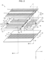
- the liquid ejecting head 26 which includes the first nozzle row L1 and the second nozzle row L2 is a laminated body in which head configuration materials are laminated.
- Fig. 2 is an exploded explanatory diagram illustrating the main head configuration materials of the liquid ejecting head 26.
- Fig. 3 is a sectional explanatory diagram illustrating the liquid ejecting head 26 taken along a III-III line in Fig. 2 .
- the thickness of each depicted configuration member does not indicate the actual configuration material thickness.
- some parts of a first flow path substrate 32 which is a configuration material are omitted.
- the liquid ejecting head 26 is provided with a configuration relating to the nozzles N of the first nozzle row L1 and a configuration relating to the nozzles N of the second nozzle row L2 symmetrically interposing the central surface O.
- a first portion P1 of the +X direction side and a second portion P2 of the -X direction side which interpose the central surface O have a common configuration.
- the nozzles N of the first nozzle row L1 belong to the first portion P1
- the nozzles N of the second nozzle row L2 belong to the second portion P2
- the central surface O is a boundary plane between the first portion P1 and the second portion P2.
- the liquid ejecting head 26 is provided with a flow path forming portion 30 which contributes to the flow path formation in the head, and a housing portion 48 which contributes to the supplying and discharging of the ink.
- the flow path forming portion 30 is configured by laminating the first flow path substrate 32 and a second flow path substrate 34. Both of the substrates of the first flow path substrate 32 and the second flow path substrate 34 are plate bodies which are long in the Y direction and the second flow path substrate 34 is fixed to a top surface Fa of the first flow path substrate 32 in the -Z direction using an adhesive.
- a vibrating portion 42, a plurality of piezoelectric elements 44, a protective member 46, and the housing portion 48 are installed on the top surface Fa side on the first flow path substrate 32.
- the vibrating portion 42 is installed to bridge from the first portion P1 to the second portion P2 and is a plate body having a thin shape which is long in the Y direction.
- the protective member 46 installed to bridge from the first portion P1 to the second portion P2 and is a plate body which is long in the Y direction.
- the protective member 46 forms a recessed space on the top surface side of the vibrating portion 42 and covers the vibrating portion 42.
- the housing portion 48 is a plate body which is long in the Y direction.
- the housing portion 48 pinches the protective member 46 against the second flow path substrate 34 of the flow path forming portion 30 on both sides of the central surface O.
- a nozzle plate 52 and vibration absorbing bodies 54 are disposed on a bottom surface Fb of the first flow path substrate 32 in the Z direction.
- the nozzle plate 52 and the vibration absorbing bodies 54 are all plate bodies which are long in the Y direction.
- the nozzle plate 52 is installed to bridge from the first portion P1 to the second portion P2.
- the vibration absorbing bodies 54 are installed individually on the first portion P1 and the second portion P2. Each of these elements adheres to a respective location on the top surface Fa or the bottom surface Fb of the first flow path substrate 32 using an adhesive.
- the nozzle plate 52 is provided with the nozzles N of the first portion P1 and the nozzles N of the second portion P2 in rows and is provided with two rows of circulation paths 72 between the first nozzle row L1 in which the nozzles N of the first portion P1 are lined up and the second nozzle row L2 in which the nozzles N of the second portion P2 are lined up.
- Each of the nozzles N is a circular through-hole which ejects the ink.
- the circulation paths 72 are sunk grooves which are formed in the surface of the nozzle plate 52.
- the circulation paths 72 of the +X direction row correspond to the nozzles N in the first nozzle row L1 and the circulation paths 72 of the -X direction row correspond to the nozzles N in the second nozzle row L2.
- the nozzle plate 52 is formed to include the nozzles N and the circulation paths 72 after applying a semiconductor manufacturing technique, for example, a processing technique such as dry etching or wet etching to a single crystal substrate of silicon (Si).
- a semiconductor manufacturing technique for example, a processing technique such as dry etching or wet etching to a single crystal substrate of silicon (Si).
- the vibration absorbing bodies 54 form the base surface of the liquid ejecting head 26 together with the nozzle plate 52 and close ink inflow chambers Ra and supply liquid chambers 60 as well as supply paths 61 through the adherence of the vibration absorbing bodies 54 to the bottom surface Fb of the first flow path substrate 32.
- the vibration absorbing bodies 54 is formed from flexible films which absorb pressure fluctuations in the ink inflow chambers Ra, for example, compliance substrates.
- the first flow path substrate 32 which is the adhesion target of the nozzle plate 52 and the vibration absorbing bodies 54, forms the ink inflow chambers Ra, the supply liquid chambers 60, the supply paths 61, and communicating paths 63 in association with the first portion P1 and the second portion P2 and forms a discharge liquid chamber 65 to be shared by the first portion P1 and the second portion P2.
- the ink inflow chambers Ra are penetrating openings which are long along the Y direction and each of the ink inflow chambers Ra is used in common for the ink supplying by the nozzles N in the first nozzle row L1 and the nozzles N in the second nozzle row L2, respectively.
- the supply paths 61 and the communicating paths 63 are through-holes which are formed for each of the nozzles N in the first nozzle row L1 and the second nozzle row L2.
- a longitudinal sunk groove which is formed in the bottom surface Fb of the first flow path substrate 32 adjacent to the ink inflow chamber Ra so as to go along the Y direction, is formed to be blocked together with the ink inflow chamber Ra and the supply path 61 by the adherence of the vibration absorbing bodies 54 to the bottom surface Fb of the first flow path substrate 32.
- the supply liquid chamber 60 contributes to the ink supplying from the ink inflow chamber Ra to the supply paths 61 of each of the nozzles N.
- a sunk groove which is formed in the bottom surface Fb of the first flow path substrate 32 to be long along the Y direction, is formed to be blocked together with the communicating paths 63 by the adhesion of the nozzle plate 52 to the bottom surface Fb of the first flow path substrate 32.
- the nozzle plate 52 is provided with each of the nozzles N of the first nozzle row L1 and the second nozzle row L2 and the circulation paths 72 corresponding to each of the nozzles N from each of the nozzle rows.
- Each of the nozzles N is installed at a position which overlaps the corresponding communicating path 63 in plan view from the Z direction.
- the circulation paths 72 are installed at positions which overlap partitioning wall portions 69 for each nozzle row which partition the communicating paths 63 and the discharge liquid chamber 65 in plan view from the Z direction.
- the circulation paths 72 form ink flow paths which span the partitioning wall portions 69 through the adhesion of the nozzle plate 52 to the bottom surface Fb of the first flow path substrate 32 and communicate the communicating paths 63 of each of the nozzles N with the discharge liquid chamber 65. Due to being communicated by the circulation paths 72, the discharge liquid chamber 65 receives an inflow of the ink from the communicating paths 63 of each of the nozzles N and contributes to the ink collection.
- the discharge liquid chamber 65 is a sunk groove which is longer than the nozzles N which are lined up in the first nozzle row L1 and the second nozzle row L2 and includes ink discharge ports 65a and 65b on both ends of the groove.
- the ink discharge ports 65a and 65b are through-holes which penetrate the base wall of the discharge liquid chamber 65 of the sunk groove, that is, the first flow path substrate 32 and are connected to circulation tubes in a circulation mechanism 75 (described later).
- the ink After flowing into the communicating paths 63, the ink passes through the circulation paths 72, enters the discharge liquid chamber 65, and is discharged from the liquid ejecting head 26 through the ink discharge ports 65a and 65b of the discharge liquid chamber 65. Since the ink which is discharged in this manner enters pressure chambers C (described later), a circulation flow path of the ink is formed between the circulation paths 72 which are downstream of the communicating paths 63 and the discharge liquid chamber 65.
- the second flow path substrate 34 which adheres to the top surface Fa of the first flow path substrate 32 forms the pressure chambers C in association with the first portion P1 and the second portion P2.
- the pressure chambers C are through-holes which go along the X direction and are formed for each of the nozzles N of the first nozzle row L1 and the second nozzle row L2 and communicate with the supply paths 61 and the communicating paths 63 of the first flow path substrate 32 on the bottom end side of the through-holes in the +Z direction.
- the pressure chambers C are closed at the through-hole top end side in the -Z direction by the vibrating portion 42 which is pinched by the protective member 46.
- the pressure chambers C which are closed in this manner functions as cavities for each of the nozzles N of the first nozzle row L1 and the second nozzle row L2.
- the first flow path substrate 32 and the second flow path substrate 34 are formed by subjecting a silicon single crystal substrate to a semiconductor manufacturing technique which is already described in the same manner as the nozzle plate 52.
- the vibrating portion 42 which is pinched between the second flow path substrate 34 and the protective member 46 is a plate-shaped member capable of elastic vibration and is provided with the piezoelectric elements 44 for each of the pressure chambers C which are closed in this manner. Accordingly, each of the piezoelectric elements 44 corresponds to the individual nozzles N of the first nozzle row L1 and the second nozzle row L2.
- the piezoelectric elements 44 correspond to a pressure generating unit in the invention.
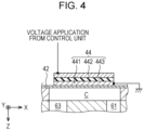
- Fig. 4 is an explanatory diagram schematically illustrating the schematic configuration of the piezoelectric element 44.
- the piezoelectric elements 44 are elements which receive drive signals from the control unit 200 and deform and are installed on the vibrating portion 42 corresponding to the nozzles N which are lined up.
- the piezoelectric elements 44 for each of the nozzles extend in the X direction to overlap the pressure chambers C.
- Each of the piezoelectric elements 44 is a laminated structural body in which a second electrode 442 is laminated on a first electrode 441, which is adhered to the vibrating portion 42, via a piezoelectric layer 443 which has insulating properties.
- the first electrode 441 is earthed and the second electrode 442 receives a series of liquid ejection requests from the control unit 200, in the present embodiment, the second electrode 442 receives the application of voltages individually corresponding to a series of printing requests which are necessary for printing an entire printing region.
- the piezoelectric element 44 flexes in the Z direction to cause a vibration in the Z direction and causes a pressure change in the ink which is already supplied to the pressure chamber C, in detail, in the ink which is passing through the pressure chamber C.
- the pressure change extends to the nozzle N through the communicating path 63.
- the first electrode 441 may be a common electrode to the piezoelectric elements 44 which are included in the first nozzle row L1, or alternatively, may be a common electrode to the piezoelectric elements 44 which are included in the second nozzle row L2.
- the piezoelectric element 44 receives a residual vibration which is caused by the ink of the pressure chamber C and vibrates during the period from when the piezoelectric element 44 receives the application of a voltage and vibrates until the piezoelectric element 44 receives the application of a voltage at a drive timing corresponding to the next printing request. During this period, since the piezoelectric element 44 does not receive a voltage application, the piezoelectric element 44 functions as an electrostatic actuator in which the first electrode 441 and the second electrode 442, which are good conductors, face each other separated by the piezoelectric layer 443 which has insulating properties.
- the piezoelectric element 44 causes an increasing or a decreasing change in the electrostatic capacity corresponding to the flexural vibration of the piezoelectric element 44 itself. It is possible to detect the vibration transition of the residual vibration which occurs in the ink of the pressure chamber C by inputting the electrostatic capacity change into a vibration generating circuit (described later). A detailed description of this point will be given later.
- the protective member 46 is a plate-shaped member for protecting the piezoelectric elements 44 which are present for each of the pressure chambers C and is pinched by the first flow path substrate 32 and the housing portion 48 in a state of pinching the vibrating portion 42 between the protective member 46 and the second flow path substrate 34.
- the protective member 46 may be formed by another material.
- the housing portion 48 is a member which covers the top surface side of the liquid ejecting head 26 and contributes to the protection of the overall head, to the storage of the ink which is supplied to the pressure chambers C which are present for each of the nozzles N, and to the ink refilling from the liquid container 14 (refer to Fig. 1 ).
- the housing portion 48 is provided with upstream side ink inflow chambers Rb which overlap the ink inflow chambers Ra of the first flow path substrate 32 in the Z direction and form ink storage chambers (reservoirs R) having common liquid chambers using the upstream side ink inflow chambers Rb and the ink inflow chambers Ra of the first flow path substrate 32.
- the ink supplying to the upstream side ink inflow chambers Rb is performed from ink inlets 49 of inflow chamber ceiling walls.
- the housing portion 48 is formed using injection molding of a suitable resin material.
- Fig. 5 is an explanatory diagram illustrating ink supply paths to the nozzles N and paths of ink circulation overlapping various flow path forming portions such as the supply paths 61 in the liquid ejecting head 26.
- the various path forming portions in the liquid ejecting head 26 are illustrated overlapping as viewed from the + +Z-axis direction.
- supply tubes 16 which go from the liquid container 14 to the ink inlets 49 and the tracks of collection tubes 78 which go from the discharge liquid chamber 65 to the circulation mechanism 75 (described later) are schematically illustrated including the installation positions of the liquid container 14 and the circulation mechanism 75.
- the III-III line illustrated in Fig. 5 indicates the cross-section plane of Fig. 3 corresponding to the III-III line illustrated in Fig. 2 .
- the reservoirs R which are configured by the ink inflow chambers Ra and the supply liquid chambers 60 (refer to Fig. 3 ) in the first flow path substrate 32 extend in the Y direction along each of the nozzle rows of the first nozzle row L1 and the second nozzle row L2.
- the reservoir R overlaps the supply paths 61 which are present for each of the nozzles which correspond to each of the nozzles N in the second nozzle row L2.
- the reservoir R overlaps the supply paths 61 corresponding to each of the nozzles N in the first nozzle row L1.
- the supply paths 61 of each of the nozzle rows overlap the pressure chambers C which are present for each of the nozzles and the pressure chambers C overlap the communicating paths 63 of each of the nozzle rows.
- the communicating paths 63 of the first flow path substrate 32 overlap the nozzles N of the nozzle plate 52 illustrated in Fig. 3 . Accordingly, the ink from the liquid container 14 is supplied to the reservoirs R by a pump 15 through the supply tubes 16 which are connected to the ink inlets 49.
- the ink which receives the pumping pressure of the pump 15 and is stored in the reservoirs R is supplied to the communicating paths 63 via the supply paths 61 and the pressure chambers C, receives the vibrations of the piezoelectric elements 44 which are driven and controlled by the control unit 200 in the pressure chambers C and is ejected from the nozzles N.
- the ink supplying from the liquid container 14 is continued even in a printing situation in which the ink ejection from the nozzles N is being performed, and even in a situation in which an ink ejection fault (described later), which does not accompany ink ejection from the nozzles N, is detected.
- the circulation mechanism 75 is provided with an ink storage tank 76 and a pressure adjustment unit 77 which adjusts the pressure inside the storage layer to a lower pressure than the pumping pressure of the pump 15.
- the circulation mechanism 75 receives circulated ink (described later), which is from the discharge liquid chamber 65, from the ink discharge port 65a and the ink discharge port 65b, and after storing the received circulated ink in the ink storage tank 76, circulates the ink into the reservoirs R via the ink inlets 49.
- the circulation of the circulated ink to the reservoir R through the ink inlets 49 is performed using the pressure adjustment of the pressure adjustment unit 77 (described later) which is performed on the pumping pressure of the pump 15.
- the discharge liquid chamber 65 extends in the Y direction between the first nozzle row L1 and the second nozzle row L2, is provided with the ink discharge port 65a further in the +Y direction than the bottommost nozzles N in the +Y direction in the nozzle rows, and is provided with the ink discharge port 65b further in the -Y direction than the topmost nozzles N in the -Y direction in the nozzle rows.
- the discharge liquid chamber 65 overlaps the circulation paths 72 corresponding to each of the nozzles N in the first nozzle row L1 in the first portion P1 and overlaps the circulation paths 72 corresponding to each of the nozzles N in the second nozzle row L2 in the second portion P2.
- the ink which exceeds the sum of the internal volume of the pressure chambers C and the communicating paths 63 is pushed out to the discharge liquid chamber 65 via the communicating paths 63 and the circulation paths 72, reaches the circulation mechanism 75 via the ink discharge ports 65a and 65b as the circulated ink, and is circulated to the reservoirs R by the circulation mechanism 75.
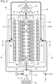
- Fig. 6 is a block diagram illustrating the main electrical configuration relating to ink ejection from the nozzles N exemplifying the correspondence with the piezoelectric element 44 in each of the pressure chambers C.
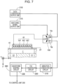
- Fig. 7 is a block diagram illustrating the main electrical configuration relating to the ink ejection from the nozzle N in association with the configuration of the piezoelectric element 44.
- the configuration elements are represented with an emphasized thickness.
- the control unit 200 receives an input of the print data from the print data transmitting device GM via an interface 201 (IF in Fig. 6 ) and outputs a display signal of text or the like to the display device GD via the interface 201. Additionally, in relation to the ink ejection, the control unit 200 is provided with various functional units which are interconnected to a bus.
- the functional units include an ink supplying unit 212, a data conversion output unit 210, a switching signal output unit 215, an ejection fault determination unit 220, and an ejection fault memory unit 230.
- the data conversion output unit 210 converts the print data (the series of printing requests) which is obtained through input from the print data transmitting device GM into voltage application data to the piezoelectric elements 44 for the ink ejection from each of the nozzles N of the first nozzle row L1 and the second nozzle row L2 and applies the voltages to the piezoelectric elements 44 for each of the nozzles N using the converted voltage application data.
- the switching signal output unit 215 generates signals which switch the piezoelectric elements 44 from a usage for the ink ejection to a usage of detection of the vibration transition of the residual vibration which is caused by the ink in the pressure chambers C after the ink ejection, and conversely, which perform the opposite switching and outputs the switching signal to a switcher 150 (described later).
- the ejection fault determination unit 220 determines whether or not there is a fault in the liquid ejection from the nozzles N using the vibration transitions of the residual vibration of the pressure chambers C which are obtained via the piezoelectric elements 44 and a residual vibration detection device 300 (described later).
- the ejection fault memory unit 230 stores the determination result of the ejection fault determination unit 220.
- the liquid ejecting apparatus 100 includes the residual vibration detection device 300 in relation to the detection of ink ejection faults.
- the residual vibration detection device 300 is provided with a vibration generating circuit 310, a voltage-frequency conversion circuit 320 (the F/V conversion circuit in the drawings) which achieves voltage-frequency conversion, and a waveform shaping circuit 330.
- the vibration generating circuit 310 is connected to the switcher 150 which handles each of the piezoelectric elements 44.
- the switcher 150 switches a connection destination of the second electrode 442 in the piezoelectric element 44 to one of an application position Vp and a vibration detection position Sp using the switching signal from the switching signal output unit 215.
- the vibration generating circuit 310 receives input of an increasing or decreasing change in the electrostatic capacity corresponding to the flexural vibration of the piezoelectric element 44 and vibrates in accordance with the increase or decrease in the electrostatic capacity which is input.
- the vibration occurs in a CR vibration generating circuit which uses a Schmitt trigger inverter having a hysteresis property as both a condenser (C) and a resistance (R).
- the voltage-frequency conversion circuit 320 is configured using several switching elements, capacitors, resistance elements, and fixed-current power sources and subjects a generated vibration waveform (a residual vibration waveform) which is output from the vibration generating circuit 310 to voltage-frequency conversion.
- the waveform shaping circuit 330 is configured using a capacitor for removing a direct current component and several resistance elements, direct current voltage sources, amplifiers, and comparators, converts the residual vibration waveform which undergoes the voltage-frequency conversion of the voltage-frequency conversion circuit 320 to a square wave and outputs the result to the ejection fault determination unit 220 of the control unit 200.
- the liquid ejecting apparatus 100 of the present embodiment anticipates a situation in which ink ejection faults from the nozzles N occur, a situation in which bubbles of a size capable of causing the ink ejection faults remain in the pressure chambers C, a situation in which foreign matter of a size capable of causing the ink ejection faults remain in the pressure chambers C, and a situation in which foreign matter such as paper fragments capable of causing the ink ejection faults block the opening regions of the nozzles N.
- the control unit 200 stores the transitions and periods of the residual vibration waveforms for each of the already ascertained situations in association with the origins of the ink ejection faults in a memory inside the unit or an external memory.
- the transitions and periods of the residual vibration waveforms are also stored for the ejection faults which are caused by an increase in the viscosity of the ink.
- Fig. 8 is an explanatory diagram schematically illustrating a state of recovery from ink ejection faults using the first recovery mechanism 110 which is provided outside of a printing region of the medium 12.
- the first recovery mechanism 110 is provided with a wiping member 114 which protrudes from a main body 112.
- the wiping member 114 has a brush structure which uses flexible rubber members or wires and performs the wiping for the recovery from the ejection faults.
- the first recovery mechanism 110 is ordinarily positioned closer to the +Z direction side than the liquid ejecting head 26.
- the control unit 200 raises the first recovery mechanism 110 and causes the wiping member 114 to protrude from the nozzle plate 52 in the liquid ejecting head 26.
- the wiping member 114 itself may be raised in the -Z direction, or alternatively, the entirety of the first recovery mechanism 110 may be raised.
- the control unit 200 causes the liquid ejecting head 26 to move in the -X direction.
- the wiping member 114 wipes the bottom surface of the nozzle plate 52 while bending as illustrated and the foreign matter such as paper fragments which adhere to the bottom surface of the nozzle plate 52 and block the openings of the nozzles N (refer to Fig. 3 ) are removed.
- the foreign matter removal may be performed using the first recovery mechanism 110 while causing the liquid ejecting head 26 to move reciprocally along the X direction.
- the first recovery mechanism 110 which recovers from the ejection faults of the ink from the nozzles N through wiping using the wiping member 114, corresponds to a recovery unit in the invention.
- Fig. 9 is an explanatory diagram schematically illustrating a state of recovery from ink ejection faults using the second recovery mechanism 120 which is provided outside of the printing region of the medium 12.
- the second recovery mechanism 120 stores an ink absorbing material 122 in an opening container 121 and is provided with an ink discharging tube 123 which is connected to the base wall of the opening container 121 for suctioning the inside of the container and discharging the ink which is absorbed by the ink absorbing material 122.
- the ink absorbing material 122 is formed from a non-woven fabric or a sponge cloth and absorbs and holds the ink which is ejected from the nozzles N.
- the second recovery mechanism 120 suctions (pumps) the inner portion of the opening container 121 using a suction pump (not illustrated) and discharges the ink which is absorbed and held by the ink absorbing material 122 through the ink discharging tube 123 which is connected to the base wall of the opening container 121.
- the second recovery mechanism 120 is ordinarily positioned closer to the +Z direction side than the liquid ejecting head 26.
- the control unit 200 causes the liquid ejecting head 26 to move to the outside of the printing region and stops the movement in a situation in which the ink ejection faults are to be recovered from by popping or flushing. Subsequently, the control unit 200 raises the opening container 121 of the second recovery mechanism 120 and covers, in an airtight manner, the entirety (refer to Fig. 5 ) of the nozzles N of the first nozzle row L1 and the second nozzle row L2 in the nozzle plate 52 with the opening of the opening container 121.
- the control unit 200 suctions the inside of the container of the opening container 121 while achieving the ink supplying to the pressure chambers C of the liquid ejecting head 26 during the popping process. Due to the popping, the bubbles and foreign matter which cause the faults in the ink ejection by remaining in the pressure chambers C and the communicating paths 63 downstream thereof are taken out by the ink which flows in the pressure chambers C. At this time, the piezoelectric elements 44 of the pressure chambers C may be driven.
- the control unit 200 drives the piezoelectric elements 44 of the pressure chambers C while achieving the ink supplying to the pressure chambers C of the liquid ejecting head 26 in a situation in which the opening container 121 is not suctioned such that a greater amount of the ink is ejected than the ink ejection amount during the printing. Due to the flushing, the bubbles and foreign matter which cause the faults in the ink ejection by remaining in the pressure chambers C and the communicating paths 63 downstream thereof are taken out by the ink which flows in the pressure chambers C.
- the second recovery mechanism 120 which recovers from the ejection faults of the ink from the nozzles N through popping or flushing, corresponds to a recovery unit in the invention.
- Fig. 10 is a flowchart illustrating a procedure of supplying control which achieves ink supplying to the liquid ejecting head 26.
- the supplying control is repeatedly executed by the ink supplying unit 212 of the control unit 200 while the printing is being performed by the liquid ejecting apparatus 100.
- the ink supplying unit 212 drives an ink supplying system from the liquid container 14 to the liquid ejecting head 26, specifically, the pump 15 of the supply tubes 16 at a predetermined pumping pressure and adjusts the pressure of the pressure adjustment unit 77 in the circulation mechanism 75 (step S100).
- the ink is supplied to each of the pressure chambers C through the reservoirs R and the supply liquid chambers 60 and the supply paths 61, and the ink which passes through the pressure chambers C is collected by the circulation mechanism 75 through the communicating paths 63, the circulation paths 72, and the discharge liquid chamber 65.
- the ink supplying unit 212 determines whether or not printing which is suitable for the series of printing requests which are obtained by receiving transmissions from the print data transmitting device GM is completed (step S110) and continues the ink supplying and collection to the pressure chambers C until the printing is completed. Meanwhile, when it is determined that the printing is completed, the ink supplying unit 212 also stops adjusting the pressure of the pressure adjustment unit 77 in addition to stopping the pump 15 (step S120) and ends the supplying control routine. Through the supplying control, over the period in which the series of printing requests which request the ink ejection from the nozzles N is present, the ink supplying to the plurality of pressure chambers C and the collection of the ink which passes through the pressure chambers C are continued.
- the supplying control and the ink supplying unit 212 which executes the supplying control configure a liquid supplying unit in the invention.
- the ink supplying unit 212 may also temporarily stop the ink supplying. For example, if the user cancels the printing, the ink supplying unit 212 temporarily stops the ink supplying and restores the ink supplying and collection in accordance with an instruction to clear the cancel or to restart the printing. As in the wiping for recovering from the ejection faults of the ink, if the ink supplying is unnecessary, the ink supplying may be temporarily stopped during the wiping and the ink supplying and the collection may be restored through the completion of the wiping. It is possible to also perform the wiping in the ink supplying.
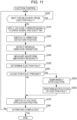
- Fig. 11 is a flowchart illustrating a procedure of ejection control which accompanies detection of the ejection faults of the ink.
- the ejection control is executed repeatedly by the control unit 200 accompanying the outputting of the print data by the data conversion output unit 210, the switching of the switcher 150 by the switching signal output unit 215, the ejection fault determination by the ejection fault determination unit 220, and the waveform shaping in the residual vibration detection device 300 in the period in which the printing is being performed by the liquid ejecting apparatus 100. Additionally, the ejection control is individually executed for each of the individual piezoelectric elements 44 using the piezoelectric elements 44 in each of the pressure chambers C of the first nozzle row L1 and the second nozzle row L2 as control targets.
- the switcher 150 is switched by the switching signal output unit 215 to the application position Vp at which the voltages are applied to the piezoelectric elements 44 in each of the pressure chambers C.
- the initial state of the switcher 150 is the application position Vp.
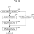
- the control unit 200 determines (step S200) whether the current point in time is a recovery waiting situation of ejection faults accompanying a temporary stopping of the ink ejection according to step S290 (described later).
- step S290 the control unit 200 determines (step S200) whether the current point in time is a recovery waiting situation of ejection faults accompanying a temporary stopping of the ink ejection according to step S290 (described later).
- the liquid ejecting apparatus 100 of the present embodiment upon temporarily stopping the ink ejection for the nozzle N, continues the ink supplying and collection to the specific nozzle, and upon continuing the ink supplying and collection for the other nozzles N, performs the ink ejection from the other nozzles through the driving of the piezoelectric elements 44.
- step S210 If there is no ejection fault in the control-target nozzle N, the control unit 200 determines that recovery waiting is not underway in the determination of recovery waiting of the ejection faults of step S200 and proceeds to the voltage application of the following step S210.
- the voltage application of step S210 is performed using the voltage application data, in which the print data is converted by the data conversion output unit 210 for the ink ejection from the control-target nozzle N, as a drive signal.
- step S210 if the control-target nozzle N is a nozzle N for which ink ejection is unnecessary, since the data conversion output unit 210 sets the voltage application data of the piezoelectric element 44 to null data for which driving is unnecessary, the ink ejection does not occur in the control-target nozzle N in step S210.
- the control-target nozzle N is a nozzle N for which the ink ejection is necessary
- the data conversion output unit 210 sets the voltage application data of the piezoelectric element 44 to a drive signal in which the driving is necessary, the voltage application is performed on the piezoelectric element 44 of the control-target nozzle N in step S210 and the ink ejection from the control-target nozzle N is performed.
- the control unit 200 causes the switching signal to be output from the switching signal output unit 215 to the switcher 150 and switches the switcher 150 from the application position Vp to the vibration detection position Sp (step S220). Due to the switching, since the increasing or decreasing change in the electrostatic capacity which corresponds to the flexural vibration of the piezoelectric element 44 is input to the vibration generating circuit 310 from the second electrode 442, the control unit 200 detects the vibration transition of the residual vibration which occurs in the ink of the pressure chamber C corresponding to the control-target nozzle N using the pressure change accompanying the driving of the piezoelectric element 44 in step S210 (step S230).
- a residual vibration waveform corresponding to the increasing or the decreasing change in the electrostatic capacity which is obtained by receiving an input from the second electrode 442 is obtained by the vibration generating circuit 310 as a vibration waveform and the vibration waveform is subjected to voltage-frequency conversion by the voltage-frequency conversion circuit 320. Subsequently, the conversion of the vibration waveform (the residual vibration waveform) which undergoes the voltage-frequency conversion of the voltage-frequency conversion circuit 320 to a square wave is performed.
- control unit 200 receives the square wave which is converted by the voltage-frequency conversion circuit 320 using the ejection fault determination unit 220 after the square wave undergoes waveform shaping in the waveform shaping circuit 330 and performs square wave frequency measurement which serves as waveform measurement using the ejection fault determination unit 220 (step S240).
- the ink ejection faults of the nozzles N occur due to nozzle blockage and the like caused by bubbles and foreign matter remaining in the pressure chambers C or by foreign matter such as paper fragments, and the liquid ejecting apparatus 100 of the present embodiment stores the transition, the period, the frequency, the attenuation ratio, and the like of the residual vibration waveforms in the pressure chambers C in these situations in memory.
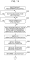
- the control unit 200 contrasts the period of the already stored residual vibration with the period of the residual vibration waveform which is measured at the present time in step S240 and determines whether or not an ejection fault of the ink is occurring in the control-target nozzle N from the contrasting results (step S260).
- An ejection fault determination in step S260 has the same meaning as determining that the vibration transition which is detected in step S230 is the ejection fault vibration transition corresponding to a fault in the liquid ejection from the control-target nozzle N. Accordingly, the ejection control including the determination of the ejection faults of steps S250 to S260 and the control unit 200 which executes the ejection control configure the ejection fault determination unit in the invention together with the residual vibration detection device 300.
- the control unit 200 determines that there is no ejection fault in step S260, and in the following step S270, the control unit 200 switches the switcher 150 from the vibration detection position Sp to the application position Vp. Accordingly, there are no impediments to the voltage application of the piezoelectric element 44 at the next ink ejection timing.
- the control unit 200 determines whether or not printing, which is suitable for the series of printing requests which are obtained by receiving a transmission from the print data transmitting device GM, is completed (step S280).
- the control unit 200 determines that the printing is completed, the control unit 200 ends the ejection control routine, and if the printing is incomplete, the control unit 200 transitions to step S200 and repeats the processes that are already described. Accordingly, in a situation in which the control unit 200 determines that the control-target nozzle N has an ejection fault in step S260, the detection of an ejection fault is performed for every ink ejection timing according to a drive signal which defines whether or not the ink ejection is present in the control-target nozzle N.
- the detection of the vibration transition of the residual vibration which occurs in the ink in the pressure chamber C of the control-target nozzle N caused by a pressure change which accompanies the driving of the piezoelectric element 44 for the ink ejection is executed using the duration of the consecutive ink ejection timings according to the drive signals as a detection period.
- step S260 when the control unit 200 determines that there is a fault in the ink ejection in the control-target nozzle N caused by remaining bubbles or the like in the pressure chamber C in step S260, the control unit 200 temporarily stops the ink ejection from the control-target nozzle N (step S290).
- the pressure chamber C of the control-target nozzle N which is determined to have an ink ejection fault is an ejection fault pressure chamber in the invention.
- step S260 the control-target nozzle N which is determined to have an ink ejection fault is a nozzle N corresponding to the ejection fault pressure chamber in the invention.
- step S290 of temporarily stopping the ink ejection from the control-target nozzle N has the same meaning as stopping the driving of the piezoelectric element 44 of the control-target nozzle N spanning at least a fixed stopping period regardless of the series of printing requests.
- a situation in which the driving of the piezoelectric element 44 of the control-target nozzle N is stopped by the process of step S290 is the driving stopping time of the piezoelectric element 44.
- the temporary stopping of the ink ejection from the control-target nozzle N is performed together with the driving stopping of the piezoelectric element 44 for the pressure chamber C of the control-target nozzle N.
- the control unit 200 temporarily stops the ink ejection in step S290 spanning a fixed stopping period of approximately 1 to 30 seconds, for example.
- the fixed stopping period will be referred to as a temporary stopping period.
- the control unit 200 determines that there is an ejection fault in step S260, the control unit 200 stores the origin, specifically, one of the presence of bubbles in the pressure chamber C, the presence of foreign matter in the pressure chamber C, and the blockage of the nozzle by foreign matter such as paper fragments in the ejection fault memory unit 230 together with nozzle data with which it is possible to specify the control-target nozzle N which causes the ejection fault.
- the stored result may be used when performing the recovery process on the control-target nozzle N which causes the ejection fault.
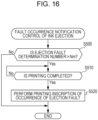
- the control unit 200 performs notification of the fact that an ejection fault occurs in the control-target nozzle N (step S292).
- the control unit 200 displays text such as "ink ejection fault occurred", an image which causes recognition of the ejection fault, or the like on the display device GD, performs blinking control of a warning lamp (not illustrated) which is included in the liquid ejecting apparatus 100, or the like to perform notification of the fact that an ejection fault occurs in the control-target nozzle N.
- control unit 200 performs the notification of the ejection fault
- the control unit 200 transitions to step S270 and switches the switcher 150 from the vibration detection position Sp to the application position Vp. Accordingly, there are no impediments to the voltage application of the piezoelectric element 44 at the ink ejection timing after the recovery waiting of the ejection fault.
- step S280 After temporarily stopping the ink ejection from the control-target nozzle N due to an ink ejection fault, the control unit 200 performs print completion determination in step S280 after transitioning to step S270 and subsequently transitions to step S200.
- step S200 which is transitioned to in this manner, a negative determination is performed continually spanning the temporary stopping period from the temporary stopping of the ejection of the control-target nozzle N in step S290 in the previous ejection control. Accordingly, although the driving of the piezoelectric element 44 is not performed in the temporary stopping period for the control-target nozzle N which is determined to have an ejection fault, according to the supplying control illustrated in Fig.
- the ink supplying and collection is performed intermittently in the pressure chamber C corresponding to the control-target nozzle N. Accordingly, the bubbles and foreign matter caused by the ink which passes through the pressure chamber C corresponding to the control-target nozzle N in the temporary stopping period are expected to be taken out and a recovery from the ejection fault is also expected.
- step S200 since it is determined that the recovery waiting of the ejection fault is completed, after the elapsing of the temporary stopping period, the processes of step S210 onward are repeated and the ink ejection from the control-target nozzle N is restarted.
- the liquid ejecting apparatus 100 of the first embodiment which is described hereinabove continues the supplying of the ink to the pressure chambers C of each of the plurality of nozzles N and the collection of the ink which passes through each of the pressure chambers C using the supplying control illustrated in Fig. 10 .
- the liquid ejecting apparatus 100 of the first embodiment ejects the ink from the nozzles N using pressure changes in the ink in the pressure chambers C caused by the piezoelectric element 44 in each of the pressure chambers C in a situation in which the supplying and collection of the ink to the pressure chamber C of each of the plurality of nozzles N are continued.
- the liquid ejecting apparatus 100 of the first embodiment stops the ink ejection from the control-target nozzle N in which the ejection fault occurs spanning a temporary stopping period (step S290), and after the temporary stopping period elapses, restarts the ink ejection from the control-target nozzle N which is determined to have the ejection fault.
- the ink ejection stopping target is the control-target nozzle N which is determined to have an ejection fault, and in the other nozzles N, the ink ejection is continued even in the temporary stopping period due to the driving of the piezoelectric elements 44 corresponding to the series of printing requests.
- the liquid ejecting apparatus 100 of the first embodiment in addition to being capable of handling the bubbles and foreign matter even if inter-reservoir circulation in the Y direction or the like is not performed, it is possible to perform the removal of the bubbles and foreign matter and the erasure of the bubbles from the control-target nozzle even during the ink ejection of the nozzles other than the control-target nozzle.
- the liquid ejecting apparatus 100 of the first embodiment is provided with the first recovery mechanism 110 which performs the wiping and the second recovery mechanism 120 which is capable of popping or flushing to achieve a recovery from ink ejection faults. Accordingly, in the course of repeating the ejection control illustrated in Fig. 11 , in a case in which ejection faults occur in a plurality of the nozzles N or in which an ejection fault occurs repeatedly in a certain specific nozzle N, it is possible to reliably recover from the ejection faults through wiping by the first recovery mechanism 110 and the popping and the flushing which use the second recovery mechanism 120.
- the control-target nozzle N which causes the ejection fault is stored in association with the fault origin as described earlier, during the flushing which uses the second recovery mechanism 120, it is possible to achieve fault recovery by ejecting (flushing) a greater amount of the ink from the control-target nozzle N than the ink ejection amount during the printing for only the control-target nozzle N which causes the ejection fault.
- the second recovery mechanism 120 is configured to enable the popping of individual nozzles N, even if the popping uses the second recovery mechanism 120, it is possible to perform suction (the popping) for only the control-target nozzle N which causes the ejection fault to achieve the fault recovery.
- the liquid ejecting apparatus 100 of the first embodiment temporarily stops the ink ejection from the control-target nozzle N, the liquid ejecting apparatus 100 notifies the user of the fact that an ejection fault occurs in the control-target nozzle N using text display on the display device GD or the like. Therefore, according to the liquid ejecting apparatus 100 of the first embodiment, it is possible to cause the user to recognize the fact that there is a possibility of the occurrence of a reduction in the quality of the printed image or the like which may be obtained on the medium 12 using the ink ejection from the liquid ejecting head 26.
- the liquid ejecting apparatus 100 of the first embodiment drives the piezoelectric elements 44 of the pressure chambers C while causing the liquid ejecting head 26 to scan in the main scanning direction with respect to the medium 12 and causes the acceleration which accompanies the scanning of the liquid ejecting head 26 in the main scanning direction to influence the pressure chamber C corresponding to the control-target nozzle N which causes an ejection fault.
- the liquid ejecting apparatus 100 of the first embodiment since it is possible to cause the bubbles and the foreign matter which are mixed into the ink of the pressure chamber C corresponding to the control-target nozzle N which causes the ejection fault to move to the discharge liquid chamber 65 side using the acceleration during the scanning, it is possible to expect an early recovery of the control-target nozzle N which is an ejection fault nozzle.
- Fig. 12 is a flowchart illustrating a procedure of ejection control in a liquid ejecting apparatus of a second embodiment.
- the ejection control of the liquid ejecting apparatus of the second embodiment is individually executed for each of the individual piezoelectric elements 44 using the piezoelectric elements 44 in each of the pressure chambers C of the first nozzle row L1 and the second nozzle row L2 as control targets in a printing situation.
- control unit 200 performs determination of whether the situation is a recovery waiting situation from an ejection fault which accompanies a temporary stopping of the ink ejection (step S200) and waits for the recovery from the ejection fault.
- the control unit 200 determines whether or not the nozzle N which is adjacent to the control-target nozzle N at the current time, for example, if the control-target nozzle N is a nozzle N belonging to the first nozzle row L1, the nozzle N which belongs to the second nozzle row L2 and is the nozzle N which is adjacent to the control-target nozzle N in the main scanning direction, is determined to have an ejection fault in the ejection control until the current time (step S202).
- the pressure chamber C of the adjacent nozzle N corresponds to an adjacent pressure chamber in the invention.
- control unit 200 determines that an ejection fault does not occur in the adjacent nozzle N, the control unit 200 transitions to step S210 which is already described and applies a voltage corresponding to the drive signal which matches the control-target nozzle N to the piezoelectric element 44 of the control-target nozzle N. Subsequently, the control unit 200 executes the processes of step S220 onward which are already described.
- step S202 when the control unit 200 determines that there is an ejection fault in the adjacent nozzle N, the control unit 200 converts the drive signal which is originally associated with the control-target nozzle N into a supplementary corresponding signal which supplements the drive signal such that the vibration of the piezoelectric element 44 is increased in size (step S204). Accordingly, a voltage, which is supplemented such that a greater amount of the ink ejection occurs than the ejection droplet amount of the ink originally to be ejected using the supplementary corresponding signal, is applied to the piezoelectric element 44 of the control-target nozzle N.
- step S204 the control unit 200 executes the processes of step S220 onward which are already described.
- step S250 since the residual vibration, the amplitude, and the frequency are different due to the pressure change being large in the piezoelectric element 44 which brings about the increased-amount ejection in step S204, this point is taken into consideration.
- a configuration may be adopted in which the residual vibration transition of a case in which the supplementary ejection is performed in advance is anticipated and stored as described earlier, the residual vibration transition after undergoing step S204 is contrasted with the stored result, and the presence or absence of an ejection fault is determined.
- the ejection control of the second embodiment is repeated until the printing completion in the same manner as in the first embodiment. Accordingly, the supplementary ejection of the control-target nozzle N is continued during the period until the ejection fault in the adjacent nozzle N is recovered from and the driving of the piezoelectric element 44 of the adjacent nozzle N is restarted to receive the original voltage application.
- liquid ejecting apparatus of the second embodiment In the liquid ejecting apparatus of the second embodiment described above, even if an ink ejection fault occurs in a nozzle N belonging to one row of the first nozzle row L1 and the second nozzle row L2, an amount of ink corresponding to that which could not be ejected from the nozzle N having the ejection fault is supplemented and ejected from the nozzle N which is adjacent to the nozzle N having the ejection fault in the main scanning direction. Therefore, according to the liquid ejecting apparatus of the second embodiment, it is possible to suppress a quality reduction in the printed item such as a printed image which is printed on the medium 12.
- Fig. 13 is a flowchart illustrating a procedure of a prior half of redetermination control of an ejection fault in a liquid ejecting apparatus of a third embodiment.
- Fig. 14 is a flowchart illustrating a procedure of a latter half of the redetermination control of an ejection fault in the liquid ejecting apparatus of the third embodiment.
- the redetermination control is executed by the control unit 200 together with the switching of the switcher 150 by the switching signal output unit 215, the ejection fault determination by the ejection fault determination unit 220, and the waveform shaping by the residual vibration detection device 300 in the period in which an ejection fault occurs in the control-target nozzle N in the ejection control and the ink ejection from the nozzle is temporarily stopped.
- the redetermination control is executed using the piezoelectric element 44 in the pressure chamber C of the control-target nozzle N in which it is determined that an ejection fault occurs in the ejection control as a control target. Accordingly, in the following explanation, the control-target nozzle in the redetermination control will be referred to as the redetermination-target nozzle N.
- the switcher 150 is switched by the switching signal output unit 215 to the application position at which the voltages are applied to the piezoelectric elements 44 in the pressure chambers C.
- the control unit 200 determines whether the situation is a recovery waiting situation of ejection faults accompanying a temporary stopping of the ink ejection according to step S290 in the executed ejection control (step S300) and no processes are performed if the situation is not the recovery waiting situation. If there is no ejection fault in the executed ejection control, the liquid ejecting apparatus 100 is not in the state of recovery waiting from an ejection fault. Accordingly, the redetermination control is first executed when it is determined that there is an ejection fault in the executed ejection control and the ejection is temporarily stopped.
- step S300 when the control unit 200 determines that the situation is the recovery waiting situation from an ejection fault, the control unit 200 determines whether or not a redetermination span is elapsed (step S305) and waits until the redetermination span is elapsed.
- the redetermination span defines the interval when repeatedly executing the various types of redetermination processes of the redetermination control in a situation in which it is determined that there is an ejection fault in the executed ejection control.
- the redetermination span is set to 1 to 40 seconds.
- the redetermination span is longer than a fault determination span in the ejection fault determination in the ejection control, that is, longer than the detection span (the detection period) of the ejection fault between consecutive ink ejection timings according to the drive signals.
- the control unit 200 applies the non-ejecting voltage in which the ink ejection does not occur to the piezoelectric element 44 of the pressure chamber C of the redetermination-target nozzle N (step S310). Due to the application of the non-ejecting voltage, in the pressure chamber C of the redetermination-target nozzle N, a pressure change, which does not cause the ink ejection from the redetermination-target nozzle N, occurs.
- control unit 200 causes a switching signal to be output from the switching signal output unit 215 to the switcher 150 and switches the switcher 150 from the application position Vp to the vibration detection position Sp (step S315).
- the control unit 200 detects the vibration transition of the residual vibration which occurs in the ink of the pressure chamber C corresponding to the redetermination-target nozzle N using the pressure change accompanying the driving of the piezoelectric element 44 in step S310 (step S320).
- a residual vibration waveform corresponding to the increasing or the decreasing change in the electrostatic capacity which is obtained by receiving an input from the second electrode 442 is obtained by the vibration generating circuit 310 as a vibration waveform and the vibration waveform is subjected to voltage-frequency conversion by the voltage-frequency conversion circuit 320. Subsequently, the conversion of the vibration waveform (the residual vibration waveform) which undergoes the voltage-frequency conversion of the voltage-frequency conversion circuit 320 to a square wave is performed.
- the control unit 200 receives the square wave which is converted by the voltage-frequency conversion circuit 320 using the ejection fault determination unit 220 after the square wave undergoes waveform shaping in the waveform shaping circuit 330 and performs square wave frequency measurement which serves as waveform measurement using the ejection fault determination unit 220 (step S325).
- the voltage application in step S310 is an application at a non-ejecting voltage which does not cause the ink ejection, the voltage application brings about a residual vibration which is different in amplitude and period from the voltage application when the ink ejection is caused.
- the transition and the period of the residual vibration waveform which occurs in the ink of the pressure chamber C in the non-ejecting voltage application which does not cause the ink ejection are stored in memory in advance in association with the ejection fault origin.
- step S330 the control unit 200 contrasts the period of the already stored residual vibration with the period of the residual vibration waveform which is based on the non-ejecting voltage application which is measured in step S325 and determines (redetermined) whether or not an ejection fault of the ink is occurring in the redetermination-target nozzle N from the contrasting results (step S335).
- the redetermination control including step S335 is executed after determining that an ejection fault occurs using the previous ejection control as described earlier. Accordingly, the ejection fault determination in step S335 determines whether the fault in the ink ejection in the pressure chamber C of the redetermination-target nozzle N continues to be present or the ejection fault is recovered from.
- control unit 200 determines that there is no ejection fault in the redetermination-target nozzle N after undergoing the detection of the residual vibration transition based on the non-ejecting voltage application (step S320), that is, that the ejection fault is recovered from using step S335, the control unit 200 cancels the temporary stopping of the ejection which is performed in the ejection control (step S340). Accordingly, the ink ejection is restarted from the control-target nozzle N at the timing of the ink ejection at the current time onward.
- the redetermination control which performs the temporary stopping cancellation of the ejection according to step S340 is performed during the period in which the ink ejection from the control-target nozzle N which is determined to have generated an ejection fault is temporarily stopped. Accordingly, due to the cancellation of the temporary stopping of the ejection according to step S340, the driving of the piezoelectric element 44 of the pressure chamber C for the control-target nozzle N is restarted regardless of the passage of the temporary stopping period which is defined in advance.
- the control unit 200 Continuing from the cancellation of the temporary stopping of the ejection, the control unit 200 resets an ejection fault number counter Fc which represents the number of times the control unit 200 redetermines that an ejection fault is present in the present redetermination control (step S345). Subsequently, in the same manner as the ejection control, the control unit 200 switches the switcher 150 from the vibration detection position Sp to the application position Vp (step S350) and temporarily ends the redetermination control. Accordingly, there are no impediments to the voltage application of the piezoelectric element 44 at the ink ejection timing from when the temporary stopping of the ejection is canceled in step S340 onward.
- the control unit 200 determines that the ejection fault continues in the pressure chamber C of the redetermination-target nozzle N in step S335, the control unit 200 increments the ejection fault number counter Fc by a value of 1 (step S355), transitions to the switching of step S350, and subsequently temporarily ends the redetermination control.
- the ejection fault number counter Fc is incremented every time the continuation determination of the ejection fault is performed in step S335 until either the resetting in step S345 after undergoing the recovery determination of the ejection fault in step S335 or the resetting in the recovery control (described later) is performed.
- control unit 200 determines that the ejection fault is continued in step S335, in the same manner as in the case of the ejection control, the control unit 200 the origin of the ejection fault in the ejection fault memory unit 230 together with nozzle data capable of specifying the redetermination-target nozzle N which is determined to have a continuing ejection fault.
- the stored result becomes usable when performing the recovery process on the redetermination-target nozzle N for which it is redetermined that the ejection fault is continuing.
- Fig. 15 is a flowchart illustrating a procedure of recovery control from the ejection faults in the liquid ejecting apparatus of the third embodiment.
- the recovery control is executed while keeping the execution timing of the redetermination control while the redetermination control is being performed.
- the control unit 200 determines whether or not the number of times it is determined that an ejection fault is consecutively present in the redetermination control, that is, whether or not the ejection fault determination number reaches a predetermined fault determination number Nm (step S400). The determination is performed by comparing the ejection fault number counter Fc which represents the ejection fault determination number with the fault determination number Nm.
- the fault determination number Nm is set to be smaller the greater the passage amount of the ink which passes through the pressure chamber C, or alternatively, the higher the ink temperature (the liquid temperature).
- the control unit 200 senses the pump pumping pressure, and sets the fault determination number Nm to a small value if the ink passage amount is greater than a defined value.
- the control unit 200 sets the fault determination number Nm to a low value with the premise that the ink temperature is also higher than the defined temperature.
- control unit 200 determines that the ejection fault determination number does not reach the predetermined fault determination number Nm in step S400, the control unit 200 ends the present recovery control without performing the processes thereafter. Meanwhile, if the control unit 200 determines that the ejection fault determination number reaches the predetermined fault determination number Nm in step S400, the control unit 200 temporarily stops the ink ejection from all of the nozzles N of the first nozzle row L1 and the second nozzle row L2 (step S410). The ink ejection is not performed until the ejection is restored after undergoing the recovery process from the ejection fault (described later) according to the temporary stopping of the ejection. In other words, the data conversion output unit 210 stops the outputting of the drive signals corresponding to the print data to each of the nozzles N at the time at which the temporary stopping of the ejection is performed in step S410.
- the control unit 200 upon storing the stopping position of the liquid ejecting head 26 in the main scanning direction at the current time, the control unit 200 causes the liquid ejecting head 26 to move to a recovery position (step S420).
- the control unit 200 reads the stored result, specifically, one of the ejection fault caused by remaining bubbles in the pressure chamber C, the ejection fault caused by foreign matter in the pressure chamber C, or the ejection fault caused by blockage by foreign matter of the nozzle N.
- the control unit 200 causes the liquid ejecting head 26 to move to the recovery position corresponding to the origin of the ejection fault.
- the control unit 200 causes the liquid ejecting head 26 to move to the recovery position of the second recovery mechanism 120 as illustrated in Fig. 9 . If the ejection fault is the ejection fault caused by the blockage of the nozzle N by the foreign matter, the control unit 200 causes the liquid ejecting head 26 to move to the recovery position of the first recovery mechanism 110 as illustrated in Fig. 8 .
- the control unit 200 performs the recovery measure corresponding to the ejection fault (step S430). Specifically, if the ejection fault is the ejection fault caused by bubbles remaining in the pressure chamber C or the ejection fault caused by foreign matter in the pressure chamber C, popping or flushing is executed in order to achieve the carrying out of the remaining bubbles or foreign matter using the ink which flows from the pressure chamber C to the discharge liquid chamber 65.
- the popping upon pressing the second recovery mechanism 120 against the nozzle plate 52 of the liquid ejecting head 26 in an airtight manner, the inside of the container of the opening container 121 is suctioned while achieving the ink supplying to the pressure chambers C of the liquid ejecting head 26. Due to the popping, the bubbles and foreign matter which cause the faults in the ink ejection by remaining in the pressure chambers C and the communicating paths 63 downstream thereof are taken out by the ink which flows in the pressure chambers C.
- the piezoelectric elements 44 of the pressure chambers C are driven while achieving the ink supplying to the pressure chambers C of the liquid ejecting head 26 in a situation in which the opening container 121 is not suctioned such that a greater amount of the ink is ejected than the ink ejection amount during the printing. Due to the flushing, the bubbles and foreign matter which cause the faults in the ink ejection by remaining in the pressure chambers C and the communicating paths 63 downstream thereof are taken out by the ink which flows in the pressure chambers C.
- the flushing may be performed only on the nozzles N for which ejection faults occur.
- the first recovery mechanism 110 is raised and the wiping member 114 is caused to protrude from the nozzle plate 52 in the liquid ejecting head 26.
- the liquid ejecting head 26 is caused to move in the -X direction, is caused to move reciprocally along the X direction, or the like to execute the wiping using the wiping member 114 and the foreign matter such as the paper fragments which adhere to the bottom surface of the nozzle plate 52 and block openings of the nozzles N are removed.
- the control unit 200 causes the liquid ejecting head 26 to be restored to the ejecting position during the temporary stopping of the ejection from the recovery position (step S440) and subsequently cancels the temporary stopping of the ejection and restores the ejection (step S450).
- the data conversion output unit 210 outputs the drive signals of the time at which the stopping is performed corresponding to the temporary stopping of the ejecting in step S410 onward to each of the nozzles N. Accordingly, the printing which is stopped together with the recovery from the ejection fault is restarted.
- control unit 200 resets the ejection fault number counter Fc (step S460) and ends the recovery control.
- the liquid ejecting apparatus of the third embodiment applies the non-ejecting voltage of a low voltage which does not cause the ink ejection to the piezoelectric element 44 (step S310) and repeats a redetermination of the ejection fault from the vibration transition of the residual vibration which occurs in the ink of the pressure chamber C based on the application of the non-ejecting voltage (steps S320 to S335).
- the liquid ejecting apparatus of the third embodiment determines that there is no fault in the ink ejection from the control-target nozzle N in the redetermination (step S335), the liquid ejecting apparatus restarts the driving of the piezoelectric element 44 of the pressure chamber C for the control-target nozzle N regardless of the passage of the temporary stopping period of the ink ejection (step S340). Accordingly, according to the liquid ejecting apparatus of the third embodiment, it is possible to restart the ink ejection from the control-target nozzle N in which an ejection fault occurs at an early stage.
- the redetermination span is rendered longer than the detection span (the detection period) during consecutive ink ejection timings which are the fault determination span in the ejection fault determination in the ejection control when repeatedly performing the redetermination after undergoing the application of the non-ejecting voltage for the control-target nozzle N in which it is determined that the ejection fault of the ink occurs. Accordingly, according to the liquid ejecting apparatus of the third embodiment, it is possible to achieve the following effects.
- the application may influence the flow of the ink which passes through the pressure chamber C for the redetermination-target nozzle N.
- the redetermination span which is the redetermination period longer than the detection span (the detection period) before performing the redetermination, it is possible to reduce the influence of the pressure change during the redetermination on the flow of the ink which passes through the pressure chamber C for the redetermination-target nozzle N.
- the liquid ejecting apparatus of the third embodiment by ensuring that the taking out of bubbles and foreign matter using the ink which passes through the pressure chamber C for the redetermination-target nozzle N is not impeded, it is possible to recover from the ejection fault in the redetermination-target nozzle N which is the ejection fault nozzle at an early stage.
- the liquid ejecting apparatus of the third embodiment is provided with the first recovery mechanism 110 and the second recovery mechanism 120 which achieve the recovery from ejection faults and the liquid ejecting apparatus repeats the redetermination of the ejection fault for the redetermination-target nozzle N in which it is determined that an ejection fault is present in the ejection control.
- step S400 When it is consecutively determined that there is a fault in the ink ejection in the redetermination-target nozzle N over the predetermined fault determination number Nm in the redetermination (step S400), upon temporarily stopping the ink ejection from the redetermination-target nozzle N (step S410), the first recovery mechanism 110 or the second recovery mechanism 120 is used to recover from the ejection fault of the ink from the redetermination-target nozzle N (step S430). Accordingly, according to the liquid ejecting apparatus of the third embodiment, it is possible to reliably restart the ink ejection from the redetermination-target nozzle N in which an ejection fault occurs.
- the fault determination number Nm which defines the timing at which to achieve the recovery from the ejection fault using the first recovery mechanism 110 or the second recovery mechanism 120 is set to be smaller the greater the passage amount of the ink which passes through the pressure chamber C, or alternatively, the higher the ink temperature. Accordingly, according to the liquid ejecting apparatus of the third embodiment, it is possible to achieve the following effects. The greater the passage amount of the ink which passes through the pressure chamber C, the higher the chance that the bubbles or foreign matter which enters the pressure chamber C will be taken away by the ink which passes through the pressure chamber C.
- the liquid ejecting apparatus of the third embodiment even if the fault determination number Nm is reduced and the number of times the fault determination is performed is reduced, it is possible to secure the reliability of the taking out of the bubbles or foreign matter by the ink which passes through the pressure chamber C and the recovery from the ejection fault due to the taking away also progresses.
- Fig. 16 is a flowchart illustrating a procedure of fault occurrence notification control of the ink ejection in a liquid ejecting apparatus of a fourth embodiment.
- the control unit 200 determines whether or not the ejection fault determination number reaches the predetermined fault determination number Nm in the same manner as the recovery control (step S500). If the control unit 200 determines that the ejection fault determination number does not reach the predetermined fault determination number Nm in step S500, the control unit 200 ends the present recovery control without performing the processes thereafter.
- control unit 200 determines whether or not all of the printing corresponding to the print data from the print data transmitting device GM is completed (step S510) and waits until the printing is completed.
- Fig. 17 is an explanatory diagram illustrating an example of notification of ink ejection.
- the liquid ejecting apparatus 100 prints, for example, text such as "there is a possibility that ink ejection faults occurred in the course of printing” or “ejection faults present", or a symbol which is associated in advance with the meaning that there is a possibility that ink ejection faults occurred in the course of printing on an inscription region Pr on a discharging rear end side of the medium 12 which is outside of the printing region of the printing image or the like based on the print data from the print data transmitting device GM. Since the printing is not included in the print data from the print data transmitting device GM, the drive signals necessary for the printing of the text or the symbol is output from the data conversion output unit 210 in step S520.
- the fault notification of this fact is performed using marking which undergoes the ink ejection from the nozzles N onto the medium 12 which is the ejection target of the ink as illustrated in Fig. 17 .
- the present embodiment even if it is determined that an ejection fault of the ink occurs, since the supplying and collection of the ink to the pressure chamber C is continued, it is anticipated that the ejection fault is recovered from. However, notifying the user of the fact that the ejection fault occurs is beneficial.
- the liquid ejecting apparatus of the fourth embodiment it is possible to cause the user of the liquid ejecting apparatus to easily recognize the fact that there is a possibility of the occurrence of a reduction in the quality of the ejection product such as the printed image which may be obtained on the medium 12 which is the ejection target of the ink ejection from the nozzles N.
- Fig. 18 is a flowchart illustrating a procedure of fault occurrence notification control of the ink ejection in a liquid ejecting apparatus of a fifth embodiment.
- the control unit 200 determines whether or not all of the printing corresponding to the print data from the print data transmitting device GM is completed (step S600). If the control unit 200 determines that the printing is not completed in step S600, the control unit 200 ends the present recovery control without performing the processes thereafter.
- step S610 the control unit 200 determines whether or not the ejection fault determination number reaches the predetermined fault determination number Nm.
- the control unit 200 determines whether or not the ejection fault determination number reaches the predetermined fault determination number Nm (step S610).
- the control unit 200 discharges the medium 12 for which the printing is completed to the outside of the ejection region of the ink in the ordinary discharge path (step S620) and ends the fault notification control.
- Fig. 19 is an explanatory diagram illustrating a state of discharging the medium 12 for which printing is completed as ordinary in contrast with a state of discharging the medium 12 in an unordinary discharge path.
- the liquid ejecting apparatus 100 subjects a medium 12a for which the printing is completed without the ejection fault determination number reaching the predetermined fault determination number Nm to the control of the transport mechanism 22 using the control unit 200 and outputs the medium 12a straight along the +Y direction as illustrated by a white-filled arrow A. Meanwhile, the liquid ejecting apparatus 100 subjects a medium 12b for which the ejection fault determination number reaches the predetermined fault determination number Nm and the printing is completed to the control of the transport mechanism 22 using the control unit 200 and outputs the medium 12b obliquely along +X direction and the +Y direction as illustrated by a white-filled arrow B.
- the medium discharging becomes possible by providing a discharge medium receiving table closer to the bottom side of the head in the +Z direction than the liquid ejecting head 26.
- the control unit 200 causes the discharge medium receiving table to move in the -X direction from an origin position at which the discharge medium receiving table receives the discharging of the medium 12a before the discharging of the medium 12b. Subsequently, after causing the medium 12b to be discharged onto the discharge medium receiving table which is already moved in the -X direction, the control unit 200 restores the discharge medium receiving table to the origin position. Accordingly, it is possible to discharge the medium 12b to a different discharge location from that of the medium 12a.
- the medium 12b may be discharged to a different discharge location from the medium 12a such that the medium leading end of the medium 12b is positioned further in the +Y direction than that of the medium 12a. Accordingly, it is sufficient to change the rotational speed of the medium feed roller and set the length of the medium discharge length in the transport mechanism 22, which is convenient.
- the liquid ejecting apparatus of the fifth embodiment ends the ink ejection from the nozzle N corresponding to the print data which is the series of liquid ejection requests and completed the printing
- the liquid ejecting apparatus discharges the medium 12a for which the printing is completed with the ejection fault determination number not reaching the predetermined fault determination number Nm and the medium 12b for which the printing is completed with the ejection fault determination number reaching the predetermined fault determination number Nm to different discharge locations on the outside of the ejection region of the ink.
- the medium 12a for which the printing is completed with the ejection fault determination number not reaching the predetermined fault determination number Nm includes the medium 12 which receives the ink ejection from the nozzles N which are determined not to have ink ejection faults in the ejection control.
- the fault determination span in the ejection fault determination in the ejection control is set to the detection span (the detection period) during the consecutive ink ejection timings according to the drive signals
- the fault determination span is not limited to the detection span (the detection period) during the ink ejection timings as long as the fault determination span is shorter than the redetermination span in which the ejection fault is redetermined using the residual vibration transition after undergoing the application of the non-ejecting voltage in the redetermination control of the ejection fault.
- the fault determination span may be set to the detection span (the detection period) between the m-th (where m is an integer) ejection timing and the (m + n)th (where n is an integer) ejection timing among the consecutive ink ejection timings according to the drive signals.
- the fault determination number Nm which is a contrasting target with the ejection fault number counter Fc which represents the ejection fault determination number is set to the passage amount of the ink which passes through the pressure chambers C or the ink temperature
- the configuration is not limited thereto.
- the ink pools in not only the pressure chambers C but also the supply paths 61, the communicating paths 63, and the like before and after the pressure chambers C and during this period, the viscosity of the ink may drop.
- the fault determination number Nm may be set to a small value if the non-operating time is longer than a defined time.
- the fault determination number Nm may be set in a multi-staged manner according to the ink passage amount or the ink temperature.
- the configuration is not limited thereto.
- a configuration may be adopted in which only the ink discharge port 65a is provided in the discharge liquid chamber 65 and the ink collection is achieved from one line of the collection tube 78 which is connected to the ink discharge port 65a.
- a configuration may be adopted in which three or more collection ports are provided in the discharge liquid chamber 65 and the ink collection is achieved from multiple lines of the collection tubes 78.
- the connections between the liquid supplying unit and the ink inlet 49 and the ink discharge ports 65a and 65b may be reversed to reverse the flow of the ink inside the pressure chambers C.
- the amount of ink which could not be ejected from the nozzle N having the ejection fault may be supplemented and ejected from the nozzle N adjacent to the nozzle N having the ejection fault in the same nozzle row as the nozzle N in which the ejection fault of the ink occurs, for example, the first nozzle row L1, that is, from the nozzle N which is adjacent in the sub-scanning direction.
- the amount of ink which could not be ejected from the nozzle N having the ejection fault may be supplemented and ejected from the plurality of nozzles N which are adjacent to the nozzle N having the ejection fault in the main scanning direction and the sub-scanning direction. In this case, since the supplementary ejection droplet amount for each of the plurality of adjacent nozzles N is lesser, this is favorable in maintaining the quality of the printed image or the line which is obtained.
- the invention is not limited to the liquid ejecting apparatus which ejects the ink and may be applied to a predetermined liquid ejecting apparatus which ejects another liquid other than the ink.
- a predetermined liquid ejecting apparatus which ejects another liquid other than the ink.
- droplets refers to a state of the liquid which is ejected from the liquid ejecting apparatus and includes liquids which form tails of a droplet shape, a tear shape, and a line shape.
- the "liquid” referred to here may be a material which the liquid ejecting apparatus is capable of ejecting.
- the “liquid” may be a material which is in a liquid phase state, and includes high or low viscosity liquid state materials and liquid state materials such as sol, gel water, other inorganic solvents, organic solvents, solutions, liquid resins, and liquid metals (molten metals).
- the “liquid” not only includes liquids as a state of a material, but also includes solutions, disperses and mixtures in which particles of functional material formed from solids such as pigments and metal particulate are dissolved, dispersed or mixed into a solvent.
- Representative examples of the liquid include inks and liquid crystals.
- the term "ink” includes general aqueous inks and solvent inks, as well as various liquid compositions such as gel ink and hot melt ink.
Landscapes
- Engineering & Computer Science (AREA)
- Quality & Reliability (AREA)
- Ink Jet (AREA)
- Particle Formation And Scattering Control In Inkjet Printers (AREA)
Description
- The present invention relates to a liquid ejecting apparatus.
- A liquid ejecting apparatus which ejects a liquid from a nozzle is used as an ink jet printing apparatus which ejects an ink which is a liquid, for example. Examples of a liquid ejecting apparatus can be seen in
JP 2017 177423 US 2013/307896 . In the printing apparatus, since ejection abnormalities occur due to the entrance of bubbles, foreign matter, or the like mixed in the ink, a countermeasure to the entrance of bubbles, foreign matter, or the like is proposed (for example,JP-A-2017-205744 JP-A-2017-205744 - However, it is difficult to recover from the ejection abnormalities of the nozzle while printing with the method proposed in
JP-A-2017-205744 - According to an aspect of the invention, there is provided a liquid ejecting apparatus as defined in
claim 1. - The invention will be described by way of example only with reference to the accompanying drawings, wherein like numbers reference like elements.
-
Fig. 1 is an explanatory diagram schematically illustrating a configuration of a liquid ejecting apparatus of a first embodiment of the invention. -
Fig. 2 is an exploded explanatory diagram illustrating main head configuration materials of a liquid ejecting head. -
Fig. 3 is a sectional explanatory diagram illustrating the liquid ejecting head taken along a III-III line inFig. 2 . -
Fig. 4 is an explanatory diagram schematically illustrating a schematic configuration of a piezoelectric element. -
Fig. 5 is an explanatory diagram illustrating ink supply paths to nozzles and paths of ink circulation overlapping various flow path forming portions such as supply paths in the liquid ejecting head. -
Fig. 6 is a block diagram illustrating a main electrical configuration relating to ink ejection from the nozzles exemplifying the correspondence with the piezoelectric element in each pressure chamber. -
Fig. 7 is a block diagram illustrating the main electrical configuration relating to the ink ejection from the nozzle in association with the configuration of the piezoelectric element. -
Fig. 8 is an explanatory diagram schematically illustrating a state of recovery from ink ejection faults using a first recovery mechanism which is provided outside of a printing region of a medium. -
Fig. 9 is an explanatory diagram schematically illustrating a state of recovery from ink ejection faults using a second recovery mechanism which is provided outside of the printing region of the medium. -
Fig. 10 is a flowchart illustrating a procedure of supplying control which achieves ink supplying to the liquid ejecting head. -
Fig. 11 is a flowchart illustrating a procedure of ejection control which accompanies detection of the ejection faults of the ink. -
Fig. 12 is a flowchart illustrating a procedure of ejection control in a liquid ejecting apparatus of a second embodiment. -
Fig. 13 is a flowchart illustrating a procedure of a prior half of redetermination control of an ejection fault in a liquid ejecting apparatus of a third embodiment. -
Fig. 14 is a flowchart illustrating a procedure of a latter half of the redetermination control of an ejection fault in the liquid ejecting apparatus of the third embodiment. -
Fig. 15 is a flowchart illustrating a procedure of recovery control from the ejection faults in the liquid ejecting apparatus of the third embodiment. -
Fig. 16 is a flowchart illustrating a procedure of fault occurrence notification control of ink ejection in a liquid ejecting apparatus of a fourth embodiment. -
Fig. 17 is an explanatory diagram illustrating an example of notification of ink ejection. -
Fig. 18 is a flowchart illustrating a procedure of fault occurrence notification control of ink ejection in a liquid ejecting apparatus of a fifth embodiment. -
Fig. 19 is an explanatory diagram illustrating a state of discharging a medium for which printing is completed in an ordinary way, in contrast with a state of discharging the medium in an unusual discharge path. -
Fig. 1 is an explanatory diagram schematically illustrating the configuration of a liquid ejectingapparatus 100 of the first embodiment of the invention. The liquid ejectingapparatus 100 is an ink jet printing apparatus which ejects a droplet of an ink, which is an example of a liquid, onto amedium 12. Hereinafter, the ejection of a droplet of the ink will be referred to simply as the ink ejection. Theliquid ejecting apparatus 100 uses a printing target of a predetermined material such as, in addition to printing paper, a resin film or a fabric as themedium 12. Theliquid ejecting apparatus 100 performs printing onvarious media 12 based on print data which is input from a print data transmitting device GM such as a personal computer (PC) or a digital camera (DC), for example. An X direction illustrated inFig. 1 onward is a transport direction (a main scanning direction) of a liquid ejecting head 26 (described later), a Y direction is a medium feeding direction (a sub-scanning direction) which orthogonally intersects the main scanning direction, and a Z direction is an ink ejection direction which orthogonally intersects an XY plane. In the description hereinafter, for the convenience of explanation, the main scanning direction will be referred to as a printing direction, as appropriate. In a case in which the orientation is to be specified, the direction notation will be accompanied by a positive or negative symbol, where the depicted direction is + (positive). - The
liquid ejecting apparatus 100 is provided with aliquid container 14, atransport mechanism 22 which feeds out themedium 12, acontrol unit 200, ahead movement mechanism 24, the liquid ejectinghead 26 corresponds to a print head, afirst recovery mechanism 110, and asecond recovery mechanism 120. Thefirst recovery mechanism 110 and thesecond recovery mechanism 120 are arranged outside of a liquid ejection region of themedium 12, that is, are arranged outside of the ink ejection region, and are used in the recovery from the ink ejection faults of nozzles N as described later. - The
liquid container 14 individually stores a plurality of types of the ink which are ejected from the liquid ejectinghead 26. It is possible to use a bag-form ink pack which is formed by a flexible film, an ink tank which may be filled with the ink, or the like as theliquid container 14. - The
control unit 200 includes a processing circuit such as a central processing unit (CPU) or a field programmable gate array (FPGA) and a memory circuit such as semiconductor memory and performs overall control of thetransport mechanism 22, thehead movement mechanism 24, the liquid ejectinghead 26, and the like. Thecontrol unit 200 corresponds to the controller in the invention and, based on the print data which is input from the print data transmitting device GM, performs the ink ejection from the nozzles N (described later), ink supplying from theliquid container 14, and various text displays and image displays on a display device GD such as a liquid crystal display. A description will be given later of the various control performed by thecontrol unit 200 and device configurations in relation to the ejecting and the supplying of the ink. - The
transport mechanism 22 is provided with amotor 22M and feeds out themedium 12 in the +Y direction using motor driving based on control signals from a motor driver (not illustrated) which is included in thecontrol unit 200. Thetransport mechanism 22 also corresponds to a discharging mechanism of the invention which discharges themedium 12 to the outside of the ejection region of the ink. A description will be given later of the configuration of the control unit relating to the ink ejection. - The
head movement mechanism 24 is provided with atransport belt 23, acarriage 25, and amotor 23M for belt driving. The transport belt bridges along the print range of themedium 12 in the X direction and thecarriage 25 stores the liquid ejectinghead 26 and fixes the liquid ejectinghead 26 to thetransport belt 23. Thehead movement mechanism 24 causes the liquid ejectinghead 26 to move together with thecarriage 25 reciprocally in the main scanning direction (the X direction) using forward and backward driving of themotor 23M based on the control signal from the motor driver (not illustrated) which is included in thecontrol unit 200. Thecarriage 25 moves reciprocally along the main scanning direction while being guided byguide rails 27. A head configuration in which a plurality of the liquid ejectingheads 26, one for each ink type which is stored in theliquid container 14, is installed on thecarriage 25, a head configuration in which theliquid container 14 is installed on thecarriage 25 together with the liquid ejectinghead 26, or the like may be adopted. - The liquid ejecting
head 26 ejects the ink which is supplied from theliquid container 14 from the plurality of nozzles N toward themedium 12 under the control of thecontrol unit 200. The printing of a desired image or the like onto themedium 12 is performed by the ink ejection from the nozzles N during the reciprocal movement of the liquid ejectinghead 26. As illustrated inFig. 1 , the liquid ejectinghead 26 is provided with nozzle rows in which the plurality of nozzles N is lined up along the sub-scanning direction and there are two of the nozzle rows separated by a predetermined interval along the main scanning direction. The two nozzle rows are depicted as a first nozzle row L1 and a second nozzle row L2 in the drawings and the nozzles N of the first nozzle row L1 and the nozzles N of the second nozzle row L2 are provided to line up in the main scanning direction. In the following explanation, a YZ plane which includes a center axis, which is obtained by using a center of the first nozzle row L1 and the second nozzle row L2 as the center axis, and passes through the Y direction is set to a central surface O for the convenience of explanation. The arrangement of the nozzles N in the first nozzle row L1 and the second nozzle row L2 may also be a zig-zag arrangement which is deviated in the medium feeding direction (the Y direction). Although the first nozzle row L1 and the second nozzle row L2 are nozzle rows corresponding to a plurality of types of ink which are provided in theliquid container 14, this is not depicted. - The
liquid ejecting head 26 which includes the first nozzle row L1 and the second nozzle row L2 is a laminated body in which head configuration materials are laminated.Fig. 2 is an exploded explanatory diagram illustrating the main head configuration materials of theliquid ejecting head 26.Fig. 3 is a sectional explanatory diagram illustrating theliquid ejecting head 26 taken along a III-III line inFig. 2 . The thickness of each depicted configuration member does not indicate the actual configuration material thickness. InFig. 2 , for the purpose of depiction, some parts of a firstflow path substrate 32 which is a configuration material are omitted. - As illustrated, the
liquid ejecting head 26 is provided with a configuration relating to the nozzles N of the first nozzle row L1 and a configuration relating to the nozzles N of the second nozzle row L2 symmetrically interposing the central surface O. In other words, in theliquid ejecting head 26, a first portion P1 of the +X direction side and a second portion P2 of the -X direction side which interpose the central surface O have a common configuration. The nozzles N of the first nozzle row L1 belong to the first portion P1, the nozzles N of the second nozzle row L2 belong to the second portion P2, and the central surface O is a boundary plane between the first portion P1 and the second portion P2. - As the main head configuration materials, the
liquid ejecting head 26 is provided with a flowpath forming portion 30 which contributes to the flow path formation in the head, and ahousing portion 48 which contributes to the supplying and discharging of the ink. The flowpath forming portion 30 is configured by laminating the firstflow path substrate 32 and a secondflow path substrate 34. Both of the substrates of the firstflow path substrate 32 and the secondflow path substrate 34 are plate bodies which are long in the Y direction and the secondflow path substrate 34 is fixed to a top surface Fa of the firstflow path substrate 32 in the -Z direction using an adhesive. - A vibrating
portion 42, a plurality ofpiezoelectric elements 44, aprotective member 46, and thehousing portion 48 are installed on the top surface Fa side on the firstflow path substrate 32. The vibratingportion 42 is installed to bridge from the first portion P1 to the second portion P2 and is a plate body having a thin shape which is long in the Y direction. Theprotective member 46 installed to bridge from the first portion P1 to the second portion P2 and is a plate body which is long in the Y direction. Theprotective member 46 forms a recessed space on the top surface side of the vibratingportion 42 and covers the vibratingportion 42. Thehousing portion 48 is a plate body which is long in the Y direction. Thehousing portion 48 pinches theprotective member 46 against the secondflow path substrate 34 of the flowpath forming portion 30 on both sides of the central surface O. Additionally, anozzle plate 52 andvibration absorbing bodies 54 are disposed on a bottom surface Fb of the firstflow path substrate 32 in the Z direction. Thenozzle plate 52 and thevibration absorbing bodies 54 are all plate bodies which are long in the Y direction. Thenozzle plate 52 is installed to bridge from the first portion P1 to the second portion P2. Thevibration absorbing bodies 54 are installed individually on the first portion P1 and the second portion P2. Each of these elements adheres to a respective location on the top surface Fa or the bottom surface Fb of the firstflow path substrate 32 using an adhesive. - As illustrated in
Fig. 2 , thenozzle plate 52 is provided with the nozzles N of the first portion P1 and the nozzles N of the second portion P2 in rows and is provided with two rows ofcirculation paths 72 between the first nozzle row L1 in which the nozzles N of the first portion P1 are lined up and the second nozzle row L2 in which the nozzles N of the second portion P2 are lined up. Each of the nozzles N is a circular through-hole which ejects the ink. As illustrated inFig. 3 , thecirculation paths 72 are sunk grooves which are formed in the surface of thenozzle plate 52. Thecirculation paths 72 of the +X direction row correspond to the nozzles N in the first nozzle row L1 and thecirculation paths 72 of the -X direction row correspond to the nozzles N in the second nozzle row L2. As illustrated inFig. 3 , thenozzle plate 52 is formed to include the nozzles N and thecirculation paths 72 after applying a semiconductor manufacturing technique, for example, a processing technique such as dry etching or wet etching to a single crystal substrate of silicon (Si). A description will be given later of the state of the ink ejection from the nozzles N and the state of ink collection which uses thecirculation paths 72. - The
vibration absorbing bodies 54 form the base surface of theliquid ejecting head 26 together with thenozzle plate 52 and close ink inflow chambers Ra and supplyliquid chambers 60 as well assupply paths 61 through the adherence of thevibration absorbing bodies 54 to the bottom surface Fb of the firstflow path substrate 32. Thevibration absorbing bodies 54 is formed from flexible films which absorb pressure fluctuations in the ink inflow chambers Ra, for example, compliance substrates. - The first
flow path substrate 32, which is the adhesion target of thenozzle plate 52 and thevibration absorbing bodies 54, forms the ink inflow chambers Ra, thesupply liquid chambers 60, thesupply paths 61, and communicatingpaths 63 in association with the first portion P1 and the second portion P2 and forms adischarge liquid chamber 65 to be shared by the first portion P1 and the second portion P2. As illustrated inFig. 2 , the ink inflow chambers Ra are penetrating openings which are long along the Y direction and each of the ink inflow chambers Ra is used in common for the ink supplying by the nozzles N in the first nozzle row L1 and the nozzles N in the second nozzle row L2, respectively. Thesupply paths 61 and the communicatingpaths 63 are through-holes which are formed for each of the nozzles N in the first nozzle row L1 and the second nozzle row L2. As illustrated inFig. 3 , in each of thesupply liquid chambers 60, a longitudinal sunk groove, which is formed in the bottom surface Fb of the firstflow path substrate 32 adjacent to the ink inflow chamber Ra so as to go along the Y direction, is formed to be blocked together with the ink inflow chamber Ra and thesupply path 61 by the adherence of thevibration absorbing bodies 54 to the bottom surface Fb of the firstflow path substrate 32. Thesupply liquid chamber 60 contributes to the ink supplying from the ink inflow chamber Ra to thesupply paths 61 of each of the nozzles N. - As illustrated in
Fig. 2 , in thedischarge liquid chamber 65, a sunk groove, which is formed in the bottom surface Fb of the firstflow path substrate 32 to be long along the Y direction, is formed to be blocked together with the communicatingpaths 63 by the adhesion of thenozzle plate 52 to the bottom surface Fb of the firstflow path substrate 32. Thenozzle plate 52 is provided with each of the nozzles N of the first nozzle row L1 and the second nozzle row L2 and thecirculation paths 72 corresponding to each of the nozzles N from each of the nozzle rows. Each of the nozzles N is installed at a position which overlaps the corresponding communicatingpath 63 in plan view from the Z direction. Thecirculation paths 72 are installed at positions which overlappartitioning wall portions 69 for each nozzle row which partition the communicatingpaths 63 and thedischarge liquid chamber 65 in plan view from the Z direction. Thecirculation paths 72 form ink flow paths which span thepartitioning wall portions 69 through the adhesion of thenozzle plate 52 to the bottom surface Fb of the firstflow path substrate 32 and communicate the communicatingpaths 63 of each of the nozzles N with thedischarge liquid chamber 65. Due to being communicated by thecirculation paths 72, thedischarge liquid chamber 65 receives an inflow of the ink from the communicatingpaths 63 of each of the nozzles N and contributes to the ink collection. - As illustrated in
Fig. 2 , thedischarge liquid chamber 65 is a sunk groove which is longer than the nozzles N which are lined up in the first nozzle row L1 and the second nozzle row L2 and includesink discharge ports ink discharge ports discharge liquid chamber 65 of the sunk groove, that is, the firstflow path substrate 32 and are connected to circulation tubes in a circulation mechanism 75 (described later). After flowing into the communicatingpaths 63, the ink passes through thecirculation paths 72, enters thedischarge liquid chamber 65, and is discharged from theliquid ejecting head 26 through theink discharge ports discharge liquid chamber 65. Since the ink which is discharged in this manner enters pressure chambers C (described later), a circulation flow path of the ink is formed between thecirculation paths 72 which are downstream of the communicatingpaths 63 and thedischarge liquid chamber 65. - The second
flow path substrate 34 which adheres to the top surface Fa of the firstflow path substrate 32 forms the pressure chambers C in association with the first portion P1 and the second portion P2. The pressure chambers C are through-holes which go along the X direction and are formed for each of the nozzles N of the first nozzle row L1 and the second nozzle row L2 and communicate with thesupply paths 61 and the communicatingpaths 63 of the firstflow path substrate 32 on the bottom end side of the through-holes in the +Z direction. The pressure chambers C are closed at the through-hole top end side in the -Z direction by the vibratingportion 42 which is pinched by theprotective member 46. The pressure chambers C which are closed in this manner functions as cavities for each of the nozzles N of the first nozzle row L1 and the second nozzle row L2. The firstflow path substrate 32 and the secondflow path substrate 34 are formed by subjecting a silicon single crystal substrate to a semiconductor manufacturing technique which is already described in the same manner as thenozzle plate 52. - The vibrating
portion 42 which is pinched between the secondflow path substrate 34 and theprotective member 46 is a plate-shaped member capable of elastic vibration and is provided with thepiezoelectric elements 44 for each of the pressure chambers C which are closed in this manner. Accordingly, each of thepiezoelectric elements 44 corresponds to the individual nozzles N of the first nozzle row L1 and the second nozzle row L2. Thepiezoelectric elements 44 correspond to a pressure generating unit in the invention.Fig. 4 is an explanatory diagram schematically illustrating the schematic configuration of thepiezoelectric element 44. Thepiezoelectric elements 44 are elements which receive drive signals from thecontrol unit 200 and deform and are installed on the vibratingportion 42 corresponding to the nozzles N which are lined up. Thepiezoelectric elements 44 for each of the nozzles extend in the X direction to overlap the pressure chambers C. Each of thepiezoelectric elements 44 is a laminated structural body in which asecond electrode 442 is laminated on afirst electrode 441, which is adhered to the vibratingportion 42, via apiezoelectric layer 443 which has insulating properties. Thefirst electrode 441 is earthed and thesecond electrode 442 receives a series of liquid ejection requests from thecontrol unit 200, in the present embodiment, thesecond electrode 442 receives the application of voltages individually corresponding to a series of printing requests which are necessary for printing an entire printing region. According to the application of the voltages, thepiezoelectric element 44 flexes in the Z direction to cause a vibration in the Z direction and causes a pressure change in the ink which is already supplied to the pressure chamber C, in detail, in the ink which is passing through the pressure chamber C. The pressure change extends to the nozzle N through the communicatingpath 63. Thefirst electrode 441 may be a common electrode to thepiezoelectric elements 44 which are included in the first nozzle row L1, or alternatively, may be a common electrode to thepiezoelectric elements 44 which are included in the second nozzle row L2. - The
piezoelectric element 44 receives a residual vibration which is caused by the ink of the pressure chamber C and vibrates during the period from when thepiezoelectric element 44 receives the application of a voltage and vibrates until thepiezoelectric element 44 receives the application of a voltage at a drive timing corresponding to the next printing request. During this period, since thepiezoelectric element 44 does not receive a voltage application, thepiezoelectric element 44 functions as an electrostatic actuator in which thefirst electrode 441 and thesecond electrode 442, which are good conductors, face each other separated by thepiezoelectric layer 443 which has insulating properties. Accordingly, during the period in which thepiezoelectric element 44 receives the residual vibration of the ink and performs a flexural vibration in the Z direction, thepiezoelectric element 44 causes an increasing or a decreasing change in the electrostatic capacity corresponding to the flexural vibration of thepiezoelectric element 44 itself. It is possible to detect the vibration transition of the residual vibration which occurs in the ink of the pressure chamber C by inputting the electrostatic capacity change into a vibration generating circuit (described later). A detailed description of this point will be given later. - The
protective member 46 is a plate-shaped member for protecting thepiezoelectric elements 44 which are present for each of the pressure chambers C and is pinched by the firstflow path substrate 32 and thehousing portion 48 in a state of pinching the vibratingportion 42 between theprotective member 46 and the secondflow path substrate 34. In the same manner as the firstflow path substrate 32 and the secondflow path substrate 34, it is possible to form theprotective member 46 by subjecting a silicon single crystal substrate to a semiconductor manufacturing technique which is already described, or alternatively, theprotective member 46 may be formed by another material. Thehousing portion 48 is a member which covers the top surface side of theliquid ejecting head 26 and contributes to the protection of the overall head, to the storage of the ink which is supplied to the pressure chambers C which are present for each of the nozzles N, and to the ink refilling from the liquid container 14 (refer toFig. 1 ). In other words, thehousing portion 48 is provided with upstream side ink inflow chambers Rb which overlap the ink inflow chambers Ra of the firstflow path substrate 32 in the Z direction and form ink storage chambers (reservoirs R) having common liquid chambers using the upstream side ink inflow chambers Rb and the ink inflow chambers Ra of the firstflow path substrate 32. The ink supplying to the upstream side ink inflow chambers Rb is performed fromink inlets 49 of inflow chamber ceiling walls. Thehousing portion 48 is formed using injection molding of a suitable resin material. -
Fig. 5 is an explanatory diagram illustrating ink supply paths to the nozzles N and paths of ink circulation overlapping various flow path forming portions such as thesupply paths 61 in theliquid ejecting head 26. InFig. 5 , the various path forming portions in theliquid ejecting head 26 are illustrated overlapping as viewed from the + +Z-axis direction. InFig. 5 ,supply tubes 16 which go from theliquid container 14 to theink inlets 49 and the tracks ofcollection tubes 78 which go from thedischarge liquid chamber 65 to the circulation mechanism 75 (described later) are schematically illustrated including the installation positions of theliquid container 14 and thecirculation mechanism 75. The III-III line illustrated inFig. 5 indicates the cross-section plane ofFig. 3 corresponding to the III-III line illustrated inFig. 2 . - As illustrated, the reservoirs R which are configured by the ink inflow chambers Ra and the supply liquid chambers 60 (refer to
Fig. 3 ) in the firstflow path substrate 32 extend in the Y direction along each of the nozzle rows of the first nozzle row L1 and the second nozzle row L2. In the first portion P1, the reservoir R overlaps thesupply paths 61 which are present for each of the nozzles which correspond to each of the nozzles N in the second nozzle row L2. In the second portion P2, the reservoir R overlaps thesupply paths 61 corresponding to each of the nozzles N in the first nozzle row L1. Thesupply paths 61 of each of the nozzle rows overlap the pressure chambers C which are present for each of the nozzles and the pressure chambers C overlap the communicatingpaths 63 of each of the nozzle rows. The communicatingpaths 63 of the firstflow path substrate 32 overlap the nozzles N of thenozzle plate 52 illustrated inFig. 3 . Accordingly, the ink from theliquid container 14 is supplied to the reservoirs R by apump 15 through thesupply tubes 16 which are connected to theink inlets 49. - The ink which receives the pumping pressure of the
pump 15 and is stored in the reservoirs R is supplied to the communicatingpaths 63 via thesupply paths 61 and the pressure chambers C, receives the vibrations of thepiezoelectric elements 44 which are driven and controlled by thecontrol unit 200 in the pressure chambers C and is ejected from the nozzles N. The ink supplying from theliquid container 14 is continued even in a printing situation in which the ink ejection from the nozzles N is being performed, and even in a situation in which an ink ejection fault (described later), which does not accompany ink ejection from the nozzles N, is detected. - Together with the ink ejection from the nozzles N, the ink is supplied to the reservoirs R via the
ink inlets 49 from theliquid container 14 as well as or instead of from thecirculation mechanism 75. Thecirculation mechanism 75 is provided with anink storage tank 76 and apressure adjustment unit 77 which adjusts the pressure inside the storage layer to a lower pressure than the pumping pressure of thepump 15. Thecirculation mechanism 75 receives circulated ink (described later), which is from thedischarge liquid chamber 65, from theink discharge port 65a and theink discharge port 65b, and after storing the received circulated ink in theink storage tank 76, circulates the ink into the reservoirs R via theink inlets 49. The circulation of the circulated ink to the reservoir R through theink inlets 49 is performed using the pressure adjustment of the pressure adjustment unit 77 (described later) which is performed on the pumping pressure of thepump 15. - The
discharge liquid chamber 65 extends in the Y direction between the first nozzle row L1 and the second nozzle row L2, is provided with theink discharge port 65a further in the +Y direction than the bottommost nozzles N in the +Y direction in the nozzle rows, and is provided with theink discharge port 65b further in the -Y direction than the topmost nozzles N in the -Y direction in the nozzle rows. Thedischarge liquid chamber 65 overlaps thecirculation paths 72 corresponding to each of the nozzles N in the first nozzle row L1 in the first portion P1 and overlaps thecirculation paths 72 corresponding to each of the nozzles N in the second nozzle row L2 in the second portion P2. Accordingly, in a situation in which the ink supplying to the pressure chambers C is continued, the ink which exceeds the sum of the internal volume of the pressure chambers C and the communicatingpaths 63 is pushed out to thedischarge liquid chamber 65 via the communicatingpaths 63 and thecirculation paths 72, reaches thecirculation mechanism 75 via theink discharge ports circulation mechanism 75. -
Fig. 6 is a block diagram illustrating the main electrical configuration relating to ink ejection from the nozzles N exemplifying the correspondence with thepiezoelectric element 44 in each of the pressure chambers C.Fig. 7 is a block diagram illustrating the main electrical configuration relating to the ink ejection from the nozzle N in association with the configuration of thepiezoelectric element 44. InFig. 7 , in order to illustrate the state of the laminating of the configuration elements of thepiezoelectric element 44, the configuration elements are represented with an emphasized thickness. - As illustrated in
Fig. 6 , thecontrol unit 200 receives an input of the print data from the print data transmitting device GM via an interface 201 (IF inFig. 6 ) and outputs a display signal of text or the like to the display device GD via theinterface 201. Additionally, in relation to the ink ejection, thecontrol unit 200 is provided with various functional units which are interconnected to a bus. The functional units include anink supplying unit 212, a dataconversion output unit 210, a switchingsignal output unit 215, an ejectionfault determination unit 220, and an ejectionfault memory unit 230. These functional units are configured by executing a predetermined program which is stored in memory and theink supplying unit 212 achieves the circulatory ink supplying to the pressure chambers C. The dataconversion output unit 210 converts the print data (the series of printing requests) which is obtained through input from the print data transmitting device GM into voltage application data to thepiezoelectric elements 44 for the ink ejection from each of the nozzles N of the first nozzle row L1 and the second nozzle row L2 and applies the voltages to thepiezoelectric elements 44 for each of the nozzles N using the converted voltage application data. The switchingsignal output unit 215 generates signals which switch thepiezoelectric elements 44 from a usage for the ink ejection to a usage of detection of the vibration transition of the residual vibration which is caused by the ink in the pressure chambers C after the ink ejection, and conversely, which perform the opposite switching and outputs the switching signal to a switcher 150 (described later). The ejectionfault determination unit 220 determines whether or not there is a fault in the liquid ejection from the nozzles N using the vibration transitions of the residual vibration of the pressure chambers C which are obtained via thepiezoelectric elements 44 and a residual vibration detection device 300 (described later). The ejectionfault memory unit 230 stores the determination result of the ejectionfault determination unit 220. - The
liquid ejecting apparatus 100 includes the residualvibration detection device 300 in relation to the detection of ink ejection faults. The residualvibration detection device 300 is provided with avibration generating circuit 310, a voltage-frequency conversion circuit 320 (the F/V conversion circuit in the drawings) which achieves voltage-frequency conversion, and awaveform shaping circuit 330. As illustrated inFig. 7 , thevibration generating circuit 310 is connected to theswitcher 150 which handles each of thepiezoelectric elements 44. Theswitcher 150 switches a connection destination of thesecond electrode 442 in thepiezoelectric element 44 to one of an application position Vp and a vibration detection position Sp using the switching signal from the switchingsignal output unit 215. When connection destination of thesecond electrode 442 of thepiezoelectric element 44 is switched to the vibration detection position Sp which is thevibration generating circuit 310, thevibration generating circuit 310 receives input of an increasing or decreasing change in the electrostatic capacity corresponding to the flexural vibration of thepiezoelectric element 44 and vibrates in accordance with the increase or decrease in the electrostatic capacity which is input. The vibration occurs in a CR vibration generating circuit which uses a Schmitt trigger inverter having a hysteresis property as both a condenser (C) and a resistance (R). The voltage-frequency conversion circuit 320 is configured using several switching elements, capacitors, resistance elements, and fixed-current power sources and subjects a generated vibration waveform (a residual vibration waveform) which is output from thevibration generating circuit 310 to voltage-frequency conversion. Thewaveform shaping circuit 330 is configured using a capacitor for removing a direct current component and several resistance elements, direct current voltage sources, amplifiers, and comparators, converts the residual vibration waveform which undergoes the voltage-frequency conversion of the voltage-frequency conversion circuit 320 to a square wave and outputs the result to the ejectionfault determination unit 220 of thecontrol unit 200. - The
liquid ejecting apparatus 100 of the present embodiment anticipates a situation in which ink ejection faults from the nozzles N occur, a situation in which bubbles of a size capable of causing the ink ejection faults remain in the pressure chambers C, a situation in which foreign matter of a size capable of causing the ink ejection faults remain in the pressure chambers C, and a situation in which foreign matter such as paper fragments capable of causing the ink ejection faults block the opening regions of the nozzles N. The residual vibration transition of the ink in the pressure chambers C in a situation in which bubbles remain, the residual vibration transition of the ink in the pressure chambers C in a situation in which foreign matter remains, and the residual vibration transition in the pressure chambers C in a situation in which the openings are closed by foreign matter are already ascertained due to experiments carried out in advance. Thecontrol unit 200 stores the transitions and periods of the residual vibration waveforms for each of the already ascertained situations in association with the origins of the ink ejection faults in a memory inside the unit or an external memory. The transitions and periods of the residual vibration waveforms are also stored for the ejection faults which are caused by an increase in the viscosity of the ink. -
Fig. 8 is an explanatory diagram schematically illustrating a state of recovery from ink ejection faults using thefirst recovery mechanism 110 which is provided outside of a printing region of the medium 12. As illustrated, thefirst recovery mechanism 110 is provided with a wipingmember 114 which protrudes from amain body 112. The wipingmember 114 has a brush structure which uses flexible rubber members or wires and performs the wiping for the recovery from the ejection faults. Thefirst recovery mechanism 110 is ordinarily positioned closer to the +Z direction side than theliquid ejecting head 26. In a situation in which the ink ejection faults are to be recovered from using the wiping, thecontrol unit 200 raises thefirst recovery mechanism 110 and causes the wipingmember 114 to protrude from thenozzle plate 52 in theliquid ejecting head 26. In this case, the wipingmember 114 itself may be raised in the -Z direction, or alternatively, the entirety of thefirst recovery mechanism 110 may be raised. In a state in which the wipingmember 114 protrudes from thenozzle plate 52 by a protrusion length Ts, thecontrol unit 200 causes theliquid ejecting head 26 to move in the -X direction. Accordingly, the wipingmember 114 wipes the bottom surface of thenozzle plate 52 while bending as illustrated and the foreign matter such as paper fragments which adhere to the bottom surface of thenozzle plate 52 and block the openings of the nozzles N (refer toFig. 3 ) are removed. The foreign matter removal may be performed using thefirst recovery mechanism 110 while causing theliquid ejecting head 26 to move reciprocally along the X direction. Thefirst recovery mechanism 110, which recovers from the ejection faults of the ink from the nozzles N through wiping using the wipingmember 114, corresponds to a recovery unit in the invention. -
Fig. 9 is an explanatory diagram schematically illustrating a state of recovery from ink ejection faults using thesecond recovery mechanism 120 which is provided outside of the printing region of the medium 12. As illustrated, thesecond recovery mechanism 120 stores anink absorbing material 122 in anopening container 121 and is provided with anink discharging tube 123 which is connected to the base wall of theopening container 121 for suctioning the inside of the container and discharging the ink which is absorbed by theink absorbing material 122. Theink absorbing material 122 is formed from a non-woven fabric or a sponge cloth and absorbs and holds the ink which is ejected from the nozzles N. Thesecond recovery mechanism 120 suctions (pumps) the inner portion of theopening container 121 using a suction pump (not illustrated) and discharges the ink which is absorbed and held by theink absorbing material 122 through theink discharging tube 123 which is connected to the base wall of theopening container 121. - The
second recovery mechanism 120 is ordinarily positioned closer to the +Z direction side than theliquid ejecting head 26. Thecontrol unit 200 causes theliquid ejecting head 26 to move to the outside of the printing region and stops the movement in a situation in which the ink ejection faults are to be recovered from by popping or flushing. Subsequently, thecontrol unit 200 raises theopening container 121 of thesecond recovery mechanism 120 and covers, in an airtight manner, the entirety (refer toFig. 5 ) of the nozzles N of the first nozzle row L1 and the second nozzle row L2 in thenozzle plate 52 with the opening of theopening container 121. Thecontrol unit 200 suctions the inside of the container of theopening container 121 while achieving the ink supplying to the pressure chambers C of theliquid ejecting head 26 during the popping process. Due to the popping, the bubbles and foreign matter which cause the faults in the ink ejection by remaining in the pressure chambers C and the communicatingpaths 63 downstream thereof are taken out by the ink which flows in the pressure chambers C. At this time, thepiezoelectric elements 44 of the pressure chambers C may be driven. During the flushing process, thecontrol unit 200 drives thepiezoelectric elements 44 of the pressure chambers C while achieving the ink supplying to the pressure chambers C of theliquid ejecting head 26 in a situation in which theopening container 121 is not suctioned such that a greater amount of the ink is ejected than the ink ejection amount during the printing. Due to the flushing, the bubbles and foreign matter which cause the faults in the ink ejection by remaining in the pressure chambers C and the communicatingpaths 63 downstream thereof are taken out by the ink which flows in the pressure chambers C. Thesecond recovery mechanism 120, which recovers from the ejection faults of the ink from the nozzles N through popping or flushing, corresponds to a recovery unit in the invention. -
Fig. 10 is a flowchart illustrating a procedure of supplying control which achieves ink supplying to theliquid ejecting head 26. The supplying control is repeatedly executed by theink supplying unit 212 of thecontrol unit 200 while the printing is being performed by theliquid ejecting apparatus 100. First, theink supplying unit 212 drives an ink supplying system from theliquid container 14 to theliquid ejecting head 26, specifically, thepump 15 of thesupply tubes 16 at a predetermined pumping pressure and adjusts the pressure of thepressure adjustment unit 77 in the circulation mechanism 75 (step S100). Accordingly, the ink is supplied to each of the pressure chambers C through the reservoirs R and thesupply liquid chambers 60 and thesupply paths 61, and the ink which passes through the pressure chambers C is collected by thecirculation mechanism 75 through the communicatingpaths 63, thecirculation paths 72, and thedischarge liquid chamber 65. - Next, the
ink supplying unit 212 determines whether or not printing which is suitable for the series of printing requests which are obtained by receiving transmissions from the print data transmitting device GM is completed (step S110) and continues the ink supplying and collection to the pressure chambers C until the printing is completed. Meanwhile, when it is determined that the printing is completed, theink supplying unit 212 also stops adjusting the pressure of thepressure adjustment unit 77 in addition to stopping the pump 15 (step S120) and ends the supplying control routine. Through the supplying control, over the period in which the series of printing requests which request the ink ejection from the nozzles N is present, the ink supplying to the plurality of pressure chambers C and the collection of the ink which passes through the pressure chambers C are continued. Accordingly, together with theliquid container 14 and thecirculation mechanism 75, the supplying control and theink supplying unit 212 which executes the supplying control configure a liquid supplying unit in the invention. Theink supplying unit 212 may also temporarily stop the ink supplying. For example, if the user cancels the printing, theink supplying unit 212 temporarily stops the ink supplying and restores the ink supplying and collection in accordance with an instruction to clear the cancel or to restart the printing. As in the wiping for recovering from the ejection faults of the ink, if the ink supplying is unnecessary, the ink supplying may be temporarily stopped during the wiping and the ink supplying and the collection may be restored through the completion of the wiping. It is possible to also perform the wiping in the ink supplying. -
Fig. 11 is a flowchart illustrating a procedure of ejection control which accompanies detection of the ejection faults of the ink. The ejection control is executed repeatedly by thecontrol unit 200 accompanying the outputting of the print data by the dataconversion output unit 210, the switching of theswitcher 150 by the switchingsignal output unit 215, the ejection fault determination by the ejectionfault determination unit 220, and the waveform shaping in the residualvibration detection device 300 in the period in which the printing is being performed by theliquid ejecting apparatus 100. Additionally, the ejection control is individually executed for each of the individualpiezoelectric elements 44 using thepiezoelectric elements 44 in each of the pressure chambers C of the first nozzle row L1 and the second nozzle row L2 as control targets. Before the starting of the ejection control, theswitcher 150 is switched by the switchingsignal output unit 215 to the application position Vp at which the voltages are applied to thepiezoelectric elements 44 in each of the pressure chambers C. In other words, the initial state of theswitcher 150 is the application position Vp. - First, the
control unit 200 determines (step S200) whether the current point in time is a recovery waiting situation of ejection faults accompanying a temporary stopping of the ink ejection according to step S290 (described later). When there is an ejection fault in a certain nozzle N in the following process of the ejection control, upon temporarily stopping the ink ejection for the nozzle N, theliquid ejecting apparatus 100 of the present embodiment continues the ink supplying and collection to the specific nozzle, and upon continuing the ink supplying and collection for the other nozzles N, performs the ink ejection from the other nozzles through the driving of thepiezoelectric elements 44. Accordingly, in the following explanation, an explanation will be given of the ejection control procedure in anticipation of a transition to the ejection fault from a state in which there is no fault in the ink ejection in the nozzle N which serves as the execution target of the ejection control. The nozzle N which serves as the execution target of the ejection control will be referred to as the control-target nozzle N. - If there is no ejection fault in the control-target nozzle N, the
control unit 200 determines that recovery waiting is not underway in the determination of recovery waiting of the ejection faults of step S200 and proceeds to the voltage application of the following step S210. The voltage application of step S210 is performed using the voltage application data, in which the print data is converted by the dataconversion output unit 210 for the ink ejection from the control-target nozzle N, as a drive signal. Specifically, at the execution time of step S210, if the control-target nozzle N is a nozzle N for which ink ejection is unnecessary, since the dataconversion output unit 210 sets the voltage application data of thepiezoelectric element 44 to null data for which driving is unnecessary, the ink ejection does not occur in the control-target nozzle N in step S210. Meanwhile, if the control-target nozzle N is a nozzle N for which the ink ejection is necessary, since the dataconversion output unit 210 sets the voltage application data of thepiezoelectric element 44 to a drive signal in which the driving is necessary, the voltage application is performed on thepiezoelectric element 44 of the control-target nozzle N in step S210 and the ink ejection from the control-target nozzle N is performed. - Continuing from the ink ejection of the control-target nozzle N, the
control unit 200 causes the switching signal to be output from the switchingsignal output unit 215 to theswitcher 150 and switches theswitcher 150 from the application position Vp to the vibration detection position Sp (step S220). Due to the switching, since the increasing or decreasing change in the electrostatic capacity which corresponds to the flexural vibration of thepiezoelectric element 44 is input to thevibration generating circuit 310 from thesecond electrode 442, thecontrol unit 200 detects the vibration transition of the residual vibration which occurs in the ink of the pressure chamber C corresponding to the control-target nozzle N using the pressure change accompanying the driving of thepiezoelectric element 44 in step S210 (step S230). In the transition detection of the residual vibration, a residual vibration waveform corresponding to the increasing or the decreasing change in the electrostatic capacity which is obtained by receiving an input from thesecond electrode 442 is obtained by thevibration generating circuit 310 as a vibration waveform and the vibration waveform is subjected to voltage-frequency conversion by the voltage-frequency conversion circuit 320. Subsequently, the conversion of the vibration waveform (the residual vibration waveform) which undergoes the voltage-frequency conversion of the voltage-frequency conversion circuit 320 to a square wave is performed. - Continuing from the transition detection of the residual vibration of step S230, the
control unit 200 receives the square wave which is converted by the voltage-frequency conversion circuit 320 using the ejectionfault determination unit 220 after the square wave undergoes waveform shaping in thewaveform shaping circuit 330 and performs square wave frequency measurement which serves as waveform measurement using the ejection fault determination unit 220 (step S240). As already described, the ink ejection faults of the nozzles N occur due to nozzle blockage and the like caused by bubbles and foreign matter remaining in the pressure chambers C or by foreign matter such as paper fragments, and theliquid ejecting apparatus 100 of the present embodiment stores the transition, the period, the frequency, the attenuation ratio, and the like of the residual vibration waveforms in the pressure chambers C in these situations in memory. Accordingly, in the ejection fault determination of step S250 which continues from step S240, thecontrol unit 200 contrasts the period of the already stored residual vibration with the period of the residual vibration waveform which is measured at the present time in step S240 and determines whether or not an ejection fault of the ink is occurring in the control-target nozzle N from the contrasting results (step S260). An ejection fault determination in step S260 has the same meaning as determining that the vibration transition which is detected in step S230 is the ejection fault vibration transition corresponding to a fault in the liquid ejection from the control-target nozzle N. Accordingly, the ejection control including the determination of the ejection faults of steps S250 to S260 and thecontrol unit 200 which executes the ejection control configure the ejection fault determination unit in the invention together with the residualvibration detection device 300. - At the current time, since the ejection fault does not occur in the control-target nozzle N, the
control unit 200 determines that there is no ejection fault in step S260, and in the following step S270, thecontrol unit 200 switches theswitcher 150 from the vibration detection position Sp to the application position Vp. Accordingly, there are no impediments to the voltage application of thepiezoelectric element 44 at the next ink ejection timing. - Continuing from the switch to the application position Vp, the
control unit 200 determines whether or not printing, which is suitable for the series of printing requests which are obtained by receiving a transmission from the print data transmitting device GM, is completed (step S280). When thecontrol unit 200 determines that the printing is completed, thecontrol unit 200 ends the ejection control routine, and if the printing is incomplete, thecontrol unit 200 transitions to step S200 and repeats the processes that are already described. Accordingly, in a situation in which thecontrol unit 200 determines that the control-target nozzle N has an ejection fault in step S260, the detection of an ejection fault is performed for every ink ejection timing according to a drive signal which defines whether or not the ink ejection is present in the control-target nozzle N. In other words, the detection of the vibration transition of the residual vibration which occurs in the ink in the pressure chamber C of the control-target nozzle N caused by a pressure change which accompanies the driving of thepiezoelectric element 44 for the ink ejection is executed using the duration of the consecutive ink ejection timings according to the drive signals as a detection period. - Meanwhile, when the
control unit 200 determines that there is a fault in the ink ejection in the control-target nozzle N caused by remaining bubbles or the like in the pressure chamber C in step S260, thecontrol unit 200 temporarily stops the ink ejection from the control-target nozzle N (step S290). In step S260, the pressure chamber C of the control-target nozzle N which is determined to have an ink ejection fault is an ejection fault pressure chamber in the invention. In step S260, the control-target nozzle N which is determined to have an ink ejection fault is a nozzle N corresponding to the ejection fault pressure chamber in the invention. The process of step S290 of temporarily stopping the ink ejection from the control-target nozzle N has the same meaning as stopping the driving of thepiezoelectric element 44 of the control-target nozzle N spanning at least a fixed stopping period regardless of the series of printing requests. In other words, a situation in which the driving of thepiezoelectric element 44 of the control-target nozzle N is stopped by the process of step S290 is the driving stopping time of thepiezoelectric element 44. The temporary stopping of the ink ejection from the control-target nozzle N is performed together with the driving stopping of thepiezoelectric element 44 for the pressure chamber C of the control-target nozzle N. Thecontrol unit 200 temporarily stops the ink ejection in step S290 spanning a fixed stopping period of approximately 1 to 30 seconds, for example. Hereinafter, the fixed stopping period will be referred to as a temporary stopping period. When thecontrol unit 200 determines that there is an ejection fault in step S260, thecontrol unit 200 stores the origin, specifically, one of the presence of bubbles in the pressure chamber C, the presence of foreign matter in the pressure chamber C, and the blockage of the nozzle by foreign matter such as paper fragments in the ejectionfault memory unit 230 together with nozzle data with which it is possible to specify the control-target nozzle N which causes the ejection fault. The stored result may be used when performing the recovery process on the control-target nozzle N which causes the ejection fault. - Continuing from the temporary stopping of the ink ejection, the
control unit 200 performs notification of the fact that an ejection fault occurs in the control-target nozzle N (step S292). Thecontrol unit 200 displays text such as "ink ejection fault occurred", an image which causes recognition of the ejection fault, or the like on the display device GD, performs blinking control of a warning lamp (not illustrated) which is included in theliquid ejecting apparatus 100, or the like to perform notification of the fact that an ejection fault occurs in the control-target nozzle N. - Once the
control unit 200 performs the notification of the ejection fault, thecontrol unit 200 transitions to step S270 and switches theswitcher 150 from the vibration detection position Sp to the application position Vp. Accordingly, there are no impediments to the voltage application of thepiezoelectric element 44 at the ink ejection timing after the recovery waiting of the ejection fault. - After temporarily stopping the ink ejection from the control-target nozzle N due to an ink ejection fault, the
control unit 200 performs print completion determination in step S280 after transitioning to step S270 and subsequently transitions to step S200. In step S200 which is transitioned to in this manner, a negative determination is performed continually spanning the temporary stopping period from the temporary stopping of the ejection of the control-target nozzle N in step S290 in the previous ejection control. Accordingly, although the driving of thepiezoelectric element 44 is not performed in the temporary stopping period for the control-target nozzle N which is determined to have an ejection fault, according to the supplying control illustrated inFig. 10 , the ink supplying and collection is performed intermittently in the pressure chamber C corresponding to the control-target nozzle N. Accordingly, the bubbles and foreign matter caused by the ink which passes through the pressure chamber C corresponding to the control-target nozzle N in the temporary stopping period are expected to be taken out and a recovery from the ejection fault is also expected. - Meanwhile, when the temporary stopping period elapses, in step S200, since it is determined that the recovery waiting of the ejection fault is completed, after the elapsing of the temporary stopping period, the processes of step S210 onward are repeated and the ink ejection from the control-target nozzle N is restarted.
- The
liquid ejecting apparatus 100 of the first embodiment which is described hereinabove continues the supplying of the ink to the pressure chambers C of each of the plurality of nozzles N and the collection of the ink which passes through each of the pressure chambers C using the supplying control illustrated inFig. 10 . Theliquid ejecting apparatus 100 of the first embodiment ejects the ink from the nozzles N using pressure changes in the ink in the pressure chambers C caused by thepiezoelectric element 44 in each of the pressure chambers C in a situation in which the supplying and collection of the ink to the pressure chamber C of each of the plurality of nozzles N are continued. Upon ejecting the ink, when there is a fault in the ink ejection in the ink ejecting situation (step S260), theliquid ejecting apparatus 100 of the first embodiment stops the ink ejection from the control-target nozzle N in which the ejection fault occurs spanning a temporary stopping period (step S290), and after the temporary stopping period elapses, restarts the ink ejection from the control-target nozzle N which is determined to have the ejection fault. Since the supplying and collection of the ink to the pressure chamber C for the control-target nozzle N which is determined to have an ejection fault is continued even in the temporary stopping period, the bubbles and foreign matter which enter the pressure chamber C may be taken out by the ink passing through the pressure chamber C in the temporary stopping period. Accordingly, it is possible that the ejection fault will disappear after the passage of the temporary stopping period. Additionally, the ink ejection stopping target is the control-target nozzle N which is determined to have an ejection fault, and in the other nozzles N, the ink ejection is continued even in the temporary stopping period due to the driving of thepiezoelectric elements 44 corresponding to the series of printing requests. Accordingly, according to theliquid ejecting apparatus 100 of the first embodiment, in addition to being capable of handling the bubbles and foreign matter even if inter-reservoir circulation in the Y direction or the like is not performed, it is possible to perform the removal of the bubbles and foreign matter and the erasure of the bubbles from the control-target nozzle even during the ink ejection of the nozzles other than the control-target nozzle. - The
liquid ejecting apparatus 100 of the first embodiment is provided with thefirst recovery mechanism 110 which performs the wiping and thesecond recovery mechanism 120 which is capable of popping or flushing to achieve a recovery from ink ejection faults. Accordingly, in the course of repeating the ejection control illustrated inFig. 11 , in a case in which ejection faults occur in a plurality of the nozzles N or in which an ejection fault occurs repeatedly in a certain specific nozzle N, it is possible to reliably recover from the ejection faults through wiping by thefirst recovery mechanism 110 and the popping and the flushing which use thesecond recovery mechanism 120. In the present embodiment, since the control-target nozzle N which causes the ejection fault is stored in association with the fault origin as described earlier, during the flushing which uses thesecond recovery mechanism 120, it is possible to achieve fault recovery by ejecting (flushing) a greater amount of the ink from the control-target nozzle N than the ink ejection amount during the printing for only the control-target nozzle N which causes the ejection fault. If thesecond recovery mechanism 120 is configured to enable the popping of individual nozzles N, even if the popping uses thesecond recovery mechanism 120, it is possible to perform suction (the popping) for only the control-target nozzle N which causes the ejection fault to achieve the fault recovery. - When the
liquid ejecting apparatus 100 of the first embodiment temporarily stops the ink ejection from the control-target nozzle N, theliquid ejecting apparatus 100 notifies the user of the fact that an ejection fault occurs in the control-target nozzle N using text display on the display device GD or the like. Therefore, according to theliquid ejecting apparatus 100 of the first embodiment, it is possible to cause the user to recognize the fact that there is a possibility of the occurrence of a reduction in the quality of the printed image or the like which may be obtained on the medium 12 using the ink ejection from theliquid ejecting head 26. - The
liquid ejecting apparatus 100 of the first embodiment drives thepiezoelectric elements 44 of the pressure chambers C while causing theliquid ejecting head 26 to scan in the main scanning direction with respect to the medium 12 and causes the acceleration which accompanies the scanning of theliquid ejecting head 26 in the main scanning direction to influence the pressure chamber C corresponding to the control-target nozzle N which causes an ejection fault. Therefore, according to theliquid ejecting apparatus 100 of the first embodiment, since it is possible to cause the bubbles and the foreign matter which are mixed into the ink of the pressure chamber C corresponding to the control-target nozzle N which causes the ejection fault to move to thedischarge liquid chamber 65 side using the acceleration during the scanning, it is possible to expect an early recovery of the control-target nozzle N which is an ejection fault nozzle. -
Fig. 12 is a flowchart illustrating a procedure of ejection control in a liquid ejecting apparatus of a second embodiment. In the same manner as theliquid ejecting apparatus 100 of the first embodiment, even the ejection control of the liquid ejecting apparatus of the second embodiment is individually executed for each of the individualpiezoelectric elements 44 using thepiezoelectric elements 44 in each of the pressure chambers C of the first nozzle row L1 and the second nozzle row L2 as control targets in a printing situation. - In the ejection control of the liquid ejecting apparatus of the second embodiment, in the same manner as the
liquid ejecting apparatus 100 of the first embodiment, thecontrol unit 200 performs determination of whether the situation is a recovery waiting situation from an ejection fault which accompanies a temporary stopping of the ink ejection (step S200) and waits for the recovery from the ejection fault. Next, in the ejection control of the liquid ejecting apparatus of the second embodiment, thecontrol unit 200 determines whether or not the nozzle N which is adjacent to the control-target nozzle N at the current time, for example, if the control-target nozzle N is a nozzle N belonging to the first nozzle row L1, the nozzle N which belongs to the second nozzle row L2 and is the nozzle N which is adjacent to the control-target nozzle N in the main scanning direction, is determined to have an ejection fault in the ejection control until the current time (step S202). The pressure chamber C of the adjacent nozzle N corresponds to an adjacent pressure chamber in the invention. If thecontrol unit 200 determines that an ejection fault does not occur in the adjacent nozzle N, thecontrol unit 200 transitions to step S210 which is already described and applies a voltage corresponding to the drive signal which matches the control-target nozzle N to thepiezoelectric element 44 of the control-target nozzle N. Subsequently, thecontrol unit 200 executes the processes of step S220 onward which are already described. - Meanwhile, in step S202, when the
control unit 200 determines that there is an ejection fault in the adjacent nozzle N, thecontrol unit 200 converts the drive signal which is originally associated with the control-target nozzle N into a supplementary corresponding signal which supplements the drive signal such that the vibration of thepiezoelectric element 44 is increased in size (step S204). Accordingly, a voltage, which is supplemented such that a greater amount of the ink ejection occurs than the ejection droplet amount of the ink originally to be ejected using the supplementary corresponding signal, is applied to thepiezoelectric element 44 of the control-target nozzle N. As a result, the ink ejection from the control-target nozzle N is increased in size and performed to supplement the adjacent nozzle N for which the ink ejection is temporarily being stopped due to an ejection fault. Continuing from step S204, thecontrol unit 200 executes the processes of step S220 onward which are already described. In the ejection fault determination in step S250 after undergoing step S204, since the residual vibration, the amplitude, and the frequency are different due to the pressure change being large in thepiezoelectric element 44 which brings about the increased-amount ejection in step S204, this point is taken into consideration. Specifically, a configuration may be adopted in which the residual vibration transition of a case in which the supplementary ejection is performed in advance is anticipated and stored as described earlier, the residual vibration transition after undergoing step S204 is contrasted with the stored result, and the presence or absence of an ejection fault is determined. - The ejection control of the second embodiment is repeated until the printing completion in the same manner as in the first embodiment. Accordingly, the supplementary ejection of the control-target nozzle N is continued during the period until the ejection fault in the adjacent nozzle N is recovered from and the driving of the
piezoelectric element 44 of the adjacent nozzle N is restarted to receive the original voltage application. - In the liquid ejecting apparatus of the second embodiment described above, even if an ink ejection fault occurs in a nozzle N belonging to one row of the first nozzle row L1 and the second nozzle row L2, an amount of ink corresponding to that which could not be ejected from the nozzle N having the ejection fault is supplemented and ejected from the nozzle N which is adjacent to the nozzle N having the ejection fault in the main scanning direction. Therefore, according to the liquid ejecting apparatus of the second embodiment, it is possible to suppress a quality reduction in the printed item such as a printed image which is printed on the medium 12.
-
Fig. 13 is a flowchart illustrating a procedure of a prior half of redetermination control of an ejection fault in a liquid ejecting apparatus of a third embodiment.Fig. 14 is a flowchart illustrating a procedure of a latter half of the redetermination control of an ejection fault in the liquid ejecting apparatus of the third embodiment. The redetermination control is executed by thecontrol unit 200 together with the switching of theswitcher 150 by the switchingsignal output unit 215, the ejection fault determination by the ejectionfault determination unit 220, and the waveform shaping by the residualvibration detection device 300 in the period in which an ejection fault occurs in the control-target nozzle N in the ejection control and the ink ejection from the nozzle is temporarily stopped. Furthermore, the redetermination control is executed using thepiezoelectric element 44 in the pressure chamber C of the control-target nozzle N in which it is determined that an ejection fault occurs in the ejection control as a control target. Accordingly, in the following explanation, the control-target nozzle in the redetermination control will be referred to as the redetermination-target nozzle N. Even before the starting of the redetermination control, according to step S270 in the executed ejection control, theswitcher 150 is switched by the switchingsignal output unit 215 to the application position at which the voltages are applied to thepiezoelectric elements 44 in the pressure chambers C. - First, the
control unit 200 determines whether the situation is a recovery waiting situation of ejection faults accompanying a temporary stopping of the ink ejection according to step S290 in the executed ejection control (step S300) and no processes are performed if the situation is not the recovery waiting situation. If there is no ejection fault in the executed ejection control, theliquid ejecting apparatus 100 is not in the state of recovery waiting from an ejection fault. Accordingly, the redetermination control is first executed when it is determined that there is an ejection fault in the executed ejection control and the ejection is temporarily stopped. - In step S300, when the
control unit 200 determines that the situation is the recovery waiting situation from an ejection fault, thecontrol unit 200 determines whether or not a redetermination span is elapsed (step S305) and waits until the redetermination span is elapsed. The redetermination span defines the interval when repeatedly executing the various types of redetermination processes of the redetermination control in a situation in which it is determined that there is an ejection fault in the executed ejection control. In the present embodiment, the redetermination span is set to 1 to 40 seconds. The redetermination span is longer than a fault determination span in the ejection fault determination in the ejection control, that is, longer than the detection span (the detection period) of the ejection fault between consecutive ink ejection timings according to the drive signals. - When the redetermination span passes, the
control unit 200 applies the non-ejecting voltage in which the ink ejection does not occur to thepiezoelectric element 44 of the pressure chamber C of the redetermination-target nozzle N (step S310). Due to the application of the non-ejecting voltage, in the pressure chamber C of the redetermination-target nozzle N, a pressure change, which does not cause the ink ejection from the redetermination-target nozzle N, occurs. - Continuing from the application of the non-ejecting voltage to the
piezoelectric element 44 in the pressure chamber C of the redetermination-target nozzle N, thecontrol unit 200 causes a switching signal to be output from the switchingsignal output unit 215 to theswitcher 150 and switches theswitcher 150 from the application position Vp to the vibration detection position Sp (step S315). Due to the switching, since the increasing or decreasing change in the electrostatic capacity which corresponds to the flexural vibration of thepiezoelectric element 44 based on the application of the non-ejecting voltage is input to thevibration generating circuit 310 from thesecond electrode 442, thecontrol unit 200 detects the vibration transition of the residual vibration which occurs in the ink of the pressure chamber C corresponding to the redetermination-target nozzle N using the pressure change accompanying the driving of thepiezoelectric element 44 in step S310 (step S320). In the transition detection of the residual vibration, a residual vibration waveform corresponding to the increasing or the decreasing change in the electrostatic capacity which is obtained by receiving an input from thesecond electrode 442 is obtained by thevibration generating circuit 310 as a vibration waveform and the vibration waveform is subjected to voltage-frequency conversion by the voltage-frequency conversion circuit 320. Subsequently, the conversion of the vibration waveform (the residual vibration waveform) which undergoes the voltage-frequency conversion of the voltage-frequency conversion circuit 320 to a square wave is performed. - Continuing from the transition detection of the residual vibration of step S320, the
control unit 200 receives the square wave which is converted by the voltage-frequency conversion circuit 320 using the ejectionfault determination unit 220 after the square wave undergoes waveform shaping in thewaveform shaping circuit 330 and performs square wave frequency measurement which serves as waveform measurement using the ejection fault determination unit 220 (step S325). Although the voltage application in step S310 is an application at a non-ejecting voltage which does not cause the ink ejection, the voltage application brings about a residual vibration which is different in amplitude and period from the voltage application when the ink ejection is caused. Even if the residual vibration is caused by the application of the non-ejecting voltage, the residual vibration receives the influence of bubbles or foreign matter which remain in the pressure chamber C or by nozzle blockage or the like which is caused by foreign matter such as paper fragments and transitions. Accordingly, in the present embodiment, the transition and the period of the residual vibration waveform which occurs in the ink of the pressure chamber C in the non-ejecting voltage application which does not cause the ink ejection are stored in memory in advance in association with the ejection fault origin. In the ejection fault determination of step S330 which continues from step S325, thecontrol unit 200 contrasts the period of the already stored residual vibration with the period of the residual vibration waveform which is based on the non-ejecting voltage application which is measured in step S325 and determines (redetermined) whether or not an ejection fault of the ink is occurring in the redetermination-target nozzle N from the contrasting results (step S335). The redetermination control including step S335 is executed after determining that an ejection fault occurs using the previous ejection control as described earlier. Accordingly, the ejection fault determination in step S335 determines whether the fault in the ink ejection in the pressure chamber C of the redetermination-target nozzle N continues to be present or the ejection fault is recovered from. - When the
control unit 200 determines that there is no ejection fault in the redetermination-target nozzle N after undergoing the detection of the residual vibration transition based on the non-ejecting voltage application (step S320), that is, that the ejection fault is recovered from using step S335, thecontrol unit 200 cancels the temporary stopping of the ejection which is performed in the ejection control (step S340). Accordingly, the ink ejection is restarted from the control-target nozzle N at the timing of the ink ejection at the current time onward. The redetermination control which performs the temporary stopping cancellation of the ejection according to step S340, is performed during the period in which the ink ejection from the control-target nozzle N which is determined to have generated an ejection fault is temporarily stopped. Accordingly, due to the cancellation of the temporary stopping of the ejection according to step S340, the driving of thepiezoelectric element 44 of the pressure chamber C for the control-target nozzle N is restarted regardless of the passage of the temporary stopping period which is defined in advance. - Continuing from the cancellation of the temporary stopping of the ejection, the
control unit 200 resets an ejection fault number counter Fc which represents the number of times thecontrol unit 200 redetermines that an ejection fault is present in the present redetermination control (step S345). Subsequently, in the same manner as the ejection control, thecontrol unit 200 switches theswitcher 150 from the vibration detection position Sp to the application position Vp (step S350) and temporarily ends the redetermination control. Accordingly, there are no impediments to the voltage application of thepiezoelectric element 44 at the ink ejection timing from when the temporary stopping of the ejection is canceled in step S340 onward. - Meanwhile, when the
control unit 200 determines that the ejection fault continues in the pressure chamber C of the redetermination-target nozzle N in step S335, thecontrol unit 200 increments the ejection fault number counter Fc by a value of 1 (step S355), transitions to the switching of step S350, and subsequently temporarily ends the redetermination control. The ejection fault number counter Fc is incremented every time the continuation determination of the ejection fault is performed in step S335 until either the resetting in step S345 after undergoing the recovery determination of the ejection fault in step S335 or the resetting in the recovery control (described later) is performed. In other words, it becomes clear as to how many times the continuation of the ejection fault is consecutively determined in the repeating of the redetermination control for every redetermination span using the counter value of the ejection fault number counter Fc. - When the
control unit 200 determines that the ejection fault is continued in step S335, in the same manner as in the case of the ejection control, thecontrol unit 200 the origin of the ejection fault in the ejectionfault memory unit 230 together with nozzle data capable of specifying the redetermination-target nozzle N which is determined to have a continuing ejection fault. The stored result becomes usable when performing the recovery process on the redetermination-target nozzle N for which it is redetermined that the ejection fault is continuing. -
Fig. 15 is a flowchart illustrating a procedure of recovery control from the ejection faults in the liquid ejecting apparatus of the third embodiment. The recovery control is executed while keeping the execution timing of the redetermination control while the redetermination control is being performed. First, thecontrol unit 200 determines whether or not the number of times it is determined that an ejection fault is consecutively present in the redetermination control, that is, whether or not the ejection fault determination number reaches a predetermined fault determination number Nm (step S400). The determination is performed by comparing the ejection fault number counter Fc which represents the ejection fault determination number with the fault determination number Nm. In the present embodiment, the fault determination number Nm is set to be smaller the greater the passage amount of the ink which passes through the pressure chamber C, or alternatively, the higher the ink temperature (the liquid temperature). For example, since the pumping pressure of thepump 15 is proportional to the ink passage amount of the pressure chamber C, thecontrol unit 200 senses the pump pumping pressure, and sets the fault determination number Nm to a small value if the ink passage amount is greater than a defined value. Alternatively, if the environmental temperature which is detected by a temperature sensor is higher than the defined temperature, thecontrol unit 200 sets the fault determination number Nm to a low value with the premise that the ink temperature is also higher than the defined temperature. - If the
control unit 200 determines that the ejection fault determination number does not reach the predetermined fault determination number Nm in step S400, thecontrol unit 200 ends the present recovery control without performing the processes thereafter. Meanwhile, if thecontrol unit 200 determines that the ejection fault determination number reaches the predetermined fault determination number Nm in step S400, thecontrol unit 200 temporarily stops the ink ejection from all of the nozzles N of the first nozzle row L1 and the second nozzle row L2 (step S410). The ink ejection is not performed until the ejection is restored after undergoing the recovery process from the ejection fault (described later) according to the temporary stopping of the ejection. In other words, the dataconversion output unit 210 stops the outputting of the drive signals corresponding to the print data to each of the nozzles N at the time at which the temporary stopping of the ejection is performed in step S410. - Continuing from the cancellation of the temporary stopping of the ejection, upon storing the stopping position of the
liquid ejecting head 26 in the main scanning direction at the current time, thecontrol unit 200 causes theliquid ejecting head 26 to move to a recovery position (step S420). At this time, since the fault origin for the nozzle N which causes the ejection fault is already stored, thecontrol unit 200 reads the stored result, specifically, one of the ejection fault caused by remaining bubbles in the pressure chamber C, the ejection fault caused by foreign matter in the pressure chamber C, or the ejection fault caused by blockage by foreign matter of the nozzle N. Thecontrol unit 200 causes theliquid ejecting head 26 to move to the recovery position corresponding to the origin of the ejection fault. - If the ejection fault is the ejection fault caused by the remaining bubbled in the pressure chamber C or the ejection fault caused by the foreign matter in the pressure chamber C, the
control unit 200 causes theliquid ejecting head 26 to move to the recovery position of thesecond recovery mechanism 120 as illustrated inFig. 9 . If the ejection fault is the ejection fault caused by the blockage of the nozzle N by the foreign matter, thecontrol unit 200 causes theliquid ejecting head 26 to move to the recovery position of thefirst recovery mechanism 110 as illustrated inFig. 8 . - Continuing from the movement of the
liquid ejecting head 26 to the recovery position, thecontrol unit 200 performs the recovery measure corresponding to the ejection fault (step S430). Specifically, if the ejection fault is the ejection fault caused by bubbles remaining in the pressure chamber C or the ejection fault caused by foreign matter in the pressure chamber C, popping or flushing is executed in order to achieve the carrying out of the remaining bubbles or foreign matter using the ink which flows from the pressure chamber C to thedischarge liquid chamber 65. - In a case in which the popping is performed, upon pressing the
second recovery mechanism 120 against thenozzle plate 52 of theliquid ejecting head 26 in an airtight manner, the inside of the container of theopening container 121 is suctioned while achieving the ink supplying to the pressure chambers C of theliquid ejecting head 26. Due to the popping, the bubbles and foreign matter which cause the faults in the ink ejection by remaining in the pressure chambers C and the communicatingpaths 63 downstream thereof are taken out by the ink which flows in the pressure chambers C. In a case in which the flushing is performed, thepiezoelectric elements 44 of the pressure chambers C are driven while achieving the ink supplying to the pressure chambers C of theliquid ejecting head 26 in a situation in which theopening container 121 is not suctioned such that a greater amount of the ink is ejected than the ink ejection amount during the printing. Due to the flushing, the bubbles and foreign matter which cause the faults in the ink ejection by remaining in the pressure chambers C and the communicatingpaths 63 downstream thereof are taken out by the ink which flows in the pressure chambers C. The flushing may be performed only on the nozzles N for which ejection faults occur. - In a case in which the wiping is performed, the
first recovery mechanism 110 is raised and the wipingmember 114 is caused to protrude from thenozzle plate 52 in theliquid ejecting head 26. In this state, theliquid ejecting head 26 is caused to move in the -X direction, is caused to move reciprocally along the X direction, or the like to execute the wiping using the wipingmember 114 and the foreign matter such as the paper fragments which adhere to the bottom surface of thenozzle plate 52 and block openings of the nozzles N are removed. - Continuing from the recovery measure of the ejection fault, the
control unit 200 causes theliquid ejecting head 26 to be restored to the ejecting position during the temporary stopping of the ejection from the recovery position (step S440) and subsequently cancels the temporary stopping of the ejection and restores the ejection (step S450). Together with the position restoration and the ejection restoration, the dataconversion output unit 210 outputs the drive signals of the time at which the stopping is performed corresponding to the temporary stopping of the ejecting in step S410 onward to each of the nozzles N. Accordingly, the printing which is stopped together with the recovery from the ejection fault is restarted. - Continuing from the ejection restoration, the
control unit 200 resets the ejection fault number counter Fc (step S460) and ends the recovery control. - For the control-target nozzle N in which it is determined that an ejection fault of the ink occurs, in the temporary stopping period of the ink ejection from the nozzle, the liquid ejecting apparatus of the third embodiment applies the non-ejecting voltage of a low voltage which does not cause the ink ejection to the piezoelectric element 44 (step S310) and repeats a redetermination of the ejection fault from the vibration transition of the residual vibration which occurs in the ink of the pressure chamber C based on the application of the non-ejecting voltage (steps S320 to S335). When the liquid ejecting apparatus of the third embodiment determines that there is no fault in the ink ejection from the control-target nozzle N in the redetermination (step S335), the liquid ejecting apparatus restarts the driving of the
piezoelectric element 44 of the pressure chamber C for the control-target nozzle N regardless of the passage of the temporary stopping period of the ink ejection (step S340). Accordingly, according to the liquid ejecting apparatus of the third embodiment, it is possible to restart the ink ejection from the control-target nozzle N in which an ejection fault occurs at an early stage. - In the liquid ejecting apparatus of the third embodiment, the redetermination span is rendered longer than the detection span (the detection period) during consecutive ink ejection timings which are the fault determination span in the ejection fault determination in the ejection control when repeatedly performing the redetermination after undergoing the application of the non-ejecting voltage for the control-target nozzle N in which it is determined that the ejection fault of the ink occurs. Accordingly, according to the liquid ejecting apparatus of the third embodiment, it is possible to achieve the following effects. Since the pressure change during the redetermination is the application of the non-ejecting voltage, although the application does not cause the ink ejection from the redetermination-target nozzle N, the application may influence the flow of the ink which passes through the pressure chamber C for the redetermination-target nozzle N. However, by rendering the redetermination span which is the redetermination period longer than the detection span (the detection period) before performing the redetermination, it is possible to reduce the influence of the pressure change during the redetermination on the flow of the ink which passes through the pressure chamber C for the redetermination-target nozzle N. As a result, according to the liquid ejecting apparatus of the third embodiment, by ensuring that the taking out of bubbles and foreign matter using the ink which passes through the pressure chamber C for the redetermination-target nozzle N is not impeded, it is possible to recover from the ejection fault in the redetermination-target nozzle N which is the ejection fault nozzle at an early stage.
- The liquid ejecting apparatus of the third embodiment is provided with the
first recovery mechanism 110 and thesecond recovery mechanism 120 which achieve the recovery from ejection faults and the liquid ejecting apparatus repeats the redetermination of the ejection fault for the redetermination-target nozzle N in which it is determined that an ejection fault is present in the ejection control. When it is consecutively determined that there is a fault in the ink ejection in the redetermination-target nozzle N over the predetermined fault determination number Nm in the redetermination (step S400), upon temporarily stopping the ink ejection from the redetermination-target nozzle N (step S410), thefirst recovery mechanism 110 or thesecond recovery mechanism 120 is used to recover from the ejection fault of the ink from the redetermination-target nozzle N (step S430). Accordingly, according to the liquid ejecting apparatus of the third embodiment, it is possible to reliably restart the ink ejection from the redetermination-target nozzle N in which an ejection fault occurs. - In the liquid ejecting apparatus of the third embodiment, the fault determination number Nm which defines the timing at which to achieve the recovery from the ejection fault using the
first recovery mechanism 110 or thesecond recovery mechanism 120 is set to be smaller the greater the passage amount of the ink which passes through the pressure chamber C, or alternatively, the higher the ink temperature. Accordingly, according to the liquid ejecting apparatus of the third embodiment, it is possible to achieve the following effects. The greater the passage amount of the ink which passes through the pressure chamber C, the higher the chance that the bubbles or foreign matter which enters the pressure chamber C will be taken away by the ink which passes through the pressure chamber C. Since the dissolving of the bubbles into the ink progresses more the higher the temperature of the ink which passes through the pressure chamber C, the chance of the bubbles which enter the pressure chamber C being taken away by the ink which passes through the pressure chamber C increases. As a result, according to the liquid ejecting apparatus of the third embodiment, even if the fault determination number Nm is reduced and the number of times the fault determination is performed is reduced, it is possible to secure the reliability of the taking out of the bubbles or foreign matter by the ink which passes through the pressure chamber C and the recovery from the ejection fault due to the taking away also progresses. -
Fig. 16 is a flowchart illustrating a procedure of fault occurrence notification control of the ink ejection in a liquid ejecting apparatus of a fourth embodiment. In the fault notification control, together with the completion of the printing, in order to inform the user of the fact that a fault is present in the ink ejection carried out until this point, first, thecontrol unit 200 determines whether or not the ejection fault determination number reaches the predetermined fault determination number Nm in the same manner as the recovery control (step S500). If thecontrol unit 200 determines that the ejection fault determination number does not reach the predetermined fault determination number Nm in step S500, thecontrol unit 200 ends the present recovery control without performing the processes thereafter. Meanwhile, if thecontrol unit 200 determines that the ejection fault determination number does not reach the predetermined fault determination number Nm in step S500, thecontrol unit 200 determines whether or not all of the printing corresponding to the print data from the print data transmitting device GM is completed (step S510) and waits until the printing is completed. - When the printing is completed, in the course of the printing on a predetermined location of the medium 12 corresponding to the print data, the
control unit 200 performs printing inscription of the fact that a fault is present in the ink ejection from the nozzle N (step S520), thecontrol unit 200 ends the fault notification control.Fig. 17 is an explanatory diagram illustrating an example of notification of ink ejection. As illustrated, theliquid ejecting apparatus 100 prints, for example, text such as "there is a possibility that ink ejection faults occurred in the course of printing" or "ejection faults present", or a symbol which is associated in advance with the meaning that there is a possibility that ink ejection faults occurred in the course of printing on an inscription region Pr on a discharging rear end side of the medium 12 which is outside of the printing region of the printing image or the like based on the print data from the print data transmitting device GM. Since the printing is not included in the print data from the print data transmitting device GM, the drive signals necessary for the printing of the text or the symbol is output from the dataconversion output unit 210 in step S520. - When the liquid ejecting apparatus of the fourth embodiment determines that an ejection fault of the ink occurs, the fault notification of this fact is performed using marking which undergoes the ink ejection from the nozzles N onto the medium 12 which is the ejection target of the ink as illustrated in
Fig. 17 . In the present embodiment, even if it is determined that an ejection fault of the ink occurs, since the supplying and collection of the ink to the pressure chamber C is continued, it is anticipated that the ejection fault is recovered from. However, notifying the user of the fact that the ejection fault occurs is beneficial. Therefore, according to the liquid ejecting apparatus of the fourth embodiment, it is possible to cause the user of the liquid ejecting apparatus to easily recognize the fact that there is a possibility of the occurrence of a reduction in the quality of the ejection product such as the printed image which may be obtained on the medium 12 which is the ejection target of the ink ejection from the nozzles N. -
Fig. 18 is a flowchart illustrating a procedure of fault occurrence notification control of the ink ejection in a liquid ejecting apparatus of a fifth embodiment. In the fault notification control, together with the completion of the printing, in order to inform the user of the fact that a fault is present in the ink ejection carried out until this point, first, thecontrol unit 200 determines whether or not all of the printing corresponding to the print data from the print data transmitting device GM is completed (step S600). If thecontrol unit 200 determines that the printing is not completed in step S600, thecontrol unit 200 ends the present recovery control without performing the processes thereafter. Meanwhile, if thecontrol unit 200 determines that the printing is completed in step S600, thecontrol unit 200 determines whether or not the ejection fault determination number reaches the predetermined fault determination number Nm (step S610). Here, if thecontrol unit 200 determines that the ejection fault determination number does not reach the predetermined fault determination number Nm, thecontrol unit 200 discharges the medium 12 for which the printing is completed to the outside of the ejection region of the ink in the ordinary discharge path (step S620) and ends the fault notification control. Meanwhile, if thecontrol unit 200 determines that the ejection fault determination number reaches the predetermined fault determination number Nm in step S610, thecontrol unit 200 discharges the medium 12 for which the printing is completed to the outside of the ejection region of the ink in the unordinary discharge path (step S630) and ends the fault notification control.Fig. 19 is an explanatory diagram illustrating a state of discharging the medium 12 for which printing is completed as ordinary in contrast with a state of discharging the medium 12 in an unordinary discharge path. - As illustrated, the
liquid ejecting apparatus 100 subjects a medium 12a for which the printing is completed without the ejection fault determination number reaching the predetermined fault determination number Nm to the control of thetransport mechanism 22 using thecontrol unit 200 and outputs the medium 12a straight along the +Y direction as illustrated by a white-filled arrow A. Meanwhile, theliquid ejecting apparatus 100 subjects a medium 12b for which the ejection fault determination number reaches the predetermined fault determination number Nm and the printing is completed to the control of thetransport mechanism 22 using thecontrol unit 200 and outputs the medium 12b obliquely along +X direction and the +Y direction as illustrated by a white-filled arrow B. The medium discharging becomes possible by providing a discharge medium receiving table closer to the bottom side of the head in the +Z direction than theliquid ejecting head 26. Specifically, thecontrol unit 200 causes the discharge medium receiving table to move in the -X direction from an origin position at which the discharge medium receiving table receives the discharging of the medium 12a before the discharging of the medium 12b. Subsequently, after causing the medium 12b to be discharged onto the discharge medium receiving table which is already moved in the -X direction, thecontrol unit 200 restores the discharge medium receiving table to the origin position. Accordingly, it is possible to discharge the medium 12b to a different discharge location from that of the medium 12a. Although the medium 12b overlaps the medium 12a, the medium 12b may be discharged to a different discharge location from the medium 12a such that the medium leading end of the medium 12b is positioned further in the +Y direction than that of the medium 12a. Accordingly, it is sufficient to change the rotational speed of the medium feed roller and set the length of the medium discharge length in thetransport mechanism 22, which is convenient. - When the liquid ejecting apparatus of the fifth embodiment ends the ink ejection from the nozzle N corresponding to the print data which is the series of liquid ejection requests and completed the printing, the liquid ejecting apparatus discharges the medium 12a for which the printing is completed with the ejection fault determination number not reaching the predetermined fault determination number Nm and the medium 12b for which the printing is completed with the ejection fault determination number reaching the predetermined fault determination number Nm to different discharge locations on the outside of the ejection region of the ink. Therefore, according to the liquid ejecting apparatus of the fifth embodiment, it is possible to cause the user to more easily recognize the fact that there is a possibility of the occurrence of a reduction in the quality of the printed image which may be obtained on the medium 12 using the ink ejection from the plurality of nozzles N included in the first nozzle row L1 and the second nozzle row L2 in the
liquid ejecting head 26. The medium 12a for which the printing is completed with the ejection fault determination number not reaching the predetermined fault determination number Nm includes the medium 12 which receives the ink ejection from the nozzles N which are determined not to have ink ejection faults in the ejection control. - (F-1) In the third embodiment, although the fault determination span in the ejection fault determination in the ejection control is set to the detection span (the detection period) during the consecutive ink ejection timings according to the drive signals, the fault determination span is not limited to the detection span (the detection period) during the ink ejection timings as long as the fault determination span is shorter than the redetermination span in which the ejection fault is redetermined using the residual vibration transition after undergoing the application of the non-ejecting voltage in the redetermination control of the ejection fault. For example, the fault determination span may be set to the detection span (the detection period) between the m-th (where m is an integer) ejection timing and the (m + n)th (where n is an integer) ejection timing among the consecutive ink ejection timings according to the drive signals.
- (F-2) In the third embodiment, although the fault determination number Nm which is a contrasting target with the ejection fault number counter Fc which represents the ejection fault determination number is set to the passage amount of the ink which passes through the pressure chambers C or the ink temperature, the configuration is not limited thereto. For example, when the non-operating time of the
liquid ejecting apparatus 100 in which the supplying and collection of the ink to the pressure chambers C is not performed is increased, the ink pools in not only the pressure chambers C but also thesupply paths 61, the communicatingpaths 63, and the like before and after the pressure chambers C and during this period, the viscosity of the ink may drop. Since the reduction in the ink viscosity is apt to bring about an ejection fault of the ink, the consecutive non-operating time of theliquid ejecting apparatus 100 is timed, the fault determination number Nm, may be set to a small value if the non-operating time is longer than a defined time. The fault determination number Nm may be set in a multi-staged manner according to the ink passage amount or the ink temperature. - (F-3) In the embodiment, although the ink which is supplied to the pressure chambers C is collected in the
ink storage tank 76 by two lines of thecollection tubes 78 of theink discharge port 65a and theink discharge port 65b of thedischarge liquid chamber 65, respectively, the configuration is not limited thereto. For example, a configuration may be adopted in which only theink discharge port 65a is provided in thedischarge liquid chamber 65 and the ink collection is achieved from one line of thecollection tube 78 which is connected to theink discharge port 65a. A configuration may be adopted in which three or more collection ports are provided in thedischarge liquid chamber 65 and the ink collection is achieved from multiple lines of thecollection tubes 78. The connections between the liquid supplying unit and theink inlet 49 and theink discharge ports - (F-4) In the embodiment, although the plurality of nozzles N is installed on the
liquid ejecting head 26 which is a print head and theliquid ejecting apparatus 100 of a head driving type which drives theliquid ejecting head 26 in the main scanning direction is adopted, a so-called line-type printer in which nozzle rows, in which the plurality of nozzles N are lined up in the main scanning direction, are lined up in the sub-scanning direction may be adopted. - (F-5) In the second embodiment, although the ink ejection (the liquid ejection) from the nozzle N which is adjacent in the main scanning direction to the nozzle N in which an ejection fault of the ink occurs is executed at a supplementary ejection droplet amount in which the ejection droplet amount is increased to supplement the amount of the ink which could not be ejected from the nozzle N having the ejection fault, the configuration is not limited thereto. Specifically, the amount of ink which could not be ejected from the nozzle N having the ejection fault may be supplemented and ejected from the nozzle N adjacent to the nozzle N having the ejection fault in the same nozzle row as the nozzle N in which the ejection fault of the ink occurs, for example, the first nozzle row L1, that is, from the nozzle N which is adjacent in the sub-scanning direction. The amount of ink which could not be ejected from the nozzle N having the ejection fault may be supplemented and ejected from the plurality of nozzles N which are adjacent to the nozzle N having the ejection fault in the main scanning direction and the sub-scanning direction. In this case, since the supplementary ejection droplet amount for each of the plurality of adjacent nozzles N is lesser, this is favorable in maintaining the quality of the printed image or the line which is obtained.
- (F-6) The invention is not limited to the liquid ejecting apparatus which ejects the ink and may be applied to a predetermined liquid ejecting apparatus which ejects another liquid other than the ink. For example, it is possible to apply the invention to various liquid ejecting apparatuses such as those described below.
- (1) An image recording apparatus such as a facsimile device.
- (2) A color material ejecting device which is used in the manufacture of color filters for image display devices such as liquid crystal displays.
- (3) An electrode material ejecting device which is used in the electrode formation of organic electro luminescence (EL) displays, field emission displays (FED), and the like.
- (4) A liquid ejecting apparatus which ejects a liquid containing bio-organic matter which is used in bio-chip manufacture.
- (5) A sample ejecting device which serves as a precision pipette.
- (6) An ejecting device of a lubricant.
- (7) An ejecting device of a resin liquid.
- (8) A liquid ejecting apparatus which ejects a lubricant onto precision machinery such as clocks and cameras at pinpoint precision.
- (9) A liquid ejecting apparatus which ejects a transparent resin liquid such as an ultraviolet curing resin liquid onto a substrate in order to form a hemispherical lens (an optical lens) to be used in an optical communication element or the like.
- (10) A liquid ejecting apparatus which ejects an acid or an alkaline etching liquid for etching a substrate or the like.
- (11) A liquid ejecting apparatus which is provided with a liquid ejecting head which ejects a minute amount of another arbitrary liquid.
- The term "droplets" refers to a state of the liquid which is ejected from the liquid ejecting apparatus and includes liquids which form tails of a droplet shape, a tear shape, and a line shape. The "liquid" referred to here may be a material which the liquid ejecting apparatus is capable of ejecting. For example, the "liquid" may be a material which is in a liquid phase state, and includes high or low viscosity liquid state materials and liquid state materials such as sol, gel water, other inorganic solvents, organic solvents, solutions, liquid resins, and liquid metals (molten metals). The "liquid" not only includes liquids as a state of a material, but also includes solutions, disperses and mixtures in which particles of functional material formed from solids such as pigments and metal particulate are dissolved, dispersed or mixed into a solvent. Representative examples of the liquid include inks and liquid crystals. Here, the term "ink" includes general aqueous inks and solvent inks, as well as various liquid compositions such as gel ink and hot melt ink.
Claims (12)
- A liquid ejecting apparatus (100) comprising:a plurality of nozzles (N) configured to eject a liquid;pressure chambers (C) configured to communicate with the nozzles (N);pressure generating units (44) configured to cause pressures of the pressure chambers (C) to change;a liquid supplying unit (212) configured to supply the liquid to the pressure chambers (C) and to collect the liquid which has passed through the pressure chambers (C);a controller (200) configured to drive the pressure generating units (44) of the pressure chambers in response to a liquid ejection request which requests liquid ejection from the nozzles (N); andan ejection fault determination unit (220) configured to determine an occurrence of a fault in the liquid ejection using a vibration transition of a residual vibration which occurs in the liquid of the pressure chambers according to a pressure change which accompanies driving of the pressure generating units,wherein, when the ejection fault determination unit (220) determines that a fault has occurred, the controller is configured to stop the driving of a pressure generating unit corresponding to an ejection fault pressure chamber among the pressure generating units (44), for a fixed stopping period, and then to restart the driving of the pressure generating unit corresponding to the ejection fault pressure chamber, following the fixed stopping period;wherein the controller is configured to continue the driving of other pressure generating units among the pressure generating units (44) during the fixed stopping period; andwherein the liquid supplying unit (212) is configured to supply the liquid to the pressure chambers and to collect the liquid that has passed through the pressure chambers during the fixed stopping period.
- The liquid ejecting apparatus according to Claim 1, further comprising:a print head (26) which includes a nozzle row including the plurality of nozzles and on which the pressure chambers (C) and the pressure generating units (44) are installed; anda head movement mechanism (24) which is configured to cause the print head (26) to scan with respect to an ejection target of the liquid,wherein the controller (200) is configured to drive the pressure generating units (44) while controlling the head movement mechanism (24) to cause the print head (26) to scan.
- The liquid ejecting apparatus according to Claim 2,
wherein, in the stopping period, the controller (200) is configured to execute liquid ejection from a nozzle of an adjacent pressure chamber (C), which is one of the pressure chambers that is adjacent to the ejection fault pressure chamber (C), using a supplementary ejection droplet amount in which an ejection droplet amount is increased to supplement the liquid ejection which is requested of the ejection fault pressure chamber. - The liquid ejecting apparatus according to Claim 3,wherein the print head (26) is provided with at least two nozzle rows aligned in a scanning direction, andwherein the controller (200) is configured to execute the liquid ejection from the nozzle of the adjacent pressure chamber (C) which is adjacent to the ejection fault pressure chamber in the scanning direction using the supplementary ejection droplet amount.
- The liquid ejecting apparatus according to Claim 1,wherein, in the stopping period of the ejection fault pressure chamber, the controller (200) is configured to drive the pressure generating unit (44) of the ejection fault pressure chamber such that a pressure change which does not cause liquid ejection from the nozzle of the ejection fault pressure chamber occurs in the ejection fault pressure chamber,wherein, in the stopping period, the ejection fault determination unit (220) is configured to repeat a redetermination of occurrence of a fault in the liquid ejection using a vibration transition of a residual vibration of the liquid according to a pressure change which accompanies the driving of the pressure generating unit (44) of the ejection fault pressure chamber for the ejection fault pressure chamber, andwherein when the ejection fault determination unit (220) determines that there is no fault in the liquid ejection from the nozzle of the ejection fault pressure chamber in the redetermination, the controller (200) is configured to restart the driving of the pressure generating unit (44) of the ejection fault pressure chamber regardless of whether or not a fixed stopping period has passed.
- The liquid ejecting apparatus according to Claim 5,
wherein the ejection fault determination unit (220) is configured to repeatedly execute the redetermination which is performed for the ejection fault pressure chamber in the stopping period over a longer period than a detection period in which the vibration transition is detected in the determination performed before performing the redetermination. - The liquid ejecting apparatus according to Claim 5, further comprising:a recovery unit (110) which is configured to bring about a recovery from ejection faults which occur in the liquid ejection from the nozzles,wherein when the ejection fault determination unit (220) determines that there is a fault in the liquid ejection from the nozzle of the ejection fault pressure chamber in the redetermination which is performed for the ejection fault pressure chamber, having consecutively performed the redetermination a number of times matching a predetermined fault determination number, the controller (200) is configured to drive the recovery unit (110) to achieve a recovery from a liquid ejection fault from the nozzle of the ejection fault pressure chamber.
- The liquid ejecting apparatus according to Claim 7,
wherein the controller (200) is configured to set the fault determination number to a lower number the greater a passage amount of liquid which passes through the ejection fault pressure chamber, or alternatively, the lower a temperature of the liquid. - The liquid ejecting apparatus according to Claim 1,
wherein when the driving of the pressure generating unit (44) for the ejection fault pressure chamber is stopped, the controller (200) is configured to perform a fault notification process to notify a user of a fact that a fault has occurred in the liquid ejection. - The liquid ejecting apparatus according to Claim 9,
wherein the controller (200) is configured to perform marking of the fault notification through ejection of the liquid onto an ejection target by performing the liquid ejection from the nozzles on the ejection target. - The liquid ejecting apparatus according to Claim 1, further comprising:a discharging mechanism (22) which, when the liquid ejection from the nozzles corresponding to the liquid ejection request onto an ejection target of the liquid is completed, is configured to discharge the ejection target to a discharge location outside of an ejection region of the liquid from the nozzles,wherein the controller (200) is configured to control the discharging mechanism to discharge the ejection target which receives the liquid ejection from the nozzle of the ejection fault pressure chamber to a different discharge location from that of the ejection target for which it is not determined that there is a fault in the liquid ejection by the ejection fault determination unit.
- A liquid ejecting apparatus according to any one of Claims 1 to 11, wherein the fixed stopping period is from 1 second to 30 seconds.
Applications Claiming Priority (1)
| Application Number | Priority Date | Filing Date | Title |
|---|---|---|---|
| JP2018056661A JP7119479B2 (en) | 2018-03-23 | 2018-03-23 | liquid injector |
Publications (2)
| Publication Number | Publication Date |
|---|---|
| EP3543025A1 EP3543025A1 (en) | 2019-09-25 |
| EP3543025B1 true EP3543025B1 (en) | 2023-05-03 |
Family
ID=65910972
Family Applications (1)
| Application Number | Title | Priority Date | Filing Date |
|---|---|---|---|
| EP19164661.1A Active EP3543025B1 (en) | 2018-03-23 | 2019-03-22 | Liquid ejecting apparatus |
Country Status (4)
| Country | Link |
|---|---|
| US (1) | US10894400B2 (en) |
| EP (1) | EP3543025B1 (en) |
| JP (1) | JP7119479B2 (en) |
| CN (1) | CN110293760B (en) |
Families Citing this family (8)
| Publication number | Priority date | Publication date | Assignee | Title |
|---|---|---|---|---|
| KR101504420B1 (en) * | 2013-06-18 | 2015-03-19 | 성여경 | Device for preventing water pipe freezing using toilet bowl |
| JP7003981B2 (en) * | 2019-10-01 | 2022-01-21 | セイコーエプソン株式会社 | Information processing device, learning device and information processing method |
| JP7423260B2 (en) | 2019-10-31 | 2024-01-29 | キヤノン株式会社 | Inkjet recording device and control method |
| JP2021088083A (en) | 2019-12-03 | 2021-06-10 | セイコーエプソン株式会社 | Liquid ejecting head and liquid ejecting system |
| JP2021088080A (en) | 2019-12-03 | 2021-06-10 | セイコーエプソン株式会社 | Liquid ejecting head and liquid ejecting system |
| JP7434854B2 (en) * | 2019-12-03 | 2024-02-21 | セイコーエプソン株式会社 | Liquid jetting heads and liquid jetting systems |
| DE102021119702A1 (en) | 2021-07-29 | 2023-02-02 | Koenig & Bauer Ag | Method for operating a printing machine with a cleaning process |
| JP2023090434A (en) * | 2021-12-17 | 2023-06-29 | キヤノン株式会社 | Liquid ejection head and liquid ejection apparatus |
Family Cites Families (14)
| Publication number | Priority date | Publication date | Assignee | Title |
|---|---|---|---|---|
| US20080129771A1 (en) | 2006-12-01 | 2008-06-05 | Samsung Electronics Co., Ltd. | Apparatus and method of driving piezoelectric inkjet printhead |
| JP5300235B2 (en) * | 2007-09-20 | 2013-09-25 | 株式会社東芝 | Ejection abnormality detection device, droplet ejection device, and display device manufacturing method |
| JP2011189518A (en) * | 2010-03-11 | 2011-09-29 | Seiko Epson Corp | Liquid injection device, and control method of the same |
| JP5623194B2 (en) * | 2010-08-31 | 2014-11-12 | キヤノン株式会社 | Recording device |
| JP5668482B2 (en) * | 2011-01-13 | 2015-02-12 | セイコーエプソン株式会社 | Liquid ejecting head and liquid ejecting apparatus |
| JP6106948B2 (en) | 2012-05-16 | 2017-04-05 | セイコーエプソン株式会社 | Liquid ejection device |
| JP6326863B2 (en) * | 2014-02-27 | 2018-05-23 | セイコーエプソン株式会社 | Liquid ejection device and residual vibration detection method |
| JP5995929B2 (en) | 2014-08-28 | 2016-09-21 | 富士フイルム株式会社 | Image recording apparatus and method |
| JP2016150538A (en) * | 2015-02-18 | 2016-08-22 | セイコーエプソン株式会社 | Printer, control method and control program of the same |
| JP6544083B2 (en) | 2015-06-30 | 2019-07-17 | 株式会社リコー | Ink jet recording apparatus, control method of ink jet recording apparatus, and control program of ink jet recording apparatus |
| JP6883380B2 (en) * | 2015-08-27 | 2021-06-09 | セイコーエプソン株式会社 | Liquid injection device, control device, recording system and program |
| JP2017177423A (en) | 2016-03-29 | 2017-10-05 | セイコーエプソン株式会社 | Droplet discharge device, system for controlling droplet discharge device and method for maintaining droplet discharge device |
| JP6719980B2 (en) | 2016-05-17 | 2020-07-08 | 日揮触媒化成株式会社 | Method for reactivating catalyst for fluidized catalytic cracking of iron deposit, reactivating device, fluid catalytic cracking method |
| JP6809002B2 (en) | 2016-06-30 | 2021-01-06 | セイコーエプソン株式会社 | Liquid discharge device and control method of liquid discharge device |
-
2018
- 2018-03-23 JP JP2018056661A patent/JP7119479B2/en active Active
-
2019
- 2019-03-20 CN CN201910212633.1A patent/CN110293760B/en active Active
- 2019-03-22 EP EP19164661.1A patent/EP3543025B1/en active Active
- 2019-03-22 US US16/362,350 patent/US10894400B2/en active Active
Also Published As
| Publication number | Publication date |
|---|---|
| EP3543025A1 (en) | 2019-09-25 |
| JP2019166731A (en) | 2019-10-03 |
| US10894400B2 (en) | 2021-01-19 |
| JP7119479B2 (en) | 2022-08-17 |
| US20190291411A1 (en) | 2019-09-26 |
| CN110293760B (en) | 2022-03-22 |
| CN110293760A (en) | 2019-10-01 |
Similar Documents
| Publication | Publication Date | Title |
|---|---|---|
| EP3543025B1 (en) | Liquid ejecting apparatus | |
| US8911057B2 (en) | Printing apparatus and nozzle testing method | |
| US20090295854A1 (en) | Fluid ejecting apparatus | |
| US20090295853A1 (en) | Fluid ejecting apparatus | |
| JP2009226719A (en) | Fluid jetting device | |
| JP2012236299A (en) | Fluid discharge device, nozzle inspection method, and nozzle inspection program | |
| JP4241838B2 (en) | Flushing method for liquid ejecting apparatus and liquid ejecting apparatus | |
| US10875308B2 (en) | Liquid droplet ejecting apparatus and maintenance method for liquid droplet ejecting apparatus | |
| JP4379477B2 (en) | Flushing method for liquid ejecting apparatus | |
| JP2019098551A (en) | Driving method for liquid discharge device | |
| JP2009051076A (en) | Liquid discharge apparatus | |
| US11338574B2 (en) | Liquid ejecting apparatus and method for controlling liquid ejecting apparatus | |
| JP4407701B2 (en) | Fluid ejection device | |
| JP2009178892A (en) | Fluid injection device | |
| JP2000296614A (en) | Ink jet recording head and ink jet recording method and apparatus | |
| JP4894898B2 (en) | Fluid ejection device | |
| JP4844420B2 (en) | Fluid ejecting apparatus and method for controlling fluid ejecting apparatus | |
| JP2010036517A (en) | Cleaning method of liquid-jetting device and liquid-jetting device | |
| JP2020151961A (en) | Liquid discharge device and control method of the same | |
| JP2009178868A (en) | Fluid injection device, and cleaning method for fluid injection device | |
| JP4321601B2 (en) | Fluid ejection device | |
| JP5619361B2 (en) | Fluid ejecting apparatus and fluid ejecting apparatus cleaning method | |
| JP2010194867A (en) | Fluid jetting apparatus and maintenance method for fluid jetting apparatus | |
| JP2008238509A (en) | Fluid jet apparatus and method for calculating control value for fluid jet apparatus | |
| JP2004042298A (en) | Liquid drop ejection head and inkjet recorder |
Legal Events
| Date | Code | Title | Description |
|---|---|---|---|
| PUAI | Public reference made under article 153(3) epc to a published international application that has entered the european phase |
Free format text: ORIGINAL CODE: 0009012 |
|
| STAA | Information on the status of an ep patent application or granted ep patent |
Free format text: STATUS: THE APPLICATION HAS BEEN PUBLISHED |
|
| AK | Designated contracting states |
Kind code of ref document: A1 Designated state(s): AL AT BE BG CH CY CZ DE DK EE ES FI FR GB GR HR HU IE IS IT LI LT LU LV MC MK MT NL NO PL PT RO RS SE SI SK SM TR |
|
| AX | Request for extension of the european patent |
Extension state: BA ME |
|
| STAA | Information on the status of an ep patent application or granted ep patent |
Free format text: STATUS: REQUEST FOR EXAMINATION WAS MADE |
|
| 17P | Request for examination filed |
Effective date: 20200204 |
|
| RBV | Designated contracting states (corrected) |
Designated state(s): AL AT BE BG CH CY CZ DE DK EE ES FI FR GB GR HR HU IE IS IT LI LT LU LV MC MK MT NL NO PL PT RO RS SE SI SK SM TR |
|
| STAA | Information on the status of an ep patent application or granted ep patent |
Free format text: STATUS: EXAMINATION IS IN PROGRESS |
|
| 17Q | First examination report despatched |
Effective date: 20211116 |
|
| GRAP | Despatch of communication of intention to grant a patent |
Free format text: ORIGINAL CODE: EPIDOSNIGR1 |
|
| STAA | Information on the status of an ep patent application or granted ep patent |
Free format text: STATUS: GRANT OF PATENT IS INTENDED |
|
| INTG | Intention to grant announced |
Effective date: 20230215 |
|
| GRAS | Grant fee paid |
Free format text: ORIGINAL CODE: EPIDOSNIGR3 |
|
| GRAA | (expected) grant |
Free format text: ORIGINAL CODE: 0009210 |
|
| STAA | Information on the status of an ep patent application or granted ep patent |
Free format text: STATUS: THE PATENT HAS BEEN GRANTED |
|
| AK | Designated contracting states |
Kind code of ref document: B1 Designated state(s): AL AT BE BG CH CY CZ DE DK EE ES FI FR GB GR HR HU IE IS IT LI LT LU LV MC MK MT NL NO PL PT RO RS SE SI SK SM TR |
|
| REG | Reference to a national code |
Ref country code: GB Ref legal event code: FG4D |
|
| REG | Reference to a national code |
Ref country code: DE Ref legal event code: R096 Ref document number: 602019028249 Country of ref document: DE |
|
| REG | Reference to a national code |
Ref country code: AT Ref legal event code: REF Ref document number: 1564267 Country of ref document: AT Kind code of ref document: T Effective date: 20230515 Ref country code: CH Ref legal event code: EP |
|
| REG | Reference to a national code |
Ref country code: IE Ref legal event code: FG4D |
|
| REG | Reference to a national code |
Ref country code: LT Ref legal event code: MG9D |
|
| REG | Reference to a national code |
Ref country code: NL Ref legal event code: MP Effective date: 20230503 |
|
| REG | Reference to a national code |
Ref country code: AT Ref legal event code: MK05 Ref document number: 1564267 Country of ref document: AT Kind code of ref document: T Effective date: 20230503 |
|
| PG25 | Lapsed in a contracting state [announced via postgrant information from national office to epo] |
Ref country code: SE Free format text: LAPSE BECAUSE OF FAILURE TO SUBMIT A TRANSLATION OF THE DESCRIPTION OR TO PAY THE FEE WITHIN THE PRESCRIBED TIME-LIMIT Effective date: 20230503 Ref country code: PT Free format text: LAPSE BECAUSE OF FAILURE TO SUBMIT A TRANSLATION OF THE DESCRIPTION OR TO PAY THE FEE WITHIN THE PRESCRIBED TIME-LIMIT Effective date: 20230904 Ref country code: NO Free format text: LAPSE BECAUSE OF FAILURE TO SUBMIT A TRANSLATION OF THE DESCRIPTION OR TO PAY THE FEE WITHIN THE PRESCRIBED TIME-LIMIT Effective date: 20230803 Ref country code: NL Free format text: LAPSE BECAUSE OF FAILURE TO SUBMIT A TRANSLATION OF THE DESCRIPTION OR TO PAY THE FEE WITHIN THE PRESCRIBED TIME-LIMIT Effective date: 20230503 Ref country code: ES Free format text: LAPSE BECAUSE OF FAILURE TO SUBMIT A TRANSLATION OF THE DESCRIPTION OR TO PAY THE FEE WITHIN THE PRESCRIBED TIME-LIMIT Effective date: 20230503 Ref country code: AT Free format text: LAPSE BECAUSE OF FAILURE TO SUBMIT A TRANSLATION OF THE DESCRIPTION OR TO PAY THE FEE WITHIN THE PRESCRIBED TIME-LIMIT Effective date: 20230503 |
|
| PG25 | Lapsed in a contracting state [announced via postgrant information from national office to epo] |
Ref country code: RS Free format text: LAPSE BECAUSE OF FAILURE TO SUBMIT A TRANSLATION OF THE DESCRIPTION OR TO PAY THE FEE WITHIN THE PRESCRIBED TIME-LIMIT Effective date: 20230503 Ref country code: PL Free format text: LAPSE BECAUSE OF FAILURE TO SUBMIT A TRANSLATION OF THE DESCRIPTION OR TO PAY THE FEE WITHIN THE PRESCRIBED TIME-LIMIT Effective date: 20230503 Ref country code: LV Free format text: LAPSE BECAUSE OF FAILURE TO SUBMIT A TRANSLATION OF THE DESCRIPTION OR TO PAY THE FEE WITHIN THE PRESCRIBED TIME-LIMIT Effective date: 20230503 Ref country code: LT Free format text: LAPSE BECAUSE OF FAILURE TO SUBMIT A TRANSLATION OF THE DESCRIPTION OR TO PAY THE FEE WITHIN THE PRESCRIBED TIME-LIMIT Effective date: 20230503 Ref country code: IS Free format text: LAPSE BECAUSE OF FAILURE TO SUBMIT A TRANSLATION OF THE DESCRIPTION OR TO PAY THE FEE WITHIN THE PRESCRIBED TIME-LIMIT Effective date: 20230903 Ref country code: HR Free format text: LAPSE BECAUSE OF FAILURE TO SUBMIT A TRANSLATION OF THE DESCRIPTION OR TO PAY THE FEE WITHIN THE PRESCRIBED TIME-LIMIT Effective date: 20230503 Ref country code: GR Free format text: LAPSE BECAUSE OF FAILURE TO SUBMIT A TRANSLATION OF THE DESCRIPTION OR TO PAY THE FEE WITHIN THE PRESCRIBED TIME-LIMIT Effective date: 20230804 |
|
| PG25 | Lapsed in a contracting state [announced via postgrant information from national office to epo] |
Ref country code: FI Free format text: LAPSE BECAUSE OF FAILURE TO SUBMIT A TRANSLATION OF THE DESCRIPTION OR TO PAY THE FEE WITHIN THE PRESCRIBED TIME-LIMIT Effective date: 20230503 |
|
| PG25 | Lapsed in a contracting state [announced via postgrant information from national office to epo] |
Ref country code: SK Free format text: LAPSE BECAUSE OF FAILURE TO SUBMIT A TRANSLATION OF THE DESCRIPTION OR TO PAY THE FEE WITHIN THE PRESCRIBED TIME-LIMIT Effective date: 20230503 |
|
| PG25 | Lapsed in a contracting state [announced via postgrant information from national office to epo] |
Ref country code: SM Free format text: LAPSE BECAUSE OF FAILURE TO SUBMIT A TRANSLATION OF THE DESCRIPTION OR TO PAY THE FEE WITHIN THE PRESCRIBED TIME-LIMIT Effective date: 20230503 Ref country code: SK Free format text: LAPSE BECAUSE OF FAILURE TO SUBMIT A TRANSLATION OF THE DESCRIPTION OR TO PAY THE FEE WITHIN THE PRESCRIBED TIME-LIMIT Effective date: 20230503 Ref country code: RO Free format text: LAPSE BECAUSE OF FAILURE TO SUBMIT A TRANSLATION OF THE DESCRIPTION OR TO PAY THE FEE WITHIN THE PRESCRIBED TIME-LIMIT Effective date: 20230503 Ref country code: EE Free format text: LAPSE BECAUSE OF FAILURE TO SUBMIT A TRANSLATION OF THE DESCRIPTION OR TO PAY THE FEE WITHIN THE PRESCRIBED TIME-LIMIT Effective date: 20230503 Ref country code: DK Free format text: LAPSE BECAUSE OF FAILURE TO SUBMIT A TRANSLATION OF THE DESCRIPTION OR TO PAY THE FEE WITHIN THE PRESCRIBED TIME-LIMIT Effective date: 20230503 Ref country code: CZ Free format text: LAPSE BECAUSE OF FAILURE TO SUBMIT A TRANSLATION OF THE DESCRIPTION OR TO PAY THE FEE WITHIN THE PRESCRIBED TIME-LIMIT Effective date: 20230503 |
|
| REG | Reference to a national code |
Ref country code: DE Ref legal event code: R097 Ref document number: 602019028249 Country of ref document: DE |
|
| PLBE | No opposition filed within time limit |
Free format text: ORIGINAL CODE: 0009261 |
|
| STAA | Information on the status of an ep patent application or granted ep patent |
Free format text: STATUS: NO OPPOSITION FILED WITHIN TIME LIMIT |
|
| 26N | No opposition filed |
Effective date: 20240206 |
|
| PGFP | Annual fee paid to national office [announced via postgrant information from national office to epo] |
Ref country code: DE Payment date: 20240328 Year of fee payment: 6 Ref country code: GB Payment date: 20240301 Year of fee payment: 6 |
|
| PG25 | Lapsed in a contracting state [announced via postgrant information from national office to epo] |
Ref country code: SI Free format text: LAPSE BECAUSE OF FAILURE TO SUBMIT A TRANSLATION OF THE DESCRIPTION OR TO PAY THE FEE WITHIN THE PRESCRIBED TIME-LIMIT Effective date: 20230503 |