CN1102493C - Process and apparatus for forming plastic articles - Google Patents
Process and apparatus for forming plastic articles Download PDFInfo
- Publication number
- CN1102493C CN1102493C CN98800455A CN98800455A CN1102493C CN 1102493 C CN1102493 C CN 1102493C CN 98800455 A CN98800455 A CN 98800455A CN 98800455 A CN98800455 A CN 98800455A CN 1102493 C CN1102493 C CN 1102493C
- Authority
- CN
- China
- Prior art keywords
- valve
- injection molding
- hole
- cast gate
- gating apparatus
- Prior art date
- Legal status (The legal status is an assumption and is not a legal conclusion. Google has not performed a legal analysis and makes no representation as to the accuracy of the status listed.)
- Expired - Fee Related
Links
- 239000004033 plastic Substances 0.000 title claims abstract description 41
- 229920003023 plastic Polymers 0.000 title claims abstract description 41
- 238000000034 method Methods 0.000 title claims description 58
- 230000008569 process Effects 0.000 title claims description 16
- 239000000463 material Substances 0.000 claims abstract description 129
- 238000002347 injection Methods 0.000 claims abstract description 73
- 239000007924 injection Substances 0.000 claims abstract description 73
- 238000001746 injection moulding Methods 0.000 claims description 133
- 239000012768 molten material Substances 0.000 claims description 43
- 239000002699 waste material Substances 0.000 claims description 12
- 239000007788 liquid Substances 0.000 claims description 5
- 238000000465 moulding Methods 0.000 claims description 4
- 238000005452 bending Methods 0.000 claims description 2
- 238000010438 heat treatment Methods 0.000 claims description 2
- 238000012797 qualification Methods 0.000 claims description 2
- 238000009434 installation Methods 0.000 claims 5
- 239000011347 resin Substances 0.000 description 7
- 229920005989 resin Polymers 0.000 description 7
- 238000001816 cooling Methods 0.000 description 4
- 238000013461 design Methods 0.000 description 4
- 238000004519 manufacturing process Methods 0.000 description 4
- 230000008901 benefit Effects 0.000 description 3
- 239000012530 fluid Substances 0.000 description 3
- 238000005520 cutting process Methods 0.000 description 2
- 238000002513 implantation Methods 0.000 description 2
- 230000007246 mechanism Effects 0.000 description 2
- 229920001169 thermoplastic Polymers 0.000 description 2
- 239000004416 thermosoftening plastic Substances 0.000 description 2
- 229920000219 Ethylene vinyl alcohol Polymers 0.000 description 1
- 230000009471 action Effects 0.000 description 1
- 238000013459 approach Methods 0.000 description 1
- 230000015572 biosynthetic process Effects 0.000 description 1
- 230000000903 blocking effect Effects 0.000 description 1
- 230000008859 change Effects 0.000 description 1
- 230000006835 compression Effects 0.000 description 1
- 238000007906 compression Methods 0.000 description 1
- 239000002826 coolant Substances 0.000 description 1
- 230000007812 deficiency Effects 0.000 description 1
- 238000010586 diagram Methods 0.000 description 1
- 238000005516 engineering process Methods 0.000 description 1
- UFRKOOWSQGXVKV-UHFFFAOYSA-N ethene;ethenol Chemical compound C=C.OC=C UFRKOOWSQGXVKV-UHFFFAOYSA-N 0.000 description 1
- 239000004715 ethylene vinyl alcohol Substances 0.000 description 1
- 230000002401 inhibitory effect Effects 0.000 description 1
- 238000012423 maintenance Methods 0.000 description 1
- 210000001161 mammalian embryo Anatomy 0.000 description 1
- 238000012986 modification Methods 0.000 description 1
- 230000004048 modification Effects 0.000 description 1
- 239000002991 molded plastic Substances 0.000 description 1
- 230000008520 organization Effects 0.000 description 1
- 238000004382 potting Methods 0.000 description 1
- 238000012545 processing Methods 0.000 description 1
- 230000000717 retained effect Effects 0.000 description 1
- 238000012360 testing method Methods 0.000 description 1
- 238000012546 transfer Methods 0.000 description 1
- LENZDBCJOHFCAS-UHFFFAOYSA-N tris Chemical compound OCC(N)(CO)CO LENZDBCJOHFCAS-UHFFFAOYSA-N 0.000 description 1
Images


Classifications
-
- B—PERFORMING OPERATIONS; TRANSPORTING
- B29—WORKING OF PLASTICS; WORKING OF SUBSTANCES IN A PLASTIC STATE IN GENERAL
- B29C—SHAPING OR JOINING OF PLASTICS; SHAPING OF MATERIAL IN A PLASTIC STATE, NOT OTHERWISE PROVIDED FOR; AFTER-TREATMENT OF THE SHAPED PRODUCTS, e.g. REPAIRING
- B29C45/00—Injection moulding, i.e. forcing the required volume of moulding material through a nozzle into a closed mould; Apparatus therefor
- B29C45/17—Component parts, details or accessories; Auxiliary operations
- B29C45/20—Injection nozzles
- B29C45/23—Feed stopping equipment
-
- B—PERFORMING OPERATIONS; TRANSPORTING
- B29—WORKING OF PLASTICS; WORKING OF SUBSTANCES IN A PLASTIC STATE IN GENERAL
- B29C—SHAPING OR JOINING OF PLASTICS; SHAPING OF MATERIAL IN A PLASTIC STATE, NOT OTHERWISE PROVIDED FOR; AFTER-TREATMENT OF THE SHAPED PRODUCTS, e.g. REPAIRING
- B29C45/00—Injection moulding, i.e. forcing the required volume of moulding material through a nozzle into a closed mould; Apparatus therefor
- B29C45/17—Component parts, details or accessories; Auxiliary operations
- B29C45/26—Moulds
- B29C45/27—Sprue channels ; Runner channels or runner nozzles
- B29C45/28—Closure devices therefor
-
- B—PERFORMING OPERATIONS; TRANSPORTING
- B29—WORKING OF PLASTICS; WORKING OF SUBSTANCES IN A PLASTIC STATE IN GENERAL
- B29C—SHAPING OR JOINING OF PLASTICS; SHAPING OF MATERIAL IN A PLASTIC STATE, NOT OTHERWISE PROVIDED FOR; AFTER-TREATMENT OF THE SHAPED PRODUCTS, e.g. REPAIRING
- B29C45/00—Injection moulding, i.e. forcing the required volume of moulding material through a nozzle into a closed mould; Apparatus therefor
- B29C45/16—Making multilayered or multicoloured articles
- B29C45/1603—Multi-way nozzles specially adapted therefor
-
- B—PERFORMING OPERATIONS; TRANSPORTING
- B29—WORKING OF PLASTICS; WORKING OF SUBSTANCES IN A PLASTIC STATE IN GENERAL
- B29C—SHAPING OR JOINING OF PLASTICS; SHAPING OF MATERIAL IN A PLASTIC STATE, NOT OTHERWISE PROVIDED FOR; AFTER-TREATMENT OF THE SHAPED PRODUCTS, e.g. REPAIRING
- B29C45/00—Injection moulding, i.e. forcing the required volume of moulding material through a nozzle into a closed mould; Apparatus therefor
- B29C45/17—Component parts, details or accessories; Auxiliary operations
- B29C45/26—Moulds
- B29C45/27—Sprue channels ; Runner channels or runner nozzles
- B29C45/28—Closure devices therefor
- B29C45/2803—Closure devices therefor comprising a member with an opening or the injection nozzle movable into or out of alignment with the sprue channel or mould gate
-
- B—PERFORMING OPERATIONS; TRANSPORTING
- B29—WORKING OF PLASTICS; WORKING OF SUBSTANCES IN A PLASTIC STATE IN GENERAL
- B29C—SHAPING OR JOINING OF PLASTICS; SHAPING OF MATERIAL IN A PLASTIC STATE, NOT OTHERWISE PROVIDED FOR; AFTER-TREATMENT OF THE SHAPED PRODUCTS, e.g. REPAIRING
- B29C45/00—Injection moulding, i.e. forcing the required volume of moulding material through a nozzle into a closed mould; Apparatus therefor
- B29C45/02—Transfer moulding, i.e. transferring the required volume of moulding material by a plunger from a "shot" cavity into a mould cavity
Abstract
At least one mold is provided having a mold cavity space (32, 34) and a mold gate (44, 46) communicating with the mold cavity space, an injection nozzle (24, 26) for feeding molten plastic material to the injection mold having a nozzle outlet in line with the mold gate, and a thin movable valve gating arrangement (48, 74, 76, 90, 104, 110, 120, 140, 284, 140', 48', 150, 166, 340, 342) positioned between the mold gate and nozzle outlet having an orifice (50, 52, 86, 88, 106, 112, 126, 128', 142, 152, 168, 170, 286, 290, 292, 294, 310, 312, 346, 344, 50', 52') therein permitting and shutting off flow of molten plastic from the nozzle to the mold.
Description
Related application
The application enjoys the No.60/044 that on March 20th, 97 proposed, 454 U.S. Provisional Application No..
Background of invention
The present invention relates to a kind of improved method and apparatus that is used for by the molten material molded articles, comprise that the injection molding valve of a kind of innovation that is used for injection molding difformity article leaves gating apparatus and a kind of injection molding valve gating method.
Proposed different structures in the prior art, be used to regulate the flow of thermoplastic from this material source to the die cavity space with the valve regulation fluid flow.In many cases, utilize a valve rod being arranged in the jet pipe melt channel can regulate melt satisfactorily at a hot runner or cold pouring channel jet pipe and enter the flow in die cavity space by an injection molding cast gate.Valve rod is driven to open or close the passage that melt leads to the die cavity space by a head that is usually located at plate behind the injection molding.This method has several shortcomings when being used for the multi-cavity injection molding, the multi-cavity injection molding is used for molded required article, such as with the molded fusible prefabricated component of single or multiple material.A shortcoming is that this system need use a plurality of valve rods.In so a kind of structure, the single driving of valve rod has produced problem, and it makes that whole valve rods are opened or closed simultaneously.Next is that valve rod is tending towards molten material liquid flow point is opened, and has so just produced so-called underproof joint line (knit lines).In addition, when at least two kinds of materials were injected into same die cavity space, the driving of valve rod also existed problem for multiple material injection jet pipe.A kind of known method that is used to solve preceding two problems is to have adopted a side direction valve that comprises a gate orifice to open pouring gate structure.The U.S. Patent No. 4,108 of gate orifice as authorizing Lee is shown in 956.
Method shown in the Lee patent be not very effectively.When it was used to solve above-mentioned first and second shortcomings, it did not simplify the design and the operation of injection molding.In fact, this method makes the injection molding design and operates all complicated.The structure with the valve regulation fluid flow in the Lee patent relates to uses a reciprocating slide unit that has an opening at least.This slide unit is placed in a thermoplastic source, for example, and outlet of hot runner or injection jet pipe, and between injection molding cast gate.As arriving seen in these two patents, when this valve when the valve open position moves to the position that valve cuts out, movably have the sheet blank of a heat of the plastic material that is molded on the valve.In cooling step, the sheet blank is cured.In the valve opening, exist a such sheet blank need comprise some device other and special mechanism, be used for the sheet blank is removed from opening.If the sheet blank is not removed from the valve opening, it will be along with next material feeding is brought back to gate area and is injected into the die cavity space.In many application scenarios, this situation is unallowed, because it has reduced the profile and the strength characteristic of molded articles.In multiple material is molded, must avoid the mixing of two or more different materials, the requirement of this respect is become strict more.
In the Lee patent, the movably mechanical injection device that is driven by a pneumatic means (it and the same complexity of like that is used for moving an existing valve rod) is installed on the device for molding so that remove cold sheet blank from the valve opening.Other device that the Lee patent does not show also must be used for removing the sheet blank from injection molding.In the system that adopts the multi-cavity injection molding, for example, by the injection molding that the die cavity more than 16 is arranged that the application's assignee makes, using this device is difficulty very.For example, if they must be equipped with movably mechanical injection device, will become very big and heavy of injection molding.In addition, need other checkout gear from each opening, to penetrate in fact to guarantee the sheet blank.
Also exist deficiency economically as the device as shown in the Lee patent, because the sheet blank has become waste material, if it does not form the sheet blank, it can be used to make molded articles.Except removing and the waste problem of sheet blank, these systems also are faced with potential problem, that is, and and molten plastic material flowing between the surface of valve, the injection molded plate of being close to and hot runner shell.If above molten plastic material flowed between these surfaces and rests on, when plastic material solidified, the operation of valve and device itself might be interrupted.
The nearest valve of Lee is opened gating apparatus and was used to control melt in the past from machinery injection jet pipe to as authorize the No.3 of Bielfeldt, the flow of the injection molding shown in 632,729 United States Patent (USP)s.Certainly, the structure with the valve regulation fluid flow shown in the Lee patent is not to be designed for to No.4 863,665; 5,200,207; 5,143,733; 5,112,212; 4,863,369; 4,808,101; 4,775,308; 4,717,324; 4,701,292; With 4,657, disclosed multiple material injection jet pipe is opened cast gate with valve in 496 United States Patent (USP)s, and these patents all are transferred to the application's assignee, and introduce as a reference at this.The method of Lee can not be used in multiple material molded, because it will produce the too many waste material of being made up of different materials.In addition, need the sheet blank of the more than class of processing all to play inhibitory action with the cost aspect technically.
In the prior art, adopt a reciprocating cutting blade to remove the gate vestiges of setting from a type embryo (prefabricated component).The U.S. Patent No. 4,380 of this system as authorizing Aoki is shown in 423.Although the Aoki patent has been discussed the problem of removing gate vestiges from molded article, it does not discuss under the situation of the setting gate vestiges that must be cut in the molded operation after can not being formed on how to open and close the key issue of molten material from the runner of runner system to an injection molding.Similar with the sheet blank of Lee, when causing the problems referred to above, the setting gate vestiges shown in the Aoki patent means a huge waste of valuable resin.
Need a simple more and effective more injection molding valve to open pouring gate structure for a multiple material injection jet pipe.Also need a kind of injection molding valve that is used to inject multiple or homogenous material to open pouring gate structure, wherein, can not cause being molded under the situation of waste of material, can interrupt molten material flowing from a heat an or cold runner system or injection jet pipe to an injection molding.In addition, need an injection molding valve to open pouring gate structure, it needn't comprise and be used for removing removable and/or mechanical injection device that is molded plastic material from valve.
Summary of the invention
Main purpose of the present invention provides a kind of simpler and more effective valve that is used to control heat or cold pouring channel injection jet pipe and opens gating apparatus and method, and it is to be more prone to manufacturing, to operate and to be used for the improved article of injection molding.
Another object of the present invention provides a kind of valve and opens gating apparatus and method, and wherein, the outside that gating apparatus is positioned at the injection jet pipe left by valve.
Another object of the present invention provides a kind of valve and opens gating apparatus and method, wherein, one thin, movably chopper switch is used to replace a valve gate bar, chopper switch comprises the gate orifice of a constant aperture, volume minimum.
Another main purpose of the present invention provides a kind of valve and opens gating apparatus and method, wherein, in the injection technology process, does not have material to be removed from the circulation of molten material liquid by gate orifice movably substantially.
Another main purpose of the present invention is to provide a kind of simpler and more effective valve with above-mentioned feature to open gating apparatus and method for homogenous material and multiple material injection molding.
Another object of the present invention provides a kind of by the molded apparatus and method that do not have the plastic articles of gate vestiges substantially of single or multiple material.
Another object of the present invention provides a kind of by the molded apparatus and method that do not have the plastic articles of degree of crystallinity of single or multiple material.
Another object of the present invention provides a kind of molded apparatus and method that do not have the plastic articles of joint line.
The present invention carries out in an injection molding with one or more injection jet pipes, and the injection jet pipe will have at least one molten material liquid stream of required tubulose flow pattern and guide one or more die cavities into.More specifically, the invention discloses the thin movably valve that is positioned at homogenous material or multiple material injection jet pipe outside and open pouring gate structure and a kind of method of opening cast gate to injection molding with valve, transfer to the die cavity steric course from homogenous material or multiple material injection jet pipe at molten material, in injection molding, do not have material to depart from melt stream substantially.Therefore, valve leaves moving of gating apparatus and does not produce residual materials substantially.According to the present invention and make and do not have the remaining sheet blank of material can obtain lot of advantages in the injection molding substantially.For example, have less machinery or movable fixture injection molding design and make simplyr, install, Operation and maintenance are more prone to, and also do not need other device to be used for eliminating behind molded articles or the cutting gate vestiges.In addition, almost do not have molten material to be wasted, can in less, a clean workshop condition, operate injection molding.Further, molded article have higher mechanical resistance and the aesthetic values of Geng Gao.
According to the present invention, a kind of device that is used to form molded articles is provided, it comprises widely: the injection molding of an injection molding cast gate that has one or more die cavities space and communicate with the die cavity space; Be used for molten plastic material is given to one or more injection jet pipes in injection molding die cavity space, the injection jet pipe has at least one nozzle exit and aims at the injection molding cast gate; Movably gating apparatus left by valve, for example, a chopper switch, it also has a hole, this Kong Youyi minimum volume thereon between injection molding cast gate and at least one nozzle exit; Be used between the primary importance and second place movement of valve and open the device of gating apparatus, this hole communicates with nozzle exit and injection molding cast gate and makes molten plastic material export to the injection molding cast gate from least one in primary importance and flows, in the second place, interrupted from least one nozzle exit flowing to the injection molding cast gate, gating apparatus left by valve is enough approaching, and does not have plastic material to be opened the entrained or deflection of gating apparatus by valve in the moving process of gating apparatus between first and second positions substantially so that valve leaves.
According to the present invention, a kind of method that is used to form molded articles is provided, and it comprises the steps: that at least a molten material is flow through an injection molding cast gate of aiming at at least one nozzle exit substantially from an injection jet pipe through at least one nozzle exit is given to a die cavity space; And it is thin by between injection molding cast gate and at least one nozzle exit, installing one, the valve that movably and thereon has a hole open gating apparatus and between the primary importance and the second place movement of valve open the waste that gating apparatus prevents molten plastic material in the molding process substantially, this hole is connected with at least one nozzle exit and injection molding cast gate and makes molten plastic material export to described injection molding cast gate from least one in primary importance and flows, in the second place, interrupted from least one nozzle exit to the flowing of injection molding cast gate, and valve leaves and is opened gating apparatus without any plastic material by thin valve substantially in the moving process of gating apparatus between first and second positions and shift.
Found that apparatus and method of the present invention have special application in the injection molding system, this injection molding system comprises the multiple material injection jet pipe that is used for two or more material is injected a die cavity space.Valve of the present invention is opened gating apparatus can be designed so that material spurts into the die cavity space successively or make material spurt into the die cavity space simultaneously, to such an extent as to since valve open gating apparatus be enough thin it between diverse location when mobile, valve leaves gating apparatus and does not carry the material that is molded substantially and can not form and need processed residual materials.When injecting multiple material, valve according to the present invention is opened gating apparatus can more than one gate orifice.
According to a further aspect in the invention, valve open gating apparatus wish to install with the die cavity space very near so that the height minimum of remaining gate vestiges.According on the other hand, open that gating apparatus need remain on a temperature so that do not have degree of crystallinity to form substantially near the zone of injection molding hole or cast gate at molded article.When injecting, in molded article, there is not joint line to form such as the PET material.Gating apparatus left by valve can be a single chopper switch, a disc or a cup shell, that chopper switch preferably can move in the opposite direction, flexible a plurality of chopper switches.Be used for separately or a plurality of drive units that gating apparatus left by movement of valve together can be installed in its one or both sides.In addition, owing to do not have valve rod in injection jet pipe melt channel of the present invention inside, molded article do not have joint line, and can obtain an injection cycle faster.
Other feature and advantage of the present invention will be described below.
The accompanying drawing summary
With reference to following accompanying drawing, can the present invention easier to understand, wherein:
Fig. 1 is the profile according to a multi-cavity injection molding of the present invention;
Fig. 2 A and 2B are respectively according to the vertical view of a chopper switch valve of the present invention and stereogram;
Fig. 3 is the enlarged detail of jet pipe, chopper switch and an injection molding of the present invention;
Fig. 4 is the part sectioned view of a molded articles prefabricated component prepared in accordance with the present invention;
Fig. 5 A, 5B and 5C have shown and have had another embodiment of the present invention that the single valve that acts on each injection molding die cavity is opened gating apparatus;
Fig. 6 A has shown that a valve according to the present invention opens another embodiment of pouring gate structure;
Fig. 6 B has shown according to of the present invention and is used for having a kind of valve of the system of a plurality of injection jet pipes to open pouring gate structure;
Fig. 7 A-7D has shown other chopper switch structure of the present invention;
Fig. 8 has shown a frame assembly that is used to support a plurality of chopper switches that move simultaneously;
Fig. 9 A-9D has shown another embodiment of the present invention;
Figure 10 has further shown an embodiment who is used for injecting successively or simultaneously two kinds of materials;
Figure 11 is the vertical view that a disc valve is opened pouring gate structure;
Figure 12 is that the profile that cast gate jet pipe and rotary valve are opened pouring gate structure is opened in a side;
Figure 13 is one and comprises that valve according to the present invention opens the stereogram of three kinds of material hot runner lance system of pouring gate structure;
Figure 14 is the profile that is used for three kinds of material jet pipes of Figure 13 embodiment;
Figure 15 is the upward view that a kind of valve that can use with three kinds of material jet pipes of Figure 13 is opened the cast gate chopper switch;
Figure 16 has shown that the valve that can use with three kinds of material jet pipes of Figure 13 leaves another embodiment of cast gate chopper switch;
Figure 17 is the profile of a kind of three-flute injection molding cast gate of using of three kinds of material jet pipes in Figure 16;
Figure 18 is a kind of three kinds prefabricated the profile with system's manufacturing of Figure 13;
Figure 19 has the profile that a valve according to the present invention is opened two kinds of other material lance system of pouring gate structure;
Figure 20 is the vertical view that a valve being used for the system of Figure 19 is opened the cast gate chopper switch;
Figure 21 is a kind of two kinds prefabricated the profile with system's manufacturing of Figure 19;
Figure 22 is the schematic diagram that a valve that has a thermocouple and a heater is therein opened the cast gate chopper switch;
Figure 23 A-23C has shown that a double-pole shape switch valve opens pouring gate structure; With
Figure 24 A-24C has shown and uses a valve with a plurality of thickness to open the cast gate chopper switch.
Detailed description of preferred embodiment
According to a preferred embodiment of the present invention, gating apparatus left by valve is a novelty, chopper switch valve flexible, that approach, and its adopts the mobile device in the operation of chopper switch two ends preferably to drive.Mobile device traction chopper switch and the gate orifice above it are aimed at and misalignment with injection molding cast gate and injection nozzle exit.In this manner, in the slip moving process of chopper switch valve, in valve gate, there are not axial machinery or compression to produce.In another embodiment of the present invention, valve leaves gating apparatus and is made up of a thin chopper switch valve that has rigidity a little, and its only adopts the mobile device in the operation of chopper switch valve one end preferably to drive.This is recommended to be used for chopper switch or bottom cavity injection molding are had the cohesive material of less adhesion.The slip of chopper switch valve is moved generation in one plane, and this plane is with vertical substantially with the injection molding cast gate such as flowing of the molten material of resin.The opening of injection molding cast gate has the axis parallel substantially with flowing of molten material.
According to the present invention, gating apparatus left by valve can not carry any material that is molded when mobile between the two positions substantially.In order to achieve this end, gating apparatus left by valve must minimum thickness.Each hole that the minimum thickness of selecting makes valve open in the gating apparatus keeps the material of minimum volume and does not preferably have material.In its lateral movement, diameter is that the volume V of the material assembled of the gate orifice of D can determine according to following formula:
In the injection molding cooling procedure, in order there not to be to keep the molten material that becomes a cold sheet blank substantially, the volume in hole must be minimum.Have at least three kinds of modes to achieve this end: diameter D minimum, minimum or they are all minimum in the chopper switch thickness T of gate area.The diameter of considering actual mesopore has a definite value, selects a thickness to be enough to prevent to form the chopper switch of sheet blank.Therefore, the actual (real) thickness of chopper switch is determined by following equation (1):
Tmin=4Vmin/(πD
2)
Wherein, Tmin=minimum thickness;
The minimum volume in Vmin=hole; With
The diameter in D=hole.
When adopting identical practical methods, we also are pointed out that: in most of the cases, and should be at the chopper switch thickness T min of gate area less than the diameter D in hole.
Tmin<Dmin
Open gating apparatus when valve and opening and closing between the position when mobile, the valve with thickness T min is opened the molten plastic material liquid stream that gating apparatus can be closed heat, and can not produce a useless sheet blank substantially and can not shift described molten material.Gating apparatus left by valve can have thickness from 0.01mm to 2mm.The chopper switch that adopts different molten materials, different injection molding parameter, different drive unit, different materials shows with the test of different injection molding designs: the thickness that gating apparatus left by valve can be guaranteed not have substantially material to be retained in valve less than 0.3mm to open in the hole of gating apparatus.
According to the present invention, to open in the operation of cast gate in opening and closing, driven plunger traction knife-edge switch valve moves on one or two direction.Slidably chopper switch valve of the present invention can be used for a multi-cavity injection molding effectively, can close whole melt channel simultaneously by its operation.
As known in the art, injection molding generally has two kinds of methods of blocking the connection between jet pipe and the die cavity.In so-called hot gating method, after implantation step and open before the injection molding, interrupt molten resin flowing to die cavity by " solidifying " injection molding gate area.In so-called valve gating method, drive a removable valve gate bar that is arranged in melt channel and open and close cast gate.These two kinds of methods all have several shortcomings.In hot gating method, the size restrictions of injection molding cast gate at a less diameter so that cast gate cooling.Running temperature and pressure window also are limited to one can not cover the scope of widely applying occasion.In the valve gating method, exist valve rod can in molded article, produce so-called joint line in melt channel.They can not be effectively applied to several application scenarios, especially when it is applied to so-called open that gate vestiges must be very little and must have the molded articles of degree of crystallinity substantially.
Fig. 1 has shown the multi-cavity injection-molded components 10 with a cavity plate 12 and a mold core plates (not shown).Cavity plate 12 can comprise one or more die cavities space 32 and 34.Machinery jet pipe 16 is given to molten material in a hot runner passage 18 that is arranged in manifold 20.Jet pipe 16 and/or manifold 20 can comprise a plurality of heating element heaters 22 so that the plastic material in the hot runner passage keeps suitable temperature.Hot runner passage 18 is given to molten plastic material the injection jet pipe 24,26 that contains melt channel 28,30 respectively.Die cavity space 32 and 34 is made up of cavity plate 12 and core rod 36 and 38 respectively.The cooling duct of supplying with respectively from the cooling medium of a medium source (not shown) 40,42 is used to solidify molten material.Other parts of injection-molded components are existing in the prior art, no longer show here.
Injection jet pipe 24,26 is given to die cavity 32 and 34 by injection molding cast gate 44,46 with molten plastic material respectively.
The slidably chopper switch valve 48 that comprises hole 50,52 thereon that shows in detail among Fig. 2 A and the 2B is installed between injection jet pipe 24,26 and die cavity space 32 and 34.The direction lateral sliding that chopper switch 48 is driven along arrow 54 by the cylinder 56,58 that is positioned at chopper switch 48 both sides, so that chopper switch hole 50,52 with they separately melt channel and die cavity to opening being communicated with between melt channel 28,30 and the die cavity 32,34 on time, and 50,52 do not close above-mentioned being communicated with when the straight line with their melt channel and die cavities separately in the chopper switch hole.
The thickness 60 of chopper switch 48 is minimum, generally at 0.02mm to 2mm so that chopper switch slides when closing cast gate after Shooting Technique, do not have plastic material (cold sheet blank) to be diverted.The width 62 of chopper switch 48 depends on concrete injection molding project organization.The gap 64 (referring to the enlarged drawing of Fig. 3) that limits between jet pipe 24 and injection molding 12 makes chopper switch 48 slide between jet pipe and injection molding but can prevent the seepage of plastic material in the injection process.Chopper switch has flexibility, but because its two ends all are fixed, it is in a kind of rigid state and can be not crooked in its slip is moved.
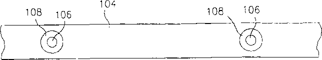
As shown in Figure 4, the forming plastic articles 66 of formation does not comprise the gate vestiges 68 with minimum thickness 70 and width 72 substantially.
In the embodiment of Fig. 5 A, shorter single chopper switch 74,76 is only driven to open and close single jet pipe 78,80 from a side by single cylinder 82,84 respectively individually.Fig. 5 B and 5C have shown the vertical view of the single chopper switch 74,76 that has hole 86,88.Shorter single chopper switch has less flexibility, and is easy to only from a side drive.
Fig. 6 A has shown another compact embodiment of single chopper switch 90, and single chopper switch 90 is walked around running roller 92,94 and driven by cylinder 96,98.In Fig. 6 A, do not show other parts.The advantage of this driving method is: piston is perpendicular to the injection molding defiber, and this will reduce the size of injection molding.
Fig. 6 B has shown the embodiment that another is compact, and wherein, single chopper switch 90 is walked around running roller 92,94 and driven by cylinder 96,98.In this embodiment, three injection jet pipes 101,103 and 105 are arranged, be used for molten material is injected single, a big arc die cavity space 107 by three isolated injection molding cast gates 115.Chopper switch 90 has three holes 109,111 and 113, is used for aiming at so that molten material flows into die cavity space 107 simultaneously with the outlet of injection jet pipe 101,103 and 105 and corresponding injection molding cast gate 115.This can be used for having the large component of radian, for example, and bumper.
Fig. 7 A-7D has shown other chopper switch structure.Fig. 7 A is the vertical view that has the chopper switch 104 in hole 106, and Fig. 7 B is its side view, each opening be lined be different from the chopper switch material a kind of material 108 to obtain different characteristics.
Fig. 7 C and 7D are vertical view and the side views that has the chopper switch 110 in hole 112, comprise dividing plate 114 in the hole 112 to form branch hole in, and it can be used for injecting more than one material in a single die cavity.
In the embodiment of Fig. 8, be contained in by the pinion (not shown) move tooth bar 118 on framework 116 on a plurality of chopper switches 120 are housed, they can move forward and backward with framework, are used for a plurality of injection moldings.
Fig. 9 A-9D has shown the employing mechanical device, and for example, as the friction gearing of motor 130,132, rather than Pneumatic component drives the different institutions of the chopper switch 122,124 with hole 126,128.
The embodiment of Figure 10 has shown jet pipe 134 and nozzle exit 137 and 139 with two passages 136,138 that are respectively applied for different plasticity materials A and B.Chopper switch 140 has a single opening 142.Mobile chopper switch 140 so that hole 142 primary importance and outlet 137 and injection molding cast gate 143 is aimed at and on the second place with export 139 and injection molding cast gate 143 aim at.Chopper switch 140 be moved further so that hole 142 with outlet 137 or export 139 misalignment.This structure can injection material A, injection material B then.Chopper switch 140 can adopt above-mentioned any mechanism to move.In addition, chopper switch 140 also can be located so that materials A and B inject injection molding cast gate 143 simultaneously through via hole 142.In most of application scenarios, a kind of material forms core, and another kind of material forms the top layer part.In the prefabricated component application scenario, a kind of material may be unworn PET, and another kind of material may be the PET that reclaims.
Replace a chopper switch, valve leaves gating apparatus and can be one and open the cast gate disk, as shown in figure 11.As previously mentioned, opening cast gate disk 150 is installed between a nozzle exit 154 and the injection molding cast gate (not shown).Open cast gate disk 150 one or more holes 152 can be arranged.The quantity in hole 152 depends on and opens the nozzle exit that cast gate disk 150 cooperates and the quantity of injection molding cast gate.When disk 150 has a plurality of hole 152, the hole can be used for to single injection jet pipe valve open cast gate or give a more than jet pipe simultaneously valve open cast gate.In addition, when disk 150 had a plurality of hole 152, can there be different sizes in the hole.The diameter of opening cast gate disk 150 is by the nozzle exit that must cooperate with it and the structures shape of injection molding cast gate.
In operation, opening cast gate disk 150 preferably rotates between the primary importance and the second place, in primary importance, hole 152 is aimed at so that molten plastic material flows to the die cavity space from nozzle exit through the injection molding cast gate with nozzle exit and injection molding cast gate, in the second place, hole 152 and nozzle exit and the misalignment of injection molding cast gate.Any appropriate device (not shown) of the prior art is used in to rotate between the primary importance and the second place opens cast gate disk 150.A qualification gap between each injection nozzle exit and injection molding cast gate can allow parts 150 to rotate but can the seepage molten plastic material.
The thickness of disc-shaped part 150 is determined by the equation of front.Disc-shaped part 150 is that enough thin so that these parts do not have plastic material entrained and do not have plastic material sheet blank to form in hole 152 by disc-shaped part between the primary importance and the second place substantially in the moving process.In this manner, can not waste molten plastic material.Do not have plastic material to flow between the parts yet and can not disturb the operation of disc-shaped part.
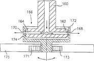
Figure 12 has shown another embodiment of the present invention, and it is used for driving cast gate jet pipe 160 valves to a side direction and opens cast gate, and jet pipe 160 has one or more outlets vertical with the molten material main flow 162,164.In this embodiment, the cup-shaped cast gate parts 166 of opening that gating apparatus comprises a rotation left by valve.As shown in figure 12, open cast gate parts 166 and be included in hole 168 and 170 on sidewall 172 and 174.Each hole 168 and 170 is connected with 162 and 164 and injection molding cast gate (not shown)s of outlet.
Opening cast gate parts 166 preferably rotates between the primary importance and the second place, in primary importance, hole 168,170 and nozzle exit 162 and 164 and the injection molding cast gate aims at so that molten plastic material flows to the die cavity space from nozzle exit through the injection molding cast gate, in the second place, hole 168,170 and nozzle exit 162,164 and the misalignment of injection molding cast gate.Any appropriate device (not shown) of the prior art is used in to rotate between the primary importance and the second place opens cast gate parts 166.For example, can provide an elongated driving supporting plate 175 that has section of rack 173.Section of rack 173 with one with open pinion 171 engagements that cast gate parts 166 are connected.The suitable components (not shown) is connected so that it moves forward and backward with supporting plate 175, thereby rotates out cast gate parts 166 through the action of tooth bar 173 and pinion 171.In a multi-cavity injection molding, each jet pipe 160 by one open 160 of cast gate parts around, and drive supporting plate 175 and will cooperatively interact with each pinion 171 of opening cast gate parts 166.Between each injection nozzle exit and injection molding cast gate one limits spacing can allow to hold that cast gate parts 166 rotate and can the seepage molten plastic material.
The thickness of each sidewall 172,174 is determined by the equation of front.Each sidewall is enough thinly not have plastic material entrained and do not have plastic material sheet blank to form in hole 168 and 170 by sidewall between the primary importance and the second place in the moving process substantially so that open cast gate parts 166.In this manner, can not waste molten plastic material.Do not have plastic material to flow between the parts yet and can not disturb the operation of holding cast gate parts 166.
Have been found that valve of the present invention opens pouring gate structure and be injected into a die cavity space to form multiple material article at multiple material, in multiple prefabricated the injection molding system shown in Figure 18 and 21 special application is arranged.Referring now to Figure 13, it illustrates an injection molding system 200 that can form the article of being made up of three kinds of different materials.System 200 is in U.S. Patent No. 4,863, is described in 665, and this patent is introduced as a reference.System 200 comprises three molten material sources, i.e. extruder A, B and C.Represent with solid line that from the hot runner system part that extruder B draws the components of system as directed that originates from extruder C dots, originate from the components of system as directed of extruder A and represent with dotted line.In general operation, be used to form first kind of material on exterior surface from extruder A, for example, original PET at first injects die cavity space 204.Subsequently, from second kind of material of extruder C, for example, the EVOH insulating resin is injected into die cavity space 204.Then, from the third material of extruder B, for example, reground PET or any other required potting resin are injected into die cavity space 204.
Extruder B provides molten material B to a heated manifold 206, and this manifold communicates with injection jet pipe 202 through hot runner or passage 210,212,214 and 216 respectively.Reference numeral 218,220,222 and 224 expression guiding valves are operated it and can be controlled the injecting jet jar or inject cylinder 226,228,230 and 232.
Accordingly, the hot manifold 234 of second kind of material C of supply is drawn through hot runner or passage 236,238,240 and 242 to each jet pipe 202 from extruder C.Guiding valve 244,246,248 and 250 control injecting jet jars 252,254,256 and 258.
Supplying the hot manifold 260 of the third materials A draws through hot runner 262,264,266 and 268 directly to each jet pipe 202 from extruder A.
Three kinds of materials are fed in the operating in of system ' No. 665 patents of jet pipe 202 and have carried out more detailed explanation, at this, repetition of explanation no longer.
Referring to Figure 14, the injection jet pipe comprises three passages 270,272 and 274 that are respectively applied for materials A, B and C.Passage 270,272 and 274 ends in opening 276,278 and 280 respectively.In addition, the center line spacing distance D of the center line of passage 270 and passage 272
AB, the center line spacing distance D of the center line of passage 272 and passage 274
AC
This system also comprises an injection molding cast gate 282, is used to make molten material to flow into die cavity space 204.
But system 200 is different from No.4, and the system in 863,665 United States Patent (USP)s is because it comprises that a valve that is displaced sideways according to the present invention opens cast gate chopper switch 284.Shown in Figure 14 and 15, chopper switch 284 be installed in the injection nozzle exit 276,278 and 280 and injection molding cast gate 282 between.As previously mentioned, enough thin of chopper switch 284 do not have molten material to be carried by it so that open in the moving process of cast gate chopper switch 284 at valve substantially.
Chopper switch 284 can have a hole 286 and be used for each injection jet pipe 202.Chopper switch can be displaced sideways by the cylinder (not shown), so that each hole 286 is sequentially aimed at the outlet 276,278 and 280 in each injection jet pipe 202.An operable order is used for making each hole 286 to aim at so that materials A is fed injection molding cast gate 282 with outlet 278, delivers to the die cavity space then.Subsequently, each hole 286 moves to and exports 276 and aim at so that material B feeds die cavity space 204 through injection molding cast gate 282.Then, each hole 286 is aimed at so that material C feeds die cavity space 204 through injection molding cast gate 282 with outlet 280.At last, chopper switch 284 can move to a position, and in this position, each hole 286 is not aimed at any one outlet 276,278 and 280 in each injection jet pipe 202, and molten material is interrupted to the mobile of die cavity space 204.
As shown in figure 16, cast gate chopper switch 284 left by valve can have by the distance D of determining
ABAnd D
ACThree holes 290,292 at interval and 294 part, this both can realize that above-mentioned injection order also can be achieved as follows order: injection C/ injects A+B or injects A+B/ and inject C or sequentially inject A-B-C.
Figure 17 illustrates the another kind of injection molding cast gate 282 ' that can use with the injection jet pipe of Figure 14.As shown in the figure, injection molding cast gate 282 ' can have respectively and outlet 276,278 and 280 three passages 300,302 and 304 of aiming at.
Figure 18 has shown that the system that can adopt Figure 13-16 makes three kinds prefabricated of forming by materials A, B and C.
With reference to Figure 19, this figure illustrates an injection jet pipe 134 ' that is used to inject two kinds of materials A and B.Injection jet pipe 134 ' is similar with the injection jet pipe among Figure 10, and it has the passage 136 ' and 138 ' of outlet of ending in 137 ' and 139 '.Materials A and B through export 137 ' and 139 ' and injection molding cast gate 143 ' feed a die cavity space.As previously mentioned, cast gate chopper switch 140 ' left by valve a hole 142 ' that materials A and B are injected in proper order.Shown in Figure 19 and 20, chopper switch 140 ' also can have a part with two holes 310 and 312 so that materials A and B inject simultaneously.This structure can be used to finish following injection order: (1) is injected A/ and is injected A+B; (2) inject B/ and inject A+B.Valve leaves cast gate chopper switch 140 ' and can be used for finishing other order.Can adopt two kinds prefabricated of cast gate valve arrangement manufacturing of opening of Figure 19 and 20 to be presented among Figure 21.
There are some resin materials in injection process, to need other heat and better temperature control.In this case, need open pouring gate structure to valve a heater and a thermocouple are installed.Although these will discuss how do i in the context of one of the foregoing description, what should be familiar with is: heater and thermocouple structure can be included in any one valve described here and open in the pouring gate structure.
Referring to Figure 22, a side direction valve is opened cast gate chopper switch 48 and on its surface heater 320 is housed, for example, and a thin slice heater and a thermocouple 322.Heater 320 can be used to guarantee that resin material receives it and injected required heat suitably.Thermocouple 322 can be measured near the temperature the hole 46, thereby makes injected system realize the better purpose of control temperature.Thermocouple can be any suitable thermocouple in the prior art, for example, and a thin slice thermocouple.Heater 320 and thermocouple 322 can be installed on the surface of chopper switch 48 with any suitable manner of the prior art.
Referring to Figure 23 A-23C, replace to use a single valve to open the cast gate chopper switch, need use two chopper switches 340 and 342 that can move in the opposite direction for some application scenarios.As shown in the figure, chopper switch 340 and 342 has a hole 344 and 346 respectively.Chopper switch 340 and 342 can 344 and 346 misalignment from the hole primary importance (Figure 23 B) move to hole 344 and 346 second places (Figure 23 C) of aiming at so that flow into a die cavity space (not shown) from the material of an injection jet pipe 348.Any appropriate device (not shown) of the prior art can be used for mobile chopper switch 340 and 342 between the primary importance and the second place.What can believe is: this method at the optimum thickness of selecting chopper switch in case form and provide more flexibility aspect the sheet blank.
Although shown multiple chopper switch structure, also can use the chopper switch shown in Figure 24 A-24C with a plurality of thickness T and Tmin with constant thickness.This is because in some application scenarios, just just needs thickness limit Tmin in case form the sheet blank near injection molding cast gate and its hole 400.In this structure, select one first thickness T so that chopper switch 48 ' has enough intensity and avoids making its bending in being displaced sideways process.The second thickness T min that must be used for avoiding forming the sheet blank is positioned near each injection molding gate orifice 400 the chopper switch part.These parts with thickness T min of chopper switch 48 ' comprise chopper switch hole 50 ' and 52 '.As previously mentioned, select second thickness in case form the sheet blank.It also can change the function of injection parameter or moulding material.
From Figure 24 A and C as can be seen, the length L of thickness T min is greater than the width M of gate orifice 400.So just formed a space 402, it is a bit larger tham the diameter D of hole 50 ' and 52 ', thereby makes chopper switch 48 ' move to a valve closed position from a valve open position.At the valve open position, molten material can flow through nozzle exit 404 and flow into die cavity space 406 through injection molding gate orifice 400; In the valve closed position, the mobile of molten material is interrupted, and do not have any seepage behind each implantation step.Preferably referring to Figure 24 B, because a gap 402 need be provided, the mid point of length L has all been departed from hole 50 ' and 52 '.
It should be understood that the present invention is not limited to illustrating of describing and show here, these explanations have illustrated just and have realized best mode of the present invention that the shape of parts, size and structure and operation details can be made amendment.The present invention includes and drop on main points and the interior all modifications of scope that claim limits.
Claims (38)
1. device that is used to form molded articles, it comprises:
At least one injection molding (12), the injection molding cast gate (44,46) that it has a die cavity space (32,34) and is communicated with described die cavity space;
An injection jet pipe (24,26) is used at least a molten material liquid stream is supplied to described at least one injection molding the nozzle exit that has at least one and described injection molding cast gate to aim at substantially on the described injection jet pipe;
Movably gating apparatus (48,74,76,90,104,110,120,140,284,140 ', 48 ', 150,166) left by valve, and at least one hole (50,52,86,88,106,112,126,128,142,152,168,170,286,290,292,294,310,312,346,344,50 ', 52 ') is also arranged between injection molding cast gate and at least one nozzle exit thereon;
Be used between the primary importance and the second place, moving the device (56,58,82,84,96,98,171,173,130,132) that described valve is opened gating apparatus, in primary importance, described at least one hole is communicated with described at least one nozzle exit and described injection molding cast gate so that molten material flows to described injection molding cast gate from described at least one outlet, in the second place, interrupted molten material and flowed to described injection molding cast gate from described at least one outlet; And
The thickness that described valve is opened gating apparatus is from 0.01mm to 2mm, thereby described valve is opened gating apparatus between the described primary importance and the second place in the moving process, and there do not have material to be opened gating apparatus by described valve substantially to be entrained and do not have remaining waste material to form.
2. device as claimed in claim 1 is characterized in that: described valve is opened gating apparatus and is had a thickness T min who is limited by following equation:
Tmin=4Vmin/(πD
2)
Wherein, Tmin=minimum thickness;
The minimum volume in Vmin=hole; With
The diameter in D=hole.
3. device as claimed in claim 1 is characterized in that: described valve is opened gating apparatus and is comprised a chopper switch (48,74,76,90,104,110,120,140,284,140 ', 48 ') that has described at least one hole on it.
4. device as claimed in claim 3 is characterized in that: described chopper switch (48,74,76,90,104,110,120,140,284,140 ', 48 ') can with the vertical substantially direction of injection molding cast gate on side direction slide.
5. device as claimed in claim 1, in described die cavity, form plastic articles (60), the part of described article (68) is opened gating apparatus with described valve and is contacted, it is characterized in that: opening the described article section that gating apparatus contacts with described valve is flat substantially, and in described article, can not form joint line substantially, thereby in the close zone of injection molding cast gate of molded articles, not have degree of crystallinity to produce substantially.
6. device as claimed in claim 4 comprises a qualification gap between injection jet pipe and injection molding, and this gap allows chopper switch to slide but can the seepage plastic material.
7. device as claimed in claim 1 is characterized in that: each hole (106) are lined with the different material (108) of material that a kind of and valve are opened gating apparatus.
8. device as claimed in claim 1 is characterized in that: each hole (112) comprise that a dividing plate (114) therein is to provide branch hole in.
9. device as claimed in claim 4 comprises a plurality of chopper switches (120) by a framework (116) supporting.
10. device as claimed in claim 1 also comprises:
A plurality of injection jet pipes (101,103,105) are used for molten material is injected in the die cavity space (107), and each described injection jet pipe has an outlet;
Described valve is opened gating apparatus and is comprised a flexible chopper switch (90) with a plurality of holes (109,111,113); And
Each described hole is aimed at so that described molten material flows into described die cavity space from described injection jet pipe with described each outlet in primary importance.
11. device as claimed in claim 1 is characterized in that: described valve is opened gating apparatus and is comprised two chopper switches (340,342) that can move in the opposite direction, and each described chopper switch has a hole (344,346) thereon.
12. device as claimed in claim 1 also comprises:
Each described injection jet pipe (134,134 ', 202) has a plurality of passages (136,138,136 ', 138 ', 270,272,274), is used to accept the multiple material that will be molded;
Each described passage ends in an outlet; And
Described injection molding cast gate (282 ') is useful on a plurality of passages (300,302,304) that cooperate with described outlet.
13. device as claimed in claim 1 is characterized in that: described valve is opened gating apparatus and is comprised a chopper switch that has the lateral sliding in a hole on it, and described chopper switch is slidably so that order is injected described material.
14. device as claimed in claim 1, it is characterized in that: described valve is opened gating apparatus and is comprised a lateral sliding chopper switch (284,140 ') that has a more than hole (290,292,294,310,312,142 ') on it, the removable so that order of described chopper switch and inject described material simultaneously.
15. device as claimed in claim 1, it is characterized in that: described valve is opened gating apparatus and is comprised device (320) and device (322), device (320) is used for heating described molten material when described molten material flows through described at least one hole, installs the temperature that (322) are used to detect the described molten material that flows through described at least one hole.
16. device as claimed in claim 15, it is characterized in that: described valve is opened gating apparatus and is comprised a chopper switch (48) with at least one hole (46), and described heater and checkout gear are installed on the surface of described chopper switch near each described hole.
17. device as claimed in claim 1 is characterized in that: described valve is opened gating apparatus and is comprised a disk (150) with at least one described hole (152), and described disk can move between described first and second positions rotationally.
18. device as claimed in claim 1, it is characterized in that: the injection jet pipe comprises a plurality of outlets (162,164) vertical substantially with the described molten material main flow that flows through described injection jet pipe, described valve is opened gating apparatus and is comprised a revolving part (166) that has with the same number of hole of outlet (168,170) number, and is used to rack-and-pinion device (171,173) that described revolving part is rotated between described first and second positions.
19. device as claimed in claim 1, it is characterized in that: valve leaves gating apparatus and comprises a chopper switch (48 '), described chopper switch has the first of first thickness that is enough to prevent substantially its bending and at least one to have the second portion of second thickness, second thickness be enough thin so that described chopper switches between the described primary importance and the second place when mobile, do not have material entrained and do not have residual waste to form substantially by described chopper switch.
20. device as claimed in claim 19 also comprises:
Each described second portion has a hole (50 ' 52 '), is used for cooperating with the opening (400) of each injection molding cast gate;
Described hole has a diameter (D);
Each described second portion has a length (L), length (L) greater than the width of each injection molding cast gate to form a gap (402); And
Described gap is greater than the described diameter in described hole.
21. one kind is used for the injection molding article and does not have the method for waste material substantially, it comprises the steps:
At least a molten material is flow through the die cavity space (32,34) that an injection molding cast gate of aiming at at least one nozzle exit substantially supplies to an injection molding (12) from an injection jet pipe (24,26) through at least one nozzle exit;
Thin by between injection molding cast gate and described at least one nozzle exit, installing one, movably and thereon have a hole (50,52,86,88,106,112,126,128,142,152,168,170,286,290,292,294,310,312,346,344,50 ', 52 ') valve is opened gating apparatus (48,74,76,90,104,110,120,140,284,140 ', 48 ', 150,166,340,342), and between the primary importance and the second place, move described valve and open the waste that gating apparatus is eliminated molten material in the molding process substantially, in primary importance, described hole is connected with described at least one nozzle exit and injection molding cast gate so that molten material flows to described injection molding cast gate from described at least one outlet, in the second place, interrupted from described at least one nozzle exit to the flowing of described injection molding cast gate, and described valve is opened and is opened gating apparatus without any described molten material by described thin valve in the moving process of gating apparatus between described first and second positions and transmit.
22. method as claimed in claim 21, it is characterized in that: the chopper switch valve (48,74,76,104,110,120,140,284,140 ', 48 ') that provides to have a hole is provided described installation steps, and described mobile step comprises the described chopper switch valve of lateral sliding.
23. method as claimed in claim 21 comprises by following equation and determines that described valve opens the thickness T min of gating apparatus:
Tmin=4Vmin/(πD
2)
Wherein, Tmin=minimum thickness;
The minimum volume in Vmin=hole; With
The diameter in D=hole.
24. method as claimed in claim 22 is included on vertical with the injection molding cast gate substantially direction side direction described chopper switch that slides.
25. method as claimed in claim 21, plastic articles does not have degree of crystallinity ground to form in the injection molding gate area substantially.
26. method as claimed in claim 21, a part (68) that forms plastic articles (60) and described article in described die cavity space is opened gating apparatus with described valve and is contacted, it is characterized in that: opening the described article section that gating apparatus contacts with described valve is flat substantially, and does not have joint line to form in described article substantially.
27. method as claimed in claim 21 is included in and forms a step that limits the gap between injection jet pipe and the injection molding, this gap allows valve to hold that gating apparatus moves and can the seepage plastic material.
28. method as claimed in claim 21, it is characterized in that: described installation steps are included in the disk (150) with at least one hole (152) are installed between described nozzle exit and the described injection molding cast gate, and described mobile step is included in and rotates described disk between described first and second positions.
29. method as claimed in claim 21 also comprises:
Described injection jet pipe (160) has a plurality of outlets (162,164);
The revolving part (166) that provides one to have hole (168, the 170) number identical with described outlet number is provided described installation steps; And
Described mobile step is included in and rotates described rotary part between described first and second positions.
30. method as claimed in claim 21 also comprises:
An injection jet pipe (202,134,134 ') is provided, and it has a plurality of passages that are used to accept the different materials that will be molded, and each passage ends in a nozzle exit;
Described installation steps are included between injection molding cast gate and the described nozzle exit installs one and has single hole (142,286), chopper switch valve (284,140,140 ') thin, that can be displaced sideways; And
By moving described chopper switch successively with between the position that described different outlet is aimed at, described different materials is sequentially supplied to described injection molding cast gate in described hole.
31. method as claimed in claim 21 also comprises:
An injection jet pipe (202,134 ') is provided, and it has a plurality of passages that are used to accept the different materials that will be molded, and each passage ends in a nozzle exit;
Described installation steps are included between injection molding cast gate and the described nozzle exit installs one and has a plurality of holes (290,292,294,310,312,142 '), chopper switch valve (284,140 ') thin, that can be displaced sideways; And
By moving described chopper switch successively with between the position that one of described different outlet is aimed at, described different materials is sequentially supplied to described injection molding cast gate in one of described hole.
32. method as claimed in claim 31 also comprises:
By described chopper switch being moved to a plurality of positions of aiming at of a plurality of (310,312) and described outlet in the described hole, different materials is supplied to described injection molding cast gate simultaneously.
33. a system that is used for a plurality of article of injection molding comprises:
A plurality of die cavities space (204);
There is an injection molding cast gate (143,143 ', 282,282 ') in each described die cavity space;
Be used at least two kinds of molten materials (A, B, C) are supplied to through described injection molding cast gate the device (134,134 ', 202) in each described die cavity space;
Movably gating apparatus (140,140 ', 284) left by valve between each described injection molding cast gate and described charging gear;
Described movably valve is opened gating apparatus and is had a plurality of holes (142,142 ', 286,310,312);
Be used between at least one open position and a closed position, moving the device (56,58) that described valve is opened gating apparatus; At open position, described hole is communicated with described injection molding cast gate so that at least a described molten material flows to each described die cavity space, and in the closed position, described molten material is to mobile being interrupted in described die cavity space; And
It is enough approaching so that described valve is opened in the moving process of gating apparatus between described position that described valve is opened gating apparatus, and there do not have molten material to be opened gating apparatus by described valve substantially to be entrained.
34. system as claimed in claim 33 is characterized in that: described valve is opened the chopper switch that gating apparatus comprises a plurality of holes thereon.
35. system as claimed in claim 33, it is characterized in that: charging gear comprises a plurality of injection jet pipes, each described injection jet pipe has at least two passages (136,138,136 ', 138 ', 270,272,274), is used to accept at least two kinds of different materials; It also comprises a plurality of extruders (A, B, C), and described extruder is communicated with each described injection jet pipe (202) by the hot runner passage, and each described extruder is with a kind of each the described injection jet pipe that is supplied in the described material.
36. system as claimed in claim 35 is characterized in that: every kind of described material is opened the described hole of gating apparatus and is sequentially fed described die cavity space by being arranged in described valve.
37. system as claimed in claim 35 is characterized in that: every kind of described material is opened the described hole of gating apparatus (290,292,310,312) and is side by side fed described die cavity space by being arranged in described valve.
38. system as claimed in claim 35, it is characterized in that: each described injection jet pipe has two passages (136,138,136 ', 138 ', 270,272,274) that are used to accept two kinds of different materials, and each passage ends in each nozzle exit (137,139,137 ', 139 ', 276,278,280).
Applications Claiming Priority (3)
| Application Number | Priority Date | Filing Date | Title |
|---|---|---|---|
| US4445497P | 1997-03-20 | 1997-03-20 | |
| US60/044,454 | 1997-03-20 | ||
| PCT/US1998/004285 WO1998041378A1 (en) | 1997-03-20 | 1998-03-06 | Process and apparatus for forming plastic articles |
Publications (2)
| Publication Number | Publication Date |
|---|---|
| CN1222879A CN1222879A (en) | 1999-07-14 |
| CN1102493C true CN1102493C (en) | 2003-03-05 |
Family
ID=21932486
Family Applications (1)
| Application Number | Title | Priority Date | Filing Date |
|---|---|---|---|
| CN98800455A Expired - Fee Related CN1102493C (en) | 1997-03-20 | 1998-03-06 | Process and apparatus for forming plastic articles |
Country Status (11)
| Country | Link |
|---|---|
| US (4) | US6056536A (en) |
| EP (1) | EP0936964B1 (en) |
| JP (1) | JP4125792B2 (en) |
| KR (1) | KR100296953B1 (en) |
| CN (1) | CN1102493C (en) |
| AT (1) | ATE366649T1 (en) |
| AU (1) | AU713087B2 (en) |
| CA (1) | CA2255613C (en) |
| DE (1) | DE69838058T2 (en) |
| HK (1) | HK1020030A1 (en) |
| WO (1) | WO1998041378A1 (en) |
Families Citing this family (40)
| Publication number | Priority date | Publication date | Assignee | Title |
|---|---|---|---|---|
| ATE224284T1 (en) * | 1998-02-19 | 2002-10-15 | Husky Injection Molding | CLOSURE GATE DEVICE AND INJECTION MOLDING METHOD |
| US6289259B1 (en) * | 1998-10-16 | 2001-09-11 | Husky Injection Molding Systems Ltd. | Intelligent hydraulic manifold used in an injection molding machine |
| FR2784657B1 (en) * | 1998-10-19 | 2000-11-17 | Cebal | MULTI-LAYERED HEAD TUBE AND MANUFACTURING METHOD |
| EP2273064A1 (en) * | 1998-12-22 | 2011-01-12 | Weatherford/Lamb, Inc. | Procedures and equipment for profiling and jointing of pipes |
| US6454558B1 (en) | 1999-08-23 | 2002-09-24 | Jobst U. Gellert | Melt transfer system |
| AU1071801A (en) | 1999-09-30 | 2001-04-30 | Textron Automotive Company Inc. | Method and apparatus for molding plastic materials with a metallic appearance |
| US6398542B1 (en) * | 2000-05-01 | 2002-06-04 | Husky Injection Molding Systems, Ltd. | Sliding valve gate with inserts |
| US20020043389A1 (en) * | 2000-09-29 | 2002-04-18 | Selvarajan Murugan | Virtual gate design for thin packages |
| US20030008034A1 (en) * | 2001-07-06 | 2003-01-09 | Husky Injection Molding, Ltd. | Method and apparatus for injection molding articles |
| US6648075B2 (en) | 2001-07-13 | 2003-11-18 | Weatherford/Lamb, Inc. | Method and apparatus for expandable liner hanger with bypass |
| GB0130849D0 (en) * | 2001-12-22 | 2002-02-06 | Weatherford Lamb | Bore liner |
| CA2428738C (en) * | 2002-05-16 | 2011-04-26 | Decoma International Inc. | Valve for an injection molding manifold |
| WO2004041505A1 (en) * | 2002-11-06 | 2004-05-21 | Pawel Samotik | Shut-off device and method for hot runner gates |
| GB0315997D0 (en) * | 2003-07-09 | 2003-08-13 | Weatherford Lamb | Expanding tubing |
| DE102004057284A1 (en) * | 2004-11-26 | 2006-06-14 | Fev Motorentechnik Gmbh | Lightweight piston for thermally highly stressed pistons |
| US20060186575A1 (en) * | 2005-02-24 | 2006-08-24 | Prskalo Bill Z | Multi-material mold and method of making multi-material parts |
| US20060222730A1 (en) * | 2005-04-01 | 2006-10-05 | Barth David M | Hot edge diaphragm gate for injection mold |
| US7291007B2 (en) | 2005-04-07 | 2007-11-06 | Freudenberg-Nok General Partnership | Valve ring gate for thermoplastic and thermoset injection molding |
| US7341094B2 (en) * | 2005-05-02 | 2008-03-11 | Husky Injection Molding Systems Ltd. | Metallic alloy slurry dispenser |
| CA2617591C (en) | 2005-08-30 | 2013-10-22 | Advanced Plastics Technologies Luxembourg S.A. | Methods and systems for controlling mold temperatures |
| DE102007027548B4 (en) * | 2006-06-16 | 2015-11-12 | Mold-Masters (2007) Limited | Injection molding device with shut-off valve for individual mold cavities |
| US7803306B2 (en) * | 2006-06-16 | 2010-09-28 | Mold-Masters (2007) Limited | Individual cavity shut-off valve for an injection molding apparatus |
| US7458806B2 (en) * | 2006-06-26 | 2008-12-02 | Freudenberg-Nok General Partnership | Waste-less injection molding fan gate |
| US20080093772A1 (en) * | 2006-10-06 | 2008-04-24 | Graham Packing Company, Lp | Method and apparatus for delivering sequential shots to multiple cavities to form multilayer articles |
| US7658606B2 (en) * | 2006-12-22 | 2010-02-09 | Mold-Masters (2007) Limited | Edge gated injection molding apparatus |
| ATE544573T1 (en) * | 2006-12-29 | 2012-02-15 | Mold Masters 2007 Ltd | INJECTION MOLDING DEVICE WITH SIDE GATE OPENING |
| US20080277839A1 (en) * | 2007-05-07 | 2008-11-13 | Plastic Molded Technologies, Inc. | Co-Injection Molding System, Method of Injection Molding a Composite Structure and Article Formed Thereby |
| US7854876B2 (en) | 2007-05-25 | 2010-12-21 | Ecovision Technologies, Llc | Apparatus and methods for modular preform mold system |
| JP4968202B2 (en) * | 2008-07-10 | 2012-07-04 | 株式会社デンソー | Manifold apparatus for injection mold and injection molding method |
| KR101022748B1 (en) * | 2009-09-08 | 2011-03-17 | 한국기계연구원 | Injection molding apparatus for oscillating filling and packing |
| KR101330428B1 (en) * | 2010-12-31 | 2013-11-15 | 허남욱 | Nozzle device for injection molding |
| JP5829338B2 (en) * | 2011-10-11 | 2015-12-09 | ボレアリス・アクチェンゲゼルシャフトBorealis Ag | Dispensing system for injection molding, injection molding system having the same, and injection molding method |
| US20130214450A1 (en) | 2012-02-17 | 2013-08-22 | Apple Inc. | Method and apparatus for molding parts |
| CN102642272A (en) * | 2012-04-07 | 2012-08-22 | 金孝禹 | Material closing device for injection molding machine |
| ITUA20163072A1 (en) * | 2016-05-02 | 2017-11-02 | Inglass Spa | PROCESSING AND INJECTION MOLDING EQUIPMENT OF PLASTIC MATERIALS |
| US11007687B2 (en) | 2017-10-02 | 2021-05-18 | Legacy Foam Llc | Polyurethane injection system and method |
| CN109435302B (en) * | 2018-10-31 | 2020-07-14 | 重庆市惠美实业有限公司 | Training shoe sole forming machine |
| GB201905182D0 (en) * | 2019-04-11 | 2019-05-29 | Obrist Closures Switzerland | Valve |
| WO2022075917A1 (en) * | 2020-10-07 | 2022-04-14 | Meiban International Pte Ltd | Anti-drool cold deck for high consistency silicone rubber |
| JP2023180507A (en) * | 2022-06-09 | 2023-12-21 | 世紀株式会社 | Gate structure of mold having built-in hot runner, and mold having built-in hot runner |
Citations (2)
| Publication number | Priority date | Publication date | Assignee | Title |
|---|---|---|---|---|
| US4828480A (en) * | 1986-10-22 | 1989-05-09 | Smith Kenneth J | Sprue bushing with automatically activated gate |
| US4931234A (en) * | 1986-05-12 | 1990-06-05 | Husky Injection Molding Systems Ltd. | Coinjection of hollow articles and preforms |
Family Cites Families (33)
| Publication number | Priority date | Publication date | Assignee | Title |
|---|---|---|---|---|
| DE1296332B (en) * | 1961-10-05 | 1969-05-29 | Desma Werke Gmbh | Injection mold with a lockable sprue channel |
| GB1219097A (en) * | 1967-12-15 | 1971-01-13 | Ici Ltd | Improvements in or relating to injection moulding machines |
| DE1779504B2 (en) * | 1968-08-21 | 1972-05-31 | Eckert & Ziegler Gmbh, 8832 Weissenburg | METHOD FOR PROCESSING HEAT-RESISTANT PLASTICS, IN PARTICULAR THERMAL PLASTICS FROM THE AMINOPLASTIC FAMILY ON INJECTION MOLDING MACHINES |
| US3581341A (en) * | 1969-02-06 | 1971-06-01 | Phillips Petroleum Co | Gate shut-off device for foam molding |
| DE2320346A1 (en) * | 1973-04-21 | 1974-11-07 | Schloemann Siemag Ag | DEVICE FOR THE PRODUCTION OF MOLDED PARTS FROM THERMOPLASTIC PLASTIC |
| US3918870A (en) * | 1974-02-13 | 1975-11-11 | Norton Co | Injection molding machine |
| US4077760A (en) * | 1974-10-03 | 1978-03-07 | National Can Corporation | Injection molding process and apparatus |
| US4073944A (en) * | 1976-07-06 | 1978-02-14 | Cincinnati Milacron Inc. | Nozzle shut-off valve |
| US4108956A (en) * | 1977-01-21 | 1978-08-22 | Owens-Illinois, Inc. | Injection molding method and apparatus |
| US4099904A (en) * | 1977-04-21 | 1978-07-11 | Cincinnati Milacron Inc. | Nozzle shut-off valve for injection molding machine |
| JPS6040366B2 (en) * | 1979-10-19 | 1985-09-10 | 固 青木 | Sprue cutting method and device for bottomed parison |
| JPS5731545A (en) * | 1980-07-31 | 1982-02-20 | Matsushita Electric Works Ltd | Spilling preventor for molding machine |
| US4657496A (en) * | 1984-06-04 | 1987-04-14 | Gifu Husky Co., Ltd. | Hot-runner mold for injection molding |
| JPS6124241A (en) * | 1984-07-13 | 1986-02-01 | Nec Corp | Resin sealing metallic mold of semiconductor device |
| US4701292A (en) * | 1984-09-13 | 1987-10-20 | Husky Injection Molding Systems Ltd. | Method for pressure molding objects of different resins |
| JPS62211119A (en) * | 1986-03-11 | 1987-09-17 | Ishii Kogyo Kk | Shut-off device for injection molding |
| US4863369A (en) * | 1986-05-12 | 1989-09-05 | Husky Injection Molding Systems Ltd. | Injection molding with shooting pots |
| US4717324A (en) * | 1986-05-12 | 1988-01-05 | Husky Injection Molding Systems, Inc. | Coinjection of hollow articles and preforms |
| US4808101A (en) * | 1986-05-12 | 1989-02-28 | Husky Injection Molding Systems Ltd. | Tri-injection of hollow articles |
| US4775308A (en) * | 1986-05-12 | 1988-10-04 | Husky Injection Molding Systems, Ltd. | Nozzle for coinjection of hollow articles and preforms |
| JPS63147619A (en) * | 1986-12-10 | 1988-06-20 | Nec Corp | Punching of bore in resin disk |
| CA1261579A (en) * | 1987-03-19 | 1989-09-26 | Mold-Masters Limited | Replaceable rocker arm assembly for injection molding system |
| US4863665A (en) * | 1987-05-18 | 1989-09-05 | Husky Injection Molding Systems, Ltd. | Tri-injection of hollow articles |
| CA1261571A (en) * | 1987-12-17 | 1989-09-26 | Jobst U. Gellert | Injection molding single nozzle valve gating |
| US4919606A (en) * | 1988-12-21 | 1990-04-24 | Gellert Jobst U | Injection molding rack and pinion valve pin actuating mechanism |
| JPH02289320A (en) * | 1989-04-28 | 1990-11-29 | Nissei Plastics Ind Co | Nozzle device |
| AU630761B2 (en) * | 1989-11-14 | 1992-11-05 | F F Seeley Nominees Pty Ltd | Valve gate manifold |
| US5143733A (en) * | 1991-04-19 | 1992-09-01 | Husky Injection Molding Systems Ltd. | Injection molding apparatus |
| US5112212A (en) * | 1991-05-02 | 1992-05-12 | Husky Injection Molding Systems Ltd. | Shooting pot with combined valve and piston |
| US5200207A (en) * | 1991-06-10 | 1993-04-06 | Husky Injection Molding Systems Ltd. | Hot runner system for coinjection |
| US5499916A (en) * | 1994-10-28 | 1996-03-19 | Husky Injection Molding Systems Ltd. | Rotary actuated gate valve |
| JPH08142122A (en) * | 1994-11-14 | 1996-06-04 | Kobe Steel Ltd | Injection machine for fiber reinforced thermoplastic resin |
| US5922363A (en) * | 1997-04-07 | 1999-07-13 | Dtl Technology Limited Partnership | Molding multi-layered articles using coinjection techniques |
-
1998
- 1998-02-25 US US09/030,593 patent/US6056536A/en not_active Expired - Fee Related
- 1998-03-06 CA CA002255613A patent/CA2255613C/en not_active Expired - Fee Related
- 1998-03-06 JP JP54055598A patent/JP4125792B2/en not_active Expired - Fee Related
- 1998-03-06 EP EP98908958A patent/EP0936964B1/en not_active Expired - Lifetime
- 1998-03-06 WO PCT/US1998/004285 patent/WO1998041378A1/en active IP Right Grant
- 1998-03-06 AT AT98908958T patent/ATE366649T1/en not_active IP Right Cessation
- 1998-03-06 KR KR1019980709380A patent/KR100296953B1/en not_active IP Right Cessation
- 1998-03-06 CN CN98800455A patent/CN1102493C/en not_active Expired - Fee Related
- 1998-03-06 DE DE69838058T patent/DE69838058T2/en not_active Expired - Fee Related
- 1998-03-06 AU AU66861/98A patent/AU713087B2/en not_active Ceased
- 1998-03-06 US US09/036,132 patent/US6146123A/en not_active Expired - Fee Related
-
1999
- 1999-08-20 US US09/372,174 patent/US6149417A/en not_active Expired - Fee Related
- 1999-08-20 US US09/377,996 patent/US6355197B1/en not_active Expired - Fee Related
- 1999-11-11 HK HK99105199A patent/HK1020030A1/en not_active IP Right Cessation
Patent Citations (2)
| Publication number | Priority date | Publication date | Assignee | Title |
|---|---|---|---|---|
| US4931234A (en) * | 1986-05-12 | 1990-06-05 | Husky Injection Molding Systems Ltd. | Coinjection of hollow articles and preforms |
| US4828480A (en) * | 1986-10-22 | 1989-05-09 | Smith Kenneth J | Sprue bushing with automatically activated gate |
Also Published As
| Publication number | Publication date |
|---|---|
| EP0936964B1 (en) | 2007-07-11 |
| HK1020030A1 (en) | 2000-03-10 |
| JP4125792B2 (en) | 2008-07-30 |
| US6056536A (en) | 2000-05-02 |
| AU6686198A (en) | 1998-10-12 |
| WO1998041378A1 (en) | 1998-09-24 |
| JP2001505838A (en) | 2001-05-08 |
| US6149417A (en) | 2000-11-21 |
| DE69838058D1 (en) | 2007-08-23 |
| KR100296953B1 (en) | 2001-10-29 |
| CA2255613A1 (en) | 1998-09-24 |
| KR20000015830A (en) | 2000-03-15 |
| CN1222879A (en) | 1999-07-14 |
| US6355197B1 (en) | 2002-03-12 |
| US6146123A (en) | 2000-11-14 |
| EP0936964A1 (en) | 1999-08-25 |
| EP0936964A4 (en) | 2004-05-26 |
| ATE366649T1 (en) | 2007-08-15 |
| DE69838058T2 (en) | 2008-04-03 |
| CA2255613C (en) | 2008-07-15 |
| AU713087B2 (en) | 1999-11-25 |
Similar Documents
| Publication | Publication Date | Title |
|---|---|---|
| CN1102493C (en) | Process and apparatus for forming plastic articles | |
| US4734243A (en) | Injection molding machine and method | |
| CN101528440B (en) | Injection molding system, computer program, method of injection molding, and injection molding machine | |
| CA2700819C (en) | Process for the production of elongated profiles or ledges out of solidifying molding compounds in a mold and mold | |
| CN1099951C (en) | Valve element driving mechanism for injection moulding equipment | |
| US6491509B1 (en) | Shooting pot actuator for an injection molding machine | |
| CN105451958A (en) | Injection molding flow control apparatus and method | |
| CN87106128A (en) | The manufacturing of article | |
| CN1575953A (en) | Injection molding method and injection molding apparatus | |
| US20080317893A1 (en) | Integrated system for producing composites | |
| RU2007117914A (en) | DEVICE AND METHOD FOR PRODUCING PLASTIC PRODUCTS | |
| CN1863658A (en) | Injection molding valve gate system and activating mechanism | |
| CN102189635A (en) | Multi-axis injection molding apparatus | |
| CA2448129A1 (en) | Tight pitch nozzle with individual valve gate control | |
| CN101754841A (en) | Apparatus and method for forming products | |
| CN217834466U (en) | Differential injection molding equipment for melt of pouring system | |
| KR100966877B1 (en) | Hot Runner System and Injection Molding Method using the same | |
| CN1269624C (en) | Method for controlling injection process and injection unit | |
| CN207224484U (en) | A kind of injection compression moulding mould | |
| CN102802903A (en) | Mold assembly with integrated melting device | |
| CN1968799A (en) | Hot runner device and injection molding device | |
| CN112873723A (en) | Double-material-opening automatic mixing efficient injection molding machine and working method thereof | |
| CN103341954B (en) | A kind of Cold runner rubber vulcanization mould | |
| JP2009000854A (en) | Injection molding device | |
| CN218019805U (en) | Rubber injection moulding device with multi-nozzle structure |
Legal Events
| Date | Code | Title | Description |
|---|---|---|---|
| C06 | Publication | ||
| PB01 | Publication | ||
| C10 | Entry into substantive examination | ||
| SE01 | Entry into force of request for substantive examination | ||
| C53 | Correction of patent of invention or patent application | ||
| CP02 | Change in the address of a patent holder |
Address after: Ontario Applicant after: Husky Injection Molding System Ltd. Address before: American New York Applicant before: Husky Injection Molding System Ltd. |
|
| C14 | Grant of patent or utility model | ||
| GR01 | Patent grant | ||
| C17 | Cessation of patent right | ||
| CF01 | Termination of patent right due to non-payment of annual fee |
Granted publication date: 20030305 Termination date: 20100306 |