CN1102288A - Nanometer metrology - Google Patents
Nanometer metrology Download PDFInfo
- Publication number
- CN1102288A CN1102288A CN94190054A CN94190054A CN1102288A CN 1102288 A CN1102288 A CN 1102288A CN 94190054 A CN94190054 A CN 94190054A CN 94190054 A CN94190054 A CN 94190054A CN 1102288 A CN1102288 A CN 1102288A
- Authority
- CN
- China
- Prior art keywords
- signal
- displacement
- electric signal
- light
- produce
- Prior art date
- Legal status (The legal status is an assumption and is not a legal conclusion. Google has not performed a legal analysis and makes no representation as to the accuracy of the status listed.)
- Pending
Links
- 238000006073 displacement reaction Methods 0.000 claims abstract description 87
- 230000008859 change Effects 0.000 claims abstract description 23
- 238000010897 surface acoustic wave method Methods 0.000 claims description 39
- 239000000523 sample Substances 0.000 claims description 27
- 230000000694 effects Effects 0.000 claims description 22
- 238000000034 method Methods 0.000 claims description 22
- 238000012546 transfer Methods 0.000 claims description 17
- 230000003287 optical effect Effects 0.000 claims description 16
- 239000000758 substrate Substances 0.000 claims description 12
- 238000005259 measurement Methods 0.000 claims description 11
- 230000008569 process Effects 0.000 claims description 2
- 230000002452 interceptive effect Effects 0.000 abstract 1
- 230000010363 phase shift Effects 0.000 description 12
- 230000008901 benefit Effects 0.000 description 5
- 230000009471 action Effects 0.000 description 4
- 238000005516 engineering process Methods 0.000 description 4
- 230000001427 coherent effect Effects 0.000 description 3
- 235000009508 confectionery Nutrition 0.000 description 3
- 238000004519 manufacturing process Methods 0.000 description 3
- 229910013641 LiNbO 3 Inorganic materials 0.000 description 2
- 239000006096 absorbing agent Substances 0.000 description 2
- 238000012937 correction Methods 0.000 description 2
- 238000000609 electron-beam lithography Methods 0.000 description 2
- 238000012545 processing Methods 0.000 description 2
- 239000010453 quartz Substances 0.000 description 2
- VYPSYNLAJGMNEJ-UHFFFAOYSA-N silicon dioxide Inorganic materials O=[Si]=O VYPSYNLAJGMNEJ-UHFFFAOYSA-N 0.000 description 2
- 241000931526 Acer campestre Species 0.000 description 1
- 229910005540 GaP Inorganic materials 0.000 description 1
- 229910020068 MgAl Inorganic materials 0.000 description 1
- 240000007594 Oryza sativa Species 0.000 description 1
- 235000007164 Oryza sativa Nutrition 0.000 description 1
- 239000012814 acoustic material Substances 0.000 description 1
- 230000015572 biosynthetic process Effects 0.000 description 1
- 239000013078 crystal Substances 0.000 description 1
- 230000005611 electricity Effects 0.000 description 1
- 239000011521 glass Substances 0.000 description 1
- CPBQJMYROZQQJC-UHFFFAOYSA-N helium neon Chemical compound [He].[Ne] CPBQJMYROZQQJC-UHFFFAOYSA-N 0.000 description 1
- 230000010287 polarization Effects 0.000 description 1
- 230000009467 reduction Effects 0.000 description 1
- 230000001105 regulatory effect Effects 0.000 description 1
- 235000009566 rice Nutrition 0.000 description 1
- 229910052594 sapphire Inorganic materials 0.000 description 1
- 239000010980 sapphire Substances 0.000 description 1
- 239000004065 semiconductor Substances 0.000 description 1
- 239000007787 solid Substances 0.000 description 1
- 239000002594 sorbent Substances 0.000 description 1
- 238000010561 standard procedure Methods 0.000 description 1
- 230000003068 static effect Effects 0.000 description 1
Images


Classifications
-
- G—PHYSICS
- G01—MEASURING; TESTING
- G01L—MEASURING FORCE, STRESS, TORQUE, WORK, MECHANICAL POWER, MECHANICAL EFFICIENCY, OR FLUID PRESSURE
- G01L23/00—Devices or apparatus for measuring or indicating or recording rapid changes, such as oscillations, in the pressure of steam, gas, or liquid; Indicators for determining work or energy of steam, internal-combustion, or other fluid-pressure engines from the condition of the working fluid
- G01L23/22—Devices or apparatus for measuring or indicating or recording rapid changes, such as oscillations, in the pressure of steam, gas, or liquid; Indicators for determining work or energy of steam, internal-combustion, or other fluid-pressure engines from the condition of the working fluid for detecting or indicating knocks in internal-combustion engines; Units comprising pressure-sensitive members combined with ignitors for firing internal-combustion engines
- G01L23/221—Devices or apparatus for measuring or indicating or recording rapid changes, such as oscillations, in the pressure of steam, gas, or liquid; Indicators for determining work or energy of steam, internal-combustion, or other fluid-pressure engines from the condition of the working fluid for detecting or indicating knocks in internal-combustion engines; Units comprising pressure-sensitive members combined with ignitors for firing internal-combustion engines for detecting or indicating knocks in internal combustion engines
- G01L23/225—Devices or apparatus for measuring or indicating or recording rapid changes, such as oscillations, in the pressure of steam, gas, or liquid; Indicators for determining work or energy of steam, internal-combustion, or other fluid-pressure engines from the condition of the working fluid for detecting or indicating knocks in internal-combustion engines; Units comprising pressure-sensitive members combined with ignitors for firing internal-combustion engines for detecting or indicating knocks in internal combustion engines circuit arrangements therefor
-
- G—PHYSICS
- G01—MEASURING; TESTING
- G01D—MEASURING NOT SPECIALLY ADAPTED FOR A SPECIFIC VARIABLE; ARRANGEMENTS FOR MEASURING TWO OR MORE VARIABLES NOT COVERED IN A SINGLE OTHER SUBCLASS; TARIFF METERING APPARATUS; MEASURING OR TESTING NOT OTHERWISE PROVIDED FOR
- G01D5/00—Mechanical means for transferring the output of a sensing member; Means for converting the output of a sensing member to another variable where the form or nature of the sensing member does not constrain the means for converting; Transducers not specially adapted for a specific variable
- G01D5/48—Mechanical means for transferring the output of a sensing member; Means for converting the output of a sensing member to another variable where the form or nature of the sensing member does not constrain the means for converting; Transducers not specially adapted for a specific variable using wave or particle radiation means
-
- G—PHYSICS
- G01—MEASURING; TESTING
- G01B—MEASURING LENGTH, THICKNESS OR SIMILAR LINEAR DIMENSIONS; MEASURING ANGLES; MEASURING AREAS; MEASURING IRREGULARITIES OF SURFACES OR CONTOURS
- G01B9/00—Measuring instruments characterised by the use of optical techniques
- G01B9/02—Interferometers
- G01B9/02015—Interferometers characterised by the beam path configuration
- G01B9/02023—Indirect probing of object, e.g. via influence on cavity or fibre
-
- G—PHYSICS
- G01—MEASURING; TESTING
- G01B—MEASURING LENGTH, THICKNESS OR SIMILAR LINEAR DIMENSIONS; MEASURING ANGLES; MEASURING AREAS; MEASURING IRREGULARITIES OF SURFACES OR CONTOURS
- G01B9/00—Measuring instruments characterised by the use of optical techniques
- G01B9/02—Interferometers
- G01B9/02097—Self-interferometers
-
- G—PHYSICS
- G01—MEASURING; TESTING
- G01J—MEASUREMENT OF INTENSITY, VELOCITY, SPECTRAL CONTENT, POLARISATION, PHASE OR PULSE CHARACTERISTICS OF INFRARED, VISIBLE OR ULTRAVIOLET LIGHT; COLORIMETRY; RADIATION PYROMETRY
- G01J9/00—Measuring optical phase difference; Determining degree of coherence; Measuring optical wavelength
- G01J9/04—Measuring optical phase difference; Determining degree of coherence; Measuring optical wavelength by beating two waves of a same source but of different frequency and measuring the phase shift of the lower frequency obtained
-
- G—PHYSICS
- G01—MEASURING; TESTING
- G01B—MEASURING LENGTH, THICKNESS OR SIMILAR LINEAR DIMENSIONS; MEASURING ANGLES; MEASURING AREAS; MEASURING IRREGULARITIES OF SURFACES OR CONTOURS
- G01B2290/00—Aspects of interferometers not specifically covered by any group under G01B9/02
- G01B2290/30—Grating as beam-splitter
-
- G—PHYSICS
- G01—MEASURING; TESTING
- G01L—MEASURING FORCE, STRESS, TORQUE, WORK, MECHANICAL POWER, MECHANICAL EFFICIENCY, OR FLUID PRESSURE
- G01L23/00—Devices or apparatus for measuring or indicating or recording rapid changes, such as oscillations, in the pressure of steam, gas, or liquid; Indicators for determining work or energy of steam, internal-combustion, or other fluid-pressure engines from the condition of the working fluid
- G01L23/22—Devices or apparatus for measuring or indicating or recording rapid changes, such as oscillations, in the pressure of steam, gas, or liquid; Indicators for determining work or energy of steam, internal-combustion, or other fluid-pressure engines from the condition of the working fluid for detecting or indicating knocks in internal-combustion engines; Units comprising pressure-sensitive members combined with ignitors for firing internal-combustion engines
- G01L2023/228—Devices or apparatus for measuring or indicating or recording rapid changes, such as oscillations, in the pressure of steam, gas, or liquid; Indicators for determining work or energy of steam, internal-combustion, or other fluid-pressure engines from the condition of the working fluid for detecting or indicating knocks in internal-combustion engines; Units comprising pressure-sensitive members combined with ignitors for firing internal-combustion engines circuit arrangements therefor
Landscapes
- Physics & Mathematics (AREA)
- General Physics & Mathematics (AREA)
- Chemical & Material Sciences (AREA)
- Engineering & Computer Science (AREA)
- Combustion & Propulsion (AREA)
- Spectroscopy & Molecular Physics (AREA)
- Treatment Of Fiber Materials (AREA)
- Measurement Of Mechanical Vibrations Or Ultrasonic Waves (AREA)
- Instruments For Measurement Of Length By Optical Means (AREA)
- Length Measuring Devices Characterised By Use Of Acoustic Means (AREA)
- Investigating Or Analyzing Materials By The Use Of Ultrasonic Waves (AREA)
- Length Measuring Devices With Unspecified Measuring Means (AREA)
Abstract
Apparatus for measuring displacements of an object to nanometer accuracy. This comprises a radio frequency source for a primary electrical signal (50), a transducer (24) for generating an intermediate signal of lesser wavelength at least partly therefrom, a phase shifting means (56) interactive with the intermediate signal and associated with the object in such a way that a displacement of the object causes the phase shifting means (56) to change the path length of the intermediate signal by an amount directly related to the displacement, a phase transference means (60) for generating a secondary electrical signal using, at least partly, the intermediate signal so that the phase of the intermediate signal is transferred to the secondary signal, and a phase detector (62) for measuring the change of phase of the secondary signal relative to the primary on displacement of the object.
Description
The present invention relates to be used for the equipment that is moved to nano-precision and the method for Measuring Object, especially for equipment and the method for making modernized Signal Processing Element.
In the manufacturing of a lot of modernized Signal Processing Elements, need make complicated patterns with height to the precision of micron.These elements comprise SIC (semiconductor integrated circuit), surface acoustic wave (SAW) device, magnetic and optical memory and such as many optical elements of Distributed Feedback Laser, integrated optical device and spatial light modulator.Therefore, producing and measure the ability of the displacement of the equipment that is used to make this element with the precision of micron in the area of several square centimeters of magnitudes, is necessary.In these technology, a kind of trend that miniaturizes the elements is as much as possible arranged, because for example not only can obtain more transistor like this on unit area, and littler transistorized arithmetic speed is faster.Similarly, little feature expansion the frequency range and the fidelity of laser instrument and SAW element.Therefore require in the area of several square centimeters of magnitudes with the nanometer accuracy measurement displacement.
In the past, the sort signal treatment element often utilize mask fabrication equipment and photograph subsequently the reduction and make, this mask fabrication equipment has adopted large-scale high-accuracy mechanical translate stage.More recently, adopted laser interferometer, wherein from the laser beam that is contained in a mirror reflection on the translate stage and a reference laser beam interferes interference to produce a candy strip.Equal half displacement of Wavelength of Laser for translate stage, this candy strip is with mobile one-period.It is to measure easily that the candy strip of the precision of high half to striped moves, so for the typical optical maser wavelength of 500nm, can obtain the precision of 125nm.This precision can be improved to the degree of finally being determined by signal noise ratio by the interpolation between the striped.Laser interferometer for example makes it possible to by adopting the electron beam lithography technology element or the structure that is used on the mask of element are write direct with last size.
One object of the present invention provides a kind of equipment, and it can be with the displacement of height to an object of precision measure of nanometer in several square centimeters zone at least.Further aim of the present invention provides a kind of method, and it can be with the precision of height to nanometer, the displacement of measuring an object on several square centimeters zone at least.
According to a first aspect of the invention, provide the equipment of the displacement that is used to measure an object, it comprises:
A radio frequency (rf) source is used to produce an elementary stable rf electric signal,
A sensing device is used for utilizing at least in part this elementary rf electric signal to produce a M signal, and described M signal has the wavelength less than the wavelength of elementary rf electric signal,
A phase changer, it interacts with this M signal in the use of this equipment and gets in touch with object by this way, promptly make the displacement of object cause this phase changer that the path of this M signal is changed the amount directly related with this displacement
A phase place transfer device, be used for utilizing at least in part the M signal after having an effect with phase changer to produce a secondary stable rf electric signal by this way, promptly make the phase place of M signal of this process effect be passed to this secondary rf electric signal, and
Phase detectors, the phase place that is used to measure secondary rf electric signal when ohject displacement with respect to the change of elementary rf electric signal.
When making object produce a displacement d, before M signal and the effect of phase place transfer device, its path changed one with the direct relevant amount of this displacement.This of path changes d ', make M signal with the phase place transfer device do the time spent phase change equal the phase shift p of 360 * d '/l degree, wherein l is the wavelength of this M signal.The wavelength of this M signal is less than the wavelength from the rf electric signal of wherein deriving, and this M signal is sound or light signal normally, and its phase place is difficult to measure with high precision.Yet the relative phase between two rf signals can be with height to once coming out so that interior precision is measured.This equipment will be delivered to a rf electric signal from the phase shift p of M signal, thereby can come once with interior precision the value of p was measured by measuring the phase change between the primary and secondary rf electric signal when object is subjected to displacement.If can be, then just can measure displacement d with the precision of the l/1800 of l according to equipment of the present invention with for example this phase shift of precision measure p of five/once.Therefore, l is more little, and is just accurate more to the measurement of displacement d.
For example, if this M signal is an acoustic signals, such as wavelength generally at body between the 3000nm to 8000nm or surface acoustic wave, then can with between height to 3000 * 1/1800nm and the 8000 * 1/1800nm-be the precision (supposition d=d ' and phase shift p can measure with height to 1/5th precision once) between 4.4nm and the 1.6nm, the displacement d of object is measured.If this M signal be a light signal and its wavelength generally at hundreds of nm, then can be with height to measuring the displacement of object less than the precision of 1nm.By such as the electron beam lithography technology, the invention enables an element or be used for the zone that structure on the mask of element can directly be written to several square centimeters with last size.
This M signal is light signal preferably, because this makes the precision of measured displacement less than 1nm.In addition, the standard technique from electricity-optical tech also can be used to this equipment.
When this M signal is light signal, sensing device preferably includes the optical signal source and the mixer device that are used to produce light signal, this mixer device is used for light signal and elementary rf electric signal mixed mutually to produce one and obtains first light signal of frequency displacement and not by second light signal of frequency displacement, any one in these two signals can be M signal.The light signal that is chosen as M signal obtains phase shift subsequently, and another light signal be used in as in the phase place transfer device of the local oscillator of M signal to produce secondary rf electric signal.
On principle, this mixer device can have various ways, and for example rf drives integrated light phase or amplitude modulator or integrated optical SSB frequency mixer.Yet, when adopting these devices, be difficult to separate the light signal of frequency displacement and rice frequency displacement.Being more preferably this mixer device is a sound-optical sensor (acousto-optic cell), and wherein body radio frequency sound wave (bulk radiofreguency acoustic wave) is caused by a sonic transducer that is driven by elementary rf electric signal and light signal is introduced into wherein first light signal and undeflected second light signal to produce a deflection.Adopting a sound-optical sensor (acousto-optic cell) is easily as mixer device, because first and second signals have spatially been separated automatically in this device.
When this M signal was light signal, this phase changer is a mirror preferably, and M signal is introduced on this mirror, and this mirror is rigidly secured on this object.If by the reflection that utilizes a mirror path of intermediate light signal is changed, then the displacement d of mirror causes the change 2d of the path of M signal, and thereby the precision of equipment can be doubled.
This phase place transfer device preferably includes one and is used for first and second light signals are carried out mixing producing the device of a difference frequency signal, and this difference frequency signal is this secondary rf electric signal and the phase place of carrying M signal when mixing.Be better it comprise a photodiode be used to make first light signal and second light signal to be mapped on this photodiode with one so that described signal with parallel wavefront and the equitant device of identical polarity.Owing to have only a light signal to experience frequency displacement and have only a light signal to experience phase shift, so the phase place that the difference frequency signal that photodiode produces and elementary rf electric signal are in identical frequency and are carrying M signal.
Perhaps, this M signal can be a rf sound wave, such as a bulk acoustic wave (bulkacoustic wave) or surface acoustic wave (surface wave).When middle signal is the rf sound wave, sensing device comprises that a sound wave medium and one are driven to produce the sonic transducer of rf sound wave (it is a M signal) in the sound wave medium by elementary rf electric signal, and this phase changer is got in touch with the sound wave effect and with object in the use of equipment, so that the displacement of object changes the path by the sound wave of the sound wave medium between sonic transducer and sonic probe, this sonic probe has formed at least a portion of phase place transfer device.The path of the sound wave between sonic transducer and sonic probe, displacement that can be by object is set be with mobile sonic transducer and medium or sonic probe, and obtain changing.This phase changer preferably includes sonic transducer and the medium that is rigidly secured on the object, and this sonic probe is fixed so that the displacement of object make sonic transducer and medium with respect to sonic probe move one with the direct relevant amount of this displacement.
When middle signal is bulk acoustic wave (bulk acoustic wave), the sound wave medium is that a sound-optical sensor and sonic transducer obtain being provided with to cause rf bulk acoustic wave (M signal) in this sound-optical sensor, and the phase place transfer device comprises an optical signal source that produces a light signal (it has formed sonic probe), this light signal is mapped in this sound-optical sensor and with this bulk acoustic wave and has an effect to produce first light signal and second light signal that does not obtain frequency displacement that obtains frequency displacement, this phase place transfer device comprises that further one is used for first and second light signals are carried out mixing producing the device of a difference frequency signal, and this difference frequency signal is exactly secondary rf electric signal.Be used for first and second light signals are carried out mixing to produce this device of a difference frequency signal, can be a photodiode with one be used for first and second light signals are directed on this photodiode so that described signal with the parallel wavefront device overlapping with identical polarity.
First light signal is on the position of having an effect from the light signal of optical signal source and the bulk acoustic wave in sound-optical sensor, with the phase place of portable object sound wave.The phase place of bulk acoustic wave is along with the distance from the ripple of sonic transducer changes continuously.Therefore, if sonic transducer and electricity-optical sensor are with respect to object and rigidly fixedly the time, therefore any displacement of object will change the position of the effect between light signal and the sound wave, and make one of phase change that first light signal carries and the direct relevant amount of this displacement.
For the general rf frequency of about 1GHz, bulk acoustic wave generally has to 8 microns wavelength, thus 1 ° phase shift corresponding to 8 and 22nm between displacement.Therefore, utilize the available spatial resolution of bulk acoustic wave by this way, to utilize laser interferometer to access similar.Yet this equipment can have some actual advantages, such as the convenience of the cost of the parts that reduced size and comprised, operation be higher than the measuring speed of laser interferometer.
When bulk acoustic wave was introduced phase shift, this sound-optical sensor preferably included a kind of high speed acoustic material.The high speed crystal tends to have low acoustic attenuation, and thereby allow with the advancing of centimetre measurement, and if the area of measuring thereon is several square centimeters a magnitude or higher, it is essential that Here it is.This is because sound-optical sensor self is installed on this object, so sound wave path must extend on the length in the zone of measuring.
Perhaps, this M signal can be that a radio frequency surface acoustic wave and sound wave medium are surface acoustic wave substrates, sonic transducer suitably is provided with a generation surface acoustic wave (it is a M signal) in substrate, and the phase place transfer device is a surface acoustic wave probe.Adopt this equipment of surface acoustic wave, can realize and adopt precision like the equipment class of bulk acoustic wave.Yet bulk acoustic wave is preferable, because they relatively are not easy to be subjected to the influence disturbed such as around the air eddy.
The rf source that is used to produce elementary rf electric signal is frequency-tunable preferably, so that when ohject displacement the frequency of elementary rf electric signal can access tuning, to recover by phase detectors relative phase that measure, between the primary and secondary rf electric signal before the displacement.In this way, accurate measurement can be from changing the measurement of paired frequency to the measurement of phase place, and can be with the precision measure radio frequency higher than radio-frequency (RF) phse.
According to a second aspect of the invention, provide a kind of method that is used to measure the very little displacement of an object, it comprises:
Produce an elementary stable radio frequency (rf) electric signal,
Utilize this primary signal to produce a M signal at least in part, the wavelength of described M signal is less than the wavelength of elementary rf electric signal,
Make this M signal and have an effect by this way with a relevant phase changer of object, promptly make the displacement of this object cause this phase changer the path of M signal change one with the direct relevant amount of this displacement,
Make this object produce a displacement,
Utilize at least a portion of the M signal after having an effect with phase changer and produce a secondary stable rf electric signal by this way, promptly make the phase place of this M signal be passed to this secondary rf signal, and
The phase place of measurement this secondary rf electric signal when ohject displacement is with respect to the change of elementary rf electric signal.
M signal is a light signal preferably.When middle signal is a light signal, the generation of M signal preferably include produce a light signal and make this light signal and elementary rf electric signal mutually mixing with produce one by first light signal of frequency displacement and one not by second light signal of frequency displacement, any one in these two signals can be M signal.Better, the mixing of light signal and elementary rf electric signal comprises and utilizes a sonic transducer that is driven by this elementary rf electric signal and produce body radio frequency sound wave in a sound-optical sensor, and this light signal is guided to first light signal and undeflected second light signal to produce a deflection in this sound-optical sensor.
The generation of secondary rf electric signal preferably includes carries out mixing to produce a difference frequency signal with first and second light signals, and this difference frequency signal is secondary rf electric signal.Better, it comprises guides to this first and second light signal on the photodiode by this way, promptly makes described signal obtain overlapping with parallel wavefront with identical polarity.
Perhaps, this M signal can be a radio frequency sound wave such as bulk acoustic wave or surface acoustic wave.When middle signal is a sound wave, then the generation of M signal comprises and utilizes a sonic transducer that is driven by elementary rf electric signal to produce an acoustic signals (this signal is a M signal) in a sound wave medium, and the generation of secondary rf electric signal comprises the sonic probe effect of at least a portion that makes this acoustic signals and a formation phase place transfer device.The displacement of object preferably make sonic transducer and medium with respect to sonic probe move one with the direct relevant amount of this displacement, thereby make the path of the sound wave between sonic transducer and the sonic probe change identical distance.
To the measurement of the change of the phase place of secondary rf electric signal, in the time that ohject displacement can being included in elementary rf electric signal is carried out frequency tuning, to recover the relative phase before this displacement between the primary and secondary rf electric signal.
It is identical with the top advantage of discussing in conjunction with the equipment of first aspect that this method according to a second aspect of the invention, its advantage have.
By the following drawings,, apparatus and method according to the invention is described now only to be mode for example.In the accompanying drawings:
Fig. 1 has shown first embodiment according to equipment of the present invention, and wherein M signal is a surface acoustic wave.
Fig. 2 has shown second embodiment according to equipment of the present invention, and wherein M signal is that a bulk acoustic wave and this equipment comprise sound-light Prague sensor (acoustic-optic Bragg cell) that is installed on the translate stage.
Fig. 3 a has shown the 3rd embodiment according to equipment of the present invention, and wherein M signal is that a light signal and this equipment comprise a mirror and the fixing sound-light Prague sensor that is installed on the translate stage.
Fig. 3 b has shown a replacement correction form of the equipment of Fig. 3 a.
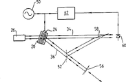
At first referring to Fig. 1, wherein M signal is a surface acoustic wave (SAW).Piezoelectricity SAW substrate 4 is such as quartz or LiNbO
3, being installed on the translate stage 2 of a precision, the latter is by a step motor system operation, and this step motor system can be along the direction shown in the arrow 18 with the little moved further that increases progressively.Produce surface acoustic wave by SAW interdigital sensor 6 in SAW substrate 4, elementary rf wave is provided for sensor 6 from a stable rf source 8 through a flexible cable 10.SAW absorber 12 is positioned at the relative end of SAW substrate 4 and sensor 6, with the sorbent surface sound wave, so that they can not be reflected in substrate 4.Also has a SAW absorber (not shown) in end with the contiguous SAW substrate 4 of sensor 6.One fixedly SAW probe 14 extract the part of surface acoustic wave and convert thereof into a secondary rf electric signal.This secondary rf electric signal and be sent to the phase detectors 16 that obtains setting with the relative phase of measuring two rf electric signal, for example a vector voltage meter from the primary signal in rf source 8.
In operation, translate stage 2 is positioned at a null displacement to be set, and obtains record from the elementary rf electric signal in source 8 with from the relative phase between the secondary rf electric signal of probe 14.When step motor 2 moved, piezoelectricity SAW substrate 4 was moved with respect to static probe 14, thereby had changed the path of the surface acoustic wave from sensor 6 to probe 14.This change in path length has changed the phase place of the surface acoustic wave that is extracted by probe 14, thereby has changed the phase place of the secondary rf electric signal that is sent to phase detectors 16.Therefore, from the elementary rf electric signal in source 8 and relative phase, changed and the directly relevant amount that moves of translate stage 2 from the secondary rf electric signal of probe 14.
The rf electric signal has the frequency of about 1GHz usually, and this will cause the surface acoustic wave of wavelength between 3 and 8 microns in typical SAW substrate 4.Therefore, the change that the measured relative phase of detecting device 16 is 1 ° is corresponding to 1/360 displacement of translate stage 2 of multiply by the wavelength of probe 14 surface acoustic waves that extracted.For example, if the surface acoustic wave that produces in the SAW substrate has the wavelength of 3000nm, then the detected 1 ° relative phase of phase detectors changes the displacement corresponding to about 8nm.If the equipment of Fig. 1 according to the wavelength of surface acoustic wave have about 1 and 4nm between spatial resolution, then the phase detectors of prior art can measuring accuracy at least 0.2 ° relative phase.
Embodiments of the invention shown in Figure 2 have adopted bulk acoustic wave rather than surface acoustic wave as M signal.The equipment of Fig. 2 comprises a laser instrument 26, and it should be a stable light source, and promptly it has big coherent length and constant intensity, and has suitable power, so that the good signal noise ratio to be provided.Can adopt helium-neon laser with about 100 meters coherent length.Laser beam from laser instrument 26 is focused on (though focusing is always unessential) in a sound-light Prague sensor 20 by convex lens 28.The sound wave medium of Prague sensor 20 should have low sound wave loss (this means adopt monocrystalline), stable, can with acceptable cost with big size (a few cm) obtain, optical clear and being preferably in has little under its installment state or serve as zero velocity of sound effective temperature coefficient.This sound wave medium of Prague sensor 20 can be such as quartz, sapphire, GaP, LiNbO
3, MgAl
2O
4Or Al
2O
3This Prague sensor 20 is installed (for example directly installing with bolt) rigidly on a translate stage 22, and translate stage 22 can obtain electric stepping with increasing progressively of sub-micron.A sonic sensor 24 is positioned at an end of Prague sensor 20, and an elementary rf electric signal is sent to sensor 24 from a network analyser 32 through a power amplifier 30.Network analyser 32 can be replaced by the phase detectors 16 of Fig. 1 and stable rf source 6.Sonic sensor 24 causes the rf bulk acoustic wave in Prague sensor 20.
If measuring is to carry out on several centimetres length, promptly required advancing is several centimetres, and then Prague sensor 20 must have several centimetres length, and the sound wave that sensor 24 produces must be advanced several centimetres with the form of collimated beam.Therefore the diameter D of sensor 24 must satisfy: D
2/ l
Acoustic>required travel distance, wherein l
AcousticIt is the wavelength of sound wave.Because l
AcousticTo be 5 microns magnitude, D should have about 1cm in the magnitude of 1mm and sound wave Prague sensor 20
2Cross-sectional area, to avoid the reflection of sound wave from its sidewall.More than supposed medium at the acoustics isotropy.The sensor diameter of 1mm than general institute may adopt greatly, to cause low electrical impedance.Yet to compare be moderate to the electric bandwidth of required sensor 24 with other application of great majority, so that sensor 24 can mate on electricity with for example 50 ohm source under what situation of difficult not having.Can adopt such as the LiNbO that engages
3Sensor.
When laser beam is mapped on Prague sensor 20, produce two light beams 34,36 from this sensor.The driving power of sonic sensor 24 is preferably such, promptly makes about 50% of laser beam be deflected and stays 50% and be not deflected, because this makes the signal that comes out from photodiode 44 reach best.The frequency of light beams deflected 36 is Wo+W, and wherein Wo is that the frequency of laser beam and W are the frequencies from the elementary rf signal of network analyser 32, this light beam 36 scioptics 38 and being mapped on the beam splitter 40.The frequency of undeflected light beam 34 is Wo, and light beam 34 scioptics 38 and mirror 39 and be mapped on the beam splitter 40, and beam splitter 40 can be a cube splitter.The setting of lens 38, mirror 39 and beam splitter 40 has guaranteed that deflection and undeflected light beam 36 and 34 difference are overlapping, and had parallel wavefront and identical polarity when they is focused a 2GHz bandwidth photodiode 44 through lens 42.Photodiode 44 preferably has big as far as possible area, so that can intercept and capture synthesized laser beam 34 and 36, can be as big as 1mm if the latter does not focus on its diameter by the lens such as lens 42.Secondary rf electric signal from photodiode 44 is provided to network analyser 32 through a 3dB attenuator 46 (it forms the direct current return path for photodiode 44) and a prime amplifier 48 subsequently.Network analyser 32 is measured from the elementary rf electric signal of network analyser 32 and relative phase from the secondary rf electric signal of prime amplifier 48.
In operation, translate stage 22 is in null displacement to be set, and obtains record from the elementary rf electric signal of network analyser 32 and from the relative phase between the secondary rf electric signal of prime amplifier 48.When step motor 22 moved, sound-light Prague sensor 20 moved with respect to the laser beam of injecting sensor 20 through lens 28 from laser instrument 26.Detailed sound-light action between laser beam and the rf bulk acoustic wave is a diffraction and the mixing of the complexity of reflection, and here it is not gone through, but laser beam has replaced the solid mechanical probe 14 among Fig. 1 effectively.The phase place that in sensor 20, has comprised the rf bulk acoustic wave through the light beams deflected 36 of scattering.Therefore when step motor 22 carried out displacement, bulk acoustic wave had been changed from the path that sensor 24 is advanced before having an effect with laser beam.Therefore, taken place to move with the phase place of the bulk acoustic wave of laser beam effect, this moves the phase place that makes deflected optical signal 36 and has taken place to move.Secondary rf electric signal from photodiode 44 comprises this phase shifts, so be changed from the elementary rf electric signal of network analyser 32 and from the relative phase between the secondary rf electric signal of prime amplifier 48.Therefore, network analyser 32 measured relative phases have changed a direct relevant amount of the motion with step motor 22.
The rf signal generally has the frequency that is approximately 1GHz, and it will cause the bulk acoustic wave of wavelength between 3 and 8 microns in typical sound-light Prague sensor 20.Therefore 1 ° the relative phase that is measured by network analyser changes, and is 1/360 to multiply by the wavelength with the sound wave of laser beam effect corresponding to the displacement of translate stage 22.For example, if the wavelength of the bulk acoustic wave that causes in Prague sensor 20 is 3000nm, then the relative phase of 1 ° of measuring of network analyser 32 changes the displacement corresponding to 8nm.The phase detectors of prior art can be being at least 0.2 ° precision measure relative phase, this make Fig. 2 equipment according to the wavelength of bulk acoustic wave can have about 1 and 4nm between spatial resolution.
By cancellation lens 38 and 42 and make mirror 39, beam splitter 40 and photodiode 44 approaching with Prague sensor 20 as much as possible, can make the setting of Fig. 2 more stable.The influence that this has reduced the vibration of parts has reduced the influence of the air eddy in light beam 34 and 36 critical areas that separated by the space, and has reduced caused inexactness when the coherent length of laser has identical magnitude with path length difference.Air eddy in that light beam 34 and 36 is separated to locate can be eliminated by adopt a glass in this zone.
In the equipment of Fig. 3 a, M signal is a light signal.Setting shown in Fig. 3 a and shown in Figure 2 similar, just sound-light Prague sensor 20 is fixed and the displacement that will measure has changed the path of deflection light wave 36.The equipment of Fig. 3 a comprises a laser instrument 26, is drawn towards Prague sensor 20 that is fixed from its laser beam.Sensor 20 caused requirements in Prague are lower than being provided with of Fig. 2, because no longer need big sound wave path.Preferably adopt slower sound wave medium, for example TeO
2, because it can provide light beam 34 to separate with 36 big angle with moderate frequency.A sonic sensor 24 is positioned at an end of Prague sensor 20, and is imported in the sensor 24 from the elementary rf electric signal in a stable rf source 50.Similar with being provided with of Fig. 2, sonic sensor 24 causes the rf bulk acoustic wave in Prague sensor 20.So when laser beam is introduced into Prague sensor 20, from this sensor, come out two laser beams 34 and 36.
Deflected beam 34 is not drawn towards beam splitter 58.Deflected beam 36 is drawn towards a mirror 56 through a beam splitter 52.Be drawn towards beam splitter 58 from mirror 56 beam reflected through beam splitter 52.Mirror 56 is installed on translate stage 22 (not shown)s, so that mirror 56 moves along the direction of arrow.The path that moves thereby changed light beam 36 of mirror 56.Being provided with of beam splitter 58 guaranteed that deflection and deflected beam 36 not are overlapping respectively and have parallel wavefront and identical polarity on inciding photodiode 60 time with 34.Secondary rf electric signal from photodiode 60 is provided to a vector voltage meter 62 subsequently, and the latter is to measuring from the secondary signal of photodiode 60 with from the relative phase between the primary signal in rf source 50.In order to improve efficient, can make polarization beam apparatus to beam splitter 52, and use with quarter-wave plate and 1/2nd wave plates by rights, thereby guarantee that the light beam that arrives detecting device has identical polarity.
When making mirror move a displacement d, the path of defection signal 36 has changed 2d, and this has caused a phase change of defection signal 36, and this change with degree when representing is
360 (2d/l
Optical) l wherein
OpticalIt is the wavelength of defection signal 36.If therefore the vector voltage meter measures 1 ° relative phase change, then for the optical wavelength that is generally 500nm, the displacement of the translate stage of Fig. 3 is
(l
Optical/ 2)/360 effect of 1nm Prague sensor 20 is to produce the frequency displacement operation, and can adopts other technology, drives integrated light phase or amplitude modulator or single sideband mixer such as rf.Prague sensor 20 has this advantage as a single sideband mixer really, and the required frequency displacement of interferometer and the apart of the light beam of frequency displacement not are provided naturally.
Fig. 3 b has shown a kind of correction form of Fig. 3 a, and has adopted identical label to come the identical part of indication equipment.The working method of the equipment among Fig. 3 b is identical with Fig. 3 a's, and just deflected beam 34 rather than deflected beam 36 have not obtained phase shift.As a kind of replacement to employing detecting device 16 among Fig. 1, the network analyser 32 of Fig. 2 or the vector voltage meter 62 of Fig. 3 a and 3b have adopted simple double balanced mixer, the latter has the sine output that has phase place substantially for the level of constant secondary rf electric signal and elementary rf electric signal, and described output is zero at 90 ° of phase differential places.Can come the bigness scale amount is carried out in the displacement of translate stage this moment by count cycle (i.e. 360 ° phase change), and carefully measure by the frequency of the rf signal that is input to sensor is regulated to return to zero output (90 ° of phase differential) state subsequently.To recovering 90 ° of frequency shifts that phase differential is required, can measure with very high precision.The advantage of this replacement is to be that the zero output point is operated at a point only, and it is insensitive for the changes in amplitude of primary and secondary rf electric signal.Another kind may be by a local oscillator primary and secondary rf electric signal to be carried out downward mixing, so that phase measurement can be carried out on lower frequency easily.
Two kinds of sound-light actions are arranged, i.e. isotropy effect and anisotropisation.Above description is assumed to isotropic sound-light action.In above-mentioned equipment, the light signal that also can adopt wherein deflection by phase shift anisotropy sound-light action of 90 °, thereby make deflection and undeflected light signal overlapping and have parallel wavefront and identical polarity when they incide on the photodiode as long as 90 ° of phase shifts are compensated.
Claims (30)
1. be used for the equipment of the displacement of Measuring Object, comprise:
A radio frequency (rf) source is used to produce an elementary stable rf electric signal,
A sensing device is used for utilizing at least a part of elementary rf electric signal to produce a M signal, and the wavelength of described M signal is less than the wavelength of elementary rf electric signal,
A phase changer, it when this equipment uses with the M signal effect and interrelate with object by this way, i.e. the displacement of object make phase changer with the path of M signal changed one with the direct relevant amount of this displacement,
A phase place transfer device, be used for utilizing at least in part the M signal after having an effect with phase changer to produce a secondary stable rf electric signal by this way, make that promptly the phase place of this M signal that process acts on is passed to this secondary rf electric signal, and
Phase detectors, the phase place that is used to measure secondary rf electric signal when ohject displacement with respect to the change of elementary rf electric signal.
2. according to the equipment of claim 1, wherein M signal is a light signal.
3. according to the equipment of claim 2, wherein sensing device comprises that an optical signal source that is used to produce light signal and one are used for that this light signal and elementary rf electric signal are carried out mixing and obtain first light signal of frequency displacement and the mixer device of second light signal that does not obtain frequency displacement to produce one, and one in first and second light signals can be this M signal.
4. according to the equipment of claim 3, wherein mixer device is a sound-optical sensor, in this sound-optical sensor, be subjected to the sonic transducer generation body radio frequency sound wave that elementary rf electric signal drives, and light signal is introduced in this sound-optical sensor to produce first light signal and second light signal that does not obtain deflection that obtains deflection by one.
5. according to any one the equipment in the claim 2 to 4, wherein phase changer is a mirror, and M signal is drawn towards this mirror and this mirror is rigidly secured on the object.
6. according to any one the equipment in the claim 3 to 5, wherein the phase place transfer device comprises that one is used for first and second light signals are carried out mixing to produce the device of a difference frequency signal, and this difference frequency signal is secondary rf electric signal.
7. according to the equipment of claim 6, wherein the phase place transfer device comprises that a photodiode and one are used for guiding first and second light signals on this photodiode device by this way, even described signal is overlapping with identical polarity with parallel wavefront.
8. according to the equipment of claim 1, wherein M signal is a rf sound wave.
9. equipment according to Claim 8, wherein sensing device comprises that a sound wave medium and one are driven to produce the sonic transducer of rf sound wave (it is a M signal) in this sound wave medium by elementary rf electric signal, and phase changer when equipment uses with this sound wave effect and relevant with object by this way, promptly make the displacement of object change the path by the sound wave of the sound wave medium between sonic transducer and the sonic probe, this sonic probe has formed at least a portion of phase place transfer device.
10. according to the equipment of claim 9, wherein phase changer comprises sonic transducer and the medium that is rigidly secured on the object, and it is fixing that sonic probe has obtained so that the displacement of object make sonic transducer and medium with respect to sonic probe move one with the direct relevant amount of this displacement.
11. according to the equipment of claim 9 or 10, wherein M signal is a rf bulk acoustic wave.
12. equipment according to claim 11, wherein the sound wave medium is that a sound-optical sensor and sonic transducer obtain being provided with to produce a rf bulk acoustic wave (it is a M signal) in this sound-optical sensor, and the phase place transfer device comprises an optical signal source, this optical signal source produces a light signal (it has constituted sonic probe), this light signal is introduced in the sound-optical sensor and with bulk acoustic wave and has an effect to produce first light signal and second light signal that does not obtain frequency displacement that obtains frequency displacement, this phase place transfer device comprises that further one is used for this first and second light signal is carried out mixing to produce the device of a difference frequency signal, and this difference frequency signal is exactly secondary rf electric signal.
13. according to the equipment of claim 12, wherein be used for to first and second light signals carry out mixing with the device that produces a difference frequency signal comprise a photodiode be used for guiding first and second light signals into photodiode so that described signal with the parallel wavefront device overlapping with identical polarity.
14. according to the equipment of claim 9 or 10, wherein M signal is a radio frequency surface acoustic wave.
15. according to the equipment of claim 14, wherein the sound wave medium is a surface acoustic wave substrate, and sonic transducer obtains being provided with producing a surface acoustic wave (it is a M signal) in this substrate, and the phase place transfer device is a surface acoustic wave probe.
16. equipment according to any one claim of front, frequency tuning can be carried out in the rf source that wherein is used to produce elementary rf electric signal, to make the frequency of elementary rf electric signal can access tuning to recover the relative phase between the primary and secondary rf electric signal before the displacement when the ohject displacement.
17. as above in conjunction with the explanation with Fig. 1 to 3 in any one carry out specifically described equipment.
18. be used for the method for the displacement of Measuring Object, comprise:
Produce an elementary stable radio frequency (rf) electric signal,
Utilize this primary signal to produce a M signal at least in part, the wavelength of described M signal is less than the wavelength of elementary rf electric signal,
Make this M signal and have an effect by this way with a relevant phase changer of object, promptly make the displacement of this object cause this phase changer the path of M signal change one with the direct relevant amount of this displacement,
Make this object produce a displacement,
Utilize at least in part with phase changer and have an effect M signal afterwards and produce a secondary stable rf electric signal by this way, promptly make the phase place of this M signal be passed to this secondary rf electric signal, and
The phase place of measurement this secondary rf electric signal when ohject displacement is with respect to the change of elementary rf electric signal.
19. according to the method for claim 18, wherein M signal is a light signal.
20. method according to claim 19, wherein the generation of M signal comprise produce a light signal and with this light signal and the mixing of elementary rf electric signal to produce first light signal and second light signal that does not obtain frequency displacement that obtains frequency displacement, one in these two signals can be M signal.
21. according to the method for claim 20, wherein the mixing of light signal and elementary rf electric signal is included in and utilizes a sonic transducer that is driven by elementary rf electric signal to produce body radio frequency sound wave and light signal is incorporated into first light signal and undeflected second light signal to produce a deflection in the sound-optical sensor in the sound-optical sensor.
22. according to the method for claim 20 or 21, the generation of wherein secondary rf electric signal comprises that with the first and second light signal mixing to produce a difference frequency signal, this difference frequency signal is secondary rf electric signal.
23. according to the method for claim 22, the generation of wherein secondary rf electric signal comprise guide first and second light signals into photodiode so that described light signal with parallel wavefront and identical polarity overlaid.
24. according to the method for claim 18, wherein M signal is the radio frequency acoustic signals.
25. method according to claim 24, wherein the generation of M signal comprises that utilization produces an acoustic signals (M signal) by the sonic transducer that elementary rf electric signal drives, and the generation of secondary rf electric signal comprises this acoustic signals and a sonic probe are had an effect.
26. according to the method for claim 25, wherein the displacement of object make sonic transducer with respect to sonic probe move one with the direct relevant amount of this displacement.
27. according to any one the method in the claim 24 to 26, wherein M signal is a RF bulk acoustic wave.
28. according to any one the method in the claim 24 to 26, wherein M signal is a radio frequency surface acoustic wave.
29., when wherein the measurement of the phase change of secondary rf electric signal being included in ohject displacement elementary rf electric signal is carried out frequency tuning to recover the relative phase of primary and secondary rf electric signal before displacement according to any one the method in the claim 18 to 28.
30. it is as above in conjunction with any one the described method among explanation and Fig. 1 to 3.
Applications Claiming Priority (2)
| Application Number | Priority Date | Filing Date | Title |
|---|---|---|---|
| GB9300556.9 | 1993-01-13 | ||
| GB939300556A GB9300556D0 (en) | 1993-01-13 | 1993-01-13 | Nanmeter metrology |
Publications (1)
| Publication Number | Publication Date |
|---|---|
| CN1102288A true CN1102288A (en) | 1995-05-03 |
Family
ID=10728633
Family Applications (1)
| Application Number | Title | Priority Date | Filing Date |
|---|---|---|---|
| CN94190054A Pending CN1102288A (en) | 1993-01-13 | 1994-01-10 | Nanometer metrology |
Country Status (7)
| Country | Link |
|---|---|
| EP (1) | EP0630467A1 (en) |
| JP (1) | JPH07504755A (en) |
| KR (1) | KR950700531A (en) |
| CN (1) | CN1102288A (en) |
| GB (2) | GB9300556D0 (en) |
| TW (1) | TW251347B (en) |
| WO (1) | WO1994016294A1 (en) |
Family Cites Families (2)
| Publication number | Priority date | Publication date | Assignee | Title |
|---|---|---|---|---|
| DE1006166B (en) * | 1956-04-06 | 1957-04-11 | Erich Hoffmann Werkstaetten Fu | Method for measuring distances by means of sound waves, in particular ultrasonic waves and apparatus for practicing the method |
| GB1410152A (en) * | 1973-03-28 | 1975-10-15 | Plessey Co Ltd | Linear measuring device |
-
1993
- 1993-01-13 GB GB939300556A patent/GB9300556D0/en active Pending
-
1994
- 1994-01-10 CN CN94190054A patent/CN1102288A/en active Pending
- 1994-01-10 EP EP94903970A patent/EP0630467A1/en not_active Ceased
- 1994-01-10 JP JP6515820A patent/JPH07504755A/en active Pending
- 1994-01-10 GB GB9417796A patent/GB2280030B/en not_active Expired - Fee Related
- 1994-01-10 WO PCT/GB1994/000039 patent/WO1994016294A1/en not_active Application Discontinuation
- 1994-02-08 TW TW083101075A patent/TW251347B/zh active
- 1994-09-13 KR KR1019940703192A patent/KR950700531A/en not_active Application Discontinuation
Also Published As
| Publication number | Publication date |
|---|---|
| JPH07504755A (en) | 1995-05-25 |
| GB2280030B (en) | 1996-08-28 |
| EP0630467A1 (en) | 1994-12-28 |
| GB2280030A (en) | 1995-01-18 |
| GB9300556D0 (en) | 1993-03-03 |
| TW251347B (en) | 1995-07-11 |
| KR950700531A (en) | 1995-01-16 |
| WO1994016294A1 (en) | 1994-07-21 |
| GB9417796D0 (en) | 1994-10-26 |
Similar Documents
| Publication | Publication Date | Title |
|---|---|---|
| US8670128B2 (en) | Profile measuring apparatus | |
| US6445453B1 (en) | Scanning interferometric near-field confocal microscopy | |
| CN102944176B (en) | Displacement measuring system of heterodyne grating interferometer | |
| CN106289068B (en) | A kind of two degrees of freedom heterodyne grating interferometer displacement measurement method | |
| US20060256350A1 (en) | Laser scanning interferometric surface metrology | |
| CN105823422A (en) | Two-degree-of-freedom heterodyne grating interferometer displacement measurement system and method | |
| CN102288103B (en) | Folding-fabry-perot-cavity-based cavity length measurement method and device | |
| CN1844868A (en) | Method and apparatus for measuring laser wavelength by heterodyne interference method | |
| Lawrence et al. | MEMS characterization using laser Doppler vibrometry | |
| Ngoi et al. | Two-axis-scanning laser Doppler vibrometer for microstructure | |
| Jungerman et al. | Phase sensitive scanning optical microscope | |
| JPH04369418A (en) | Cantilever type probe and interatomic force microscope, data processing apparatus | |
| CN1280293A (en) | Method for measuring nanometer precision of object displacement | |
| CN1102288A (en) | Nanometer metrology | |
| CN105716523B (en) | A kind of high-precision, high-speed motion measuring system being suitable for large format motion planning | |
| CN111656183B (en) | Apparatus and method for determining the position of a target structure on a substrate | |
| US20090002716A1 (en) | Laser scanning interferometric surface metrology | |
| Hesjedal | Surface acoustic wave-assisted scanning probe microscopy—a summary | |
| KR101085061B1 (en) | Viration-insensitive interferometer using high-speed camera and continuous phase-scanning method | |
| Ngoi et al. | An acousto-optic vibrometer for measurement of vibration in ultra-precision machine tools | |
| US7173714B2 (en) | Apparatus for parallel detection of the behaviour of mechanical micro-oscillators | |
| CN1598482A (en) | Satellite light communication high speed tracking detector and its detecting method | |
| KR101171362B1 (en) | Heterodyne laser interferometer improved in phase detecting means | |
| Oshio et al. | Atomic force microscope using an optical fiber heterodyne interferometer free from external disturbances | |
| EP0390166B1 (en) | Edge detector |
Legal Events
| Date | Code | Title | Description |
|---|---|---|---|
| C06 | Publication | ||
| PB01 | Publication | ||
| C10 | Entry into substantive examination | ||
| SE01 | Entry into force of request for substantive examination |