CN110142811B - Green Chinese onion cutter - Google Patents
Green Chinese onion cutter Download PDFInfo
- Publication number
- CN110142811B CN110142811B CN201910450476.8A CN201910450476A CN110142811B CN 110142811 B CN110142811 B CN 110142811B CN 201910450476 A CN201910450476 A CN 201910450476A CN 110142811 B CN110142811 B CN 110142811B
- Authority
- CN
- China
- Prior art keywords
- hollow
- nut
- spring
- sliding
- cam
- Prior art date
- Legal status (The legal status is an assumption and is not a legal conclusion. Google has not performed a legal analysis and makes no representation as to the accuracy of the status listed.)
- Active
Links
Images


Classifications
-
- B—PERFORMING OPERATIONS; TRANSPORTING
- B26—HAND CUTTING TOOLS; CUTTING; SEVERING
- B26D—CUTTING; DETAILS COMMON TO MACHINES FOR PERFORATING, PUNCHING, CUTTING-OUT, STAMPING-OUT OR SEVERING
- B26D1/00—Cutting through work characterised by the nature or movement of the cutting member or particular materials not otherwise provided for; Apparatus or machines therefor; Cutting members therefor
- B26D1/01—Cutting through work characterised by the nature or movement of the cutting member or particular materials not otherwise provided for; Apparatus or machines therefor; Cutting members therefor involving a cutting member which does not travel with the work
- B26D1/12—Cutting through work characterised by the nature or movement of the cutting member or particular materials not otherwise provided for; Apparatus or machines therefor; Cutting members therefor involving a cutting member which does not travel with the work having a cutting member moving about an axis
-
- B—PERFORMING OPERATIONS; TRANSPORTING
- B26—HAND CUTTING TOOLS; CUTTING; SEVERING
- B26D—CUTTING; DETAILS COMMON TO MACHINES FOR PERFORATING, PUNCHING, CUTTING-OUT, STAMPING-OUT OR SEVERING
- B26D7/00—Details of apparatus for cutting, cutting-out, stamping-out, punching, perforating, or severing by means other than cutting
- B26D7/06—Arrangements for feeding or delivering work of other than sheet, web, or filamentary form
-
- B—PERFORMING OPERATIONS; TRANSPORTING
- B26—HAND CUTTING TOOLS; CUTTING; SEVERING
- B26D—CUTTING; DETAILS COMMON TO MACHINES FOR PERFORATING, PUNCHING, CUTTING-OUT, STAMPING-OUT OR SEVERING
- B26D7/00—Details of apparatus for cutting, cutting-out, stamping-out, punching, perforating, or severing by means other than cutting
- B26D7/26—Means for mounting or adjusting the cutting member; Means for adjusting the stroke of the cutting member
- B26D7/2614—Means for mounting the cutting member
-
- B—PERFORMING OPERATIONS; TRANSPORTING
- B26—HAND CUTTING TOOLS; CUTTING; SEVERING
- B26D—CUTTING; DETAILS COMMON TO MACHINES FOR PERFORATING, PUNCHING, CUTTING-OUT, STAMPING-OUT OR SEVERING
- B26D2210/00—Machines or methods used for cutting special materials
- B26D2210/02—Machines or methods used for cutting special materials for cutting food products, e.g. food slicers
Abstract
The invention relates to a cutter, in particular to a green Chinese onion cutter. The technical problem to be solved is as follows: provides a green Chinese onion cutter which does not irritate eyes of people, has higher safety and cuts more uniformly. The technical scheme of the invention is as follows: a scallion cutter comprises a first bracket, a hollow pipe, a second bracket, a first bearing, a first rotating shaft, a first rotating disc, a first belt wheel and the like; the first support is provided with a hollow pipe, the upper part of the left side of the hollow pipe is provided with a second support, the lower part of the right side of the second support is provided with a first bearing in an embedded mode, and the first bearing is provided with a first rotating shaft. The hollow tube can be used for cutting without direct contact of people with the scallion, and people are far away from the scallion, so that the discomfort of hot eyes, tearing of eyes and the like can not be caused; the cutting device is arranged, so that people can cut without directly contacting the cutter, people do not contact the cutter, the phenomenon that the cutter cuts hands is avoided, and the safety is higher.
Description
Technical Field
The invention relates to a cutter, in particular to a green Chinese onion cutter.
Background
The green Chinese onions are popular with people due to special taste, people often use the green Chinese onions to make dumplings or steamed stuffed buns, when preparing the green Chinese onions stuffing, people need to cut the green Chinese onions firstly, then add seasonings to prepare the stuffing, when people cut the green Chinese onions, the green Chinese onions are usually placed on a chopping board and then manually cut by using a cutter, people are close to the chopping board, and the green Chinese onions can stimulate eyes of people when cutting the green Chinese onions, so that people can tear, and people can feel uncomfortable; meanwhile, when the cutter is used for cutting, the cutter is close to the hand of a user, so that the hand of the user can be easily cut, and the user can be injured; the manual cutting of green Chinese onions is not uniform enough, and people are required to chop the green Chinese onions, so that the manual cutting cannot be finished at one time.
Disclosure of Invention
In order to overcome the defects that when people cut the scallion, the eyes of people are easy to be stimulated, people are easy to be injured and the cutting is not uniform enough, the technical problem to be solved is as follows: provides a green Chinese onion cutter which does not irritate eyes of people, has higher safety and cuts more uniformly.
The technical scheme of the invention is as follows: a green Chinese onion cutter comprises a first support, a hollow pipe, a second support, a first bearing, a first rotating shaft, a first rotating disc, a first belt wheel, a cutting device, a second bearing, a hollow rotating shaft, a fixed screw, a second belt wheel, a belt, a hollow sleeve, an arc slide rail, an arc slide block, a second nut, a second screw and a handle, wherein the hollow pipe is arranged on the first support, the second support is arranged at the upper part of the left side of the hollow pipe, the first bearing is embedded at the lower part of the right side of the second support, the first rotating shaft is arranged on the first bearing, the first rotating disc is arranged at the lower part of the first rotating shaft, the cutting device is arranged at each of the left and right sides of the first rotating disc, the first belt wheel is arranged at the lower end of the first rotating disc, the second bearing is embedded at the left side of the second support, the hollow rotating shaft is arranged on the second bearing, a threaded hole is, fixing screw is located the second bearing top, hollow shaft lower extreme is equipped with the second band pulley, around there being the belt on second band pulley and the first band pulley, upper portion is equipped with hollow cover in the hollow shaft, be equipped with the arc slide rail in the hollow cover, the fixing screw left end passes hollow cover and arc slide rail, the equal slidingtype of arc slide rail left and right sides is equipped with the arc slider, fixing screw is located the top of arc slider, it is equipped with the second nut to control between the two sides arc slider, second nut right side and fixing screw left end contact, there is the second screw rod through threaded connection in the second nut, the second screw rod upper end is equipped with the handle, the handle is located second support top.
In one embodiment, the cutting device comprises a blade, a fixed block, a first screw rod and a first nut, grooves are formed in the left side and the right side of a first rotary disc, the blade is placed in the grooves, the left blade is positioned above the right blade, first through holes are formed in the left side and the right side of the right blade, sliding holes are formed in the left lower portion and the right upper portion of the first rotary disc, the sliding holes are communicated with the grooves, the fixed block is movably arranged in the sliding holes, second through holes are formed in the left side and the right side of the left upper portion and the right lower portion of the first rotary disc, the second through holes are positioned above the first through holes and are communicated with the grooves, the first screw rods are arranged on the left side and the right side of the top of the left fixed block and the bottom of the right fixed block, the upper end of the left first screw rod penetrates through holes and the second through holes in the left direction, the lower end of the right first, first screw rod is last to have first nut through threaded connection, and the first nut in the left is located first carousel upside, and the right-hand first nut is located first carousel downside.
In one embodiment, the cutting device further comprises a first cam, a first baffle and a first spring, the first cam is arranged at the lower part of the first rotating shaft and located between the first rotating disc and the first belt wheel, a first guide hole is formed in the lower part of the left side of the hollow tube, the first baffle is movably arranged in the first guide hole and located below the right cutting device, the left end of the first baffle is in contact with the right side of the first cam, the first spring is wound on the left side of the first baffle, and the right end of the first spring is connected with the left side of the hollow tube.
In one embodiment, the nut further comprises a second rotary disc, a sliding sleeve, a clamping rod, a second baffle and a second spring, the second rotary disc is arranged on the upper portion of the outer side of the second nut, a plurality of clamping grooves are uniformly formed in the outer side of the second rotary disc, the sliding sleeve is arranged on the left side of the top of the hollow rotary shaft and located on the left side of the second rotary disc, the clamping rod is arranged in the sliding sleeve in a sliding mode, the second baffle is arranged on the right side of the clamping rod, the second spring is connected to the left side of the second baffle, the left end of the second spring is connected with the right side of the sliding sleeve, the right end of the clamping rod.
In one embodiment, the cutting device further comprises a second cam, a gear, a first rack, a second rack, a guide pipe, a third spring, a slide rod and a roller, wherein the second cam is arranged on the first rotating shaft and is positioned above the first rotating disc, the front side of the hollow pipe is rotatably provided with the gear, second guide holes are symmetrically formed in the left wall and the right wall of the hollow pipe, the second guide holes are positioned above the right cutting device, the guide pipe is movably arranged in the second guide holes, the upper part of the front side of the left guide pipe is provided with the first rack which is positioned on the upper side of the gear, the first rack is meshed with the gear, the upper part of the front side of the right guide pipe is provided with the second rack which is positioned on the lower side of the gear, the second rack is meshed with the gear, the guide pipe is internally connected with the third spring, the right end of the left third spring is symmetrically provided with the slide rod with the left end of, the right side of the right sliding rod is positioned in the right guide pipe, the left side of the first rack is provided with a roller, the roller is positioned on the right side of the second cam, and the roller is in contact with the second cam.
The hollow tube can be used for cutting without direct contact of people with the scallion, and people are far away from the scallion, so that the discomfort of hot eyes, tearing of eyes and the like can not be caused; the cutting device can cut without people directly contacting with the cutter, and people do not contact with the cutter, so that the phenomenon that the cutter cuts hands is avoided, and the safety is higher; can prevent through the first baffle and the slide bar that set up that the scallion once only descends too much, and lead to the not enough even of scallion cutting, can cut the scallion more evenly, need not carry out secondary treatment.
Drawings
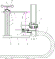
Fig. 1 is a schematic front view of the present invention.
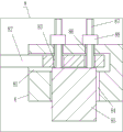
Fig. 2 is an enlarged front view structural diagram of the cutting device of the present invention.
Fig. 3 is an enlarged front view structural diagram of the present invention a.
Fig. 4 is a partial top enlarged front view structure diagram of the present invention.
Fig. 5 is an enlarged front view structural diagram of the present invention B.
Fig. 6 is a schematic top view of the second cam of the present invention.
Labeled as: 1. the gear comprises a first support, 2, a hollow pipe, 3, a second support, 4, a first bearing, 5, a first rotating shaft, 6, a first rotating disc, 7, a first belt wheel, 8, a cutting device, 81, a groove, 82, a blade, 83, a first through hole, 84, a sliding hole, 85, a fixing block, 86, a second through hole, 87, a first screw rod, 88, a first nut, 9, a second bearing, 10, a hollow rotating shaft, 101, a threaded hole, 102, a fixing screw rod, 11, a second belt wheel, 12, a belt, 13, a hollow sleeve, 14, an arc-shaped sliding rail, 15, an arc-shaped sliding block, 16, a second nut, 17, a second screw rod, 18, a handle, 19, a first cam, 20, a first guide hole, 21, a first baffle, 22, a first spring, 23, a second rotating disc, 24, a clamping groove, 25, a sliding sleeve, 26, a clamping rod, 27, a second baffle, 28, a second spring, 29, a second cam, 30, a gear, 31. the gear rack mechanism comprises a first rack, a second guide hole, a guide pipe, a third spring, a sliding rod and a roller, wherein the first rack is 32, the second rack is 33, the second guide hole is 34, the guide pipe is 35, the third spring is 36, the sliding rod is 37.
Detailed Description
The technical solutions in the embodiments of the present invention will be clearly and completely described below with reference to the drawings in the embodiments of the present invention, and it is obvious that the described embodiments are only a part of the embodiments of the present invention, and not all of the embodiments. All other embodiments, which can be derived by a person skilled in the art from the embodiments given herein without making any creative effort, shall fall within the protection scope of the present invention.
Example 1
A green Chinese onion cutter is shown in figures 1-3 and comprises a first support 1, a hollow pipe 2, a second support 3, a first bearing 4, a first rotating shaft 5, a first rotating disc 6, a first belt wheel 7, a cutting device 8, a second bearing 9, a hollow rotating shaft 10, a fixed screw 102, a second belt wheel 11, a belt 12, a hollow sleeve 13, an arc-shaped slide rail 14, an arc-shaped slide block 15, a second nut 16, a second screw 17 and a handle 18, wherein the first support 1 is provided with the hollow pipe 2, the first support 1 is connected with the hollow pipe 2 in a welding connection mode, the upper part of the left side of the hollow pipe 2 is provided with the second support 3, the lower part of the right side of the second support 3 is embedded with the first bearing 4, the first rotating shaft 5 is arranged on the first bearing 4, the lower part of the first rotating shaft 5 is provided with the first rotating disc 6, the cutting device 8 is arranged on the left side of the first rotating disc 6, the cutting device, a first belt wheel 7 is arranged at the lower end of a first rotary disc 6, the first rotary disc 6 is connected with the first belt wheel 7 in a welding connection mode, a second bearing 9 is embedded in the left side of a second support 3, a hollow rotary shaft 10 is installed on the second bearing 9, a threaded hole 101 is formed in the upper portion of the right side of the hollow rotary shaft 10, a fixing screw 102 is connected in the threaded hole 101 through threads, the fixing screw 102 is located above the second bearing 9, a second belt wheel 11 is arranged at the lower end of the hollow rotary shaft 10, a belt 12 is wound on the second belt wheel 11 and the first belt wheel 7, a hollow sleeve 13 is arranged at the upper portion in the hollow rotary shaft 10, an arc-shaped slide rail 14 is arranged in the hollow sleeve 13, the left end of the fixing screw 102 penetrates through the hollow sleeve 13 and the arc-shaped slide rail 14, arc-shaped slide blocks 15 are arranged on the left side and the right, arc slider 15 is connected with second nut 16 through welded connection's mode, and the contact of second nut 16 right side and clamping screw 102 left end has second screw rod 17 through threaded connection in the second nut 16, and second screw rod 17 upper end is equipped with handle 18, and handle 18 is located second support 3 top.
Example 2
A green Chinese onion cutter is shown in figures 1-3 and comprises a first support 1, a hollow tube 2, a second support 3, a first bearing 4, a first rotating shaft 5, a first rotating disc 6, a first belt wheel 7, a cutting device 8, a second bearing 9, a hollow rotating shaft 10, a fixed screw 102, a second belt wheel 11, a belt 12, a hollow sleeve 13, an arc slide rail 14, an arc slide block 15, a second nut 16, a second screw 17 and a handle 18, wherein the hollow tube 2 is arranged on the first support 1, the second support 3 is arranged at the upper part of the left side of the hollow tube 2, the first bearing 4 is embedded at the lower part of the right side of the second support 3, the first rotating shaft 5 is arranged on the first bearing 4, the first rotating disc 6 is arranged at the lower part of the first rotating shaft 5, the cutting device 8 is arranged at both sides of the first rotating disc 6, the cutting device 8 is positioned at the left of the hollow tube 2, the first belt wheel 7 is arranged at the lower end of the first rotating disc 6, install hollow pivot 10 on the second bearing 9, open on hollow pivot 10 right side upper portion has screw hole 101, there is fixing screw 102 through threaded connection in the screw hole 101, fixing screw 102 is located second bearing 9 top, hollow pivot 10 lower extreme is equipped with second band pulley 11, around having belt 12 on second band pulley 11 and the first band pulley 7, upper portion is equipped with hollow cover 13 in hollow pivot 10, be equipped with arc slide rail 14 in the hollow cover 13, fixing screw 102 left end passes hollow cover 13 and arc slide rail 14, arc slide rail 14 left and right sides all slidingtype is equipped with arc slider 15, fixing screw 102 is located the top of arc slider 15, be equipped with second nut 16 between the left and right sides arc slider 15, second nut 16 right side and fixing screw 102 left end contact, there is second screw 17 through threaded connection in the second nut 16, second screw 17 upper end is equipped with handle 18, handle 18 is located second support 3 top.
The cutting device 8 comprises a blade 82, a fixed block 85, a first screw 87 and a first nut 88, grooves 81 are respectively formed in the left side and the right side of the first rotary disc 6, the blade 82 is placed in the grooves 81, the left blade 82 is positioned above the right blade 82, first through holes 83 are respectively formed in the left side and the right side of the right portion of the left blade 82 and the left side of the right blade 82, sliding holes 84 are respectively formed in the left lower portion and the right upper portion of the first rotary disc 6, the sliding holes 84 are communicated with the grooves 81, the fixed block 85 is movably arranged in the sliding holes 84, second through holes 86 are respectively formed in the left side upper portion and the right lower portion of the first rotary disc 6, the second through holes 86 are positioned above the first through holes 83, the second through holes 86 are communicated with the grooves 81, the first screw 87 is respectively arranged on the left side and the left side of the top of the left fixed block 85 and the left side of the right fixed block 85, the fixed block 85 is connected with the first screw 87 in a welding mode, the upper, the lower end of the right first screw 87 passes through the right first through hole 83 and the right second through hole 86, the first screw 87 is connected with a first nut 88 through threads, the left first nut 88 is positioned on the upper side of the first rotary disk 6, and the right first nut 88 is positioned on the lower side of the first rotary disk 6.
Example 3
A green Chinese onion cutter is shown in figures 1-3 and comprises a first support 1, a hollow tube 2, a second support 3, a first bearing 4, a first rotating shaft 5, a first rotating disc 6, a first belt wheel 7, a cutting device 8, a second bearing 9, a hollow rotating shaft 10, a fixed screw 102, a second belt wheel 11, a belt 12, a hollow sleeve 13, an arc slide rail 14, an arc slide block 15, a second nut 16, a second screw 17 and a handle 18, wherein the hollow tube 2 is arranged on the first support 1, the second support 3 is arranged at the upper part of the left side of the hollow tube 2, the first bearing 4 is embedded at the lower part of the right side of the second support 3, the first rotating shaft 5 is arranged on the first bearing 4, the first rotating disc 6 is arranged at the lower part of the first rotating shaft 5, the cutting device 8 is arranged at both sides of the first rotating disc 6, the cutting device 8 is positioned at the left of the hollow tube 2, the first belt wheel 7 is arranged at the lower end of the first rotating disc 6, install hollow pivot 10 on the second bearing 9, open on hollow pivot 10 right side upper portion has screw hole 101, there is fixing screw 102 through threaded connection in the screw hole 101, fixing screw 102 is located second bearing 9 top, hollow pivot 10 lower extreme is equipped with second band pulley 11, around having belt 12 on second band pulley 11 and the first band pulley 7, upper portion is equipped with hollow cover 13 in hollow pivot 10, be equipped with arc slide rail 14 in the hollow cover 13, fixing screw 102 left end passes hollow cover 13 and arc slide rail 14, arc slide rail 14 left and right sides all slidingtype is equipped with arc slider 15, fixing screw 102 is located the top of arc slider 15, be equipped with second nut 16 between the left and right sides arc slider 15, second nut 16 right side and fixing screw 102 left end contact, there is second screw 17 through threaded connection in the second nut 16, second screw 17 upper end is equipped with handle 18, handle 18 is located second support 3 top.
The cutting device 8 comprises a blade 82, a fixed block 85, a first screw 87 and a first nut 88, grooves 81 are respectively formed in the left side and the right side of the first rotary disc 6, the blade 82 is placed in the grooves 81, the left blade 82 is positioned above the right blade 82, first through holes 83 are respectively formed in the left side and the right side of the right part of the left blade 82 and the left side of the right blade 82, sliding holes 84 are respectively formed in the left lower part and the right upper part of the first rotary disc 6, the sliding holes 84 are communicated with the grooves 81, the fixed block 85 is movably arranged in the sliding holes 84, second through holes 86 are respectively formed in the left side upper part and the right lower part of the first rotary disc 6, the second through holes 86 are positioned above the first through holes 83, the second through holes 86 are communicated with the grooves 81, the first screw 87 is respectively arranged on the left side and the left side of the top of the left fixed block 85 and the left side of the right fixed block 85, the upper end of, the lower end of the right first screw 87 passes through the right first through hole 83 and the right second through hole 86, the first screw 87 is connected with a first nut 88 through threads, the left first nut 88 is positioned on the upper side of the first rotary disk 6, and the right first nut 88 is positioned on the lower side of the first rotary disk 6.
Still including first cam 19, first baffle 21 and first spring 22, 5 lower parts of first pivot are equipped with first cam 19, first cam 19 is located between first carousel 6 and the first band pulley 7, 2 left side lower parts of hollow tube are opened there is first guiding hole 20, the mobile mode is equipped with first baffle 21 in first guiding hole 20, first baffle 21 is located right-hand cutting device 8 below, 21 left end of first baffle and the contact of first cam 19 right side, 21 left sides of first baffle are around having first spring 22, first spring 22 right-hand member is connected with 2 left sides of hollow tube, first spring 22 passes through welded connection's mode and is connected with hollow tube 2.
Example 4
A green Chinese onion cutter is shown in figures 1-4 and comprises a first support 1, a hollow tube 2, a second support 3, a first bearing 4, a first rotating shaft 5, a first rotating disc 6, a first belt wheel 7, a cutting device 8, a second bearing 9, a hollow rotating shaft 10, a fixed screw 102, a second belt wheel 11, a belt 12, a hollow sleeve 13, an arc slide rail 14, an arc slide block 15, a second nut 16, a second screw 17 and a handle 18, wherein the hollow tube 2 is arranged on the first support 1, the second support 3 is arranged at the upper part of the left side of the hollow tube 2, the first bearing 4 is embedded at the lower part of the right side of the second support 3, the first rotating shaft 5 is arranged on the first bearing 4, the first rotating disc 6 is arranged at the lower part of the first rotating shaft 5, the cutting device 8 is arranged at both sides of the first rotating disc 6, the cutting device 8 is positioned at the left of the hollow tube 2, the first belt wheel 7 is arranged at the lower end of the first rotating disc 6, install hollow pivot 10 on the second bearing 9, open on hollow pivot 10 right side upper portion has screw hole 101, there is fixing screw 102 through threaded connection in the screw hole 101, fixing screw 102 is located second bearing 9 top, hollow pivot 10 lower extreme is equipped with second band pulley 11, around having belt 12 on second band pulley 11 and the first band pulley 7, upper portion is equipped with hollow cover 13 in hollow pivot 10, be equipped with arc slide rail 14 in the hollow cover 13, fixing screw 102 left end passes hollow cover 13 and arc slide rail 14, arc slide rail 14 left and right sides all slidingtype is equipped with arc slider 15, fixing screw 102 is located the top of arc slider 15, be equipped with second nut 16 between the left and right sides arc slider 15, second nut 16 right side and fixing screw 102 left end contact, there is second screw 17 through threaded connection in the second nut 16, second screw 17 upper end is equipped with handle 18, handle 18 is located second support 3 top.
The cutting device 8 comprises a blade 82, a fixed block 85, a first screw 87 and a first nut 88, grooves 81 are respectively formed in the left side and the right side of the first rotary disc 6, the blade 82 is placed in the grooves 81, the left blade 82 is positioned above the right blade 82, first through holes 83 are respectively formed in the left side and the right side of the right part of the left blade 82 and the left side of the right blade 82, sliding holes 84 are respectively formed in the left lower part and the right upper part of the first rotary disc 6, the sliding holes 84 are communicated with the grooves 81, the fixed block 85 is movably arranged in the sliding holes 84, second through holes 86 are respectively formed in the left side upper part and the right lower part of the first rotary disc 6, the second through holes 86 are positioned above the first through holes 83, the second through holes 86 are communicated with the grooves 81, the first screw 87 is respectively arranged on the left side and the left side of the top of the left fixed block 85 and the left side of the right fixed block 85, the upper end of, the lower end of the right first screw 87 passes through the right first through hole 83 and the right second through hole 86, the first screw 87 is connected with a first nut 88 through threads, the left first nut 88 is positioned on the upper side of the first rotary disk 6, and the right first nut 88 is positioned on the lower side of the first rotary disk 6.
Still including first cam 19, first baffle 21 and first spring 22, 5 lower parts of first pivot are equipped with first cam 19, first cam 19 is located between first carousel 6 and the first band pulley 7, 2 left side lower parts of hollow tube are opened there is first guiding hole 20, the mobile mode is equipped with first baffle 21 in first guiding hole 20, first baffle 21 is located right-hand cutting device 8 below, the contact on first baffle 21 left end and first cam 19 right side, first baffle 21 left side is around having first spring 22, first spring 22 right-hand member is connected with 2 left sides of hollow tube.
Still including second carousel 23, the sliding sleeve 25, kelly 26, second baffle 27 and second spring 28, second nut 16 outside upper portion is equipped with second carousel 23, second nut 16 is connected with second carousel 23 through welded connection's mode, second carousel 23 outside evenly opens has a plurality of draw-in grooves 24, hollow pivot 10 top left side is equipped with sliding sleeve 25, sliding sleeve 25 is located the left of second carousel 23, the sliding sleeve 25 internal sliding formula is equipped with kelly 26, kelly 26 right side is equipped with second baffle 27, kelly 26 is connected with second baffle 27 through welded connection's mode, second baffle 27 left side is connected with second spring 28, second spring 28 left end is connected with sliding sleeve 25 right side, second spring 28 is connected with sliding sleeve 25 through welded connection's mode, kelly 26 right-hand member passes second spring 28, kelly 26 right-hand member is located draw-in groove 24.
Example 5
A green Chinese onion cutter is shown in figures 1-6 and comprises a first support 1, a hollow tube 2, a second support 3, a first bearing 4, a first rotating shaft 5, a first rotating disc 6, a first belt wheel 7, a cutting device 8, a second bearing 9, a hollow rotating shaft 10, a fixed screw 102, a second belt wheel 11, a belt 12, a hollow sleeve 13, an arc slide rail 14, an arc slide block 15, a second nut 16, a second screw 17 and a handle 18, wherein the hollow tube 2 is arranged on the first support 1, the second support 3 is arranged at the upper part of the left side of the hollow tube 2, the first bearing 4 is embedded at the lower part of the right side of the second support 3, the first rotating shaft 5 is arranged on the first bearing 4, the first rotating disc 6 is arranged at the lower part of the first rotating shaft 5, the cutting device 8 is arranged at both sides of the first rotating disc 6, the cutting device 8 is positioned at the left of the hollow tube 2, the first belt wheel 7 is arranged at the lower end of the first rotating disc 6, install hollow pivot 10 on the second bearing 9, open on hollow pivot 10 right side upper portion has screw hole 101, there is fixing screw 102 through threaded connection in the screw hole 101, fixing screw 102 is located second bearing 9 top, hollow pivot 10 lower extreme is equipped with second band pulley 11, around having belt 12 on second band pulley 11 and the first band pulley 7, upper portion is equipped with hollow cover 13 in hollow pivot 10, be equipped with arc slide rail 14 in the hollow cover 13, fixing screw 102 left end passes hollow cover 13 and arc slide rail 14, arc slide rail 14 left and right sides all slidingtype is equipped with arc slider 15, fixing screw 102 is located the top of arc slider 15, be equipped with second nut 16 between the left and right sides arc slider 15, second nut 16 right side and fixing screw 102 left end contact, there is second screw 17 through threaded connection in the second nut 16, second screw 17 upper end is equipped with handle 18, handle 18 is located second support 3 top.
The cutting device 8 comprises a blade 82, a fixed block 85, a first screw 87 and a first nut 88, grooves 81 are respectively formed in the left side and the right side of the first rotary disc 6, the blade 82 is placed in the grooves 81, the left blade 82 is positioned above the right blade 82, first through holes 83 are respectively formed in the left side and the right side of the right part of the left blade 82 and the left side of the right blade 82, sliding holes 84 are respectively formed in the left lower part and the right upper part of the first rotary disc 6, the sliding holes 84 are communicated with the grooves 81, the fixed block 85 is movably arranged in the sliding holes 84, second through holes 86 are respectively formed in the left side upper part and the right lower part of the first rotary disc 6, the second through holes 86 are positioned above the first through holes 83, the second through holes 86 are communicated with the grooves 81, the first screw 87 is respectively arranged on the left side and the left side of the top of the left fixed block 85 and the left side of the right fixed block 85, the upper end of, the lower end of the right first screw 87 passes through the right first through hole 83 and the right second through hole 86, the first screw 87 is connected with a first nut 88 through threads, the left first nut 88 is positioned on the upper side of the first rotary disk 6, and the right first nut 88 is positioned on the lower side of the first rotary disk 6.
Still including first cam 19, first baffle 21 and first spring 22, 5 lower parts of first pivot are equipped with first cam 19, first cam 19 is located between first carousel 6 and the first band pulley 7, 2 left side lower parts of hollow tube are opened there is first guiding hole 20, the mobile mode is equipped with first baffle 21 in first guiding hole 20, first baffle 21 is located right-hand cutting device 8 below, the contact on first baffle 21 left end and first cam 19 right side, first baffle 21 left side is around having first spring 22, first spring 22 right-hand member is connected with 2 left sides of hollow tube.
Still including second carousel 23, the sliding sleeve 25, kelly 26, second baffle 27 and second spring 28, second nut 16 outside upper portion is equipped with second carousel 23, second carousel 23 outside evenly opens has a plurality of draw-in grooves 24, hollow pivot 10 top left side is equipped with sliding sleeve 25, sliding sleeve 25 is located the left of second carousel 23, sliding sleeve 25 internal sliding formula is equipped with kelly 26, kelly 26 right side is equipped with second baffle 27, second baffle 27 left side is connected with second spring 28, second spring 28 left end is connected with sliding sleeve 25 right side, kelly 26 right-hand member passes second spring 28, kelly 26 right-hand member is located draw-in groove 24.
The cutting device also comprises a second cam 29, a gear 30, a first rack 31, a second rack 32, a guide pipe 34, a third spring 35, a sliding rod 36 and a roller 37, wherein the second cam 29 is arranged on the first rotating shaft 5, the second cam 29 is positioned above the first rotating disc 6, the gear 30 is rotatably arranged at the front side of the hollow pipe 2, second guide holes 33 are symmetrically formed in the left wall and the right wall of the hollow pipe 2, the second guide holes 33 are positioned above the right cutting device 8, the guide pipe 34 is movably arranged in the second guide holes 33, the first rack 31 is arranged at the upper part of the front side of the left guide pipe 34, the guide pipe 34 is connected with the first rack 31 in a welding connection mode, the first rack 31 is positioned at the upper side of the gear 30, the first rack 31 is meshed with the gear 30, the second rack 32 is arranged at the upper part of the front side of the right guide pipe 34, the guide pipe 34 is connected with the second rack 32 in a welding connection mode, the second rack 32, the second rack 32 is engaged with the gear 30, the third spring 35 is connected in the guide pipe 34, the right end of the left third spring 35 and the left end of the right third spring 35 are symmetrically provided with sliding rods 36, the left side of the left sliding rod 36 is positioned in the left guide pipe 34, the right side of the right sliding rod 36 is positioned in the right guide pipe 34, the left side of the first rack 31 is provided with a roller 37, the roller 37 is positioned on the right side of the second cam 29, and the roller 37 is contacted with the second cam 29.
When people need to cut the scallion, the scallion is firstly placed into the hollow tube 2, then the fixing screw 102 is screwed out from the threaded hole 101, so that the fixing screw 102 is not contacted with the second nut 16, then the second nut 16 is not fixed, then people pull the handle 18 upwards, the handle 18 drives the second screw 17 to move upwards, the second screw 17 drives the second nut 16 and the arc-shaped sliding block 15 to rotate anticlockwise on the arc-shaped sliding rail 14, when the lower end of the second screw 17 moves to the lower side of the second nut 16, people screw the fixing screw 102 into the threaded hole 101, so that the left end of the fixing screw 102 is contacted with the second nut 16, then the second nut 16 is fixed, then people press the handle 18 downwards, the handle 18 drives the second screw 17, the second nut 16, the fixing screw 102 and the hollow rotating shaft 10 to rotate clockwise, and then drives the second belt wheel 11 and the belt 12 to rotate clockwise, further driving the first rotating shaft 5, the first rotating disc 6, the first belt wheel 7 and the cutting device 8 to rotate clockwise, cutting the scallion in the hollow tube 2 by the cutting device 8, enabling the cut scallion to fall off from the hollow tube 2, and people can collect the scallion, meanwhile, the scallion can continuously fall under the action of gravity, further enabling the cutting device 8 to continuously cut the scallion, after the second screw 17 descends to the right position, stopping the rotation of the hollow tube 2, further enabling the cutting device 8 to stop cutting, then enabling the fixing screw 102 to be screwed out of the threaded hole 101, pulling the handle 18 upwards, then pressing the handle 18 again, and controlling the cutting device 8 to cut the scallion again, so that the scallion can be continuously cut repeatedly, the mode does not need people to directly contact with the scallion, is far away from the scallion, and the people cannot generate uncomfortable situations such as hot eyes, eye lacrimation and the like, meanwhile, the cutting device 8 can cut without direct contact of people, people cannot contact the cutter, so that people cannot cut hands of people, the safety is higher, and after people cut the green Chinese onions, people reset the handle 18 and the second screw rod 17.
When people use for a long time and need to replace the blade 82, people firstly unscrew the first nut 88 from the first screw rod 87, then people can take the fixing block 85 out of the sliding hole 84, further drive the first screw rod 87 to be separated from the first through hole 83 and the second through hole 86, then people can take the blade 82 out, after people replace the blade 82, people insert the fixing block 85 and the first screw rod 87 into the sliding hole 84, enable the first screw rod 87 to penetrate the first through hole 83 and the second through hole 86, then people rotate the first nut 88 onto the first screw rod 87, further fix the blade 82, and then can cut the green Chinese onion.
When the first rotating shaft 5 rotates clockwise, the first rotating shaft 5 drives the first cam 19 to rotate clockwise, when the protruding part of the first cam 19 turns to the first baffle 21, the first cam 19 can drive the first baffle 21 to move rightwards, the first spring 22 is compressed, the first baffle 21 can block the green Chinese onions, further, the situation that the green Chinese onions fall too much at one time and cut uniformly is avoided, the green Chinese onions can be cut more uniformly without secondary treatment, when the protruding part of the first cam 19 rotates away from the first baffle 21, the first cam 19 does not press the first baffle 21 any more, the first baffle 21 moves leftwards under the spring force of the first spring 22, the green Chinese onions are not blocked by the first baffle 21 any more, and meanwhile the green Chinese onions on the first baffle 21 fall down from the hollow tube 2.
When people need to pull the handle 18 upwards, people firstly screw out the fixing screw 102 from the threaded hole 101, then people can pull the handle 18 upwards, further drive the second screw 17 to move upwards, and drive the second rotary disc 23, the second nut 16 and the arc-shaped sliding block 15 to rotate anticlockwise, when the second nut 16 rotates, the clamping rod 26 can slide out from the clamping groove 24, further drive the clamping rod 26 and the second baffle plate 27 to move leftwards, the second spring 28 is compressed, when the clamping rod 26 slides into the adjacent clamping groove 24, the clamping rod 26 and the second baffle plate 27 move rightwards under the spring force of the second spring 28, the hollow rotating shaft 10 can not rotate along with the clamping rod, when people press the handle 18 downwards, the handle 18 drives the second screw 17 to move downwards, further drive the second rotary disc 23 and the second nut 16 to rotate clockwise, the second nut 16 drives the sliding sleeve 25 and the hollow rotating shaft 10 to rotate clockwise through the clamping rod 26, and then can cut the shallot, so can not need people to unscrew clamping screw 102 from screw hole 101 when upwards pulling handle 18, press clamping screw 102 screw in screw hole 101 again when handle 18 down in, reduce people's work, people can not be so painstaking, labour saving and time saving, when people need not cut, people screw in clamping screw 102 screw hole 101 in, and then fix second nut 16.
After people put the scallion into the hollow tube 2, the left and right slide bars 36 are controlled to clamp the scallion, when the first rotating shaft 5 rotates, the first rotating shaft 5 drives the second cam 29 to rotate, the second cam 29 drives the roller 37 to rotate, when the concave part of the second cam 29 is contacted with the roller 37, the first rack 31, the second rack 32, the guide tube 34 and the slide bar 36 move outwards under the spring force of the third spring 35, the gear 30 rotates clockwise along with the first rack, the scallion can move downwards under the action of gravity, when the concave part of the second cam 29 is not contacted with the roller 37, the second cam 29 presses the roller 37 to move rightwards, the roller 37 drives the first rack 31 and the left guide tube 34 to move rightwards, the slide bar 36 moves rightwards along with the second rack, the left and right guide tubes 32 and 34 are driven by the gear 30 to move leftwards, the slide bar 36 moves leftwards along with the right, then the left and right sliding rods 36 clamp the scallion under the action of the spring force of the third spring 35, so that the scallion can be put down regularly, the situation that the scallion descends too much is avoided, and the scallion can be cut uniformly.
The above embodiments are merely illustrative of the technical ideas and features of the present invention, and the purpose thereof is to enable those skilled in the art to understand the contents of the present invention and implement the present invention, and not to limit the protection scope of the present invention. All equivalent changes and modifications made according to the spirit of the present invention should be covered within the protection scope of the present invention.
Claims (4)
1. The utility model provides a green Chinese onion cutter, including first support (1), hollow tube (2), second support (3), first bearing (4), first pivot (5), first carousel (6) and first band pulley (7), be equipped with hollow tube (2) on first support (1), hollow tube (2) left side upper portion is equipped with second support (3), embedded first bearing (4) of installing in second support (3) right side lower part, install first pivot (5) on first bearing (4), first pivot (5) lower part is equipped with first carousel (6), first carousel (6) lower extreme is equipped with first band pulley (7), its characterized in that: the novel rotary table further comprises a cutting device (8), a second bearing (9), a hollow rotating shaft (10), a fixed screw (102), a second belt wheel (11), a belt (12), a hollow sleeve (13), an arc-shaped slide rail (14), an arc-shaped slide block (15), a second nut (16), a second screw (17) and a handle (18), wherein the cutting device (8) is arranged on each of the left side and the right side of the first rotary table (6), the cutting device (8) is positioned on the left side of the hollow pipe (2), the second bearing (9) is installed on the left side of the second support (3) in an embedded mode, the hollow rotating shaft (10) is installed on the second bearing (9), a threaded hole (101) is formed in the upper portion of the right side of the hollow rotating shaft (10), the fixed screw (102) is connected in the threaded hole (101) through threads, the fixed screw (102) is positioned, a belt (12) is wound on the second belt wheel (11) and the first belt wheel (7), a hollow sleeve (13) is arranged at the upper part in the hollow rotating shaft (10), an arc-shaped sliding rail (14) is arranged in the hollow sleeve (13), the left end of the fixing screw rod (102) penetrates through the hollow sleeve (13) and the arc-shaped sliding rail (14), arc-shaped sliding blocks (15) are arranged on the left side and the right side of the arc-shaped sliding rail (14) in a sliding mode, the fixing screw rod (102) is located above the arc-shaped sliding blocks (15), a second nut (16) is arranged between the left side and the right side of the arc-shaped sliding blocks (15), the right side of the second nut (16) is in contact with the left end of the fixing screw rod (102), a second screw rod (17) is connected in the second nut (16) through threads, a handle (18) is arranged; the cutting device (8) comprises a blade (82), a fixing block (85), a first screw rod (87) and a first nut (88), grooves (81) are formed in the left side and the right side of a first turntable (6), the blade (82) is placed in the grooves (81), the left blade (82) is located above the right blade (82), first through holes (83) are formed in the left side and the right side of the right portion of the left blade (82) and the left side of the right blade (82), sliding holes (84) are formed in the left lower portion and the right upper portion of the first turntable (6), the sliding holes (84) are communicated with the grooves (81), the fixing block (85) is arranged in the sliding holes (84) in a movable mode, second through holes (86) are formed in the left side upper portion and the right side lower portion of the first turntable (6), the second through holes (86) are located above the first through holes (83), the second through holes (86) are communicated with the grooves (81), the first screw rod (87) are arranged on the left side of the top of the fixing block (85) and on the left side, first through-hole (83) and second through-hole (86) of left are passed to first screw rod (87) upper end in the left, and first through-hole (83) and second through-hole (86) of right side are passed to first screw rod (87) lower extreme, have first nut (88) through threaded connection on first screw rod (87), and first nut (88) in the left are located first carousel (6) upside, and right first nut (88) are located first carousel (6) downside.
2. The scallion cutter of claim 1, wherein: still including first cam (19), first baffle (21) and first spring (22), first pivot (5) lower part is equipped with first cam (19), first cam (19) are located between first carousel (6) and first band pulley (7), hollow tube (2) left side lower part is opened has first guiding hole (20), the mobile mode is equipped with first baffle (21) in first guiding hole (20), first baffle (21) are located right-hand cutting device (8) below, first baffle (21) left end and first cam (19) right side contact, first baffle (21) left side is around having first spring (22), first spring (22) right-hand member is connected with hollow tube (2) left side.
3. A scallion cutter as claimed in claim 2, wherein: still including second carousel (23), sliding sleeve (25), kelly (26), second baffle (27) and second spring (28), second nut (16) outside upper portion is equipped with second carousel (23), second carousel (23) outside evenly opens has a plurality of draw-in grooves (24), hollow pivot (10) top left side is equipped with sliding sleeve (25), sliding sleeve (25) are located the left of second carousel (23), sliding sleeve (25) internal sliding formula is equipped with kelly (26), kelly (26) right side is equipped with second baffle (27), second baffle (27) left side is connected with second spring (28), second spring (28) left end is connected with sliding sleeve (25) right side, kelly (26) right-hand member passes second spring (28), kelly (26) right-hand member is located draw-in groove (24).
4. A scallion cutter as claimed in claim 3, wherein: the cutting device also comprises a second cam (29), a gear (30), a first rack (31), a second rack (32), a guide pipe (34), a third spring (35), a sliding rod (36) and a roller (37), wherein the second cam (29) is arranged on the first rotating shaft (5), the second cam (29) is positioned above the first rotating disc (6), the gear (30) is arranged on the front side of the hollow pipe (2) in a rotating mode, second guide holes (33) are symmetrically formed in the left wall and the right wall of the hollow pipe (2), the second guide hole (33) is positioned above the right cutting device (8), the guide pipe (34) is arranged in the second guide hole (33) in a moving mode, the first rack (31) is arranged on the upper portion of the front side of the left guide pipe (34), the first rack (31) is positioned on the upper side of the gear (30), the first rack (31) is meshed with the gear (30), the second rack (32) is arranged on the upper portion of the front side of the, the second rack (32) is located on the lower side of the gear (30), the second rack (32) is meshed with the gear (30), a third spring (35) is connected in the guide pipe (34), a sliding rod (36) is symmetrically arranged at the right end of the left third spring (35) and the left end of the right third spring (35), the left side of the left sliding rod (36) is located in the left guide pipe (34), the right side of the right sliding rod (36) is located in the right guide pipe (34), a roller (37) is arranged on the left side of the first rack (31), the roller (37) is located on the right side of the second cam (29), and the roller (37) is in contact with the second cam (29).
Priority Applications (1)
| Application Number | Priority Date | Filing Date | Title |
|---|---|---|---|
| CN201910450476.8A CN110142811B (en) | 2019-05-28 | 2019-05-28 | Green Chinese onion cutter |
Applications Claiming Priority (1)
| Application Number | Priority Date | Filing Date | Title |
|---|---|---|---|
| CN201910450476.8A CN110142811B (en) | 2019-05-28 | 2019-05-28 | Green Chinese onion cutter |
Publications (2)
| Publication Number | Publication Date |
|---|---|
| CN110142811A CN110142811A (en) | 2019-08-20 |
| CN110142811B true CN110142811B (en) | 2020-12-08 |
Family
ID=67593325
Family Applications (1)
| Application Number | Title | Priority Date | Filing Date |
|---|---|---|---|
| CN201910450476.8A Active CN110142811B (en) | 2019-05-28 | 2019-05-28 | Green Chinese onion cutter |
Country Status (1)
| Country | Link |
|---|---|
| CN (1) | CN110142811B (en) |
Citations (3)
| Publication number | Priority date | Publication date | Assignee | Title |
|---|---|---|---|---|
| FR2483207A1 (en) * | 1980-05-30 | 1981-12-04 | Breville Holdings Pty Ltd | Rotatable cutting blade assembly - is for food processor and has annular flange to fit within container and has screw-threaded arrangement for various vegetable thickness |
| CN202037638U (en) * | 2011-04-06 | 2011-11-16 | 卓亚培 | Manual vegetable cutter |
| CN108481379A (en) * | 2018-03-12 | 2018-09-04 | 赣州市万研教育咨询有限公司 | Wind thatch cutting equipment is used after a kind of puerpera production |
Family Cites Families (6)
| Publication number | Priority date | Publication date | Assignee | Title |
|---|---|---|---|---|
| US4364525A (en) * | 1980-06-06 | 1982-12-21 | Mcclean John W | Blade attachment for food processor |
| FR2942985B1 (en) * | 2009-03-16 | 2011-04-08 | Seb Sa | CONTINUOUS FOOD CUTTING APPARATUS |
| KR100954814B1 (en) * | 2009-11-09 | 2010-04-28 | 이행기 | Food slicer |
| US9089987B2 (en) * | 2011-10-11 | 2015-07-28 | J.R. Simplot Company | Rotary knife fixture for cutting spiral, textured potato pieces |
| CN204414199U (en) * | 2015-01-18 | 2015-06-24 | 丽水市中心医院 | A kind of medicine cutter of rotary cutting |
| CN207373266U (en) * | 2017-09-22 | 2018-05-18 | 哈尔滨理工大学 | A kind of hand-rail type chopping equipment |
-
2019
- 2019-05-28 CN CN201910450476.8A patent/CN110142811B/en active Active
Patent Citations (3)
| Publication number | Priority date | Publication date | Assignee | Title |
|---|---|---|---|---|
| FR2483207A1 (en) * | 1980-05-30 | 1981-12-04 | Breville Holdings Pty Ltd | Rotatable cutting blade assembly - is for food processor and has annular flange to fit within container and has screw-threaded arrangement for various vegetable thickness |
| CN202037638U (en) * | 2011-04-06 | 2011-11-16 | 卓亚培 | Manual vegetable cutter |
| CN108481379A (en) * | 2018-03-12 | 2018-09-04 | 赣州市万研教育咨询有限公司 | Wind thatch cutting equipment is used after a kind of puerpera production |
Also Published As
| Publication number | Publication date |
|---|---|
| CN110142811A (en) | 2019-08-20 |
Similar Documents
| Publication | Publication Date | Title |
|---|---|---|
| CN112757353B (en) | Automatic pushing and cutting equipment for medical herbal medicine | |
| CN108294594B (en) | Self-adaptive peeling, stoning and splitting integrated machine | |
| CN209059691U (en) | A kind of gauze box convenient for winding cutting | |
| CN108526582B (en) | Syringe needle production cutting feed arrangement | |
| CN110142811B (en) | Green Chinese onion cutter | |
| CN207344639U (en) | A kind of efficient device of cutting the dish | |
| CN108724298B (en) | Vegetable shredding and slicing device | |
| CN216658074U (en) | Automatic pay-off's continuous type herbal pieces-section device for traditional chinese medical science | |
| WO2014201734A1 (en) | Packaging machine core and cut belt warming and sticking method therefor | |
| CN109955304B (en) | Manual formula herbal pieces-section device of convenient operation | |
| CN206597968U (en) | A kind of electric saw | |
| CN216004629U (en) | Section device that waterproof medical elasticity cloth dressing of low amazing was pasted | |
| CN113274230B (en) | Gynecological examination bed | |
| CN205513993U (en) | Shaddock barker | |
| CN109773856B (en) | Portable preserved egg cutter | |
| CN208729985U (en) | Guillotine is used in a kind of production of high compression body product | |
| CN108991566B (en) | Get pomegranate pulp device fast | |
| CN202751257U (en) | Cutting device for Chinese chestnuts | |
| CN112108354A (en) | Carrot tassel removing device | |
| CN215900662U (en) | Color-changing belt device for monitoring pipeline position | |
| CN208147954U (en) | A kind of fruits and vegetables slicer | |
| CN205161821U (en) | Persimmon decorticator | |
| CN208962124U (en) | A kind of foam production equipment | |
| CN113459195B (en) | Thunder fire moxibustion stick cutterbar | |
| CN209473352U (en) | A kind of anti-escape net cage processing unit (plant) of hirudiniculture |
Legal Events
| Date | Code | Title | Description |
|---|---|---|---|
| PB01 | Publication | ||
| PB01 | Publication | ||
| SE01 | Entry into force of request for substantive examination | ||
| SE01 | Entry into force of request for substantive examination | ||
| TA01 | Transfer of patent application right |
Effective date of registration: 20201124 Address after: 239400 Chuzhou, Anhui, Mingguang City Industrial Park, south of Ling Jing Road, west of Hanshan Road, and Wanjia company. Applicant after: ANHUI ANFENG HARDWARE DIE CASTING Co.,Ltd. Address before: Yu Ling Temple Street 071001 Hebei city of Baoding Province, Agricultural University of Hebei No. 289 Applicant before: Liu Tonghui |
|
| TA01 | Transfer of patent application right | ||
| GR01 | Patent grant | ||
| GR01 | Patent grant |