Visual unit adjusting device for cleaning robot
Technical Field
The invention relates to the field of visual robot parts, in particular to an adjusting structure of a robot visual unit.
Background
In a vision robot such as a sweeping robot, a vision unit obtains surrounding image information through an optical photosensitive element and obtains surrounding obstacle information through an image processing and analyzing unit, and the surrounding obstacle information is used for providing obstacle information during route planning.
The existing sweeping robot vision unit has two installation modes, one mode is that the robot vision unit is installed at a side position, and image information around the robot is obtained through the rotation action of the robot; the other installation mode is that the robot cleaner is installed on the top of the sweeping robot, and the rotation of the robot cleaner is achieved through the installation structure on the top to obtain surrounding information. In the first mode, the self-rotation of the sweeping robot needs more power to drive, and the power consumption of the portable household sweeping robot with the emphasis on cruising ability is undoubtedly increased. In addition, in the two installation methods, in order to avoid the blurring of the picture in the shaking process of the visual unit, the visual unit obtains the image information in a fixed-point photographing mode, that is, a plurality of photographing points are uniformly arranged on the rotating circumference of the visual unit, the image information obtained by the plurality of photographing points forms the comprehensive image information around the robot, and then the comprehensive image information is used for the analysis of the image processing and analyzing unit. Although the fixed-point photographing mode can greatly improve the quality of the acquired image and can further improve the acquired obstacle information along with the increase of the number of the photographing points, the increase of the number of the photographing points will increase the frequent starting times of the driving motor, the initial discharge frequency of the driving motor will be greatly increased, and the loads of the corresponding driving circuit and the corresponding control circuit will also be increased, so that the number of the photographing points must be controlled within a certain range in order to reduce the loads of the circuit and the power supply.
When the fixed-point shooting is carried out, due to the visual angle limitation of the visual unit, the adjacent shooting point pieces easily cause shooting dead angles, and when the obstacle is located in the range of the shooting dead angles, the shot comprehensive image information cannot display the obstacle located in the range of the shooting dead angles.
Disclosure of Invention
In view of the above situation, an object of the present invention is to provide an adjusting structure for a robot vision unit, which is to solve the problem that a complete image information can still be obtained and dead angles of shooting points can be reduced under the condition that the number of the shooting points is not changed.
The technical scheme includes that the robot vision device comprises a vision unit arranged on the outer side face of a robot shell, wherein the vision unit is configured to move along the outline of the outer side face of the robot shell, and is also provided with a driving mechanism in a matching manner, and the driving mechanism is configured to drive the vision unit to move along the outline of the outer side face of the robot shell; the visual unit further comprises a camera module and an adjusting module, the camera module and the adjusting module are configured to be relatively movable, and a camera of the camera module is driven by the driving mechanism to move relative to the dead angle range.
In the above or some embodiments, the robot housing includes a base in a shape of a circular disc, and the vision unit is located at an outer circumferential surface of the base.
In the foregoing or some embodiments, the adjusting module includes a moving block configured to be located at the outer peripheral surface of the base, the moving block is provided with a mounting hole in which the camera module is sleeved, the camera module is located in the mounting hole and configured to be capable of rotating relative to an axis of the mounting hole, the moving block is further configured with a yielding hole for yielding a camera of the camera module, and the driving mechanism includes a driving member configured to drive the camera module to rotate around the set axis while moving along the outer peripheral surface of the base along with the moving block.
In the foregoing or some embodiments, the driving member is configured to drive the camera module to periodically swing around the set axis while moving along the outer peripheral surface of the base along with the moving block.
In the foregoing or some embodiments, the driving mechanism further includes a micro driving motor, the driving motor is located at the center of the base and configured to drive the base to rotate around the central axis of the base, and a power transmission mechanism is disposed between the driving member and the driving motor.
In the foregoing or some embodiments, the driving member includes a friction disc fixedly connected to the top of the camera module and having a conical surface, and two friction heads engaged with the friction disc, where the two friction heads are located above the friction disc, and each of the two friction heads includes a conical friction surface engaged with the surface of the friction disc, and the two friction heads are located on the same straight line and driven by the same driving shaft, and the driving shaft passes through the axial center position of the friction disc, and when one friction head is engaged with the friction disc, the other friction head is separated from the friction disc, so as to form a structure in which the two friction heads periodically frictionally act on the friction disc.
In the above or some embodiments, the driving shaft is fixedly connected to one output shaft of the driving motor, and a gear mechanism is disposed between the other output shaft of the driving motor and the base in a matching manner, and includes an annular internal gear fixed to the base, and a bevel gear fixedly connected to the output shaft of the driving motor, so as to form a structure in which the driving motor drives the bevel gear to rotate around the axis of the annular internal gear.
In the above or some implementations, the moving block is an L-shaped structure, one side of the moving block is provided with an arc inner side surface corresponding to the arc profile of the base, the outer peripheral surface of the base is provided with a ball track in rolling fit with the inner side surface of one side of the moving block, the ball track includes an inward concave annular groove body, a plurality of balls distributed circumferentially are fixed in the annular groove body through an annular support frame, and the balls roll freely in the support frame.
In the above or some embodiments, the cover further includes a pointer portion and a disc portion, the pointer portion is located above the driving shaft, the disc portion is located above the driving motor, a disc-shaped cover is correspondingly covered above the base, the cover is made of a transparent material, and the cover is fixedly connected to a lower surface of the cover.
Compared with the prior art, the invention can obtain more complete image information under the condition of fewer shooting points, can completely avoid the problem of visual dead angles, and can greatly reduce the power consumption of the visual unit and greatly improve the cruising ability of the portable robot by realizing the scheme.
Drawings
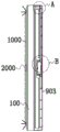
Fig. 1 is a front view of an embodiment of the solution according to the patent.
Fig. 2 is a cross-sectional view of an embodiment of the solution according to the patent.
Figure 3 is another cross-sectional view of an embodiment of the solution according to the patent.
Fig. 4 is a schematic diagram illustrating the matching of the moving block, the driving member and the camera module according to an embodiment of the present disclosure.
Fig. 5 is an enlarged schematic view of a portion a in fig. 3.
Fig. 6 is an enlarged schematic view of a portion B in fig. 3.
Detailed Description
In order to more clearly and fully illustrate the core concepts of the present invention, the invention will be further described and illustrated with reference to specific embodiments. It should be noted that the following specific embodiments are intended to illustrate the inventive concept and are not intended to limit the implementation of the present invention, so the implementation of the present invention includes but is not limited to what is described in the present application, and the replacement and avoidance by those skilled in the art according to the inventive concept should be considered as falling within the scope of the present invention which is claimed or should not be granted.
The sweeping robot comprises a robot shell, a control unit, a storage unit, a visual unit, an image processing and analyzing unit and a driving unit are arranged in the robot shell, the storage unit is not limited to one or more than one, the storage unit is used for storing an instruction set comprising an image processing and analyzing unit and a driving unit, a processor in the control unit calls and processes the instruction set in a memory through a memory controller, a corresponding judgment result is generated according to external input data and conditions and is output in the form of an instruction, the visual unit takes image information obtained by shooting at a shooting point as external condition input, then the processor obtains position and contour information of an obstacle in an image by calling the image processing and analyzing instruction set, then the processor calls a path planning instruction set again to calculate to obtain planning path information, and forms a corresponding driving unit instruction set according to the planning path information, for obstacle avoidance and directional speed adjustment.
The unit modules are provided with corresponding circuits correspondingly, for example, the driving unit comprises a driving circuit, the driving circuit comprises one or more micro motors, and the one or more micro motors are used for providing a power source for the driving mechanism and completing corresponding actions under the instruction. The units can be integrated on a circuit board through a microelectronic circuit or an integrated circuit and are installed in the robot shell, a walking unit 2000 for walking and a cleaning roller 1000 for cleaning are positioned below the robot shell, and a driving circuit part of the driving unit drives the walking unit and the cleaning unit through a power source such as a motor through a command sent by the control unit.
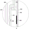
The robot housing includes a base 100 in the shape of a circular disc, the base 100 includes a cylindrical table with a reduced diameter, and a corresponding cover 903 is secured to the cylindrical table at a shoulder formed by the cylindrical table by means including, but not limited to, screws. The space that is used for movable block 200 to remove is formed between the flange of lid 903 downwardly extending and the outer peripheral face of cylinder platform, the outer peripheral face of the cylinder platform that corresponds sets up ball track 800, the support frame includes a plurality of rings with the ball one-to-one, the internal diameter of ring slightly is less than the diameter of ball, the support frame is fixed in the outer peripheral face department of cylinder platform through the mode of screw or bonding, movable block 200 is more smooth when moving along the cylinder platform outer peripheral face, and the accessible is scribbled and is established paste lubricating grease and realize better silence performance. The moving block 200 is an L-shaped structure, an arc inner side surface corresponding to the arc profile of the base 100 is arranged at one side of the moving block 200, and the balls freely roll in the support frame and are in contact fit with the arc inner side surface. The other side of the moving block 200 extends to the upper side of the upper surface of the cylindrical table to form a structure pointing to the center of the cylindrical table, the mounting hole 201 is located at the joint of two sides of the moving block 200, an opening structure is arranged above the mounting hole 201, the camera module 400 is located in the mounting hole 201, the upper end surface of the camera module 400 is exposed out of the opening position of the mounting hole 201, in the embodiment shown in the figure, the mounting hole 201 and the camera module 400 are of corresponding cylindrical structures and are coaxially mounted during mounting, the inner surface of the mounting hole 201 is in clearance fit with the outer peripheral surface of the camera module 400, and a structure that the camera module 400 can freely rotate in the mounting hole 201 is formed; in order to avoid the occurrence of black shadows in the pictures taken by the camera modules 400, the cameras of the corresponding camera modules 400 should protrude out of the outer peripheral surface of the moving block 200, the corresponding moving block 200 is further provided with a yielding hole 202 for yielding the cameras of the camera modules 400, the yielding hole 202 is a long-strip-shaped groove structure transversely arranged along the outer side surface of the moving block, and the cameras are located in the long-strip-shaped groove.
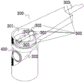
The driving mechanism is configured to adjust the positions of the camera module 400 and the moving block 200, and includes a micro driving motor 500 for providing power, in this embodiment, the micro driving motor 500 is a dual output shaft motor, one output shaft is used for adjusting the position of the camera module 400, and the other output shaft is used for adjusting the positions of the moving block 200 and the micro driving motor 500. In the above or some embodiments, the driving mechanism further comprises a micro driving motor 500, the driving motor 500 is located at the center of the base 100 and configured to drive the base 100 to rotate around the central axis, and a power transmission mechanism is disposed between the driving member 300 and the driving motor 500. The driving mechanism further includes a driving member 300, and the driving member 300 is configured to drive the camera module 400 to rotate around the set axis while moving along the outer peripheral surface of the base 100 with the moving block 200.
In the above or some embodiments, the driving shaft 303 is fixedly connected to one output shaft of the driving motor 500, and a gear mechanism is disposed between the other output shaft of the driving motor 500 and the base 100 in a matching manner, and includes an annular internal gear 600 fixed on the base 100, and further includes a bevel gear 700 fixedly connected to the output shaft of the driving motor 500, so as to form a structure in which the driving motor 500 drives the bevel gear 700 to rotate around the axis of the annular internal gear 600.
In the above or some embodiments, the driving member 300 is configured to drive the camera module 400 to periodically swing around the set axis while moving along the outer circumferential surface of the base 100 with the moving block 200. Specifically, the driving member 300 includes a friction disc 301 fixedly connected to the top of the camera module 400 and having a conical surface, and two friction heads 302 engaged with the friction disc 301, where the two friction heads 302 are located above the friction disc 301, the two friction heads 302 respectively include conical friction surfaces frictionally engaged with the surface of the friction disc 301, the two friction heads 302 are located on the same straight line and driven by the same driving shaft 303, the driving shaft 303 passes through the axial position of the friction disc 301, and when one friction head 302 is frictionally engaged with the friction disc 301, the other friction head 302 is disengaged from the friction disc 301, so as to form a structure in which the two friction heads 302 periodically frictionally act on the friction disc 301.
In the above or some embodiments, the cover device further includes a cover 900, the cover 900 includes a pointer portion 901 and a disc portion 902, the pointer portion 901 is located above the driving shaft 303, the disc portion 902 is located above the driving motor 500, a disc-shaped cover 903 is further covered above the corresponding base 100, the cover 903 is made of a transparent material, and the cover 900 is fixedly connected to a lower surface of the cover 903.
When the device is used in detail, an output shaft of the driving motor 500 drives the bevel gear 700 to move on the internal gear 600 engaged with the bevel gear, a turntable 501 arranged below the driving motor 500 and used for mounting the driving motor 500 rotates along with the driving motor 500, a conductive slip ring is arranged below the turntable in order to provide power source and signal control for the driving motor 500, the conductive slip ring 502 is connected with a driving circuit and a control unit part to form a structure for driving and controlling the driving motor 500, when the driving motor 500 rotates along with the turntable, the driving motor 500 drives the driving shaft 303 to rotate around a turntable axis, meanwhile, the driving shaft 303 rotates by itself under the driving of the driving motor 500 and drives the friction head 302 to rotate, when the moving block 200 moves from one shooting point to the next shooting point, the friction head 302 on the driving shaft 303 drives the camera module 400 to rotate to realize periodic swinging relative to a dead angle range, having obtained the image information of the dead angle region, the period of the above-mentioned periodic wobbling should be smaller than the time from one shot point to the next shot point of the moving block 200.