Disclosure of Invention
In order to overcome the defects of overlarge occupied space and uneven watering of the existing greenhouse planting frame, the technical problem to be solved is as follows: the greenhouse three-dimensional planting frame can change the space occupied by the planting frame and realize uniform watering.
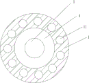
The technical scheme is as follows: a greenhouse stereoscopic planting frame comprises a support, an adjusting device, a planting disc, a first bearing, a first rotating shaft, fixing plates, a second spring, a second sliding rod and a second clamping wheel, wherein 2 fixing plates are connected above the support through the first bearing and the first rotating shaft, the fixing plates are vertically arranged, the first bearing is arranged at the top of the support and at the top of the middle fixing plate, the first rotating shaft is arranged in the first bearing, the top end of the first rotating shaft is connected with the bottom of the fixing plates, the adjusting device is arranged at the upper part and the lower part of the support and the upper part and the lower part of the fixing plates, the outer end of the adjusting device is connected with the planting disc, arc grooves are uniformly formed at the top of the support and at the top of the middle fixing plate, a second sliding groove is formed at the lower side of the right part of each fixing plate, the top in the second sliding groove is connected with the second spring, the bottom of the second spring is connected with the second sliding, the second clamping wheel is matched with the arc-shaped groove.
In addition, particularly preferably, the adjusting device comprises a guide rod, a first baffle, a first slide rod, a second baffle, a first spring and a first clamping wheel, wherein guide holes are formed in the upper part and the lower part of the support and the fixing plate, the guide rod is arranged in the guide holes in a sliding manner, one end of the guide rod is connected with the first baffle, the other end of the guide rod is connected with the planting plate, first clamping grooves are formed in the outer side of the bottom of the guide rod, second clamping grooves are formed in the inner side of the bottom of the guide rod, grooves are formed in the upper part and the lower part of the support and the fixing plate, the grooves are located below the guide holes, first sliding grooves are formed in the upper part and the lower part of the support and the fixing plate, the first sliding grooves are located below the grooves, the first sliding grooves are communicated with the grooves, a first slide rod is arranged in the first sliding manner, the upper part of the first slide rod is connected with the second baffle, a first spring is connected between the second, the top rotary type of first slide bar is connected with first calorie of wheel, and first calorie of wheel cooperates with first draw-in groove or second draw-in groove.
In addition, particularly preferably, the device also comprises a second rotating shaft, a driving motor, a support plate, a second bearing, a water tank, a first water pipe, a first electromagnetic valve, a second electromagnetic valve, a soil moisture sensor, a soil temperature sensor, a buzzer, a control box, a display screen and a control panel, wherein the top of the uppermost fixing plate is connected with the second rotating shaft, the top end of the second rotating shaft is provided with the driving motor, the support plate is arranged on the driving motor, the bottom of the support plate is provided with the second bearing, the second rotating shaft is connected with an inner ring of the second bearing, the top of the support plate is connected with the water tank, the left wall and the right wall of the water tank are both connected with the first water pipe, the first electromagnetic valve is arranged at the upper part of the first water pipe on the right side, the second electromagnetic valve is arranged at the upper part of the first water pipe on the left side, the left wall in, buzzer is installed on the bottom right side of support, the control box is located buzzer's right side, including power module in the control box, switching power supply and control module, the display screen is installed on the antetheca upper portion of control box, control panel is installed to the antetheca lower part of control box, including setting up the key on the control panel, add 1 key, subtract 1 key and enter key, driving motor, soil moisture sensor, soil temperature sensor and buzzer all are connected with control module through the circuit.
In addition, particularly preferably, the device also comprises a bracket, a spray pipe, a support rod and a first spray motor, the third bearing, the third pivot, flabellum and second spraying motor, the upper portion left and right sides of extension board all is connected with the support, the bottom of support is connected with the spray tube, open on the outer wall upper portion of spray tube has first through-hole, the bottom UNICOM of first through-hole and first water pipe, open the inner wall of spray tube has the second through-hole, the top left and right sides of spray tube all is connected with branch, install first spraying motor between the branch on the spray tube of left side, install second spraying motor between the branch on the spray tube of right side, install the third bearing on the roof of spray tube, all install the third pivot on the output shaft of first spraying motor and second spraying motor, the third bearing is passed in the third pivot, the end of third pivot all is connected with the flabellum, first spraying motor and second spraying motor all are connected with control module through the circuit.
In addition, it is especially preferred that, still include level sensor, water pump, second water pipe and third water pipe, level sensor is installed to left wall lower part in the water tank, and the water pump is installed on the rightmost side in bottom of support, installs second water pipe and third water pipe on the water pump, and the third water pipe is located the second water pipe top, and the end of third water pipe is located the top right side of water tank, and level sensor and water pump all are connected with control module through the circuit.
The invention has the beneficial effects that: the automatic watering device has the advantages that the occupied space of the planting frame can be changed, the effect of uniform watering can be realized, the planting tray capable of moving left and right and rotating is arranged, the occupied space of the device can be flexibly changed, the water tank and the soil moisture sensor capable of rotating are arranged, uniform watering can be intelligently realized, manual operation is not needed, the liquid level sensor and the water pump are arranged, water addition can be automatically realized, and the automatic watering device is convenient and flexible to use.
Detailed Description
In order to make the objects, technical solutions and advantages of the present invention more apparent, the present invention will be described in further detail with reference to the accompanying drawings in conjunction with the following detailed description. It should be understood that the description is intended to be exemplary only, and is not intended to limit the scope of the present invention. Moreover, in the following description, descriptions of well-known structures and techniques are omitted so as to not unnecessarily obscure the concepts of the present invention.
Example 1
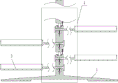
A greenhouse three-dimensional planting frame is shown in figures 1-7 and comprises a support 1, an adjusting device 2, a planting disc 3, a first bearing 4, a first rotating shaft 5, a fixing plate 6, a second spring 8, a second sliding rod 9 and a second clamping wheel 10, wherein 2 fixing plates 6 are connected above the support 1 through the first bearing 4 and the first rotating shaft 5, the fixing plates 6 are vertically arranged, the first bearing 4 is installed at the top of the support 1 and the top of the middle fixing plate 6, the first rotating shaft 5 is installed in the first bearing 4, the first rotating shaft 5 is connected with the first bearing 4 in an interference connection mode, the top end of the first rotating shaft 5 is connected with the bottom of the fixing plate 6, the first rotating shaft 5 is connected with the fixing plate 6 in a welding connection mode, the upper portion and the lower portion of the support 1 and the fixing plate 6 are both provided with the adjusting device 2, the outer end of the adjusting device 2 is connected with the planting disc 3, arc-shaped grooves 11 are uniformly formed in the top of the support 1 and the top of the middle, second spout 7 has all been opened to the right part downside of every fixed plate 6, and the top all is connected with second spring 8 in the second spout 7, and second spring 8's bottom all is connected with second slide bar 9, and second spring 8 passes through welded connection's mode and is connected with second slide bar 9, and second card wheel 10 is installed to the bottom of second slide bar 9, and second card wheel 10 cooperates with arc wall 11.
Example 2
A greenhouse stereoscopic planting frame is shown in figures 1-7 and comprises a support 1, an adjusting device 2, a planting tray 3, a first bearing 4, a first rotating shaft 5, a fixing plate 6, a second spring 8, a second sliding rod 9 and a second clamping wheel 10, wherein the upper part of the support 1 is connected with 2 fixing plates 6 through the first bearing 4 and the first rotating shaft 5, the fixing plates 6 are vertically arranged, the first bearing 4 is arranged at the top of the support 1 and the top of the middle fixing plate 6, the first rotating shaft 5 is arranged in the first bearing 4, the top end of the first rotating shaft 5 is connected with the bottom of the fixing plate 6, the upper part and the lower part of the support 1 and the upper part and the lower part of the fixing plate 6 are respectively provided with the adjusting device 2, the outer end of each adjusting device 2 is connected with the planting tray 3, arc-shaped grooves 11 are uniformly formed at the top of the support 1 and the top of the middle fixing plate 6, the lower side of the right part, the top all is connected with second spring 8 in the second spout 7, and the bottom of second spring 8 all is connected with second slide bar 9, and second card wheel 10 is installed to the bottom of second slide bar 9, and second card wheel 10 cooperates with arc wall 11.
The adjusting device 2 comprises a guide rod 202, a first baffle plate 203, a first sliding rod 208, a second baffle plate 209, a first spring 210 and a first clamping wheel 211, wherein the upper part and the lower part of the support 1 and the fixing plate 6 are both provided with guide holes 201, the guide holes 201 are internally provided with the guide rod 202 in a sliding manner, one end of the guide rod 202 is connected with the first baffle plate 203, the guide rod 202 is connected with the first baffle plate 203 in a welding connection manner, the other end of the guide rod 202 is connected with the planting disc 3, the guide rod 202 is connected with the planting disc 3 in a welding connection manner, the outer side of the bottom of the guide rod 202 is provided with a first clamping groove 204, the inner side of the bottom of the guide rod 202 is provided with a second clamping groove 205, the upper part and the lower part of the support 1 and the fixing plate 6 are both provided with grooves 206, the grooves 206 are positioned below the guide holes 201, the upper part and the lower part of the support 1 and the fixing plate 6 are both provided with, the first sliding groove 207 is communicated with the groove 206, a first sliding rod 208 is arranged in the first sliding groove 207 in a sliding manner, the upper portion of the first sliding rod 208 is connected with a second baffle 209, the first sliding rod 208 is connected with the second baffle 209 in a welding connection manner, a first spring 210 is connected between the second baffle 209 and the bottom wall of the groove 206, the first spring 210 bypasses the first sliding rod 208, a first clamp wheel 211 is rotatably connected to the top of the first sliding rod 208, and the first clamp wheel 211 is matched with the first clamp groove 204 or the second clamp groove 205.
Example 3
A greenhouse stereoscopic planting frame is shown in figures 1-7 and comprises a support 1, an adjusting device 2, a planting tray 3, a first bearing 4, a first rotating shaft 5, a fixing plate 6, a second spring 8, a second sliding rod 9 and a second clamping wheel 10, wherein the upper part of the support 1 is connected with 2 fixing plates 6 through the first bearing 4 and the first rotating shaft 5, the fixing plates 6 are vertically arranged, the first bearing 4 is arranged at the top of the support 1 and the top of the middle fixing plate 6, the first rotating shaft 5 is arranged in the first bearing 4, the top end of the first rotating shaft 5 is connected with the bottom of the fixing plate 6, the upper part and the lower part of the support 1 and the upper part and the lower part of the fixing plate 6 are respectively provided with the adjusting device 2, the outer end of each adjusting device 2 is connected with the planting tray 3, arc-shaped grooves 11 are uniformly formed at the top of the support 1 and the top of the middle fixing plate 6, the lower side of the right part, the top all is connected with second spring 8 in the second spout 7, and the bottom of second spring 8 all is connected with second slide bar 9, and second card wheel 10 is installed to the bottom of second slide bar 9, and second card wheel 10 cooperates with arc wall 11.
The adjusting device 2 comprises a guide rod 202, a first baffle plate 203, a first sliding rod 208, a second baffle plate 209, a first spring 210 and a first clamping wheel 211, wherein the upper part and the lower part of the support 1 and the fixing plate 6 are both provided with guide holes 201, the guide holes 201 are internally provided with the guide rod 202 in a sliding manner, one end of the guide rod 202 is connected with the first baffle plate 203, the other end of the guide rod 202 is connected with the planting disc 3, the outer sides of the bottoms of the guide rods 202 are both provided with first clamping grooves 204, the inner sides of the bottoms of the guide rods 202 are both provided with second clamping grooves 205, the upper part and the lower part of the support 1 and the fixing plate 6 are both provided with grooves 206, the grooves 206 are positioned below the guide holes 201, the upper part and the lower part of the support 1 and the fixing plate 6 are both provided with first sliding grooves 207, the first sliding grooves 207 are positioned below the grooves 206, the first sliding grooves 207 are communicated with the grooves 206, the first sliding rod 208 is internally provided with the first, a first spring 210 is connected between the second baffle 209 and the bottom wall of the groove 206, the first spring 210 bypasses the first sliding rod 208, a first catch wheel 211 is rotatably connected to the top of the first sliding rod 208, and the first catch wheel 211 is matched with the first catch groove 204 or the second catch groove 205.
The soil temperature sensor further comprises a second rotating shaft 12, a driving motor 13, a support plate 14, a second bearing 15, a water tank 16, a first water pipe 17, a first electromagnetic valve 18, a second electromagnetic valve 19, a soil moisture sensor 20, a soil temperature sensor 21, a buzzer 22, a control box 23, a display screen 24 and a control panel 25, wherein the top of the uppermost fixing plate 6 is connected with the second rotating shaft 12, the driving motor 13 is installed at the top end of the second rotating shaft 12, the support plate 14 is installed on the driving motor 13, the driving motor 13 is connected with the support plate 14 in a bolt connection mode, the second bearing 15 is installed at the bottom of the support plate 14, the second rotating shaft 12 is connected with an inner ring of the second bearing 15, the water tank 16 is connected at the top of the support plate 14, the support plate 14 is connected with the water tank 16 in a bolt connection mode, the left wall and the right wall of the water tank 16 are both connected with the first water pipe, the upper parts of the first water pipes 17 on the left side are respectively provided with a second electromagnetic valve 19, the left wall in the planting tray 3 on the right side of the middle fixing plate 6 is connected with a soil moisture sensor 20, the right wall in the planting tray 3 on the right side of the middle fixing plate 6 is connected with a soil temperature sensor 21, the right side of the bottom of the support 1 is provided with a buzzer 22, the right side of the bottom of the support 1 is provided with a control box 23, the support 1 is connected with the control box 23 in a bolt connection mode, the control box 23 is positioned on the right side of the buzzer 22, the control box 23 comprises a power module, a switching power supply and a control module, the upper part of the front wall of the control box 23 is provided with a display screen 24, the lower part of the front wall of the control, and a minus 1 key and a confirmation key, wherein the driving motor 13, the soil moisture sensor 20, the soil temperature sensor 21 and the buzzer 22 are all connected with the control module through lines.
Example 4
A greenhouse stereoscopic planting frame is shown in figures 1-7 and comprises a support 1, an adjusting device 2, a planting tray 3, a first bearing 4, a first rotating shaft 5, a fixing plate 6, a second spring 8, a second sliding rod 9 and a second clamping wheel 10, wherein the upper part of the support 1 is connected with 2 fixing plates 6 through the first bearing 4 and the first rotating shaft 5, the fixing plates 6 are vertically arranged, the first bearing 4 is arranged at the top of the support 1 and the top of the middle fixing plate 6, the first rotating shaft 5 is arranged in the first bearing 4, the top end of the first rotating shaft 5 is connected with the bottom of the fixing plate 6, the upper part and the lower part of the support 1 and the upper part and the lower part of the fixing plate 6 are respectively provided with the adjusting device 2, the outer end of each adjusting device 2 is connected with the planting tray 3, arc-shaped grooves 11 are uniformly formed at the top of the support 1 and the top of the middle fixing plate 6, the lower side of the right part, the top all is connected with second spring 8 in the second spout 7, and the bottom of second spring 8 all is connected with second slide bar 9, and second card wheel 10 is installed to the bottom of second slide bar 9, and second card wheel 10 cooperates with arc wall 11.
The adjusting device 2 comprises a guide rod 202, a first baffle plate 203, a first sliding rod 208, a second baffle plate 209, a first spring 210 and a first clamping wheel 211, wherein the upper part and the lower part of the support 1 and the fixing plate 6 are both provided with guide holes 201, the guide holes 201 are internally provided with the guide rod 202 in a sliding manner, one end of the guide rod 202 is connected with the first baffle plate 203, the other end of the guide rod 202 is connected with the planting disc 3, the outer sides of the bottoms of the guide rods 202 are both provided with first clamping grooves 204, the inner sides of the bottoms of the guide rods 202 are both provided with second clamping grooves 205, the upper part and the lower part of the support 1 and the fixing plate 6 are both provided with grooves 206, the grooves 206 are positioned below the guide holes 201, the upper part and the lower part of the support 1 and the fixing plate 6 are both provided with first sliding grooves 207, the first sliding grooves 207 are positioned below the grooves 206, the first sliding grooves 207 are communicated with the grooves 206, the first sliding rod 208 is internally provided with the first, a first spring 210 is connected between the second baffle 209 and the bottom wall of the groove 206, the first spring 210 bypasses the first sliding rod 208, a first catch wheel 211 is rotatably connected to the top of the first sliding rod 208, and the first catch wheel 211 is matched with the first catch groove 204 or the second catch groove 205.
The soil moisture sensor is characterized by further comprising a second rotating shaft 12, a driving motor 13, a support plate 14, a second bearing 15, a water tank 16, a first water pipe 17, a first electromagnetic valve 18, a second electromagnetic valve 19, a soil moisture sensor 20, a soil temperature sensor 21, a buzzer 22, a control box 23, a display screen 24 and a control panel 25, wherein the top of the uppermost fixing plate 6 is connected with the second rotating shaft 12, the top end of the second rotating shaft 12 is provided with the driving motor 13, the support plate 14 is arranged on the driving motor 13, the bottom of the support plate 14 is provided with the second bearing 15, the second rotating shaft 12 is connected with an inner ring of the second bearing 15, the top of the support plate 14 is connected with the water tank 16, the left wall and the right wall of the water tank 16 are both connected with the first water pipe 17, the first electromagnetic valve 18 is arranged at the upper part of the first water pipe 17 on the right side, the second electromagnetic valve 19 is arranged at the upper part of the, right wall connection has soil temperature sensor 21 in the planting dish 3 on middle fixed plate 6 right side, bee calling organ 22 is installed on the bottom right side of support 1, control box 23 is located bee calling organ 22's right side, including power module in the control box 23, switching power supply and control module, display screen 24 is installed on the antetheca upper portion of control box 23, control panel 25 is installed to the antetheca lower part of control box 23, including setting up the key on control panel 25, add 1 key, subtract 1 key and enter key, driving motor 13, soil moisture sensor 20, soil temperature sensor 21 and bee calling organ 22 are all connected with control module through the circuit.
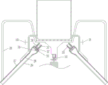
The spraying device also comprises a bracket 26, a spraying pipe 27, supporting rods 30, a first spraying motor 31, a third bearing 32, a third rotating shaft 33, fan blades 34 and a second spraying motor 35, wherein the bracket 26 is connected to the left side and the right side of the upper part of the supporting plate 14, the supporting plate 14 is connected with the bracket 26 in a bolt connection mode, the spraying pipe 27 is connected to the bottom end of the bracket 26, a first through hole 28 is formed in the upper part of the outer wall of the spraying pipe 27, the first through hole 28 is communicated with the bottom of the first water pipe 17, a second through hole 29 is formed in the inner wall of the spraying pipe 27, the supporting rods 30 are connected to the left side and the right side of the top of the spraying pipe 27, the first spraying motor 31 is installed between the supporting rods 30 on the left side spraying pipe 27, the second spraying motor 35 is installed between the supporting rods 30 on the right side spraying pipe 27, the third bearing 32 is installed on the top wall of the spraying pipe 27, the third rotating, third pivot 33 is connected with third bearing 32 through interference connection's mode, and the end of third pivot 33 all is connected with flabellum 34, and third pivot 33 is connected with flabellum 34 through welded connection's mode, and first spraying motor 31 and second spraying motor 35 all are connected with control module through the circuit.
Example 5
A greenhouse stereoscopic planting frame is shown in figures 1-7 and comprises a support 1, an adjusting device 2, a planting tray 3, a first bearing 4, a first rotating shaft 5, a fixing plate 6, a second spring 8, a second sliding rod 9 and a second clamping wheel 10, wherein the upper part of the support 1 is connected with 2 fixing plates 6 through the first bearing 4 and the first rotating shaft 5, the fixing plates 6 are vertically arranged, the first bearing 4 is arranged at the top of the support 1 and the top of the middle fixing plate 6, the first rotating shaft 5 is arranged in the first bearing 4, the top end of the first rotating shaft 5 is connected with the bottom of the fixing plate 6, the upper part and the lower part of the support 1 and the upper part and the lower part of the fixing plate 6 are respectively provided with the adjusting device 2, the outer end of each adjusting device 2 is connected with the planting tray 3, arc-shaped grooves 11 are uniformly formed at the top of the support 1 and the top of the middle fixing plate 6, the lower side of the right part, the top all is connected with second spring 8 in the second spout 7, and the bottom of second spring 8 all is connected with second slide bar 9, and second card wheel 10 is installed to the bottom of second slide bar 9, and second card wheel 10 cooperates with arc wall 11.
The adjusting device 2 comprises a guide rod 202, a first baffle plate 203, a first sliding rod 208, a second baffle plate 209, a first spring 210 and a first clamping wheel 211, wherein the upper part and the lower part of the support 1 and the fixing plate 6 are both provided with guide holes 201, the guide holes 201 are internally provided with the guide rod 202 in a sliding manner, one end of the guide rod 202 is connected with the first baffle plate 203, the other end of the guide rod 202 is connected with the planting disc 3, the outer sides of the bottoms of the guide rods 202 are both provided with first clamping grooves 204, the inner sides of the bottoms of the guide rods 202 are both provided with second clamping grooves 205, the upper part and the lower part of the support 1 and the fixing plate 6 are both provided with grooves 206, the grooves 206 are positioned below the guide holes 201, the upper part and the lower part of the support 1 and the fixing plate 6 are both provided with first sliding grooves 207, the first sliding grooves 207 are positioned below the grooves 206, the first sliding grooves 207 are communicated with the grooves 206, the first sliding rod 208 is internally provided with the first, a first spring 210 is connected between the second baffle 209 and the bottom wall of the groove 206, the first spring 210 bypasses the first sliding rod 208, a first catch wheel 211 is rotatably connected to the top of the first sliding rod 208, and the first catch wheel 211 is matched with the first catch groove 204 or the second catch groove 205.
The soil moisture sensor is characterized by further comprising a second rotating shaft 12, a driving motor 13, a support plate 14, a second bearing 15, a water tank 16, a first water pipe 17, a first electromagnetic valve 18, a second electromagnetic valve 19, a soil moisture sensor 20, a soil temperature sensor 21, a buzzer 22, a control box 23, a display screen 24 and a control panel 25, wherein the top of the uppermost fixing plate 6 is connected with the second rotating shaft 12, the top end of the second rotating shaft 12 is provided with the driving motor 13, the support plate 14 is arranged on the driving motor 13, the bottom of the support plate 14 is provided with the second bearing 15, the second rotating shaft 12 is connected with an inner ring of the second bearing 15, the top of the support plate 14 is connected with the water tank 16, the left wall and the right wall of the water tank 16 are both connected with the first water pipe 17, the first electromagnetic valve 18 is arranged at the upper part of the first water pipe 17 on the right side, the second electromagnetic valve 19 is arranged at the upper part of the, right wall connection has soil temperature sensor 21 in the planting dish 3 on middle fixed plate 6 right side, bee calling organ 22 is installed on the bottom right side of support 1, control box 23 is located bee calling organ 22's right side, including power module in the control box 23, switching power supply and control module, display screen 24 is installed on the antetheca upper portion of control box 23, control panel 25 is installed to the antetheca lower part of control box 23, including setting up the key on control panel 25, add 1 key, subtract 1 key and enter key, driving motor 13, soil moisture sensor 20, soil temperature sensor 21 and bee calling organ 22 are all connected with control module through the circuit.
The spraying device also comprises a bracket 26, a spraying pipe 27, supporting rods 30, a first spraying motor 31, a third bearing 32, a third rotating shaft 33, fan blades 34 and a second spraying motor 35, wherein the bracket 26 is connected to the left side and the right side of the upper part of the supporting plate 14, the spraying pipe 27 is connected to the bottom end of the bracket 26, a first through hole 28 is formed in the upper part of the outer wall of the spraying pipe 27, the first through hole 28 is communicated with the bottom of the first water pipe 17, a second through hole 29 is formed in the inner wall of the spraying pipe 27, the supporting rods 30 are connected to the left side and the right side of the top of the spraying pipe 27, the first spraying motor 31 is installed between the supporting rods 30 on the left side spraying pipe 27, the second spraying motor 35 is installed between the supporting rods 30 on the right side spraying pipe 27, the third bearing 32 is installed on the top wall of the spraying pipe 27, the third rotating shaft 33 penetrates through the third bearing 32, the tail end of the third, the first spraying motor 31 and the second spraying motor 35 are connected with the control module through lines.
Still including level sensor 36, water pump 37, second water pipe 38 and third water pipe 39, level sensor 36 is installed to left wall lower part in the water tank 16, water pump 37 is installed to the rightmost side in bottom of support 1, support 1 is connected with water pump 37 through bolted connection's mode, install second water pipe 38 and third water pipe 39 on the water pump 37, third water pipe 39 is located second water pipe 38 top, the end of third water pipe 39 is located the top right side of water tank 16, level sensor 36 and water pump 37 all are connected with control module through the circuit.
When plants need to be planted in the planting plate 3, a worker firstly pulls the planting plates 3 at various positions to move outwards, and after being pulled to a certain position, the planting disk 3 can be fixed through the adjusting device 2 so as to improve the stability of the fixation of the planting disk 3, and in order to make the plants in the planting plate 3 in each position receive the illumination, the worker can rotate the angle of the planting plate 3, when external force is applied to the planting plate 3 to change the angle, the second spring 8 is compressed, the second clamping wheel 10 moves upwards and rotates out of the corresponding arc-shaped groove 11, when the second clamping wheel 10 is positioned above the other arc-shaped groove 11, under the elastic force effect of the second spring 8, the second clamping wheel 10 moves downwards to be clamped in the arc-shaped groove 11 below, and the angle of the planting plate 3 can be flexibly changed by repeated operation, so that the angle of the planting plate 3 can be fixed and the angle can also be flexibly changed. When the device is not needed, the worker can enable the planting plates 3 at all positions to move towards the inner side, the planting plates 3 are stopped to be pushed after the worker moves to the initial position, and the adjusting device 2 can fix the planting plates 3 after the worker returns to the initial position, so that the occupied space of the device can be saved when the device is not used, and the device is convenient to use.
When the pulling planting disc 3 moves to the outside, the guide rod 202 moves to the outside, the first spring 210 can be compressed, the first clamping wheel 211 moves downwards, the first clamping wheel 211 is separated from the first clamping groove 204, when the guide rod 202 moves to the outside to enable the second clamping groove 205 to be located right above the first clamping wheel 211, under the elastic action of the first spring 210, the first clamping wheel 211 moves upwards, the first clamping wheel 211 is clamped into the second clamping groove 205, the pulling of the planting disc 3 is stopped at the moment, the position of the planting disc 3 can be fixed, and the first baffle plate 203 can prevent the guide rod 202 from being separated from the guide hole 201 due to the fact that the worker exerts too much force. When promoting planting dish 3 and moving to the inboard, guide bar 202 moves to the inboard, first spring 210 can be compressed, first calorie of wheel 211 moves downwards, first calorie of wheel 211 breaks away from second draw-in groove 205, when guide bar 202 moves to the inboard and makes first draw-in groove 204 be located first calorie of wheel 211 directly over, under the spring action of first spring 210, first calorie of wheel 211 moves upwards, first calorie of wheel 211 card advances in first draw-in groove 204, stop promoting planting dish 3 this moment, can fix the position of planting dish 3 like this.
Plant the plant after filling into soil in planting dish 3, soil can cover soil moisture sensor 20 and soil temperature sensor 21, and soil temperature sensor 21 can sense the temperature in the soil to control module is given in the signals, and control module shows temperature information at display screen 24, and the staff can in time know the temperature in the soil like this, is convenient for in time regulate and control. The soil moisture sensor 20 can sense the humidity in the soil, when the moisture value sensed by the soil moisture sensor 20 is lower than the preset value in the control module, the soil moisture sensor 20 sends a signal to the control module, the control module controls the driving motor 13 to start working, at the moment, the second rotating shaft 12 is fixed, the driving motor 13, the supporting plate 14, the water tank 16 and the first water pipe 17 start to rotate clockwise, and simultaneously the control module controls the first electromagnetic valve 18 and the second electromagnetic valve 19 to open, the water in the water tank 16 flows out through the first water pipes 17 on the left side and the right side, and then falls into the planting tray 3, after the driving motor 13 works for 5 seconds, the control module controls the output shaft of the driving motor 13 to start to rotate counterclockwise, the driving motor 13, the supporting plate 14, the water tank 16 and the first water pipe 17 start to rotate counterclockwise, and then after the output shaft of the driving motor 13 rotates counterclockwise for 5 seconds, the control module controls the output shaft of the driving motor 13 to rotate clockwise for 5 seconds, and repeats the steps until the driving motor 13 stops working when the total working time of the driving motor 13 is 4 minutes, and controls the first electromagnetic valve 18 and the second electromagnetic valve 19 to close. There will be sufficient water in the soil and the value of the water in the soil will be displayed on the display screen 24. In this way, the plants are not required to be watered manually, and the intelligent watering device is more intelligent and convenient. The time period of the operation of the driving motor 13 and the preset value of the moisture of the soil moisture sensor 20 in the control module can be adjusted by the setting key, the plus 1 key, the minus 1 key and the confirmation key in the control panel 25, so as to be suitable for the planting of different plants.
When control module control driving motor 13 began work, control module control first spraying motor 31 and second spraying motor 35 began work, the output shaft of first spraying motor 31 and second spraying motor 35 drives third pivot 33 and flabellum 34 and begins to rotate, rotatory flabellum 34 can produce wind, water in the water tank 16 enters into spray tube 27 through first water pipe 17 and first through-hole 28 in, and fall out by second through-hole 29, the wind that flabellum 34 produced can blow off the water in the spray tube 27, the scope that makes the water spray is bigger, so that more even plant to in the planting dish 3 waters, do benefit to the growth of plant. While the control module controls the driving motor 13 to stop operating, the control module controls the first and second spray motors 31 and 35 to stop operating.
When the liquid level of the water in the water tank 16 is lower than the height of the liquid level sensor 36, the liquid level sensor 36 sends a signal to the control module, the control module controls the water pump 37 to start working, the water pump 37 pumps the outside water into the water tank 16 through the second water pipe 38 and the third water pipe 39, and after the water pump 37 works for 8 minutes, the control module controls the water pump 37 to stop working. Therefore, water is not required to be added manually, and the device is convenient and practical.
The above description is only for the specific embodiments of the present invention, but the scope of the present invention is not limited thereto, and any person skilled in the art can easily conceive of the changes or substitutions within the technical scope of the present invention, and all the changes or substitutions should be covered within the scope of the present invention. Therefore, the protection scope of the present invention shall be subject to the protection scope of the claims.