CN109664903B - Multifunctional railway flatcar - Google Patents
Multifunctional railway flatcar Download PDFInfo
- Publication number
- CN109664903B CN109664903B CN201811444844.XA CN201811444844A CN109664903B CN 109664903 B CN109664903 B CN 109664903B CN 201811444844 A CN201811444844 A CN 201811444844A CN 109664903 B CN109664903 B CN 109664903B
- Authority
- CN
- China
- Prior art keywords
- vehicle body
- railway
- car
- track panel
- braking
- Prior art date
- Legal status (The legal status is an assumption and is not a legal conclusion. Google has not performed a legal analysis and makes no representation as to the accuracy of the status listed.)
- Active
Links
Images


Classifications
-
- B—PERFORMING OPERATIONS; TRANSPORTING
- B61—RAILWAYS
- B61D—BODY DETAILS OR KINDS OF RAILWAY VEHICLES
- B61D3/00—Wagons or vans
- B61D3/08—Flat wagons including posts or standards
Abstract
The invention discloses a railway multifunctional flat car which comprises a car body, bogies, a braking device, a container locking device, car body accessories, car coupler buffering devices, movable end side walls and a track panel support, wherein the container locking device is welded on the car body; and the movable end side wall and the track panel bracket are arranged on the vehicle body according to the specification of the loaded goods. The invention can adapt to the limiting function of track panels with different sizes, can utilize the line limitation to the maximum extent, reduce the floor height, load the number of the track panels to the maximum extent, and the upper part and the lower part of the guide post are of slope structures, thereby facilitating the installation of operators and the loading of the track panels; the end wall and the side wall can be interchanged, and operation and maintenance are convenient.
Description
Technical Field
The invention relates to a multifunctional railway freight flat wagon, and belongs to the technical field of railway transportation.
Background
The subway greatly relieves urban traffic jam in the global range, and is more popular in various countries. Subway maintenance has special vehicles for maintaining the line within the range of the subway. Along with the long service time of subways in many countries, the workload of maintaining the subways is increased, a large amount of ballast, equipment, track panels and the like are needed, and vehicles are transported into the subways from a goods yard outside the subways in the existing transportation mode and then loaded onto the subway vehicles to enter a tunnel for construction. At present, the subway vehicle and the national railway vehicle have differences in use standards, line requirements, speed, braking, limitation and the like, and no vehicle capable of meeting the requirements of the subway and the national railway line simultaneously exists. There is a need for a multifunctional transportation flat car that meets the requirements of subway and state railway lines to improve the efficiency and cost of subway maintenance.
Disclosure of Invention
The invention aims to solve the technical problem of providing a flat car which can run on a subway line and a national railway line and meet multifunctional transportation aiming at the defects in the prior art.
In order to solve the technical problem, the invention provides a railway multifunctional flat car which comprises a car body, bogies, a braking device, a container locking device, car body accessories, car coupler buffering devices, a movable end side wall and a track panel bracket, wherein the container locking device is welded on the car body; and the movable end side wall and the track panel bracket are arranged on the vehicle body according to the specification of the loaded goods.
The braking device comprises a wind braking device and a hand braking device, the hand braking device is spiral and can be operated on two sides of the train body, the wind braking device adopts a UIC standard braking system, and meanwhile, modules which are suitable for different speeds and deceleration requirements of subways are added to the system, so that the requirements of the subways and national railway lines on braking performance can be met simultaneously.
The car body is of an all-steel welded structure and comprises end beams, a traction beam, a sleeper beam, a middle beam, a small cross beam, a support beam, side beams and a large cross beam, wherein the middle beam is of a fish belly type structure, the sleeper beam and the cross beam are of a variable-section double-web box type structure, and the side beams are hot-rolled channel steel and are provided with rope bolt points; the car body is paved with a floor, and anti-skid pattern steel walking plates are arranged at two ends of the car body.
The bogie is arranged at the lower part of the sleeper beam and is connected with the car body through a center plate; the bogie is provided with a vertical shock absorber and is a welded bogie; each bogie is controlled by a separate relay valve and brake cylinder, enabling precise control of the braking force.
Four emergency brake valves are arranged at four corners of the vehicle and are used for emergency braking of the train under special conditions; the hand braking device is used on a national railway line, and meets the requirement of line parking gradient; the spring parking brake device is used in a subway line and limited by the fact that the hand brake device cannot be used in a tunnel space, and the spring parking brake device and the hand brake device are isolated from each other, so that misoperation is avoided.
The container locking device adopts a twistlock lifting lock, is provided with sixteen side beams and floors which are welded together respectively.
The car coupler buffering device comprises an automatic vertical head car coupler and side buffers, wherein the automatic vertical head car coupler is arranged on a draft sill, and the side buffers are arranged on two sides of an end beam; when the coupler is connected with the UIC railway freight car, the vertical coupler can be folded, and the side buffer acts; when the train is marshalled with a subway train, a vertical head coupler is adopted for coupling.
The movable end side wall comprises end walls, side walls, locking pins, pin shafts and connecting plates, the side walls are arranged in a shared manner, and the lower parts of the side walls are provided with mounting columns which are connected with column jacks on the side beams to mount the side walls and the side beams; one end of the connecting plate is provided with a long hole and is connected with the end wall through a pin shaft, and the other end of the connecting plate is provided with a square hook, and the size and the shape of the square hook are matched with the upper part of the side wall; the end walls are connected with the side walls through connecting plates, and the end walls are arranged at any longitudinal position of the vehicle body to form a half-box and half-flat-plate structure or a whole box structure; therefore, the end wall and the side wall adopt all-steel welding structures, are provided with assembling and disassembling holes and can be interchanged respectively.
The track panel support comprises a supporting seat, guide columns and a connecting chain, the supporting seat is provided with a plurality of mounting holes, the guide columns are mounted on the supporting seat according to the minimum distance between the steel rails on the track panel, and the guide columns are connected with the supporting seat through the connecting chain; the two ends of the guide post are provided with inclined plates, so that the support seat and the track panel can be conveniently inserted into the inclined plates; the track panel supports are arranged at two ends of the vehicle body and are fastened through a twistlock lifting lock on the vehicle body; the two ends of the track panel are inserted into the track panel bracket and placed on the vehicle body, and the fastening is realized through the rope fastening points and the fastening belts on the side beams.
Has the advantages that: the track panel bracket is provided with the mounting holes with different intervals, can adapt to the limiting function of track panels with different sizes, can utilize the line limitation to the maximum extent, reduce the height of a floor, load the number of the track panels to the maximum extent, and is convenient for an operator to mount and load the track panels as the upper part and the lower part of the guide column are of slope structures, thereby improving the working efficiency; the end wall and the side wall can be interchanged, and operation and maintenance are convenient. The invention can meet the running requirements of the subway and the national railway at the same time.
Drawings
FIG. 1 is a schematic structural view of the present invention;
FIG. 2 is a schematic structural view of the vehicle body of the present invention;
FIG. 3 is a schematic view of the installation of the free end side wall of the present invention;
FIG. 4 is a schematic structural view of the movable end side wall of the present invention;
FIG. 5 is a schematic structural view of the end wall of the present invention;
FIG. 6 is a schematic view of the connection between the end wall and the side wall according to the present invention;
FIG. 7 is a schematic view of the present invention with the end wall and the side wall separated;
FIG. 8 is a schematic view of the mounting of the track panel support of the present invention;
FIG. 9 is a schematic view of a track panel support of the present invention;
FIG. 10 is a schematic view of a supporting base according to the present invention;
fig. 11 is a schematic view of the installation of the track panel of the present invention.
In the figure: the device comprises a vehicle body 1, a bogie 2, a braking device 3, a container locking device 4, a vehicle body accessory 5, a coupler buffer device 6, a movable end side wall 7, a track panel support 8 and a track panel 9; 11 end beams, 12 traction beams, 13 sleeper beams, 14 middle beams, 15 small cross beams, 16 support beams, 17 side beams, 18 large cross beams, 19 floors and 20 running boards; 71 end wall, 72 side wall, 73 locking pin, 74 pin shaft and 75 connecting plate; 81 support seats, 82 guide posts and 83 are connected with chains.
Detailed Description
The present invention will be described in detail with reference to the accompanying drawings and examples.
Fig. 1 is a schematic structural diagram of the present invention.
The invention provides a novel railway multifunctional flat car, which comprises a car body 1, bogies 2, a braking device 3, a container locking device 4, car body accessories 5, a car coupler buffering device 6, a movable end side wall 7 and a track panel support 8, wherein the container locking device 4 is welded on the car body 1, the braking device 3 is arranged at the lower part of the car body 1, the car body accessories 5 are arranged at the end part and two sides of the car body 1, the car coupler buffering device 6 is arranged at two sides of the end part of the car body 1, and the two bogies 2 are respectively arranged at two ends of the lower part of the car body 1; the movable end side wall 7 and the track panel bracket 8 are arranged on the vehicle body 1 according to the specification of the loaded goods.
The braking device 3 comprises a wind braking device and a hand braking device, the hand braking device is spiral, the hand braking device can be operated on two sides of the vehicle body 1, and the wind braking device can meet the requirements of subway and national railway lines on braking performance.
The braking device 3 adopts a novel control valve, and can meet the requirements of different braking performances of the subway and the state railway. The control valve is developed based on UIC mature modules, on the premise of meeting the requirement of subway braking performance, modules are added to meet the requirement of subway braking performance, and the braking modes of the subway (G/P) and the subway (LU) are switched through a G/P/LU conversion device, so that the compatibility of two different braking systems on one vehicle is realized. In addition, four emergency brake valves are arranged at four corners of the vehicle and are used for emergency braking of the train in special conditions. The hand braking device is used on a state railway line, and meets the parking gradient requirement of the state railway line; the spring parking brake device is used in a subway line and limited by the fact that the hand brake device cannot be used in a tunnel space, and the spring parking brake device and the hand brake device are isolated from each other, so that misoperation is avoided.
Fig. 2 is a schematic structural view of the vehicle body of the present invention.
The vehicle body 1 is of an all-steel welded structure and comprises an end beam 11, a traction beam 12, a sleeper beam 13, a middle beam 14, a small cross beam 15, a support beam 16, a side beam 17 and a large cross beam 18, wherein the middle beam 14 is of a fish-belly structure, the sleeper beam 13 and the cross beam 11 are of a variable-section double-web box structure, and the side beam 17 is of hot-rolled channel steel and is provided with a rope bolt point; the vehicle body 1 is paved with a floor 19, and anti-skid pattern steel running plates 20 are arranged at two ends of the vehicle body 1, so that people can conveniently and safely pass through one side of the vehicle.
The bogie 2 is arranged at the lower part of the sleeper beam 13 and is connected with the vehicle body 1 through a center plate; the bogie 2 is a welded bogie and is provided with a vertical shock absorber, and the requirements of lines with different qualities on the dynamic performance can be met; each bogie is controlled by a separate relay valve and brake cylinder, enabling precise control of the braking force.
The container locking device 4 adopts a twistlock lifting lock, and can be lowered to the floor surface when not used, so that other goods can be conveniently loaded; the container locking device 4 is provided with sixteen side beams 17 and a floor 19 which are respectively welded together, can load international standard ISO containers 2x20ft, 1x30ft, 1x40ft and 2x8ft containers and container type containers, and is also used for fixing the track panel support 8.
The car coupler buffering device 6 comprises an automatic vertical head car coupler and side buffers, the automatic vertical head car coupler is arranged on a draft sill 12, and the side buffers are arranged on two sides of an end beam 11; when the automatic vertical coupler is connected with the UIC railway wagon, the automatic vertical coupler can be folded, and the side buffer acts; when the device is marshalled with a subway vehicle, an automatic vertical head coupler is adopted for coupling.
Fig. 3 is a schematic view illustrating the installation of the side wall of the movable end of the present invention.
Fig. 4 is a schematic structural view of the movable end side wall of the present invention.
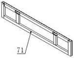
Fig. 5 is a schematic structural view of the end wall of the present invention.
The movable end side wall 7 comprises end walls 71, side walls 72, locking pins 73, pin shafts 74 and connecting plates 75, wherein the number of the side walls 72 is 12, and the lower parts of the side walls are provided with mounting columns and column inserting holes in the side beams 17 to mount the side walls 72 and the side beams 17.
FIG. 6 is a schematic view of the connection between the end wall and the side wall according to the present invention.
FIG. 7 is a schematic view of the separation of the end wall and the side wall according to the present invention.
One end of the connecting plate 75 is provided with a long hole and is connected with the end wall 71 through a pin shaft 74, and the other end of the connecting plate is provided with a square hook, and the size and the shape of the square hook are matched with the upper part of the side wall 72; the end wall 71 is connected with the side wall 72 through a connecting plate 75, and the end wall 71 can also be arranged at any longitudinal position of the vehicle body 1 to form a half-box half-flat-plate structure or a whole box structure, so that the use is more flexible; the end wall 71 and the side wall 72 adopt all-steel welding structures, are provided with assembling and disassembling holes and can be respectively interchanged. The connection by the connecting plate 75 prevents the end walls 71 and the side walls 72 from bulging outward when loaded with cargo.
Fig. 8 shows a schematic view of the mounting of the track panel support of the present invention.
The track panel support 8 is installed at two ends of the vehicle body 1, and is fastened through the twistlock lifting lock on the vehicle body 1, so that the position of the container lock can be properly adjusted and installed according to the distance between sleepers for loading the track panel 9.
Fig. 9 is a schematic view of the track panel support structure of the present invention.
The track panel support 8 comprises a supporting seat 81, guide columns 82 and connecting chains 83, the supporting seat 81 is provided with a plurality of mounting holes, and the guide columns 82 are mounted on the supporting seat 81 according to the minimum distance between the steel rails on the track panel and used for limiting the transverse displacement when the track panel is mounted, so that the dynamic limit is not exceeded; the guide post 82 is connected with the supporting seat 81 through a connecting chain 83, so that the guide post 82 is prevented from falling off accidentally when the vehicle runs empty; the connecting chain 83 may be a common rope.
Fig. 10 is a schematic structural view of the support base of the present invention.
Two ends of the guide column 82 are provided with inclined plates, so that the guide column can be conveniently inserted into the supporting seat 81 and the track panel falls; the guide column 821 is provided with a handle, so that the disassembly and the assembly are convenient.
Figure 11 shows a schematic view of the installation of the track panel of the present invention.
The two ends of the track panel are inserted into the track panel bracket 8 and placed on the vehicle body 1, and the fastening is realized through the rope fastening points and the fastening belts on the side beams 17.
The track panel bracket is provided with the mounting holes with different intervals, can adapt to the limiting function of track panels with different sizes, can utilize the line limitation to the maximum extent, reduce the height of a floor, load the number of the track panels to the maximum extent, and is convenient for an operator to mount and load the track panels as the upper part and the lower part of the guide column are of slope structures, thereby improving the working efficiency; the end wall and the side wall can be interchanged, and operation and maintenance are convenient. The invention can meet the running requirements of the subway and the national railway at the same time.
The above-described embodiments of the invention are intended to be illustrative only and are not intended to be limiting, as all changes that come within the scope of or equivalence to the invention are intended to be embraced therein.
Claims (7)
1. The utility model provides a multi-functional flatcar of railway which characterized in that: the device comprises a vehicle body (1), bogies (2), a braking device (3), a container locking device (4), vehicle body accessories (5), a coupler buffer device (6), a movable end side wall (7) and a track panel support (8), wherein the container locking device (4) is welded on the vehicle body (1), the braking device (3) is installed at the lower part of the vehicle body (1), the vehicle body accessories (5) are installed at the end part and two sides of the vehicle body (1), the coupler buffer device (6) is installed at two sides of the end part of the vehicle body (1), and the two bogies (2) are respectively installed at two ends of the lower part of the vehicle body (1); the movable end side wall (7) and the track panel bracket (8) are arranged on the vehicle body (1) according to the specification of the loaded goods; the braking device (3) comprises a wind braking device and a hand braking device, the hand braking device is spiral and can be operated on two sides of the vehicle body (1), the wind braking adopts a braking system of UIC standard, and meanwhile, the system is additionally provided with modules which are suitable for different speed and deceleration requirements of subways and can simultaneously meet the requirements of the subways and state railway lines on braking performance;
four emergency brake valves are arranged at four corners of the vehicle and are used for emergency braking of the train under special conditions; the hand braking device is used on a national railway line, and meets the requirement of line parking gradient; the spring parking brake device is used in a subway line and limited by the fact that the hand brake device cannot be used in a tunnel space, and the spring parking brake device and the hand brake device are isolated from each other, so that misoperation is avoided.
2. The railway utility platform wagon of claim 1, wherein: the vehicle body (1) is of an all-steel welded structure and comprises an end beam (11), a traction beam (12), a sleeper beam (13), a middle beam (14), a small cross beam (15), a support beam (16), side beams (17) and a large cross beam (18), wherein the middle beam (14) is of a fish belly type structure, the sleeper beam (13) and the cross beam (11) are of a variable-section double-web box type structure, and the side beams (17) are hot-rolled channel steel and are provided with rope bolt points; the anti-skid bicycle is characterized in that a floor (19) is paved on the bicycle body (1), and anti-skid pattern steel running plates (20) are installed at two ends of the bicycle body (1).
3. The railway utility platform car of claim 2, wherein: the bogie (2) is arranged at the lower part of the sleeper beam (13) and is connected with the vehicle body (1) through a center plate; the bogie (2) is provided with a vertical shock absorber and is a welded bogie; each bogie (2) is controlled by a separate relay valve and brake cylinder, enabling precise control of the braking force.
4. The railway utility platform car of claim 2, wherein: the container locking device (4) adopts a twistlock lifting lock, is provided with sixteen parts, and is respectively welded with the side beam (17) and the floor (19).
5. The railway utility platform car of claim 2, wherein: the car coupler buffering device (6) comprises an automatic vertical head car coupler and side buffers, the automatic vertical head car coupler is arranged on a traction beam (12), and the side buffers are arranged on two sides of an end beam (11); when the coupler is connected with the UIC railway freight car, the vertical coupler can be folded, and the side buffer acts; when the train is marshalled with a subway train, a vertical head coupler is adopted for coupling.
6. The railway utility platform car of claim 2, wherein: the movable end side wall (7) comprises end walls (71), side walls (72), locking pins (73), pin shafts (74) and connecting plates (75), the number of the side walls (72) is 12, and mounting columns are arranged at the lower parts of the side walls (72) and are in plug-in holes in the side beams (17) to mount the side walls (72) and the side beams (17); one end of the connecting plate (75) is provided with a long hole and is connected with the end wall (71) through a pin shaft (74), and the other end of the connecting plate is provided with a square hook, and the size and the shape of the square hook are matched with the upper part of the side wall (72); the end wall (71) is connected with the side wall (72) through a connecting plate (75), and the end wall (71) is arranged at any longitudinal position of the vehicle body (1) to form a half-box half-flat-plate structure or a whole box structure; the end wall (71) and the side wall (72) adopt all-steel welding structures, are provided with assembling and disassembling holes and can be interchanged respectively.
7. The railway multi-purpose flat car according to any one of claims 1 to 6, wherein: the track panel support (8) comprises a supporting seat (81), guide columns (82) and a connecting chain (83), the supporting seat (81) is provided with a plurality of mounting holes, the guide columns (82) are mounted on the supporting seat (81) according to the minimum distance between the steel rails on the track panel, and the guide columns (82) are connected with the supporting seat (81) through the connecting chain (83); the two ends of the guide post (82) are provided with inclined plates, so that the guide post can be conveniently inserted into the supporting seat (81) and the track panel falls into the supporting seat; the track panel supports (8) are installed at two ends of the vehicle body (1) and are fastened through a twistlock lifting lock on the vehicle body (1); the two ends of the track panel are inserted into the track panel bracket (8) and placed on the vehicle body (1), and the fastening is realized through the rope fastening points and the fastening belts on the side beams (17).
Priority Applications (1)
| Application Number | Priority Date | Filing Date | Title |
|---|---|---|---|
| CN201811444844.XA CN109664903B (en) | 2018-11-29 | 2018-11-29 | Multifunctional railway flatcar |
Applications Claiming Priority (1)
| Application Number | Priority Date | Filing Date | Title |
|---|---|---|---|
| CN201811444844.XA CN109664903B (en) | 2018-11-29 | 2018-11-29 | Multifunctional railway flatcar |
Publications (2)
| Publication Number | Publication Date |
|---|---|
| CN109664903A CN109664903A (en) | 2019-04-23 |
| CN109664903B true CN109664903B (en) | 2020-06-30 |
Family
ID=66143480
Family Applications (1)
| Application Number | Title | Priority Date | Filing Date |
|---|---|---|---|
| CN201811444844.XA Active CN109664903B (en) | 2018-11-29 | 2018-11-29 | Multifunctional railway flatcar |
Country Status (1)
| Country | Link |
|---|---|
| CN (1) | CN109664903B (en) |
Cited By (1)
| Publication number | Priority date | Publication date | Assignee | Title |
|---|---|---|---|---|
| RU222929U1 (en) * | 2023-10-26 | 2024-01-24 | Акционерное общество "ЕВРАЗ Нижнетагильский металлургический комбинат" | PLATFORM CAR FOR TRANSPORTATION OF LONG CARGO AND CONTAINERS |
Families Citing this family (4)
| Publication number | Priority date | Publication date | Assignee | Title |
|---|---|---|---|---|
| CN110386157A (en) * | 2019-07-18 | 2019-10-29 | 中车山东机车车辆有限公司 | The dismountable movable end side wall of articulated car |
| CN110667609B (en) * | 2019-10-14 | 2020-10-30 | 中车山东机车车辆有限公司 | Multi-gauge track panel support of railway flat car and railway flat car |
| CN110843821B (en) * | 2019-11-21 | 2020-09-01 | 中车山东机车车辆有限公司 | Multifunctional railway flatcar body device |
| CN110884508B (en) * | 2019-12-06 | 2020-12-01 | 中车山东机车车辆有限公司 | Multifunctional flatcar body |
Citations (13)
| Publication number | Priority date | Publication date | Assignee | Title |
|---|---|---|---|---|
| CN200992200Y (en) * | 2006-08-07 | 2007-12-19 | 中国南车集团眉山车辆厂 | Meter-gauge flat-car |
| RU2329906C2 (en) * | 2006-03-31 | 2008-07-27 | Общество С Ограниченной Ответственностью "Головное Специализированное Конструкторское Бюро Вагоностроения" | Car-platform |
| CN201633731U (en) * | 2010-04-14 | 2010-11-17 | 南车眉山车辆有限公司 | Broad-gauge multifunction container flat car |
| CN201745581U (en) * | 2010-07-20 | 2011-02-16 | 济南轨道交通装备有限责任公司 | Railway multi-purpose depressed center flat car |
| CN202624218U (en) * | 2012-05-21 | 2012-12-26 | 南车眉山车辆有限公司 | Narrow-rail multi-purpose flatcar |
| CN204055786U (en) * | 2014-07-23 | 2014-12-31 | 南车眉山车辆有限公司 | A kind of Flat car special for railway container |
| CN204264149U (en) * | 2014-09-28 | 2015-04-15 | 南车长江车辆有限公司 | A kind of novel articulated car structure |
| CN204659484U (en) * | 2015-06-15 | 2015-09-23 | 宝鸡南车时代工程机械有限公司 | Subway contact-net paying-out operation vehicle |
| CN206351686U (en) * | 2016-12-07 | 2017-07-25 | 中车山东机车车辆有限公司 | A kind of articulated car side wall device |
| CN107010080A (en) * | 2017-05-16 | 2017-08-04 | 中车眉山车辆有限公司 | A kind of many combination of sets vanning flat car for transportations |
| CN206552039U (en) * | 2017-02-23 | 2017-10-13 | 中车太原机车车辆有限公司 | A kind of long underframe railway container flat car |
| RU177592U1 (en) * | 2016-11-14 | 2018-03-01 | Акционерное Общество "Научно-Внедренческий Центр "Вагоны" | Platform wagon with swap body |
| CN208055773U (en) * | 2018-03-27 | 2018-11-06 | 中车山东机车车辆有限公司 | A kind of articulated car section of track holder |
-
2018
- 2018-11-29 CN CN201811444844.XA patent/CN109664903B/en active Active
Patent Citations (13)
| Publication number | Priority date | Publication date | Assignee | Title |
|---|---|---|---|---|
| RU2329906C2 (en) * | 2006-03-31 | 2008-07-27 | Общество С Ограниченной Ответственностью "Головное Специализированное Конструкторское Бюро Вагоностроения" | Car-platform |
| CN200992200Y (en) * | 2006-08-07 | 2007-12-19 | 中国南车集团眉山车辆厂 | Meter-gauge flat-car |
| CN201633731U (en) * | 2010-04-14 | 2010-11-17 | 南车眉山车辆有限公司 | Broad-gauge multifunction container flat car |
| CN201745581U (en) * | 2010-07-20 | 2011-02-16 | 济南轨道交通装备有限责任公司 | Railway multi-purpose depressed center flat car |
| CN202624218U (en) * | 2012-05-21 | 2012-12-26 | 南车眉山车辆有限公司 | Narrow-rail multi-purpose flatcar |
| CN204055786U (en) * | 2014-07-23 | 2014-12-31 | 南车眉山车辆有限公司 | A kind of Flat car special for railway container |
| CN204264149U (en) * | 2014-09-28 | 2015-04-15 | 南车长江车辆有限公司 | A kind of novel articulated car structure |
| CN204659484U (en) * | 2015-06-15 | 2015-09-23 | 宝鸡南车时代工程机械有限公司 | Subway contact-net paying-out operation vehicle |
| RU177592U1 (en) * | 2016-11-14 | 2018-03-01 | Акционерное Общество "Научно-Внедренческий Центр "Вагоны" | Platform wagon with swap body |
| CN206351686U (en) * | 2016-12-07 | 2017-07-25 | 中车山东机车车辆有限公司 | A kind of articulated car side wall device |
| CN206552039U (en) * | 2017-02-23 | 2017-10-13 | 中车太原机车车辆有限公司 | A kind of long underframe railway container flat car |
| CN107010080A (en) * | 2017-05-16 | 2017-08-04 | 中车眉山车辆有限公司 | A kind of many combination of sets vanning flat car for transportations |
| CN208055773U (en) * | 2018-03-27 | 2018-11-06 | 中车山东机车车辆有限公司 | A kind of articulated car section of track holder |
Cited By (2)
| Publication number | Priority date | Publication date | Assignee | Title |
|---|---|---|---|---|
| RU222929U1 (en) * | 2023-10-26 | 2024-01-24 | Акционерное общество "ЕВРАЗ Нижнетагильский металлургический комбинат" | PLATFORM CAR FOR TRANSPORTATION OF LONG CARGO AND CONTAINERS |
| RU223927U1 (en) * | 2023-11-22 | 2024-03-07 | Акционерное общество "ЕВРАЗ Нижнетагильский металлургический комбинат" | RAILWAY PLATFORM |
Also Published As
| Publication number | Publication date |
|---|---|
| CN109664903A (en) | 2019-04-23 |
Similar Documents
| Publication | Publication Date | Title |
|---|---|---|
| CN109664903B (en) | Multifunctional railway flatcar | |
| US4756256A (en) | Aerodynamic drag reduction for railcars | |
| US4665834A (en) | Apparatus for intermodal transport of highway containers | |
| CN100448716C (en) | Special device for transporting superlong steel rail and its transportation scheme | |
| US8997657B2 (en) | Ballast load device and method | |
| US5074725A (en) | Well car trailer adaptor | |
| US3028023A (en) | System of handling freight | |
| CN111452812A (en) | Long steel rail transport operation vehicle set | |
| CN2933959Y (en) | Special device for transporting ultra-long steel rail | |
| CN103909942B (en) | A kind of lightweight type Ore Transportation special gondola | |
| US3752083A (en) | Locomotive bogie having lifting dogs | |
| WO2021093092A1 (en) | Train maintenance vehicle suitable for air rail transit system | |
| CN201971015U (en) | Hopper open wagon | |
| CN110450796A (en) | It is a kind of to transport U-shaped or box-shaped precast beam rail transporter group | |
| CN200954820Y (en) | Moveable boxwagon | |
| CN203612013U (en) | Central traction device for large-axle-load bogie | |
| CN113581225A (en) | Large-load light-weight container flat car body and flat car comprising same | |
| CN209409726U (en) | A kind of highway railway combined transport cargo | |
| CN87208511U (en) | Railway lowbase flat wagon | |
| CN202686366U (en) | Railway truck special for transporting steel coils and ores | |
| CN113879350B (en) | Male and rail intermodal transportation system and railway transportation vehicle | |
| CN102092396B (en) | Mixed steel and wood floor for railway flatcars | |
| CN111877173A (en) | Long-distance rapid transition method for bridge girder erection machine | |
| CN2388085Y (en) | Gravity vehicle sliding-preventing device for railway arrival-advance track | |
| CN109398003A (en) | A kind of highway railway combined transport cargo |
Legal Events
| Date | Code | Title | Description |
|---|---|---|---|
| PB01 | Publication | ||
| PB01 | Publication | ||
| SE01 | Entry into force of request for substantive examination | ||
| SE01 | Entry into force of request for substantive examination | ||
| GR01 | Patent grant | ||
| GR01 | Patent grant |