CN109644829B - Intelligent agricultural irrigation system - Google Patents
Intelligent agricultural irrigation system Download PDFInfo
- Publication number
- CN109644829B CN109644829B CN201811546030.7A CN201811546030A CN109644829B CN 109644829 B CN109644829 B CN 109644829B CN 201811546030 A CN201811546030 A CN 201811546030A CN 109644829 B CN109644829 B CN 109644829B
- Authority
- CN
- China
- Prior art keywords
- fixedly connected
- cylinder body
- fixed
- mixing
- rod
- Prior art date
- Legal status (The legal status is an assumption and is not a legal conclusion. Google has not performed a legal analysis and makes no representation as to the accuracy of the status listed.)
- Expired - Fee Related
Links
Images


Classifications
-
- A—HUMAN NECESSITIES
- A01—AGRICULTURE; FORESTRY; ANIMAL HUSBANDRY; HUNTING; TRAPPING; FISHING
- A01G—HORTICULTURE; CULTIVATION OF VEGETABLES, FLOWERS, RICE, FRUIT, VINES, HOPS OR SEAWEED; FORESTRY; WATERING
- A01G25/00—Watering gardens, fields, sports grounds or the like
- A01G25/02—Watering arrangements located above the soil which make use of perforated pipe-lines or pipe-lines with dispensing fittings, e.g. for drip irrigation
-
- A—HUMAN NECESSITIES
- A01—AGRICULTURE; FORESTRY; ANIMAL HUSBANDRY; HUNTING; TRAPPING; FISHING
- A01C—PLANTING; SOWING; FERTILISING
- A01C23/00—Distributing devices specially adapted for liquid manure or other fertilising liquid, including ammonia, e.g. transport tanks or sprinkling wagons
- A01C23/001—Sludge spreaders, e.g. liquid manure spreaders
- A01C23/002—Sludge spreaders, e.g. liquid manure spreaders provided with auxiliary arrangements, e.g. pumps, agitators, cutters
-
- A—HUMAN NECESSITIES
- A01—AGRICULTURE; FORESTRY; ANIMAL HUSBANDRY; HUNTING; TRAPPING; FISHING
- A01C—PLANTING; SOWING; FERTILISING
- A01C23/00—Distributing devices specially adapted for liquid manure or other fertilising liquid, including ammonia, e.g. transport tanks or sprinkling wagons
- A01C23/007—Metering or regulating systems
-
- A—HUMAN NECESSITIES
- A01—AGRICULTURE; FORESTRY; ANIMAL HUSBANDRY; HUNTING; TRAPPING; FISHING
- A01C—PLANTING; SOWING; FERTILISING
- A01C23/00—Distributing devices specially adapted for liquid manure or other fertilising liquid, including ammonia, e.g. transport tanks or sprinkling wagons
- A01C23/04—Distributing under pressure; Distributing mud; Adaptation of watering systems for fertilising-liquids
- A01C23/047—Spraying of liquid fertilisers
-
- A—HUMAN NECESSITIES
- A01—AGRICULTURE; FORESTRY; ANIMAL HUSBANDRY; HUNTING; TRAPPING; FISHING
- A01G—HORTICULTURE; CULTIVATION OF VEGETABLES, FLOWERS, RICE, FRUIT, VINES, HOPS OR SEAWEED; FORESTRY; WATERING
- A01G25/00—Watering gardens, fields, sports grounds or the like
- A01G25/02—Watering arrangements located above the soil which make use of perforated pipe-lines or pipe-lines with dispensing fittings, e.g. for drip irrigation
- A01G25/023—Dispensing fittings for drip irrigation, e.g. drippers
-
- A—HUMAN NECESSITIES
- A01—AGRICULTURE; FORESTRY; ANIMAL HUSBANDRY; HUNTING; TRAPPING; FISHING
- A01G—HORTICULTURE; CULTIVATION OF VEGETABLES, FLOWERS, RICE, FRUIT, VINES, HOPS OR SEAWEED; FORESTRY; WATERING
- A01G25/00—Watering gardens, fields, sports grounds or the like
- A01G25/16—Control of watering
-
- A—HUMAN NECESSITIES
- A01—AGRICULTURE; FORESTRY; ANIMAL HUSBANDRY; HUNTING; TRAPPING; FISHING
- A01M—CATCHING, TRAPPING OR SCARING OF ANIMALS; APPARATUS FOR THE DESTRUCTION OF NOXIOUS ANIMALS OR NOXIOUS PLANTS
- A01M7/00—Special adaptations or arrangements of liquid-spraying apparatus for purposes covered by this subclass
- A01M7/0025—Mechanical sprayers
- A01M7/0032—Pressure sprayers
- A01M7/0042—Field sprayers, e.g. self-propelled, drawn or tractor-mounted
-
- A—HUMAN NECESSITIES
- A01—AGRICULTURE; FORESTRY; ANIMAL HUSBANDRY; HUNTING; TRAPPING; FISHING
- A01M—CATCHING, TRAPPING OR SCARING OF ANIMALS; APPARATUS FOR THE DESTRUCTION OF NOXIOUS ANIMALS OR NOXIOUS PLANTS
- A01M7/00—Special adaptations or arrangements of liquid-spraying apparatus for purposes covered by this subclass
- A01M7/005—Special arrangements or adaptations of the spraying or distributing parts, e.g. adaptations or mounting of the spray booms, mounting of the nozzles, protection shields
-
- A—HUMAN NECESSITIES
- A01—AGRICULTURE; FORESTRY; ANIMAL HUSBANDRY; HUNTING; TRAPPING; FISHING
- A01M—CATCHING, TRAPPING OR SCARING OF ANIMALS; APPARATUS FOR THE DESTRUCTION OF NOXIOUS ANIMALS OR NOXIOUS PLANTS
- A01M7/00—Special adaptations or arrangements of liquid-spraying apparatus for purposes covered by this subclass
- A01M7/0089—Regulating or controlling systems
-
- B—PERFORMING OPERATIONS; TRANSPORTING
- B01—PHYSICAL OR CHEMICAL PROCESSES OR APPARATUS IN GENERAL
- B01F—MIXING, e.g. DISSOLVING, EMULSIFYING OR DISPERSING
- B01F27/00—Mixers with rotary stirring devices in fixed receptacles; Kneaders
- B01F27/80—Mixers with rotary stirring devices in fixed receptacles; Kneaders with stirrers rotating about a substantially vertical axis
- B01F27/90—Mixers with rotary stirring devices in fixed receptacles; Kneaders with stirrers rotating about a substantially vertical axis with paddles or arms
- B01F27/902—Mixers with rotary stirring devices in fixed receptacles; Kneaders with stirrers rotating about a substantially vertical axis with paddles or arms cooperating with intermeshing elements fixed on the receptacle walls
-
- F—MECHANICAL ENGINEERING; LIGHTING; HEATING; WEAPONS; BLASTING
- F03—MACHINES OR ENGINES FOR LIQUIDS; WIND, SPRING, OR WEIGHT MOTORS; PRODUCING MECHANICAL POWER OR A REACTIVE PROPULSIVE THRUST, NOT OTHERWISE PROVIDED FOR
- F03B—MACHINES OR ENGINES FOR LIQUIDS
- F03B13/00—Adaptations of machines or engines for special use; Combinations of machines or engines with driving or driven apparatus; Power stations or aggregates
-
- Y—GENERAL TAGGING OF NEW TECHNOLOGICAL DEVELOPMENTS; GENERAL TAGGING OF CROSS-SECTIONAL TECHNOLOGIES SPANNING OVER SEVERAL SECTIONS OF THE IPC; TECHNICAL SUBJECTS COVERED BY FORMER USPC CROSS-REFERENCE ART COLLECTIONS [XRACs] AND DIGESTS
- Y02—TECHNOLOGIES OR APPLICATIONS FOR MITIGATION OR ADAPTATION AGAINST CLIMATE CHANGE
- Y02P—CLIMATE CHANGE MITIGATION TECHNOLOGIES IN THE PRODUCTION OR PROCESSING OF GOODS
- Y02P70/00—Climate change mitigation technologies in the production process for final industrial or consumer products
- Y02P70/10—Greenhouse gas [GHG] capture, material saving, heat recovery or other energy efficient measures, e.g. motor control, characterised by manufacturing processes, e.g. for rolling metal or metal working
Abstract
The invention discloses an intelligent agricultural irrigation system, which comprises a pretreatment device and a rotary joint pretreatment device, wherein the pretreatment device comprises a water treatment device and a feeding device, a mixing cavity is arranged in a first cylinder body of the water treatment device, the mixing cavity is communicated with the feeding device, a water outlet of the first cylinder body is connected with the rotary joint, the water treatment device is fixed on a bearing plate on the upper side of a lifting frame, water flows back to the mixing cavity at a backflow port, a movable blade of an impact mixing supercharging mechanism rotates, quantitative pesticide or chemical fertilizer is controlled by the feeding device to enter the mixing cavity through a mixed flow port, the pesticide or chemical fertilizer is mixed and supercharged by the mixing supercharging mechanism and then enters the rotary joint, an impact turbine fan drives the rotary joint to rotate, and mixed liquid is sprayed out through an atomizing nozzle without additionally providing energy, the system is energy-saving and environment-friendly, has the functions of pesticide spraying and fertilizer application during irrigation, and, moreover, the functions are various, and the labor is saved.
Description
Technical Field
The invention belongs to the technical field of agricultural irrigation, and particularly relates to an intelligent agricultural irrigation system.
Background
At present, agricultural irrigation generally adopts a traditional irrigation method, the traditional irrigation method is that the agricultural irrigation enters the field from the ground surface and infiltrates soil by virtue of gravity and capillary action, so the method is also called as gravity irrigation method, and the method is the oldest and the most widely and mainly applied irrigation method at present; according to different soil wetting modes, the method can be divided into furrow irrigation, flood irrigation and flood irrigation; although the traditional irrigation method is simple, the water waste is large and the cost is high.
Along with the development of modern irrigation technology, the method of water-saving irrigation is gradually popularized, the modern irrigation technology can not only effectively utilize limited water resources and relieve the severe situation of excessive underground water exploitation and crust sinking, but also importantly, the growth conditions of crops, fruit trees and the like can be improved through organic combination with fertilization, the yield per unit and the fruit quality are improved, and good social benefit and economic benefit are achieved; however, although the traditional water-saving irrigation has the functions of pesticide application and fertilizer application, the pesticide and fertilizer are wasted due to the fact that accurate control cannot be achieved, and meanwhile, the redundant pesticide and fertilizer seriously pollute the environment, so that the economical efficiency is poor, and the cost is high.
Disclosure of Invention
The invention aims to provide an intelligent agricultural irrigation system to solve the problems in the background art.
In order to solve the above problems, the present invention provides a technical solution: an intelligent agricultural irrigation system comprises a pretreatment device and a rotary joint, wherein the pretreatment device comprises a water treatment device and a feeding device, the water treatment device comprises a first cylinder body, a water outlet is communicated with a mixing cavity in the first cylinder body, the bottom side of the mixing cavity is a circular backflow port with an expanded lower side, the backflow port is concentric with the lower end of a first water inlet in an L shape, the upper end of the first water inlet penetrates through the first cylinder body, the upper side surface of the first water inlet is fixedly connected with the first cylinder body, a gap is formed between the lower end of the first water inlet and the side wall of a second cylinder body of the feeding device, the side surface of the backflow port is fixedly connected with the inner side wall of the first cylinder body, the outer side surface of the backflow port is fixedly connected with the upper side surface of the second cylinder body, a mixed flow port in the upper side surface of the second cylinder body is communicated with the backflow port, and the left lower side surface of the mixed, the cavity left end and the second water inlet are communicated and fixedly connected, the through hole is in contact connection with the left side of the plugging gasket, the right side of the plugging gasket is fixedly connected with one end of a sliding rod, the sliding rod penetrates through a first sliding block and is in sliding connection with the first sliding block, the other end of the sliding rod is fixedly connected with a first piston, the first sliding block is fixedly connected with the inner side wall of a second cylinder, the first piston is elastically connected with a second piston on the right side through a spring, the second piston is fixedly connected with one end of a telescopic rod, and the other end of the telescopic rod is fixedly connected with the right side wall of the second cylinder.
The rotary joint comprises an L-shaped joint, a rotating shaft, a connecting pipe and a connecting ring pipe, wherein the upper end of the L-shaped joint is transversely connected with the atomizing spray head in a threaded fixed mode, a first clamping ring and a second clamping ring are arranged on the inner side wall of the outlet at the lower end of the L-shaped joint, the first clamping ring and the second clamping ring are matched with a convex ring at the upper end of the connecting pipe in a sealing and rotating mode, a third clamping ring is arranged at the lower end of the connecting pipe, a fourth clamping ring is arranged at the upper end of the connecting ring pipe, the third clamping ring is in contact fixed connection with the fourth clamping ring, and the connecting ring pipe is.
Second cylinder downside and the bearing plate fixed connection of base, the base includes dead lever, crane, bearing plate and mount pad, the mount pad is square structure, and the four-end angle all is equipped with the fixed orifices passes through the first part screw thread in dead lever side and dead lever threaded connection, be equipped with two cranes behind the side front both sides on the mount pad, the crane is articulated with first fixed block, second fixed block, third fixed block and second slider respectively and is connected, first fixed block and hydraulic telescoping rod top fixed connection, hydraulic telescoping rod and mount pad fixed connection, second fixed block and mount pad fixed connection, third fixed block and bearing plate fixed connection, the spout sliding connection of second slider and bearing plate downside right-hand member.
Preferably, the method comprises the following steps: be equipped with mixed booster mechanism in the mixing chamber, mixed booster mechanism includes rotary drum, movable vane and fixed vane, the rotary drum rotates with the lateral wall that penetrates the inside first water inlet of first cylinder body 10 to be connected, movable vane one end and rotary drum fixed connection, the rotary drum side is equipped with four rows of annular evenly distributed's movable vane, and the figure by supreme every row of movable vane in proper order down is eight, ten, twelve and fourteen in proper order, and the distance equals between every row of movable vane, all is equipped with one row of fixed vane between every two rows of movable vane, fixed vane keeps away from rotary drum one end and mixing chamber inner wall fixed connection, fixed vane annular evenly distributed, and by supreme number of every row of fixed vane in proper order down is nine, eleven and thirteen.
Preferably, the method comprises the following steps: the side is equipped with the lug on the L shape connects, pivot upper end and lug fixed connection, just the pivot is concentric with the connecting pipe, the pivot is located the connecting pipe part and is equipped with three turbine fan, three turbine fan evenly distributed.
Preferably, the method comprises the following steps: the fixed rod comprises a vertical rod, a thread, a stop block, a drilling cone, a spiral blade and a handle; the utility model discloses a drilling tool, including montant, drill point, screw thread, dog, montant lateral wall, montant upper end and the handle fixed connection that has anti-skidding line, montant lower extreme and drill cone fixed connection, montant side middle part is equipped with the dog, the montant lateral wall of dog upside is equipped with the screw thread, the montant lateral wall of dog downside is equipped with the spiral blade.
Preferably, the method comprises the following steps: the diameter of the plugging gasket is larger than that of the through hole, and the plugging gasket is used for sealing the through hole.
The invention has the beneficial effects that: the power source of the mixed supercharging mechanism is water flow energy, the mixed supercharging mechanism supercharges mixed liquid while mixing water and pesticide or water and chemical fertilizer, the mixed supercharged mixed liquid impacts a turbine fan to drive a rotary joint to rotate, and the mixed liquid is sprayed out through an atomizing nozzle, so that extra energy is not required to be provided in the whole working process, the energy-saving and environment-friendly irrigation system is energy-saving and environment-friendly, has the functions of pesticide spraying and fertilizer application while irrigation, improves the utilization rate of irrigation water, has various functions and saves manpower; through loading attachment, realize the regulation and control to pesticide, chemical fertilizer volume, when guaranteeing maximize performance pesticide, chemical fertilizer efficiency, saved the administrative cost who beats pesticide, fertilize, consequently irrigation system's intellectuality, not only more environmental protection will irrigate moreover and beat the pesticide and combine to have considerable economic benefits with the fertilization.
Drawings
For ease of illustration, the invention is described in detail by the following detailed description and the accompanying drawings;
FIG. 1 is a block diagram of the present invention;
FIG. 2 is a view of the swivel joint of the present invention;
FIG. 3 is a diagram of the pretreatment structure of the present invention;
FIG. 4 is a view of the mixing mechanism within the mixing chamber of the present invention;
FIG. 5 is an enlarged view of a portion of the invention A;
FIG. 6 is a view of the base structure of the present invention;
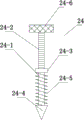
fig. 7 is a structure diagram of the fixing rod of the present invention.
Reference numerals in the figures
1. A base; 2. a water treatment device; 3. a feeding device; 4. a rotary joint; 5. an atomizing spray head; 6. an L-shaped joint; 6-1, bumps; 6-2, a first snap ring; 6-3, a second snap ring; 7. a rotating shaft; 7-1, a turbine fan; 8. a connecting pipe; 8-1, a convex ring; 8-2, a third snap ring; 9. connecting a ring pipe; 9-1 and a fourth snap ring; 10. a first cylinder; 11. a second cylinder; 11-1, a mixed flow port; 12. a water outlet; 13. a first water inlet; 13-1, a reflux port; 14. a mixing chamber; 14-1, a rotating drum; 14-2, movable blades; 14-3, fixing the blades; 15. a second water inlet; 16. a cavity; 16-1, a through hole; 17. plugging the gasket; 18. a slide bar; 19. a first slider; 20. a first piston; 21. a spring; 22. a second piston; 23. a telescopic rod; 24. fixing the rod; 24-1, a vertical rod; 24-2, threads; 24-3, a stop block; 24-4, drilling a hole; 24-5, a helical blade; 24-6, a handle; 25. a lifting frame; 26. a bearing plate; 27. a mounting seat; 27-1, fixing holes; 28. a hydraulic telescopic rod; 29. a first fixed block; 30. a second fixed block; 31. a third fixed block; 32. a second slider; 33. a chute.
Detailed Description
As shown in fig. 1 to 7, the following technical solutions are adopted in the present embodiment: an intelligent agricultural irrigation system comprises a pretreatment device and a rotary joint 4, wherein the pretreatment device comprises a water treatment device 2 and a feeding device 3, the water treatment device 2 comprises a first cylinder 10, a water outlet 12 penetrates through a mixing cavity 14 inside the first cylinder 10, the bottom side of the mixing cavity 14 is a circular backflow port 13-1 with an expanded lower side, the backflow port 13-1 is concentric with the lower end of a first water inlet 13 in an L shape, the upper end of the first water inlet 13 penetrates through the first cylinder 10, the first water inlet 13 is fixedly connected with the upper side surface of the first cylinder 10, a gap is formed between the lower end of the first water inlet 13 and the side wall of a second cylinder 11 of the feeding device 3, the side surface of the backflow port 13-1 is fixedly connected with the inner side wall of the first cylinder 10, the outer edge of the lower side surface of the backflow port 13-1 is fixedly connected with the upper side surface of the second cylinder 11, the mixing port 11-1 on the upper side surface of the second cylinder body 11 is communicated with the return port 13-1, the left lower side of the mixing port 11-1 is provided with a through hole 16-1 leading to the right end of the cavity 16, the left end of the cavity 16 is fixedly connected with the second water inlet 15 in a penetrating way, the through hole 16-1 is connected with the left side of the blocking gasket 17 in a contacting way, the right side of the plugging pad 17 is fixedly connected with one end of a sliding rod 18, the sliding rod 18 penetrates through a first sliding block 19, the slide bar 18 is connected with the first slide block 19 in a sliding way, the other end of the slide bar 18 is fixedly connected with the first piston 20, the first slide block 19 is fixedly connected with the inner side wall of the second cylinder 11, the first piston 20 is elastically connected with the second piston 22 on the right side through a spring 21, the second piston is fixedly connected with one end of a telescopic rod 23, and the other end of the telescopic rod 23 is fixedly connected with the right side wall of the second cylinder body 11.
The rotary joint 4 comprises an L-shaped joint 6, a rotating shaft 7, a connecting pipe 8 and a connecting ring pipe 9, wherein a transverse outlet at the upper end of the L-shaped joint 6 is fixedly connected with an atomizing nozzle 5 through threads, a first clamping ring 6-2 and a second clamping ring 6-3 are arranged on the inner side wall of an outlet at the lower end of the L-shaped joint 6, the first clamping ring 6-2 and the second clamping ring 6-3 are matched with a convex ring 8-1 at the upper end of the connecting pipe 8 to be in sealing and rotating connection, a third clamping ring 8-2 is arranged at the lower end of the connecting pipe 8, a fourth clamping ring 9-1 is arranged at the upper end of the connecting ring pipe 9, the third clamping ring 8-2 is fixedly connected with the fourth clamping ring 9-1 in a contact manner, and the connecting ring pipe 9 is fixedly connected.
The lower side surface of the second cylinder body 11 is fixedly connected with a bearing plate 26 of the base 1, the base 1 comprises a fixing rod 24, a lifting frame 25, the bearing plate 26 and a mounting seat 27, the mounting seat 27 is of a square structure, and the four corners are all provided with fixing holes 27-1. the fixing holes 27-1 are in threaded connection with the fixing rod 24 through the threads 24-2 of the upper half part of the side surface of the fixing rod 24, two lifting frames 25 are arranged at the front and the back of the front side of the upper side of the mounting seat 27, the lifting frames 25 are respectively hinged with a first fixed block 29, a second fixed block 30, a third fixed block 31 and a second sliding block 32, the first fixed block 29 is fixedly connected with the top end of the hydraulic telescopic rod 28, the hydraulic telescopic rod 28 is fixedly connected with the mounting seat 27, the second fixed block 30 is fixedly connected with the mounting seat 27, the third fixed block 31 is fixedly connected with the bearing plate 26, and the second sliding block 32 is slidably connected with a sliding groove 33 at the right end of the lower side of the bearing plate 26.
A mixing supercharging mechanism is arranged in the mixing cavity 14 and comprises a rotary drum 14-1, movable blades 14-2 and fixed blades 14-3, the rotary drum 14-1 is rotatably connected with the outer side wall of a first water inlet 13 penetrating into the first cylinder 10, one ends of the movable blades 14-2 are fixedly connected with the rotary drum 14-1, four rows of movable blades 14-2 which are uniformly distributed in an annular mode are arranged on the side face of the rotary drum 14-1, the number of each row of movable blades 14-2 is eight, ten, twelve and fourteen in sequence from bottom to top, the distance between each row of movable blades 14-2 is equal, a row of fixed blades 14-3 is arranged between each two rows of movable blades 14-2, one end, far away from the rotary drum 14-1, of each fixed blade 14-3 is fixedly connected with the inner side wall of the mixing cavity 14, the fixed blades 14-3 are uniformly distributed in an annular shape, and the number of each row of fixed blades 14-3 is nine, eleven and thirteen in turn from bottom to top.
The side of the L-shaped joint 6 is provided with a convex block 6-1, the upper end of the rotating shaft 7 is fixedly connected with the convex block 6-1, the rotating shaft 7 is concentric with the connecting pipe 8, the part of the rotating shaft 7, which is located at the connecting pipe 8, is provided with three turbine fans 7-1, and the three turbine fans 7-1 are uniformly distributed.
The fixing rod 24 comprises a vertical rod 24-1, a thread 24-2, a stop block 24-3, a drilling cone 24-4, a spiral blade 24-5 and a handle 24-6; the upper end of the vertical rod 24-1 is fixedly connected with a handle 24-6 with anti-skid lines, the lower end of the vertical rod 24-1 is fixedly connected with a drill cone 24-4, a stop block 24-3 is arranged in the middle of the side face of the vertical rod 24-1, threads 24-2 are arranged on the side wall of the vertical rod 24-1 on the upper side of the stop block 24-3, and a spiral blade 24-5 is arranged on the side wall of the vertical rod 24-1 on the lower side of the stop block 24-3.
The diameter of the plugging gasket 17 is larger than that of the through hole 16-1.
The working principle is as follows: rotating a handle 24-6, inserting a fixed rod 24 into the ground, fixing a base 1, when irrigating, water enters a mixing cavity 14 through a first water inlet 13, in the mixing cavity 14, water flow impacts a movable blade 14-2 of a mixing mechanism to rotate, sequentially passes through the movable blade 14-2 and a fixed blade 14-3 from bottom to top, water flow energy is converted into pressure, then the pressure enters a rotary joint 4, an impact turbine fan 7-1 drives an L-shaped joint 6 to rotate, meanwhile, water is sprayed out from an atomizing nozzle 5 to irrigate farmlands, when fertilizing is needed, a fertilizing pipe is connected into a second water inlet 15, fertilizer enters a cavity 16 and pushes a blocking gasket 17, and because the water suddenly flows back at a backflow port 13-1, the fertilizer and the water are fully mixed, further mixed by the turbine fan 7-1 and then sprayed out through the atomizing nozzle 5, when pesticide spraying is needed, the liquid medicine is connected to the second water inlet 15, the lifting frame 25 is pushed by the hydraulic telescopic rod 28 to rise to the position where the atomizing nozzle 5 exceeds the height of crops, and atomization and pesticide spraying are carried out; the telescopic rod 23 is used for adjusting the compression degree of the second piston 22 to adjust the compression degree of the spring 21, and further adjusting the force for pushing the plugging gasket 17, so that the purpose of adjusting the flow of pesticide or chemical fertilizer is achieved.
While there have been shown and described what are at present considered to be the fundamental principles of the invention and its essential features and advantages, it will be understood by those skilled in the art that the invention is not limited by the embodiments described above, which are merely illustrative of the principles of the invention, but that various changes and modifications may be made therein without departing from the spirit and scope of the invention as defined by the appended claims and their equivalents.
Claims (6)
1. An intelligent agricultural irrigation system, includes preprocessing device and rotary joint (4), its characterized in that: the pretreatment device comprises a water treatment device (2) and a feeding device (3), wherein the water treatment device (2) comprises a first cylinder body (10), a water outlet (12) penetrates through a mixing cavity (14) in the first cylinder body (10), the bottom side of the mixing cavity (14) is a circular backflow port (13-1) with the lower side expanded, the backflow port (13-1) is concentric with the lower end of a first L-shaped water inlet (13), the upper end of the first water inlet (13) penetrates through the first cylinder body (10), the first water inlet (13) is fixedly connected with the upper side face of the first cylinder body (10), a gap is formed between the lower end of the first water inlet (13) and the side wall of a second cylinder body (11) of the feeding device (3), the side face of the backflow port (13-1) is fixedly connected with the inner side wall of the first cylinder body (10), the outer side face of the backflow port (13-1) is fixedly connected with the upper side face of the second cylinder body (11), the mixing port (11-1) on the upper side surface of the second cylinder body (11) is communicated with the backflow port (13-1), the lower left side of the mixing port (11-1) is provided with a through hole (16-1) leading to the right end of a cavity (16), the left end of the cavity (16) is fixedly connected with a second water inlet (15) in a penetrating way, the through hole (16-1) is connected with the left side of a blocking gasket (17) in a contacting way, the right side of the blocking gasket (17) is fixedly connected with one end of a sliding rod (18), the sliding rod (18) penetrates through a first sliding block (19), the sliding rod (18) is connected with the first sliding block (19) in a sliding way, the other end of the sliding rod (18) is fixedly connected with a first piston (20), the first sliding block (19) is fixedly connected with the inner side wall of the second cylinder body (11), and the first piston (20) is elastically connected with a second piston (22) on the right side, the second piston is fixedly connected with one end of a telescopic rod (23), the other end of the telescopic rod (23) is fixedly connected with the right side wall of a second cylinder body (11), a mixing supercharging mechanism is arranged in the mixing cavity (14), the mixing supercharging mechanism comprises a rotary drum (14-1), movable blades (14-2) and fixed blades (14-3), the rotary drum (14-1) is rotatably connected with the outer side wall of a first water inlet (13) penetrating into the first cylinder body (10), one ends of the movable blades (14-2) are fixedly connected with the rotary drum (14-1), four rows of movable blades (14-2) which are uniformly distributed in an annular mode are arranged on the side face of the rotary drum (14-1), the number of each row of movable blades (14-2) is eight, ten, twelve and fourteen in sequence from bottom to top, and the distance between each row of movable blades (14-2) is equal, a row of fixed blades (14-3) are arranged between every two rows of movable blades (14-2), one end, far away from the rotating drum (14-1), of each fixed blade (14-3) is fixedly connected with the inner side wall of the mixing cavity (14), the fixed blades (14-3) are uniformly distributed in an annular mode, and the number of each row of fixed blades (14-3) is nine, eleven and thirteen in sequence from bottom to top.
2. The intelligent agricultural irrigation system of claim 1, wherein: the rotary joint (4) comprises an L-shaped joint (6), a rotating shaft (7), a connecting pipe (8) and a connecting ring pipe (9), the transverse outlet at the upper end of the L-shaped joint (6) is fixedly connected with the atomizing nozzle (5) through threads, a first snap ring (6-2) and a second snap ring (6-3) are arranged on the inner side wall of the outlet at the lower end of the L-shaped joint (6), the first snap ring (6-2) and the second snap ring (6-3) are matched with a convex ring (8-1) at the upper end of the connecting pipe (8) for sealing and rotating connection, a third snap ring (8-2) is arranged at the lower end of the connecting pipe (8), a fourth snap ring (9-1) is arranged at the upper end of the connecting ring pipe (9), the third snap ring (8-2) is fixedly connected with the fourth snap ring (9-1) in a contact manner, the connecting ring pipe (9) is fixedly connected with an L-shaped water outlet (12) on the right side of the first cylinder body (10) in a threaded manner.
3. The intelligent agricultural irrigation system of claim 1, wherein: the utility model discloses a hydraulic cylinder, including second cylinder body (11) downside and bearing plate (26) fixed connection of base (1), base (1) includes dead lever (24), crane (25), bearing plate (26) and mount pad (27), mount pad (27) are square structure, and the four-end angle all is equipped with fixed orifices (27-1) pass through screw thread (24-2) and dead lever (24) threaded connection of dead lever (24) side first half, be equipped with two crane (25) behind the side front both sides on mount pad (27), crane (25) articulate with first fixed block (29), second fixed block (30), third fixed block (31) and second slider (32) respectively and are connected, first fixed block (29) and hydraulic telescoping rod (28) top fixed connection, hydraulic telescoping rod (28) and mount pad (27) fixed connection, the second fixed block (30) is fixedly connected with the mounting seat (27), the third fixed block (31) is fixedly connected with the bearing plate (26), and the second sliding block (32) is slidably connected with a sliding groove (33) at the right end of the lower side of the bearing plate (26).
4. The intelligent agricultural irrigation system of claim 2, wherein: the side is equipped with lug (6-1) on L shape joint (6), pivot (7) upper end and lug (6-1) fixed connection, just pivot (7) are concentric with connecting pipe (8), pivot (7) are located connecting pipe (8) part and are equipped with three turbofan (7-1), three turbofan (7-1) evenly distributed.
5. The intelligent agricultural irrigation system of claim 3, wherein: the fixing rod (24) comprises a vertical rod (24-1), a thread (24-2), a stop block (24-3), a drilling cone (24-4), a spiral blade (24-5) and a handle (24-6); the anti-skidding drill bit is characterized in that the upper end of the vertical rod (24-1) is fixedly connected with a handle (24-6) with anti-skidding lines, the lower end of the vertical rod (24-1) is fixedly connected with a drill cone (24-4), a stop block (24-3) is arranged in the middle of the side face of the vertical rod (24-1), threads (24-2) are arranged on the side wall of the vertical rod (24-1) on the upper side of the stop block (24-3), and a spiral blade (24-5) is arranged on the side wall of the vertical rod (24-1) on the lower side of the stop block (24.
6. The intelligent agricultural irrigation system of claim 1, wherein: the diameter of the plugging gasket (17) is larger than that of the through hole (16-1).
Priority Applications (1)
| Application Number | Priority Date | Filing Date | Title |
|---|---|---|---|
| CN201811546030.7A CN109644829B (en) | 2018-12-18 | 2018-12-18 | Intelligent agricultural irrigation system |
Applications Claiming Priority (1)
| Application Number | Priority Date | Filing Date | Title |
|---|---|---|---|
| CN201811546030.7A CN109644829B (en) | 2018-12-18 | 2018-12-18 | Intelligent agricultural irrigation system |
Publications (2)
| Publication Number | Publication Date |
|---|---|
| CN109644829A CN109644829A (en) | 2019-04-19 |
| CN109644829B true CN109644829B (en) | 2020-12-01 |
Family
ID=66114868
Family Applications (1)
| Application Number | Title | Priority Date | Filing Date |
|---|---|---|---|
| CN201811546030.7A Expired - Fee Related CN109644829B (en) | 2018-12-18 | 2018-12-18 | Intelligent agricultural irrigation system |
Country Status (1)
| Country | Link |
|---|---|
| CN (1) | CN109644829B (en) |
Families Citing this family (4)
| Publication number | Priority date | Publication date | Assignee | Title |
|---|---|---|---|---|
| CN111264503A (en) * | 2020-03-19 | 2020-06-12 | 蒲军 | Automatic pesticide spraying device utilizing turbocharging |
| CN111911336A (en) * | 2020-07-08 | 2020-11-10 | 哈尔滨首捷智能科技有限公司 | Annular tidal energy permanent magnet generator |
| CN111955123A (en) * | 2020-08-12 | 2020-11-20 | 塔里木大学 | Proportional mixing variable control fertilization tank used in cotton drip irrigation |
| CN112655533B (en) * | 2020-12-10 | 2022-10-11 | 冯建波 | Irrigation equipment for afforestation engineering convenient to control rate of going out water |
Citations (12)
| Publication number | Priority date | Publication date | Assignee | Title |
|---|---|---|---|---|
| CN87215109U (en) * | 1987-11-27 | 1988-09-14 | 长沙铁路分局长沙车站 | Differential pressure auto water saving valve |
| US4971248A (en) * | 1989-06-01 | 1990-11-20 | Marino Frank A | Automatic lawn treatment device |
| US6533557B1 (en) * | 2000-08-11 | 2003-03-18 | David G. Williams | Positive displacement pump |
| CN101992038A (en) * | 2009-08-28 | 2011-03-30 | 陈黄传 | Spiral-flow sectional tube type liquid stirring device |
| CN203586203U (en) * | 2013-11-11 | 2014-05-07 | 广东美的厨房电器制造有限公司 | Premix burner and gas stove |
| CN105961145A (en) * | 2016-06-30 | 2016-09-28 | 余庆县惠农果蔬销售农民专业合作社 | Vegetable planting and irrigating device |
| CN205830642U (en) * | 2016-06-30 | 2016-12-28 | 余庆县惠农果蔬销售农民专业合作社 | Growing vegetables irrigation device |
| CN206212866U (en) * | 2016-11-28 | 2017-06-06 | 天津市武清区植保植检站 | A kind of water-fertilizer integral irrigation system |
| CN206530745U (en) * | 2016-12-12 | 2017-09-29 | 扬州大学 | A kind of anti-interference spring loaded safety valve of large-scale irrigation water delivery pipe network noresidue damping erosion control |
| CN206993948U (en) * | 2017-07-27 | 2018-02-13 | 严贞 | A kind of integral irrigation rig of agricultural water fertilizer |
| CN107980422A (en) * | 2017-12-20 | 2018-05-04 | 玉林市金腾建材有限公司 | A kind of architecture greening plant-climbing rack |
| CN207460963U (en) * | 2017-11-09 | 2018-06-08 | 昆明轿子雪山食品有限公司 | A kind of greenhouse for planting vegetable of water-fertilizer integral |
-
2018
- 2018-12-18 CN CN201811546030.7A patent/CN109644829B/en not_active Expired - Fee Related
Patent Citations (12)
| Publication number | Priority date | Publication date | Assignee | Title |
|---|---|---|---|---|
| CN87215109U (en) * | 1987-11-27 | 1988-09-14 | 长沙铁路分局长沙车站 | Differential pressure auto water saving valve |
| US4971248A (en) * | 1989-06-01 | 1990-11-20 | Marino Frank A | Automatic lawn treatment device |
| US6533557B1 (en) * | 2000-08-11 | 2003-03-18 | David G. Williams | Positive displacement pump |
| CN101992038A (en) * | 2009-08-28 | 2011-03-30 | 陈黄传 | Spiral-flow sectional tube type liquid stirring device |
| CN203586203U (en) * | 2013-11-11 | 2014-05-07 | 广东美的厨房电器制造有限公司 | Premix burner and gas stove |
| CN105961145A (en) * | 2016-06-30 | 2016-09-28 | 余庆县惠农果蔬销售农民专业合作社 | Vegetable planting and irrigating device |
| CN205830642U (en) * | 2016-06-30 | 2016-12-28 | 余庆县惠农果蔬销售农民专业合作社 | Growing vegetables irrigation device |
| CN206212866U (en) * | 2016-11-28 | 2017-06-06 | 天津市武清区植保植检站 | A kind of water-fertilizer integral irrigation system |
| CN206530745U (en) * | 2016-12-12 | 2017-09-29 | 扬州大学 | A kind of anti-interference spring loaded safety valve of large-scale irrigation water delivery pipe network noresidue damping erosion control |
| CN206993948U (en) * | 2017-07-27 | 2018-02-13 | 严贞 | A kind of integral irrigation rig of agricultural water fertilizer |
| CN207460963U (en) * | 2017-11-09 | 2018-06-08 | 昆明轿子雪山食品有限公司 | A kind of greenhouse for planting vegetable of water-fertilizer integral |
| CN107980422A (en) * | 2017-12-20 | 2018-05-04 | 玉林市金腾建材有限公司 | A kind of architecture greening plant-climbing rack |
Also Published As
| Publication number | Publication date |
|---|---|
| CN109644829A (en) | 2019-04-19 |
Similar Documents
| Publication | Publication Date | Title |
|---|---|---|
| CN109644829B (en) | Intelligent agricultural irrigation system | |
| CN111374028A (en) | Spout and drip two integration systems of irritating based on wisdom agricultural | |
| CN203152000U (en) | Drop irrigation set for multi-point drop irrigation of fruit trees and forests | |
| CN107980320A (en) | A kind of fertilizer apparatus of dissolvable fertilizer | |
| CN101715673A (en) | Liquid fertilizer pressure jet fertilizing machine | |
| CN208891367U (en) | A kind of agricultural irrigation device | |
| CN217722041U (en) | Energy-conserving sprinkling irrigation equipment of farmland water conservancy | |
| CN101213901A (en) | Drought resisting fertilizing gun | |
| CN214546265U (en) | Water supply installation is used in high yield maize cultivation | |
| CN213369564U (en) | A liquid medicine spraying apparatus for flowers and trees are planted | |
| CN211458019U (en) | A sprinkling irrigation equipment for fertiliziing | |
| CN213280652U (en) | Trees fertilizer injection unit for afforestation | |
| CN210328521U (en) | Mulberry is planted and is used manual device that topdresses | |
| CN201163883Y (en) | Drought resisting fertilizing gun | |
| CN209185019U (en) | Sugarcane-cultivation liquid manure banking machine | |
| CN204119912U (en) | A kind of adjustable umbrella shape spray drop fills with all-in-one | |
| CN208597304U (en) | Farmland fertilization device | |
| CN107637584B (en) | Fruit tree is planted with spouting medicine device | |
| CN214229263U (en) | Agricultural intelligent water-saving facility | |
| CN211321953U (en) | High-yield Majia pomelo seedling cultivation device | |
| CN219741459U (en) | Irrigation device capable of adjusting spraying angle | |
| CN217850613U (en) | Water-saving irrigation device | |
| CN218388563U (en) | Agricultural is with planting soil environment improvement equipment | |
| CN214801385U (en) | Agricultural water-saving irrigation device | |
| CN219330284U (en) | Agricultural irrigation sprinkler for agricultural production |
Legal Events
| Date | Code | Title | Description |
|---|---|---|---|
| PB01 | Publication | ||
| PB01 | Publication | ||
| SE01 | Entry into force of request for substantive examination | ||
| SE01 | Entry into force of request for substantive examination | ||
| GR01 | Patent grant | ||
| GR01 | Patent grant | ||
| CF01 | Termination of patent right due to non-payment of annual fee |
Granted publication date: 20201201 Termination date: 20211218 |
|
| CF01 | Termination of patent right due to non-payment of annual fee |