CN109511389B - Straw reducing mechanism of preparation bio-fertilizer - Google Patents
Straw reducing mechanism of preparation bio-fertilizer Download PDFInfo
- Publication number
- CN109511389B CN109511389B CN201811196126.5A CN201811196126A CN109511389B CN 109511389 B CN109511389 B CN 109511389B CN 201811196126 A CN201811196126 A CN 201811196126A CN 109511389 B CN109511389 B CN 109511389B
- Authority
- CN
- China
- Prior art keywords
- cavity
- cutter
- drying
- heat preservation
- compression roller
- Prior art date
- Legal status (The legal status is an assumption and is not a legal conclusion. Google has not performed a legal analysis and makes no representation as to the accuracy of the status listed.)
- Expired - Fee Related
Links
Images


Classifications
-
- A—HUMAN NECESSITIES
- A01—AGRICULTURE; FORESTRY; ANIMAL HUSBANDRY; HUNTING; TRAPPING; FISHING
- A01F—PROCESSING OF HARVESTED PRODUCE; HAY OR STRAW PRESSES; DEVICES FOR STORING AGRICULTURAL OR HORTICULTURAL PRODUCE
- A01F29/00—Cutting apparatus specially adapted for cutting hay, straw or the like
- A01F29/08—Cutting apparatus specially adapted for cutting hay, straw or the like having reciprocating knives
-
- A—HUMAN NECESSITIES
- A01—AGRICULTURE; FORESTRY; ANIMAL HUSBANDRY; HUNTING; TRAPPING; FISHING
- A01F—PROCESSING OF HARVESTED PRODUCE; HAY OR STRAW PRESSES; DEVICES FOR STORING AGRICULTURAL OR HORTICULTURAL PRODUCE
- A01F29/00—Cutting apparatus specially adapted for cutting hay, straw or the like
- A01F29/02—Cutting apparatus specially adapted for cutting hay, straw or the like having rotating knives with their cutting edges in a plane perpendicular to their rotational axis
- A01F29/04—Cutting apparatus specially adapted for cutting hay, straw or the like having rotating knives with their cutting edges in a plane perpendicular to their rotational axis with feeding direction transverse to axis
-
- A—HUMAN NECESSITIES
- A01—AGRICULTURE; FORESTRY; ANIMAL HUSBANDRY; HUNTING; TRAPPING; FISHING
- A01F—PROCESSING OF HARVESTED PRODUCE; HAY OR STRAW PRESSES; DEVICES FOR STORING AGRICULTURAL OR HORTICULTURAL PRODUCE
- A01F29/00—Cutting apparatus specially adapted for cutting hay, straw or the like
- A01F29/09—Details
- A01F29/095—Mounting or adjusting of knives
-
- A—HUMAN NECESSITIES
- A01—AGRICULTURE; FORESTRY; ANIMAL HUSBANDRY; HUNTING; TRAPPING; FISHING
- A01F—PROCESSING OF HARVESTED PRODUCE; HAY OR STRAW PRESSES; DEVICES FOR STORING AGRICULTURAL OR HORTICULTURAL PRODUCE
- A01F29/00—Cutting apparatus specially adapted for cutting hay, straw or the like
- A01F29/09—Details
- A01F29/10—Feeding devices
-
- A—HUMAN NECESSITIES
- A01—AGRICULTURE; FORESTRY; ANIMAL HUSBANDRY; HUNTING; TRAPPING; FISHING
- A01F—PROCESSING OF HARVESTED PRODUCE; HAY OR STRAW PRESSES; DEVICES FOR STORING AGRICULTURAL OR HORTICULTURAL PRODUCE
- A01F29/00—Cutting apparatus specially adapted for cutting hay, straw or the like
- A01F29/09—Details
- A01F29/14—Drives
-
- F—MECHANICAL ENGINEERING; LIGHTING; HEATING; WEAPONS; BLASTING
- F26—DRYING
- F26B—DRYING SOLID MATERIALS OR OBJECTS BY REMOVING LIQUID THEREFROM
- F26B11/00—Machines or apparatus for drying solid materials or objects with movement which is non-progressive
- F26B11/12—Machines or apparatus for drying solid materials or objects with movement which is non-progressive in stationary drums or other mainly-closed receptacles with moving stirring devices
- F26B11/16—Machines or apparatus for drying solid materials or objects with movement which is non-progressive in stationary drums or other mainly-closed receptacles with moving stirring devices the stirring device moving in a vertical or steeply-inclined plane
-
- F—MECHANICAL ENGINEERING; LIGHTING; HEATING; WEAPONS; BLASTING
- F26—DRYING
- F26B—DRYING SOLID MATERIALS OR OBJECTS BY REMOVING LIQUID THEREFROM
- F26B21/00—Arrangements or duct systems, e.g. in combination with pallet boxes, for supplying and controlling air or gases for drying solid materials or objects
- F26B21/001—Drying-air generating units, e.g. movable, independent of drying enclosure
-
- F—MECHANICAL ENGINEERING; LIGHTING; HEATING; WEAPONS; BLASTING
- F26—DRYING
- F26B—DRYING SOLID MATERIALS OR OBJECTS BY REMOVING LIQUID THEREFROM
- F26B23/00—Heating arrangements
- F26B23/001—Heating arrangements using waste heat
- F26B23/002—Heating arrangements using waste heat recovered from dryer exhaust gases
-
- F—MECHANICAL ENGINEERING; LIGHTING; HEATING; WEAPONS; BLASTING
- F26—DRYING
- F26B—DRYING SOLID MATERIALS OR OBJECTS BY REMOVING LIQUID THEREFROM
- F26B23/00—Heating arrangements
- F26B23/10—Heating arrangements using tubes or passages containing heated fluids, e.g. acting as radiative elements; Closed-loop systems
-
- F—MECHANICAL ENGINEERING; LIGHTING; HEATING; WEAPONS; BLASTING
- F26—DRYING
- F26B—DRYING SOLID MATERIALS OR OBJECTS BY REMOVING LIQUID THEREFROM
- F26B25/00—Details of general application not covered by group F26B21/00 or F26B23/00
- F26B25/04—Agitating, stirring, or scraping devices
-
- F—MECHANICAL ENGINEERING; LIGHTING; HEATING; WEAPONS; BLASTING
- F26—DRYING
- F26B—DRYING SOLID MATERIALS OR OBJECTS BY REMOVING LIQUID THEREFROM
- F26B25/00—Details of general application not covered by group F26B21/00 or F26B23/00
- F26B25/06—Chambers, containers, or receptacles
- F26B25/08—Parts thereof
- F26B25/12—Walls or sides; Doors
-
- F—MECHANICAL ENGINEERING; LIGHTING; HEATING; WEAPONS; BLASTING
- F26—DRYING
- F26B—DRYING SOLID MATERIALS OR OBJECTS BY REMOVING LIQUID THEREFROM
- F26B2200/00—Drying processes and machines for solid materials characterised by the specific requirements of the drying good
- F26B2200/02—Biomass, e.g. waste vegetative matter, straw
Abstract
The invention discloses a straw smashing device for manufacturing a biological fertilizer, which comprises a segmenting device, a drying device and a smashing device, wherein the segmenting device comprises a cutting device, a drying device and a smashing device; the head and the tail of the first conveying device are respectively arranged at the discharge opening of the cutting device and the feed opening of the drying device, and the head and the tail of the second conveying device are respectively arranged at the discharge opening of the drying device and the feed opening of the crushing device. The straw smashing device for preparing the biological fertilizer can smash the straws which are just harvested and have high toughness.
Description
Technical Field
The invention relates to a straw smashing device, in particular to a straw smashing device for manufacturing a biological fertilizer.
Background
In recent years, crop straw burning has become a new pollution. The straw is a very useful biomass material and can be used for papermaking or used as a biological fertilizer and the like. The straw is needed to be crushed whether the straw is used for paper making, biological fertilizer and the like. But the straws just harvested from the field have more water and larger excrescence. If the sun-drying is carried out before the crushing, not only a large amount of fields are needed, but also great manpower and material resources are needed to be invested. Therefore, a new crushing device needs to be developed to meet the production requirement.
Disclosure of Invention
The purpose of the invention is as follows: in order to overcome the defects in the prior art, the invention provides a straw smashing device for preparing a biological fertilizer, which can smash straws which are just harvested and have high toughness.
The technical scheme is as follows: in order to achieve the purpose, the straw crushing device for preparing the biological fertilizer comprises a cutting device, a drying device and a crushing device; the head and the tail of the first conveying device are respectively arranged at the discharge opening of the cutting device and the feed opening of the drying device, and the head and the tail of the second conveying device are respectively arranged at the discharge opening of the drying device and the feed opening of the crushing device.
Further, the cutting device comprises a shell, a cutter device and at least two groups of compression roller devices; the upper part and the lower part of the shell are respectively provided with a section feeding port and a section discharging port, the compression roller device and the cutter device are arranged in the shell, the compression roller device is rotationally connected with the shell, and the cutter device is arranged between two adjacent compression roller devices and is in sliding connection with the shell;
the compression roller device comprises four compression rollers which rotate synchronously and are arranged according to four vertexes of a rectangle respectively.
Further, cutters includes blade holder and blade, and casing internal connection has feed rod and lead screw, feed rod and lead screw set up in two upper and lower compression roller intermediate positions, the axis of feed rod and lead screw is parallel with the axis of compression roller, the blade holder respectively with feed rod and lead screw sliding connection, the inside both ends of casing are connected with limit switch, limit switch is relative with the blade holder, the blade connect respectively in the both sides of blade holder, the blade extends to the compression roller device middle part at least.
Further, drying device includes a stoving section of thick bamboo, the upper portion and the lower part of a stoving section of thick bamboo are provided with stoving feed inlet and stoving discharge gate respectively, the inside swivelling joint first agitator of a stoving section of thick bamboo, first shutoff board and second shutoff board are connected respectively to the both ends of a stoving section of thick bamboo, the second shutoff board is the grid plate, the outside of second shutoff board is connected through the gas dish, the outside of ventilating dish is connected with sealing flange.
Further, the drying cylinder is provided with a first heat preservation cavity and a second heat preservation cavity; the first heat preservation cavity is coated on the outer side of the inner cavity of the drying cylinder, the second heat preservation cavity is coated on the outer side of the first heat preservation cavity, and heat preservation liquid is filled in the second heat preservation cavity; the ventilation disc is provided with a plurality of one-way valves, the sealing flange is provided with a first communicating cavity, the first communicating cavity is communicated with the inner cavity of the drying cylinder through the one-way valves, the first communicating cavity is also communicated with a first heat-preservation cavity, the first plugging plate is provided with a plurality of noise-reduction valves, and the first heat-preservation cavity is communicated with the outside through the noise-reduction valves;
the sealing flange is further provided with a second communicating cavity, the second communicating cavity is communicated with the second heat preservation cavity, the sealing flange is provided with a liquid changing head, and the liquid changing head is communicated with the second communicating cavity.
Further, the check valves on the vent disc are distributed along a curve in a divergent mode, and the divergent direction of the check valves is opposite to the stirring direction of the stirrer.
Further, the first stirrer comprises a central shaft and a plurality of blades; the blades are uniformly arranged along the outer surface of the central shaft, the two ends of each blade are provided with a fold line-shaped rod, and the outer ends of the fold line-shaped rods are connected with the baffle.
Furthermore, the crushing device comprises a crushing barrel, a cover plate, a second stirrer and a cutter head; cutterhead swivelling joint is in the bottom of smashing the bucket, the apron passes through support column sliding connection in the upper portion of smashing the bucket, support column and crushing bucket swivelling joint, the second agitator set up inside smashing the bucket, and with apron swivelling joint, the bottom of smashing the bucket is provided with crushing discharge gate.
Further, the cutter head comprises a cutter head body and a plurality of cutter bodies, the cutter bodies are arranged on the upper surface of the cutter head body and distributed in a circular array mode, and the portions, close to the middle of the cutter head body, of the cutter bodies are higher than the portions, close to the edges of the cutter head body, of the cutter bodies.
Further, the second agitator includes pivot and a plurality of puddler body, and a plurality of puddler bodies are turriform and distribute in the surface of pivot, and the length of a plurality of puddler bodies has down supreme diminishing gradually.
Has the advantages that: according to the straw smashing device for manufacturing the biological fertilizer, the straws are cut into sections, and the straws with higher toughness can be cut into sections due to the compaction of the compression roller; the straw is dried after being cut into sections, the straw can be dried to a certain degree according to different requirements, and the drying efficiency is higher because the straw is cut into sections; then, crushing is carried out, and the straws after being cut into sections and dried are greatly reduced in toughness, so that the crushing efficiency is high;
in the process of making the biological fertilizer, the moisture of the straws is required to be kept to a certain degree, so that the straws can be better fermented, if the straws are not dried, the moisture in the straws is difficult to measure and control, and the device is provided with a drying device, so that the quantitative control of the moisture in the fermentation process can be met.
The hot air dried in the drying device can not be completely cooled down, the first heat preservation cavity is induced to preserve heat of the drying cylinder, and meanwhile, the heat preservation liquid arranged in the second heat preservation cavity can be heated, so that the heat is fully utilized, and the efficiency is high.
Drawings
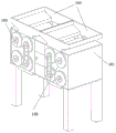
FIG. 1 is a schematic structural diagram of the invention;
FIG. 2 is a schematic structural view of the sectioning device of the present invention
FIG. 3 is a cross-sectional view of the sectioning device of the present invention;
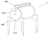
FIG. 4 is a schematic structural diagram of the drying apparatus according to the present invention;
FIG. 5 is an exploded view of the drying apparatus according to the present invention;
FIG. 6 is a schematic structural view of a first agitator according to the present invention;
FIG. 7 is a schematic structural view of a sealing flange according to the present invention;
FIG. 8 is a schematic structural view of a drying drum according to the present invention;
FIG. 9 is a sectional view of the drying drum of the present invention;
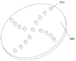
FIG. 10 is a schematic structural view of the vent disc of the present invention;
FIG. 11 is a schematic structural view of the crushing apparatus according to the present invention;
fig. 12 is an exploded view of the comminution apparatus according to the invention.
Detailed Description
The present invention will be further described with reference to the accompanying drawings.
The straw smashing device for preparing the biological fertilizer, which is shown in the attached drawings 1 to 12, comprises the straw smashing device for preparing the biological fertilizer, and is characterized in that: comprises a cutting device 1, a drying device 2 and a crushing device 3; the head and the tail of the first conveying device 4 are respectively arranged at the discharge opening of the cutting device 1 and the feed opening of the drying device 2, and the head and the tail of the second conveying device 5 are respectively arranged at the discharge opening of the drying device 2 and the feed opening of the crushing device 3. The straw that needs to smash is at first cut into the short little section through segmenting device 1, and first conveyer 4 conveys the straw to drying device 2 in afterwards, dries according to required temperature, and the straw is shifted to reducing mechanism 3 in through second conveyer 5 after the stoving, and the straw through drying device 2 becomes hard and fragile, and completion that can be easier is smashed, can solve like this because the straw moisture that just reaped is high, and the toughness is strong and difficult kibbling problem.
The section 1 cutting device comprises a shell 101, a cutter device 102 and at least two groups of compression roller devices 103; the upper part and the lower part of the shell 101 are respectively provided with a section feeding hole 104 and a section discharging hole 105, the compression roller device 103 and the cutter device 102 are arranged inside the shell 101, the compression roller device 103 is rotationally connected with the shell 101, and the cutter device 102 is arranged between two adjacent compression roller devices 103 and is in sliding connection with the shell 101;
the pressing roller device 103 includes four pressing rollers 106, and the four pressing rollers 106 rotate synchronously and are respectively arranged according to four vertexes of a rectangle.
The cutting device 102 comprises a cutter holder 107 and a blade 108, a feed bar 109 and a lead screw 110 are connected to the inside of the shell 101, the feed bar 109 and the lead screw 110 are arranged at the middle positions of the upper and lower compression rollers 106, the axes of the feed bar 109 and the lead screw 110 are parallel to the axes of the compression rollers 106, the cutter holder 107 is respectively connected with the feed bar 109 and the lead screw 110 in a sliding manner, two ends of the inside of the shell 101 are connected with limit switches, the limit switches are opposite to the cutter holder 107, the blade 108 is respectively connected to two sides of the cutter holder 107, and the blade 108 at least extends to the middle of the compression roller device. The cutter device 102 moves from one end of the press rollers 106 to the other end, and cuts the straw with both ends fixed between the press rollers 106. When the tool post 107 moves to one end of the press roller 106 and touches the limit switch, the motor drives the screw 110 to turn, and the tool post 107 drives the blade 108 to move reversely to the other end of the press roller 106, so that the reciprocating motion is performed to complete the cutting. The two compression rollers 106 with axes on the same horizontal plane complete synchronous motion through meshing of gears, the two compression rollers 106 with axes on the same horizontal plane are opposite in rotation direction, and one group of two compression rollers on the same vertical plane complete synchronous motion through driving of a synchronous belt. The motor driving the lead screw 110 and the motor driving the press roller 106 are different motors, respectively.
The drying cylinder 201 is provided with a first heat preservation cavity 209 and a second heat preservation cavity 210; the first heat preservation cavity 209 is coated on the outer side of the inner cavity of the drying cylinder 201, the second heat preservation cavity 210 is coated on the outer side of the first heat preservation cavity 209, and heat preservation liquid is filled in the second heat preservation cavity 210; the ventilating disc 207 is provided with a plurality of one-way valves 211, the sealing flange 208 is provided with a first communicating cavity 212, the first communicating cavity 212 is communicated with the inner cavity of the drying cylinder 201 through the one-way valves 211, the first communicating cavity 212 is also communicated with a first heat-preserving cavity 209, the first blocking plate 205 is provided with a plurality of silencing valves 213, and the first heat-preserving cavity 209 is communicated with the outside through the silencing valves 213; the hot-blast inner chamber that the air heater 219 blew out passes through check valve 211 via drying cylinder 201 gets into first communicating chamber 212, and rethread first heat preservation chamber 209 is blown out to the external world by muffler valve 213, and hot-blast at first carries out the drying to the straw, then will not fully refrigerated hot-blast blow to first heat preservation chamber 209 in, one then forms the one deck heat preservation to drying cylinder 201's inner chamber, and the second then heats the hot-blast heat of make full use of to the liquid in second heat preservation chamber 210.
The sealing flange 208 is further provided with a second communicating cavity 214, the second communicating cavity 214 is communicated with the second heat preservation cavity 210, and the sealing flange 208 is provided with a liquid exchange head which is communicated with the second communicating cavity 214.
The one-way valves 211 on the aeration disc 207 are distributed along a curve in a divergent way, and the divergent direction of the one-way valves 211 is opposite to the stirring direction of the first stirrer 204, so that straw can be prevented from blocking the one-way valves 211.
The first stirrer 204 comprises a central shaft 215 and a plurality of blades 216; the blades 216 are uniformly arranged along the outer surface of the central shaft 215, the two ends of each blade 216 are provided with a fold line-shaped rod 217, the outer ends of the fold line-shaped rods 217 are connected with the baffle 218, and the fold line-shaped blades 216 can improve the lifting height of the straws and improve the drying efficiency.
The crushing device 3 comprises a crushing barrel 301, a cover plate 302, a second stirrer 303 and a cutter head 304; cutterhead 304 swivelling joint is in the bottom of smashing bucket 301, apron 302 passes through support column 305 sliding connection in the upper portion of smashing bucket 301, support column 305 with smash bucket 301 swivelling joint, second agitator 303 sets up inside smashing bucket 301, and with apron 302 swivelling joint, the bottom of smashing bucket 301 is provided with crushing discharge gate 306. During loading, the cover plate 302 is removed.
The cutter head 304 comprises a cutter head body 307 and a plurality of cutter bodies 308, the cutter bodies 308 are arranged on the upper surface of the cutter head body 307 and distributed in a circular array, and the parts of the cutter bodies 308, which are close to the middle part of the cutter head body 307, are higher than the parts of the cutter bodies 308, which are close to the edge of the cutter head body 307. Because the dried straws are hard and brittle, the cutter head 304 can finish crushing after rotating at a high speed, and larger straws can be thrown to the edge of the crushing barrel 301 due to the action of centrifugal force, so that the cutter body 308 is easy to damage if the straws are too high.
The second stirrer 303 comprises a rotating shaft 309 and a plurality of stirring rod bodies 310, wherein the plurality of stirring rod bodies 310 are distributed on the outer surface of the rotating shaft 309 in a tower shape, and the lengths of the plurality of stirring rod bodies 310 are gradually reduced from bottom to top. The second agitator 303 functions to make the pulverization more uniform, and the agitation resistance placed at the bottom of the pulverizing barrel 301 is larger, so that the agitating bar body 310 is longer.
The above description is only of the preferred embodiments of the present invention, and it should be noted that: it will be apparent to those skilled in the art that various modifications and adaptations can be made without departing from the principles of the invention and these are intended to be within the scope of the invention.
Claims (6)
1. The utility model provides a straw reducing mechanism of preparation bio-fertilizer which characterized in that: comprises a cutting device (1), a drying device (2) and a crushing device (3); the head and the tail of the first conveying device (4) are respectively arranged at the discharge port of the cutting device (1) and the feed port of the drying device (2), and the head and the tail of the second conveying device (5) are respectively arranged at the discharge port of the drying device (2) and the feed port of the crushing device (3);
the cutting device (1) comprises a shell (101), a cutter device (102) and at least two groups of compression roller devices (103); the upper part and the lower part of the shell (101) are respectively provided with a section feeding hole (104) and a section discharging hole (105), the compression roller device (103) and the cutter device (102) are arranged inside the shell (101), the compression roller device (103) is rotationally connected with the shell (101), and the cutter device (102) is arranged between two adjacent compression roller devices (103) and is in sliding connection with the shell (101);
the pressing roller device (103) comprises four pressing rollers (106), the four pressing rollers (106) synchronously rotate and are respectively arranged according to four vertexes of a rectangle;
the drying device (2) comprises a drying cylinder (201), a drying feed inlet (202) and a drying discharge outlet (203) are respectively formed in the upper portion and the lower portion of the drying cylinder (201), a first stirrer (204) is rotatably connected in the drying cylinder (201), two ends of the drying cylinder (201) are respectively connected with a first blocking plate (205) and a second blocking plate (206), the second blocking plate (206) is a grid plate, the outer side of the second blocking plate (206) is connected with an air communicating disc (207), and the outer side of the air communicating disc (207) is connected with a sealing flange (208);
the drying cylinder (201) is provided with a first heat preservation cavity (209) and a second heat preservation cavity (210); the first heat preservation cavity (209) is coated on the outer side of the inner cavity of the drying cylinder (201), the second heat preservation cavity (210) is coated on the outer side of the first heat preservation cavity (209), and heat preservation liquid is arranged in the second heat preservation cavity (210); the ventilating disc (207) is provided with a plurality of one-way valves (211), the sealing flange (208) is provided with a first communicating cavity (212), the first communicating cavity (212) is communicated with the inner cavity of the drying cylinder (201) through the one-way valves (211), the first communicating cavity (212) is also communicated with a first heat-preserving cavity (209), the first blocking plate (205) is provided with a plurality of silencing valves (213), and the first heat-preserving cavity (209) is communicated with the outside through the silencing valves (213);
the sealing flange (208) is also provided with a second communicating cavity (214), the second communicating cavity (214) is communicated with the second heat preservation cavity (210), the sealing flange (208) is provided with a liquid exchange head, and the liquid exchange head is communicated with the second communicating cavity (214);
cutter device (102) includes blade holder (107) and blade (108), and casing (101) internal connection has feed rod (109) and lead screw (110), feed rod (109) and lead screw (110) set up in two upper and lower compression roller (106) intermediate position, the axis of feed rod (109) and lead screw (110) is parallel with the axis of compression roller (106), blade holder (107) respectively with feed rod (109) and lead screw (110) sliding connection, the inside both ends of casing (101) are connected with limit switch, limit switch is relative with blade holder (107), blade (108) connect respectively in the both sides of blade holder (107), blade (108) extend to compression roller device (103) middle part at least.
2. The straw crushing device for preparing the biological fertilizer as claimed in claim 1, wherein: the one-way valves (211) on the aeration disc (207) are distributed along a curve in a divergent mode, and the divergent direction of the one-way valves (211) is opposite to the stirring direction of the first stirrer (204).
3. The straw crushing device for preparing the biological fertilizer as claimed in claim 1, wherein: the first agitator (204) comprises a central shaft (215) and a plurality of blades (216); the blades (216) are uniformly arranged along the outer surface of the central shaft (215), the two ends of each blade (216) are provided with a fold-line-shaped rod (217), and the outer ends of the fold-line-shaped rods (217) are connected with the baffle (218).
4. The straw crushing device for preparing the biological fertilizer as claimed in claim 1, wherein: the crushing device (3) comprises a crushing barrel (301), a cover plate (302), a second stirrer (303) and a cutter head (304); blade disc (304) swivelling joint in the bottom of smashing bucket (301), apron (302) are through support column (305) sliding connection in the upper portion of smashing bucket (301), support column (305) and crushing bucket (301) swivelling joint, second agitator (303) set up inside smashing bucket (301), and with apron (302) swivelling joint, the bottom of smashing bucket (301) is provided with crushing discharge gate (306).
5. The straw crushing device for preparing the biological fertilizer as claimed in claim 4, wherein: the cutter head (304) comprises a cutter head body (307) and a plurality of cutter bodies (308), the cutter bodies (308) are arranged on the upper surface of the cutter head body (307) and distributed in a circular array mode, and the portions, close to the middle of the cutter head body (307), of the cutter bodies (308) are higher than the portions, close to the edge of the cutter head body (307), of the cutter bodies (308).
6. The straw crushing device for preparing the biological fertilizer as claimed in claim 4, wherein: the second stirrer (303) comprises a rotating shaft (309) and a plurality of stirring rod bodies (310), wherein the stirring rod bodies (310) are distributed on the outer surface of the rotating shaft (309) in a tower shape, and the lengths of the stirring rod bodies (310) are gradually reduced from bottom to top.
Priority Applications (1)
| Application Number | Priority Date | Filing Date | Title |
|---|---|---|---|
| CN201811196126.5A CN109511389B (en) | 2018-10-15 | 2018-10-15 | Straw reducing mechanism of preparation bio-fertilizer |
Applications Claiming Priority (1)
| Application Number | Priority Date | Filing Date | Title |
|---|---|---|---|
| CN201811196126.5A CN109511389B (en) | 2018-10-15 | 2018-10-15 | Straw reducing mechanism of preparation bio-fertilizer |
Publications (2)
| Publication Number | Publication Date |
|---|---|
| CN109511389A CN109511389A (en) | 2019-03-26 |
| CN109511389B true CN109511389B (en) | 2020-12-15 |
Family
ID=65772575
Family Applications (1)
| Application Number | Title | Priority Date | Filing Date |
|---|---|---|---|
| CN201811196126.5A Expired - Fee Related CN109511389B (en) | 2018-10-15 | 2018-10-15 | Straw reducing mechanism of preparation bio-fertilizer |
Country Status (1)
| Country | Link |
|---|---|
| CN (1) | CN109511389B (en) |
Families Citing this family (4)
| Publication number | Priority date | Publication date | Assignee | Title |
|---|---|---|---|---|
| CN111059865B (en) * | 2019-11-27 | 2023-07-14 | 秦子媛 | Continuous processing device for silage |
| CN111547540A (en) * | 2020-07-10 | 2020-08-18 | 潍坊驼王实业有限公司 | Polyester filament non-woven geotechnical cloth production is with preventing stifled loading attachment |
| CN112341256A (en) * | 2020-11-23 | 2021-02-09 | 黑龙江八一农垦大学 | Fertile fermenting installation of innoxious straw system |
| CN114080909B (en) * | 2021-11-10 | 2022-10-25 | 苏州市农业科学院 | Drying and crushing integrated machine |
Family Cites Families (8)
| Publication number | Priority date | Publication date | Assignee | Title |
|---|---|---|---|---|
| CN204093518U (en) * | 2014-10-08 | 2015-01-14 | 富阳思博工业设计有限公司 | A kind of novel foodstuff reducing mechanism |
| CN204665839U (en) * | 2015-06-04 | 2015-09-23 | 汤仁秀 | A kind of seed drier |
| CN205409601U (en) * | 2015-10-08 | 2016-08-03 | 上海中器环保科技有限公司 | Processing equipment of fruit vegetables discarded object production green -feed |
| CN105960961A (en) * | 2016-06-30 | 2016-09-28 | 哈尔滨尼亚农业有限公司 | Straw crushing device |
| CN207219464U (en) * | 2017-09-14 | 2018-04-13 | 南阳天冠生物质能发展有限公司 | A kind of biogas gas reducing mechanism |
| CN107537644A (en) * | 2017-09-26 | 2018-01-05 | 苏州美洁生环保工程有限公司 | A kind of kitchen garbage pulverizing lapping device |
| CN107843085B (en) * | 2017-11-02 | 2019-08-02 | 辽宁抚清助剂有限公司 | A kind of Horizontal stirring drying device of anti-material agglomeration |
| CN108200810A (en) * | 2018-02-24 | 2018-06-26 | 成都市国科泰达科技有限公司 | It is a kind of that there is the straw millstone of briquetting |
-
2018
- 2018-10-15 CN CN201811196126.5A patent/CN109511389B/en not_active Expired - Fee Related
Also Published As
| Publication number | Publication date |
|---|---|
| CN109511389A (en) | 2019-03-26 |
Similar Documents
| Publication | Publication Date | Title |
|---|---|---|
| CN109511389B (en) | Straw reducing mechanism of preparation bio-fertilizer | |
| CN108618183B (en) | Screening device is smashed in coarse fodder stoving | |
| CN213700157U (en) | Bio-organic fertilizer reducing mechanism | |
| CN205980640U (en) | Poultry fodder stoving agitating unit | |
| CN107694704B (en) | A kind of chemical industry prepares raw material grinding device with phloretin | |
| CN109604025A (en) | A kind of novel biomass processing equipment | |
| CN108745528A (en) | The broken drying integrated equipment discharged convenient for agriculture organic fertilizer | |
| JP4055895B2 (en) | Garbage disposal method and apparatus | |
| CN108855856B (en) | Agricultural soybean drying and impurity removing equipment | |
| CN212481941U (en) | Agricultural seed drying device | |
| CN108124617A (en) | A kind of stalk crushes installation for fermenting | |
| CN108741153A (en) | Multi-functional sweet potato processing unit | |
| CN209470464U (en) | The equipment uniformly baked for starch | |
| CN209073503U (en) | One kind having moisture-proof function poultry feed fermentor | |
| CN207694929U (en) | A kind of agricultural operation fertilizer production device with screening function | |
| CN206688828U (en) | A kind of broken crusher | |
| CN215638516U (en) | Photoinitiator absorption drying device | |
| CN113758179A (en) | Drying equipment for biomass fuel | |
| CN211575809U (en) | Quick drying device of licorice biological particle production usefulness | |
| CN108645154A (en) | A kind of production line and production method integrating Chinese medicine slice and drying | |
| CN205922839U (en) | Pig feed processing device | |
| CN205547149U (en) | Novel highland barley fine dried noodle machine | |
| CN108622541A (en) | A kind of agriculture feed storage device with dampproof effect | |
| CN209696842U (en) | A kind of solid fermentation Feed Manufacturing granulator | |
| CN219308921U (en) | Rubbing crusher with pretreatment function |
Legal Events
| Date | Code | Title | Description |
|---|---|---|---|
| PB01 | Publication | ||
| PB01 | Publication | ||
| SE01 | Entry into force of request for substantive examination | ||
| SE01 | Entry into force of request for substantive examination | ||
| TA01 | Transfer of patent application right |
Effective date of registration: 20201124 Address after: No.32-1-213, Jiankang Road, Gucheng street, Gaochun District, Nanjing City, Jiangsu Province Applicant after: Nanjing Chengte Automobile Service Co.,Ltd. Address before: Room 586, 291 Danfeng Road, Mudu Town, Wuzhong District, Suzhou City, Jiangsu Province Applicant before: SUZHOU JIHUI TECHNOLOGY Co.,Ltd. |
|
| TA01 | Transfer of patent application right | ||
| GR01 | Patent grant | ||
| GR01 | Patent grant | ||
| CF01 | Termination of patent right due to non-payment of annual fee |
Granted publication date: 20201215 Termination date: 20211015 |
|
| CF01 | Termination of patent right due to non-payment of annual fee |