Flowers and plants pruning equipment cultivated in a pot
Technical Field
The invention relates to the technical field of bonsai trimming, in particular to flower and grass potted plant trimming equipment.
Background
At present, potted plants are arranged in many places, which plays a great role in beautifying the environment, and the potted plants are not beautiful if growing freely, the potted plants are generally trimmed manually, which wastes time and labor, and the manual trimming can cause certain danger if the operation is careless, so that the invention of a flower and plant potted plant trimming device which can replace manual work and can trim the potted plants rapidly, beautifully and comprehensively is urgently needed.
Disclosure of Invention
In order to solve the problems, the invention provides a flower and grass pot trimming device, when the flower and grass pot trimming device is used, firstly, a machine is driven by a walking part to move to a pot position, then two bottom plates and two sliding bottom plates are drawn close to the middle to a proper position, then a base of a trimming part is jacked up above a flowerpot, sliding blocks of the base of the trimming part drive rotating rod parts, a sliding clamp of each rotating rod part drives a side trimming part to move up and down to trim the side surface of the pot, the top of the pot is rotationally trimmed by a top trimming part, the machine is stopped to push the two bottom plates and the two sliding bottom plates open after trimming is completed, the device is driven by the walking part to move to other places, the time of manual trimming is saved, the safety problem of manual trimming is avoided, the trimming efficiency is improved, and automatic trimming of the flower and grass pot.
The technical scheme adopted by the invention is as follows: a flower and plant pot culture trimming device comprises a base, a trimming part base, a rotating rod part, a side trimming part, a top trimming part and a walking part, wherein the trimming part base is positioned right above the base, and the bottom surfaces of two sliding bottom plates of the trimming part base are fixedly connected with piston rod ends of first hydraulic cylinders on the left side and the right side of the base; the rotating rod part is vertically arranged, and the lower end face of a second steering engine at the bottom of the rotating rod part is fixedly arranged on the upper end face of a sliding block of the base of the trimming part; the side trimming part is horizontally arranged, and the side of the sleeve part of the telescopic sleeve is fixedly connected with the side of the sliding clamp of the rotating rod; the top trimming part is positioned above the rotating rod part at the rear end of the left side of the trimming part base, and the bottom of the fixing frame of the top trimming part is fixedly connected with the side surface of the sliding card at the top of the rotating rod part at the rear end of the left side of the trimming part base; the walking part is positioned below the bottom plate of the base, and the top of a fixed shell of a fourth steering engine above the walking part is fixedly arranged in a groove below the bottom plate;
the base comprises a bottom plate, a first hydraulic cylinder, a first rotary hinged support, a first steering engine and a first hydraulic cylinder, the first hydraulic cylinder is vertically and upwards placed, and the bottom end of a cylinder body of the first hydraulic cylinder is fixedly arranged on the upper end surface of the bottom plate; the outer end of the first rotary hinged support is fixedly connected with the inner side of the baffle plate below the bottom plate; the first steering engine is vertically and upwards placed, the upper end face of the first steering engine is fixedly connected with the lower end face of the first rotating hinged support, and a steering engine shaft of the first steering engine is fixedly connected with a rotating shaft in the first rotating hinged support; the bottom end of the cylinder body and the end of the piston rod of the first hydraulic cylinder are fixedly connected with a rotating shaft in the first rotary hinged support; the first hydraulic cylinder is placed horizontally.
Furthermore, the pruning part base comprises a sliding bottom plate, a first rack, a sliding block, a second rotating hinged support and a second hydraulic cylinder, wherein the sliding bottom plate is a U-shaped plate, a U-shaped groove is formed in the upper surface of the sliding bottom plate, and the first rack is arranged in the U-shaped groove; the sliding block is slidably arranged in a U-shaped groove on the sliding bottom plate, a stepping motor fixedly connected with a gear is arranged in the sliding block, and the gear is meshed with the first rack; the bottom end of the second rotary hinged support is fixedly arranged on the inner side of a rear baffle of the sliding bottom plate; the second hydraulic cylinder is horizontally arranged, the bottom end of the cylinder body of the second hydraulic cylinder is rotatably connected with the rotating shaft of the second rotating hinged support on the left side, and the piston rod end of the second hydraulic cylinder is rotatably connected with the rotating shaft of the second rotating hinged support on the right side.
Furthermore, the flower and grass pot culture trimming device is characterized in that the rotating rod part comprises a rotating vertical rod, a second rack, a sliding clamp, a first stepping motor, a gear, a top plate and a second steering engine, the rotating vertical rod is a cuboid rod, the right side face of the rotating vertical rod is provided with the second rack, and the top of the rotating vertical rod is provided with the top plate; the sliding card is a hollow cuboid and is slidably arranged on the outer side of the rotating vertical rod; the first stepping motor is horizontally arranged, the side surface of the first stepping motor is fixedly arranged in a groove in the front of the sliding card, and a motor shaft of the first stepping motor is fixedly connected with the gear; the gear is meshed with the second rack; the second steering engine is vertically and upwards placed, and a steering engine shaft of the second steering engine is fixedly connected with the lower end of the rotating vertical rod.
Furthermore, the side trimming part comprises a telescopic sleeve, a third hydraulic cylinder, a second stepping motor base, a second stepping motor and a trimming wheel, wherein the telescopic sleeve is horizontally arranged, and the end of the telescopic sleeve is fixedly connected with the left surface of the second stepping motor base; the third hydraulic cylinder is horizontally arranged, the bottom end of a cylinder body of the third hydraulic cylinder is fixedly connected with a baffle plate of a sleeve part of the telescopic sleeve, and a piston rod end of the third hydraulic cylinder is fixedly connected with the baffle plate of the telescopic rod part of the telescopic sleeve; the second stepping motor is horizontally arranged, the bottom of the second stepping motor is fixedly arranged in a groove in the right of a base of the second stepping motor, and a motor shaft of the second stepping motor is fixedly connected with the trimming wheel.
Furthermore, the top trimming part comprises a fixing frame, a third steering engine, a fixed rod, a third stepping motor, a rotating chain and a cutting knife, wherein the fixing frame is of a structure consisting of three cuboids, the lower end of the fixing frame is provided with a round hole, and the upper end plate of the fixing frame is provided with a rotating shaft which is connected with the upper end face of the left third stepping motor; the third steering engine is vertically and upwards placed, the upper end face of the third steering engine is fixedly connected with the lower end face of the fixed frame, and a steering engine shaft of the third steering engine penetrates through a hole in the lower end of the fixed frame and is fixedly connected with the left end of a fixed rod below the third steering engine; the left end and the right end of the fixing rod are respectively fixedly connected with the inner sides of the fixing shells of the two third stepping motors; a third step that the motor is vertically arranged downwards, and a motor shaft of the motor is fixedly connected with rotating shafts at two ends inside the rotating chain; the outer side of the rotating chain is provided with a cutting knife.
Furthermore, the walking part of the pruning equipment for the flower and grass potted plants comprises a fourth steering engine, a wheel frame, a fourth stepping motor and wheels, wherein the fourth steering engine is vertically and downwards arranged, and a steering engine shaft of the fourth steering engine is fixedly connected with the upper end face of the wheel frame; the fourth stepping motor is horizontally arranged, the right side surface of the fourth stepping motor is fixedly connected with the left side of the wheel frame, and a motor shaft of the fourth stepping motor is fixedly connected with a rotating shaft in the wheel frame; the wheel is fixedly connected with a rotating shaft in the wheel frame.
The invention has the beneficial effects that: when the automatic trimming machine is used, the machine is driven to move to a potting position through the walking part, then the two bottom plates and the two sliding bottom plates are drawn to a proper position towards the middle, the base of the trimming part is jacked above the flowerpot, the sliding block of the base of the trimming part drives the rotating rod part, the sliding clamp of each rotating rod part drives the side trimming part to move up and down to trim the side surface of the potting, the top trimming part rotates to trim the top of the potting, the machine is stopped to push the two bottom plates and the two sliding bottom plates away after trimming is finished, and the walking part drives equipment to move to other places, so that the time for manual trimming is saved, the safety problem of manual trimming is avoided, the efficiency of trimming is improved, and automatic trimming of flower and grass potting is realized.
Drawings
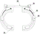
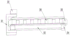
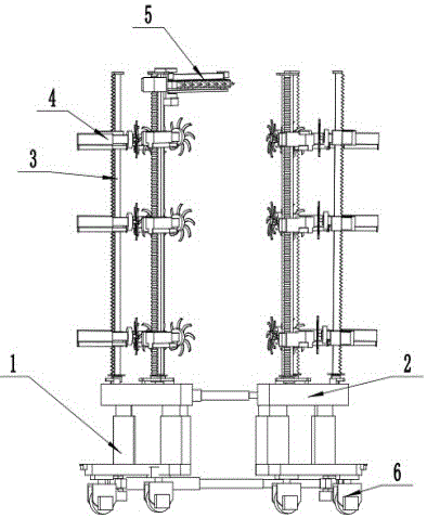
Fig. 1 and 2 are schematic overall structural diagrams of the present invention.
Fig. 3 is a schematic structural diagram of the base of the present invention.
Fig. 4 is a schematic structural view of the base of the trimming portion of the present invention.
Fig. 5 is a schematic structural view of the rotating lever of the present invention.
Fig. 6 is a schematic view of the structure of the side trimming part of the present invention.
Fig. 7 is a schematic view of the top trimming section of the present invention.
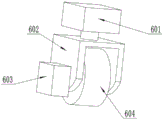
Fig. 8 is a schematic structural view of the walking part of the present invention.
Reference numerals: 1-a base; 2-trimming the partial base; 3-rotating the lever portion; 4-side trim part; 5-a top trim portion; 6-a walking part; 101-a base plate; 102-a first hydraulic cylinder; 103-a first rotary hinge base; 104-a first steering engine; 105-a first hydraulic cylinder; 201-a sliding bottom plate; 202-a first rack; 203-a slider; 204-a second swivel hinge mount; 205-a second hydraulic cylinder; 301-rotating the vertical rod; 302-a second rack; 303-slide card; 304-a first stepper motor; 305-a gear; 306-a top plate; 307-a second steering engine; 401-telescoping sleeve; 402-a third hydraulic cylinder; 403-second stepper motor base; 404-a second stepper motor; 405-a trimming wheel; 501-a fixing frame; 502-a third steering engine; 503-fixing rods; 504-a third stepper motor; 505-a rotating chain; 506-a cutter; 601-a fourth steering engine; 602-a wheel carrier; 603-a fourth stepper motor; 604-wheels.
Detailed Description
The technical scheme of the invention is further specifically described by the following embodiments and the accompanying drawings.
Embodiment as shown in fig. 1, fig. 2, fig. 3, fig. 4, fig. 5, fig. 6, fig. 7, fig. 8, a flower and grass potted plant trimming device comprises a base 1, a trimming portion base 2, a rotating rod portion 3, a side trimming portion 4, a top trimming portion 5 and a walking portion 6, wherein the trimming portion base 2 is positioned right above the base 1, and the bottom surfaces of two sliding bottom plates 201 are fixedly connected with the piston rod ends of first hydraulic cylinders 102 on the left and right sides of the base 1; the rotating rod part 3 is vertically arranged, and the lower end face of a second steering engine 307 at the bottom of the rotating rod part is fixedly arranged on the upper end face of a sliding block 203 of the trimming part base 2; the side trimming part 4 is horizontally arranged, and the side of the sleeve part of the telescopic sleeve 401 is fixedly connected with the side of the sliding card 303 of the rotating rod 3; the top trimming part 5 is positioned above the rotating rod part 3 at the rear end of the left side of the trimming part base 2, and the bottom of the fixing frame 501 is fixedly connected with the side surface of the sliding card 303 at the top of the rotating rod part 3 at the rear end of the left side of the trimming part base 2; the walking part 6 is positioned below the bottom plate 101 of the base 1, and the top of a fixed shell of a fourth steering engine 601 on the walking part is fixedly arranged in a groove below the bottom plate 101;
the base 1 comprises a bottom plate 101, a first hydraulic cylinder 102, a first rotary hinged support 103, a first steering engine 104 and a first hydraulic cylinder 105, wherein the first hydraulic cylinder 102 is vertically and upwards placed, and the bottom end of a cylinder body of the first hydraulic cylinder is fixedly arranged on the upper end surface of the bottom plate 101; the outer end of the first rotary hinged support 103 is fixedly connected with the inner side of the baffle plate below the bottom plate 101; the first steering engine 104 is vertically and upwards placed, the upper end face of the first steering engine is fixedly connected with the lower end face of the first rotating hinged support 103, and a steering engine shaft of the first steering engine is fixedly connected with a rotating shaft in the first rotating hinged support 103; the bottom end and the piston rod end of the first hydraulic cylinder 105 are fixedly connected with a rotating shaft in the first rotating hinged support 103; the first hydraulic cylinder 105 is horizontally disposed.
Further, the pruning part base 2 comprises a sliding bottom plate 201, a first rack 202, a sliding block 203, a second rotating hinge base 204 and a second hydraulic cylinder 205, wherein the sliding bottom plate 201 is a U-shaped plate, a U-shaped groove is formed in the upper surface of the sliding bottom plate, and the first rack 202 is arranged in the U-shaped groove; the sliding block 203 is slidably arranged in a U-shaped groove on the sliding bottom plate 201, a stepping motor fixedly connected with a gear is arranged in the sliding block, and the gear is meshed with the first rack 202; the bottom end of the second rotary hinged support 204 is fixedly arranged at the inner side of a rear baffle of the sliding bottom plate 201; the second hydraulic cylinder 205 is disposed horizontally, and the bottom end of the cylinder body is rotatably connected to the rotating shaft of the left second rotating hinge base 205, and the rod end of the piston is rotatably connected to the rotating shaft of the right second rotating hinge base 205.
Further, the rotating rod part 3 comprises a rotating vertical rod 301, a second rack 302, a sliding clamp 303, a first stepping motor 304, a gear 305, a top plate 306 and a second steering engine 307, wherein the rotating vertical rod 301 is a cuboid rod, the second rack 302 is arranged on the right side surface of the rotating vertical rod, and the top plate 306 is arranged at the top of the rotating vertical rod; the sliding card 303 is a hollow cuboid and is slidably mounted on the outer side of the rotating vertical rod 301; the first stepping motor 304 is horizontally arranged, the side surface of the first stepping motor is fixedly arranged in a groove in the front of the sliding card 303, and the motor shaft of the first stepping motor is fixedly connected with the gear 305; gear 305 intermeshes with the second rack 302; the second steering gear 307 is vertically placed upwards, and a steering gear shaft of the second steering gear is fixedly connected with the lower end of the vertical rotating rod 301.
Further, the side trimming part 4 of the trimming device for flowers and plants potted plants comprises a telescopic sleeve 401, a third hydraulic cylinder 402, a second stepping motor base 403, a second stepping motor 404 and a trimming wheel 405, wherein the telescopic sleeve 401 is horizontally arranged, and the end of the telescopic rod is fixedly connected with the left surface of the second stepping motor base 403; the third hydraulic cylinder 402 is horizontally arranged, the bottom end of the cylinder body of the third hydraulic cylinder is fixedly connected with a baffle plate of the sleeve part of the telescopic sleeve 401, and the piston rod end of the third hydraulic cylinder is fixedly connected with a baffle plate of the telescopic rod part of the telescopic sleeve 401; the second stepping motor 404 is horizontally disposed, and the bottom thereof is fixedly installed in a groove at the right of the second stepping motor base 403, and the motor shaft thereof is fixedly connected with the trimming wheel 405.
Further, the top trimming part 5 comprises a fixed frame 501, a third steering engine 502, a fixed rod 503, a third stepping motor 504, a rotating chain 505 and a cutting knife 506, wherein the fixed frame 501 is a structure formed by three cuboids, the lower end of the fixed frame is provided with a round hole, and the upper end plate of the fixed frame is provided with a rotating shaft which is connected with the upper end face of the left third stepping motor 504; a third steering engine 502 is vertically and upwards placed, the upper end face of the third steering engine is fixedly connected with the lower end face of the fixed frame 501, and a steering engine shaft of the third steering engine penetrates through a hole in the lower end of the fixed frame 501 and is fixedly connected with the left end of a fixed rod 503 below the third steering engine; the left and right ends of the upper fixing rod 503 are respectively fixedly connected with the inner sides of the fixing shells of the two third stepping motors 504; the third step motor 504 is vertically placed downwards, and the motor shaft of the third step motor is fixedly connected with the rotating shafts at the two ends inside the rotating chain 505; a cutter 506 is arranged outside the rotating chain 505.
Further, the walking part 6 of the pruning device for flowers and plants potted plants comprises a fourth steering engine 601, a wheel frame 602, a fourth stepping motor 603 and wheels 604, wherein the fourth steering engine 601 is vertically and downwardly arranged, and a steering engine shaft of the fourth steering engine is fixedly connected with the upper end face of the wheel frame 602; the fourth stepping motor 603 is horizontally arranged, the right side of the fourth stepping motor is fixedly connected with the left side of the wheel frame 602, and a motor shaft of the fourth stepping motor is fixedly connected with a rotating shaft in the wheel frame 602; the wheel 604 is fixedly connected with the rotating shaft in the wheel frame 602.
The working principle of the invention is as follows: when the potted plant trimming device is used, firstly, the direction is controlled by the fourth steering engine 601 of the walking part 6, the wheels 604 are driven by the fourth stepping motor 603 to drive the base 1 to drive the whole machine to move to a potted plant position, then the front openings of the two bottom plates 101 are controlled to be opened by the first steering engine 104 of the base 1 to wrap potted plants, the piston rods of the first hydraulic cylinder 105 and the second hydraulic cylinder 205 retract to drive the two bottom plates 101 and the two sliding bottom plates 201 to be close to proper positions towards the middle, the next step is to jack the trimming part base 2 above a flowerpot by extending the piston rod of the first hydraulic cylinder 102 of the base 1, the stepping motor in the sliding block 203 of the trimming part base 2 drives the sliding block 203 to drive the rotating rod parts 3 to slide in the U-shaped grooves on the sliding bottom plates 201, and then the first stepping motor 304 of each rotating rod part 3 drives the gear 305 to drive the sliding clamp 303 to drive the side face trimming clamp 303 of the The trimming part 4 moves up and down, the length of a telescopic sleeve 401 is controlled by the extension of a piston rod of a third hydraulic cylinder 402 of the side trimming part 4, a trimming wheel 405 is driven by a second stepping motor 404 to trim the side of the potted plant, a gear 305 is driven by a first stepping motor 304 of a rotating rod part 3 at the rear end of the left side of the base 2 to drive a sliding card 303 to drive a top trimming part 5 to a proper height, a rotating chain 505 is driven to rotate rapidly by a third stepping motor 504, a fixing rod 503 is driven by a third steering engine 502 to drive the rotating chain 505 to rotate the top of the potted plant, the machine is stopped after trimming is finished, then the two bottom plates 101 and the two sliding bottom plates 201 are pushed away by the extension of the piston rods of the first hydraulic cylinder 105 and the second hydraulic cylinder 205, and then the device is driven by a walking part.