Cross type flat heat pipe
Technical Field
The invention relates to the technical field of heat pipe heat dissipation, in particular to a crossed flat heat pipe.
Background
The heat pipe has the characteristics of quick thermal response, high heat conductivity coefficient and high heat flux density, is a high-efficiency heat transfer element, and is widely applied to heat and mass transfer equipment in the fields of aerospace, chemical engineering, metallurgy and the like. The flat heat pipe has the advantages of flat appearance and good contact with a heat exchange surface compared with the conventional heat pipe, and shows superiority in the heat dissipation environments of a plurality of plane heat sources, such as electronic chip heat dissipation, high-power LED lamp heat dissipation, power battery pack cooling and other application occasions.
The flat heat pipe may face a situation where the heat source area is large and has local hot spots in a specific application process. For example, a power battery pack of an electric vehicle is generally composed of dozens of hundreds of batteries arranged in an array, a large amount of heat is generated in the running process, and in order to ensure efficient and safe running of the electric vehicle, the temperature of the batteries is required to be lower than 40 ℃, and meanwhile, the temperature difference between the single batteries is controlled to be lower than 5 ℃. The battery thermal management system based on the flat heat pipe technology generally arranges a plurality of heat pipes at the bottom of a battery module in parallel, leads the heat of a battery out of a battery pack, and takes away the heat in a water cooling or air cooling mode, so that the heat dissipation of the battery pack is realized. However, due to the fact that the size of the battery pack is large, the path of the heat pipe in the heat transfer direction is long due to the arrangement mode that the single heat pipe penetrates through the battery pack, the total resistance loss of the working medium flowing in the pipe is increased due to the increase of the length of the pipe, and the overall heat exchange effect of the heat pipe is weakened. In addition, the cells near the center heat up faster than the cells at the edges, requiring greater cooling capacity. Therefore, the traditional heat pipe configuration and arrangement mode are difficult to meet the requirements of a larger plane heat source with local hot spots on heat dissipation and temperature uniformity.
Disclosure of Invention
The invention aims to provide a crossed flat heat pipe which can meet the requirements of large plane heat with local hot points and heat dissipation and temperature uniformity.
In order to achieve the above object, the present invention provides a cross-type flat heat pipe, wherein the cross-type flat heat pipe includes a plurality of strip-shaped flat heat pipe units disposed in the same plane, each of the flat heat pipe units has at least one end connected to an end or an edge of at least one other flat heat pipe unit of the plurality of flat heat pipe units, and an included angle is formed between every two connected flat heat pipe units.
The cross-type flat heat pipe unit comprises a plurality of flat heat pipe units, wherein a plurality of heat transfer channels are formed in each flat heat pipe unit, the heat transfer channels are located in the same plane and are parallel to each other, the extending direction of each heat transfer channel is the same as the length direction of the flat heat pipe unit, and the heat transfer channels are arranged at intervals along the width direction of the corresponding flat heat pipe unit.
The cross-type flat heat pipe as described above, wherein the first ends of the flat heat pipe units converge and connect in a direction approaching each other, the second ends of the flat heat pipe units extend and diverge in a direction away from each other, and the first end of each flat heat pipe unit is connected to the first ends of two adjacent flat heat pipe units.
The cross-type flat heat pipe as described above, wherein each of the heat transfer channels of each of the flat heat pipe units is an independent closed space.
The cross-type flat heat pipe as described above, wherein the heat transfer passages of one or more of the plurality of flat heat pipe units and the heat transfer passages of another one or more of the plurality of flat heat pipe units communicate with each other.
The cross-type flat heat pipe comprises a plurality of flat heat pipe units, wherein the first end of each flat heat pipe unit is connected with a working medium groove, and each heat transfer channel of each flat heat pipe unit is communicated with the working medium groove.
The cross-type flat heat pipe as described above, wherein the flat heat pipe unit includes a main flat heat pipe unit and a plurality of branch flat heat pipe units, the plurality of branch flat heat pipe units are distributed on two sides of the main flat heat pipe unit, and each branch flat heat pipe unit is vertically connected to the main flat heat pipe unit, and the heat transfer channel of the main flat heat pipe unit and the heat transfer channel of each branch flat heat pipe unit are independent closed spaces.
The cross-type flat heat pipe as described above, wherein the inside of each heat transfer channel is filled with a working medium.
The crossed flat heat pipe as described above, wherein the working medium is a liquid working medium.
Compared with the prior art, the invention has the following advantages:
the plurality of flat heat pipe units arranged on the crossed flat heat pipe can be in cross connection according to requirements, heat can be dissipated towards a plurality of directions when a heat source is dissipated, the heat transfer quantity of the heat source position is increased, and the temperature uniformity of a plane heat source with hot spots is effectively ensured while the heat exchange capacity is enhanced.
Drawings
The drawings are only for purposes of illustrating and explaining the present invention and are not to be construed as limiting the scope of the present invention. Wherein:
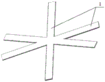
FIG. 1 is a schematic structural diagram of a cross-type planar heat pipe provided by the present invention;
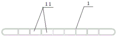
FIG. 2 is a schematic diagram of the internal structure of a planar heat pipe unit of the cross-type planar heat pipe provided by the present invention;
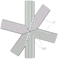
FIG. 3 is a schematic diagram of the internal structure of the cross-shaped planar heat pipe provided by the present invention;
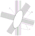
FIG. 4 is a schematic diagram of another internal structure of the cross-shaped planar heat pipe provided by the present invention;
FIG. 5 is a schematic view of another internal structure of the cross-shaped planar heat pipe provided by the present invention;
FIG. 6 is a schematic view of another cross-shaped planar heat pipe structure provided by the present invention;
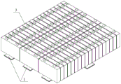
fig. 7 is a schematic diagram of a usage state of the cross-type planar heat pipe provided in fig. 6 when the cross-type planar heat pipe is applied to heat dissipation of a battery pack.
The reference numbers illustrate:
1. a flat heat pipe unit;
11. a heat transfer channel;
12. a main flat heat pipe unit;
13. a branched flat heat pipe unit;
2. a working medium groove;
3. heat source
Detailed Description
In order to clearly understand the technical solution, the purpose and the effect of the present invention, a detailed description of the present invention will be described with reference to the accompanying drawings.
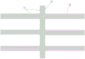
As shown in fig. 1 to 6, the present invention provides a cross-type flat heat pipe, wherein the cross-type flat heat pipe includes a plurality of strip-shaped flat heat pipe units 1 disposed in the same plane, each flat heat pipe unit 1 has at least one end connected to an end or an edge of at least one other flat heat pipe unit 1 of the plurality of flat heat pipe units 1, and an included angle is formed between every two connected flat heat pipe units 1, that is, the plurality of flat heat pipe units 1 are cross-connected, so that heat dissipation in different directions can be effectively satisfied; in addition, compared with a long-strip-shaped flat heat pipe extending from one side of a heat source to the other side of the heat source in the prior art, the flat heat pipe unit 1 used by the invention has the advantages that the length is greatly shortened, so that the path length of the flat heat pipe unit 1 in the heat transfer direction is effectively shortened, the total flow resistance loss of a working medium is reduced, the heat exchange capacity of the flat heat pipe unit 1 on a longer path is improved in a limited space, meanwhile, the effect of locally strengthening heat dissipation is realized, and the heat exchange effect of the flat heat pipe unit 1 is ensured; the heat transfer quantity of the original position of the heat can be increased by increasing the number of the flat heat pipe units 1, namely improving the distribution density of the flat heat pipe units 1, and the requirements of a larger plane heat source with local hot spots on heat dissipation and temperature uniformity are met; it should be noted that the number and connection mode of the flat heat pipe units 1 in the present invention can be specifically designed according to the heat source to be applied, and the present invention is not limited thereto.
Further, as shown in fig. 2 to fig. 6, in the cross-type flat heat pipe provided by the present invention, a plurality of heat transfer channels 11 located in the same plane and parallel to each other are formed inside each flat heat pipe unit 1, the extending direction of each heat transfer channel 11 is the same as the length direction of the flat heat pipe unit 1, and each heat transfer channel 11 is arranged at intervals along the width direction of the corresponding flat heat pipe unit 1, each heat transfer channel 11 is filled with a working medium, according to different working conditions, the liquid working medium can be selected from solutions such as acetone or secondary distilled water, the working medium is heated, evaporated, cooled and condensed in the heat transfer channel 11, and meanwhile, the slender heat transfer channel 11 provides a capillary force required by the working medium transmission, so as to implement gas flow, thereby implementing heat transmission and circulation in the heat transfer channel 11 of the flat heat pipe unit 1.
Further, as shown in fig. 1 and fig. 3 to 5, in the cross-type flat heat pipe provided by the present invention, the first ends of the flat heat pipe units 1 are gathered and connected in a direction approaching each other, the second ends of the flat heat pipe units 1 extend and diverge in a direction away from each other, and the first end of each flat heat pipe unit 1 is connected to the first ends of two adjacent flat heat pipe units 1, which can be understood that the plurality of flat heat pipe units 1 are connected in a star-shaped cross manner.
As a preferred embodiment of the present invention, as shown in fig. 1 and fig. 3 to fig. 5, the number of the flat heat pipe units 1 may be six, and it should be noted that, the setting of six flat heat pipe units 1 is only a preferred embodiment of the present invention, and the present invention is not limited thereto.
Furthermore, as shown in fig. 3, in the cross-type flat heat pipe provided by the present invention, each heat transfer channel 11 of each flat heat pipe unit 1 is an independent closed space, the working medium in each heat transfer channel 11 is respectively subjected to heat transmission and circulation in the corresponding heat transfer channel 11, and each heat transfer channel 11 is set as an independent closed space, so that the transmission length of the working medium in each heat transfer channel 11 can be effectively limited, and the situation that the transmission length of the working medium is too long to reduce the heat transfer effect is avoided.
Further, as shown in fig. 4, in the cross-type flat heat pipe provided by the present invention, the heat transfer channels 11 of one or more flat heat pipe units 1 in the plurality of flat heat pipe units 1 are communicated with the heat transfer channels 11 of another one or more flat heat pipe units 1 in the plurality of flat heat pipe units 1, that is, the heat transfer channels 11 of each flat heat pipe unit 1 can be selectively communicated with the heat transfer channels 11 of other flat heat pipe units 1, for example, since the heat at the edge of the heat source is easily dissipated, in order to ensure the temperature uniformity of the heat source, the two or more flat heat pipe units 1 corresponding to the edge of the heat source can be set to be communicated with each other, so as to reduce the heat dissipation efficiency of the flat heat pipe unit 1 corresponding to the edge of the heat source, and avoid the occurrence of the situation that the temperature difference between the center of the heat source and the edge is large.
Furthermore, as shown in fig. 5, the present invention provides a cross-type flat heat pipe, wherein the first end of each flat heat pipe unit 1 is connected to a working medium tank 2, and each heat transfer channel 11 of each flat heat pipe unit 1 is communicated with the working medium tank 2. When the heat dissipation device is arranged, the position of the working medium groove 2 can be opposite to the hot spot position of the heat source, so that the working medium can transmit heat from the working medium groove 2 to the heat transmission channels 11 of the flat heat pipe units 1, and the heat dissipation can be carried out on the hot spot position more quickly.
Preferably, as shown in fig. 1 and fig. 3 to 5, when a plurality of flat heat pipe units 1 are provided, the angle between every two adjacent flat heat pipe units 1 may be different according to the shape of the heat source, so as to ensure the temperature uniformity requirement of the heat source.
Further, as shown in fig. 6 and 7, the cross-type flat heat pipe provided by the present invention further provides an embodiment, wherein the flat heat pipe unit 1 includes a main flat heat pipe unit 12 and a plurality of branch flat heat pipe units 13, the plurality of branch flat heat pipe units 13 are distributed on two sides of the main flat heat pipe unit 12, each branch flat heat pipe unit 13 is vertically connected to the main flat heat pipe unit 12, and the heat transfer channels 11 of the main flat heat pipe unit 12 and the heat transfer channels 11 of each branch flat heat pipe unit 13 are independent closed spaces. Connecting a plurality of flat heat pipe units 1 in a vertical manner has the advantage of being convenient for processing, and for a rectangular heat source 3 like that shown in fig. 7, the connection between the flat heat pipe units 1 can be realized in a vertical connection manner.
Compared with the prior art, the invention has the following advantages:
the plurality of flat heat pipe units arranged on the crossed flat heat pipe can be in cross connection according to requirements, heat can be dissipated towards a plurality of directions when a heat source is dissipated, the heat transfer quantity of the heat source position is increased, and the temperature uniformity of a plane heat source with hot spots is effectively ensured while the heat exchange capacity is enhanced.
The above description is only an exemplary embodiment of the present invention, and is not intended to limit the scope of the present invention. Any equivalent changes and modifications that can be made by one skilled in the art without departing from the spirit and principles of the invention should fall within the protection scope of the invention.