CN109311043B - Liquid material discharge device, and coating device and coating method therefor - Google Patents
Liquid material discharge device, and coating device and coating method therefor Download PDFInfo
- Publication number
- CN109311043B CN109311043B CN201780034025.5A CN201780034025A CN109311043B CN 109311043 B CN109311043 B CN 109311043B CN 201780034025 A CN201780034025 A CN 201780034025A CN 109311043 B CN109311043 B CN 109311043B
- Authority
- CN
- China
- Prior art keywords
- liquid material
- valve
- valve rod
- actuator
- valve stem
- Prior art date
- Legal status (The legal status is an assumption and is not a legal conclusion. Google has not performed a legal analysis and makes no representation as to the accuracy of the status listed.)
- Active
Links
Images


Classifications
-
- B—PERFORMING OPERATIONS; TRANSPORTING
- B05—SPRAYING OR ATOMISING IN GENERAL; APPLYING FLUENT MATERIALS TO SURFACES, IN GENERAL
- B05C—APPARATUS FOR APPLYING FLUENT MATERIALS TO SURFACES, IN GENERAL
- B05C5/00—Apparatus in which liquid or other fluent material is projected, poured or allowed to flow on to the surface of the work
- B05C5/02—Apparatus in which liquid or other fluent material is projected, poured or allowed to flow on to the surface of the work the liquid or other fluent material being discharged through an outlet orifice by pressure, e.g. from an outlet device in contact or almost in contact, with the work
- B05C5/0225—Apparatus in which liquid or other fluent material is projected, poured or allowed to flow on to the surface of the work the liquid or other fluent material being discharged through an outlet orifice by pressure, e.g. from an outlet device in contact or almost in contact, with the work characterised by flow controlling means, e.g. valves, located proximate the outlet
-
- B—PERFORMING OPERATIONS; TRANSPORTING
- B05—SPRAYING OR ATOMISING IN GENERAL; APPLYING FLUENT MATERIALS TO SURFACES, IN GENERAL
- B05C—APPARATUS FOR APPLYING FLUENT MATERIALS TO SURFACES, IN GENERAL
- B05C11/00—Component parts, details or accessories not specifically provided for in groups B05C1/00 - B05C9/00
- B05C11/10—Storage, supply or control of liquid or other fluent material; Recovery of excess liquid or other fluent material
- B05C11/1002—Means for controlling supply, i.e. flow or pressure, of liquid or other fluent material to the applying apparatus, e.g. valves
- B05C11/1026—Valves
-
- B—PERFORMING OPERATIONS; TRANSPORTING
- B05—SPRAYING OR ATOMISING IN GENERAL; APPLYING FLUENT MATERIALS TO SURFACES, IN GENERAL
- B05C—APPARATUS FOR APPLYING FLUENT MATERIALS TO SURFACES, IN GENERAL
- B05C11/00—Component parts, details or accessories not specifically provided for in groups B05C1/00 - B05C9/00
- B05C11/10—Storage, supply or control of liquid or other fluent material; Recovery of excess liquid or other fluent material
- B05C11/1002—Means for controlling supply, i.e. flow or pressure, of liquid or other fluent material to the applying apparatus, e.g. valves
- B05C11/1034—Means for controlling supply, i.e. flow or pressure, of liquid or other fluent material to the applying apparatus, e.g. valves specially designed for conducting intermittent application of small quantities, e.g. drops, of coating material
-
- B—PERFORMING OPERATIONS; TRANSPORTING
- B05—SPRAYING OR ATOMISING IN GENERAL; APPLYING FLUENT MATERIALS TO SURFACES, IN GENERAL
- B05C—APPARATUS FOR APPLYING FLUENT MATERIALS TO SURFACES, IN GENERAL
- B05C11/00—Component parts, details or accessories not specifically provided for in groups B05C1/00 - B05C9/00
- B05C11/10—Storage, supply or control of liquid or other fluent material; Recovery of excess liquid or other fluent material
- B05C11/1047—Apparatus or installations for supplying liquid or other fluent material comprising a buffer container or an accumulator between the supply source and the applicator
-
- B—PERFORMING OPERATIONS; TRANSPORTING
- B05—SPRAYING OR ATOMISING IN GENERAL; APPLYING FLUENT MATERIALS TO SURFACES, IN GENERAL
- B05C—APPARATUS FOR APPLYING FLUENT MATERIALS TO SURFACES, IN GENERAL
- B05C5/00—Apparatus in which liquid or other fluent material is projected, poured or allowed to flow on to the surface of the work
- B05C5/02—Apparatus in which liquid or other fluent material is projected, poured or allowed to flow on to the surface of the work the liquid or other fluent material being discharged through an outlet orifice by pressure, e.g. from an outlet device in contact or almost in contact, with the work
- B05C5/0225—Apparatus in which liquid or other fluent material is projected, poured or allowed to flow on to the surface of the work the liquid or other fluent material being discharged through an outlet orifice by pressure, e.g. from an outlet device in contact or almost in contact, with the work characterised by flow controlling means, e.g. valves, located proximate the outlet
- B05C5/0237—Fluid actuated valves
-
- B—PERFORMING OPERATIONS; TRANSPORTING
- B05—SPRAYING OR ATOMISING IN GENERAL; APPLYING FLUENT MATERIALS TO SURFACES, IN GENERAL
- B05C—APPARATUS FOR APPLYING FLUENT MATERIALS TO SURFACES, IN GENERAL
- B05C5/00—Apparatus in which liquid or other fluent material is projected, poured or allowed to flow on to the surface of the work
-
- B—PERFORMING OPERATIONS; TRANSPORTING
- B05—SPRAYING OR ATOMISING IN GENERAL; APPLYING FLUENT MATERIALS TO SURFACES, IN GENERAL
- B05D—PROCESSES FOR APPLYING FLUENT MATERIALS TO SURFACES, IN GENERAL
- B05D1/00—Processes for applying liquids or other fluent materials
- B05D1/26—Processes for applying liquids or other fluent materials performed by applying the liquid or other fluent material from an outlet device in contact with, or almost in contact with, the surface
-
- F—MECHANICAL ENGINEERING; LIGHTING; HEATING; WEAPONS; BLASTING
- F16—ENGINEERING ELEMENTS AND UNITS; GENERAL MEASURES FOR PRODUCING AND MAINTAINING EFFECTIVE FUNCTIONING OF MACHINES OR INSTALLATIONS; THERMAL INSULATION IN GENERAL
- F16K—VALVES; TAPS; COCKS; ACTUATING-FLOATS; DEVICES FOR VENTING OR AERATING
- F16K1/00—Lift valves or globe valves, i.e. cut-off apparatus with closure members having at least a component of their opening and closing motion perpendicular to the closing faces
- F16K1/32—Details
- F16K1/34—Cutting-off parts, e.g. valve members, seats
- F16K1/42—Valve seats
Abstract
The invention provides a liquid material discharge device and method, which can restrain the generation of air bubbles caused by the lifting action of a rod under the negative pressure environment. Provided are a liquid material discharge device and a method thereof, which solve the problem of liquid material leakage caused by insufficient closing of a valve rod tip due to abrasion of the valve rod tip or a valve seat. A liquid material discharge device is provided with: a storage vessel; a compressed gas supply source that pressurizes the storage container; a nozzle provided with a discharge flow path; a valve rod which performs reciprocating motion; an actuator that drives the valve rod; a valve seat having a communication hole communicating with the discharge flow path; and a discharge control device for controlling the actuator and opening/closing the communication hole by the front end of the valve rod; and is used in the negative pressure space, the discharge control device controls the acceleration time (Au) of the valve rod rising by the actuator within the range of 2-300 [ ms ], thereby preventing the generation of air bubbles along with the rising of the valve rod.
Description
Technical Field
The present invention relates to a device and a method for discharging a liquid material under a negative pressure environment. The "negative pressure environment" in the present specification includes a vacuum environment.
Background
In a process of applying a liquid resin (liquid material) to a substrate on which a semiconductor component or the like is mounted (for example, packaging or underfill), if bubbles are present in the liquid material, various adverse effects are caused, such as uneven discharge amount, irregular application shape or application position (scattering of drawn lines), excessive liquid which is discharged simultaneously with discharge and splashes the liquid material being adhered to the periphery of the discharge port of the nozzle, and the like.
As a method for eliminating the adverse effect of the bubbles, there is a method of degassing a liquid material by placing the liquid material in a vacuum environment. The most common method for degassing is a method in which a container (syringe) storing a liquid material for actual work is directly placed in another closed container before the work is performed, and the liquid material is degassed by vacuum-sucking the inside of the closed container. As another method, a coating apparatus has been proposed in which a space to be coated is a closed space, and the inside of the space is vacuum-sucked to degas the liquid material.
For example, patent document 1 is a coating apparatus as follows: a liquid material application device which is provided with a storage and discharge unit for storing a liquid material and discharging the liquid material from a discharge port and applies the liquid material to an object to be applied, the liquid material application device comprising: an application space surrounding at least the accommodating discharge section and the object to be applied; and an exhaust system for discharging the liquid material from the storage and discharge unit to the object to be coated by setting the coating space to a negative pressure state and setting the coating space to a negative pressure state.
Further, patent document 2 is a coating apparatus as follows: the vacuum coating device is characterized in that a coated article for supplying liquid resin is arranged in a vacuum chamber, the liquid resin is supplied from a distributor for supplying the liquid resin to a specified position of the coated article under vacuum, a1 st container part for accommodating and supporting the coated article and a2 nd container part for installing a nozzle of the distributor form a vacuum chamber for accommodating the coated article, the 1 st container part and the 2 nd container part are set to be relatively movable in an X-Y plane without destroying the airtight state of the vacuum chamber, an X-Y driving part is arranged outside the vacuum chamber, at least one of the 1 st container part and the 2 nd container part moves in the X-Y plane, and the relative plane position of the coated article and the nozzle is variable.
Documents of the prior art
Patent document
Patent document 1: japanese patent laid-open publication No. 2005-211874
Patent document 2: japanese patent laid-open publication No. 2007-111862
Disclosure of Invention
Technical problem to be solved by the invention
In the case where the discharge device is disposed in the negative pressure space to perform the coating operation, in the discharge device including the valve stem (plunger) which reciprocates, the liquid pressure in the vicinity of the stem tip is lowered by the raising operation of the valve stem, and a problem arises that air bubbles are generated. If bubbles are generated near the tip of the valve stem, problems such as scattering of the drawing line due to the bubbles and splashing of the liquid material during discharge occur.
Accordingly, an object of the present invention is to provide a liquid material discharge device and method that can suppress the generation of bubbles due to the raising operation of a lever in a negative pressure environment.
Further, an object of the present invention is to provide a liquid material discharge device and method that solve the problem of leakage of a liquid material caused by insufficient closing of a stem tip due to abrasion of the stem tip or a valve seat.
Means for solving the problems
A liquid material discharge device according to a first aspect of the present invention includes: a storage container that stores a liquid material; a compressed gas supply source that pressurizes the storage container; a nozzle provided with a discharge flow path; a valve rod which performs reciprocating motion; an actuator that drives the valve rod; a valve seat having a communication hole communicating with the discharge flow path; and a discharge control device for controlling the actuator and opening/closing the communication hole by the front end of the valve rod; the liquid material discharge device is used in a negative pressure space; the discharge control device controls the valve rod to ascend by using the actuator for an acceleration time AuControlled at 2-300 [ ms ]]Thereby preventing generation of bubbles accompanying the rise of the valve stem.
In the liquid material discharge device, the liquid material discharge device may further include: the discharge control device sets a target speed V at the time of raising the valve stem by the actuator1Controlled at 0.2-30 [ mm/s ]]Within the range of (1).
In the liquid material discharge device, the liquid material discharge device may further include: the above-mentioned dischargeThe control device uses the acceleration time A when the valve rod of the actuator descendsdControlled at 2-300 [ ms ]]In this case, the following characteristics may be applied: the discharge control device uses the acceleration time A of the valve rod when the actuator ascendsuAnd acceleration time A at the time of descentdThe settings are the same.
In the liquid material discharge device, the liquid material discharge device may further include: in the case where the actuator uses, as a drive source, a motor capable of controlling the forward position of the valve stem by the discharge control device, the actuator may be characterized in that: the actuator may be configured such that a motor selected from a stepping motor, a servo motor, and a linear motor is used as a drive source, and further, the actuator may be configured such that: the disclosed device is provided with: and a position detection mechanism for detecting that the tip of the valve rod is positioned to close the valve seat.
A liquid material discharge device according to a second aspect of the present invention includes: a storage container that stores a liquid material; a compressed gas supply source that pressurizes the storage container; a nozzle provided with a discharge flow path; a valve rod which performs reciprocating motion; an actuator that drives the valve rod; a valve seat having a communication hole communicating with the discharge flow path; and a discharge control device for controlling the actuator and opening/closing the communication hole by the front end of the valve rod; the disclosed device is provided with: and a position detection mechanism for detecting that the tip of the valve rod is positioned to close the valve seat.
In the liquid material discharge device according to the second aspect, the liquid material discharge device may further include: in the case where the actuator uses, as a drive source, a motor capable of controlling the forward position of the valve stem by the discharge control device, the actuator may be characterized in that: the actuator uses a motor selected from a stepping motor, a servo motor, and a linear motor as a driving source.
In the liquid material discharge device including the position detection mechanism, the liquid material discharge device may include: the position detection mechanism includes: a sliding member connected to the actuator; a slider connected with the sliding member; a sensor mechanism that detects that the slide member is located at a predetermined position; a stem link member connected to the valve stem and disposed in separable contact with the slide member; and an elastic member that gives an urging force that detachably urges the lever link member and the slide member into contact with each other; when the actuator further advances the valve rod after the valve rod is in contact with the valve seat, the slide member is separated from the rod interlocking member and moves downward, and the movement of the slide member is detected by the sensor mechanism, thereby detecting that the tip end of the valve rod is positioned to close the valve seat.
In the liquid material discharge device including the rod interlocking member, the liquid material discharge device may include: in the case where the rod interlocking member is connected to the slider, and the elastic member is a tension coil spring connecting the rod interlocking member and the slide member, the elastic member may be characterized in that: the elastic member has an initial tension Pi equal to a force that can move the lever interlocking member and the slide member when the valve lever is not in contact with the valve seat.
In the liquid material discharge device including the rod interlocking member, the liquid material discharge device may include: the sliding member includes: a top surface having a1 st through hole through which the valve stem is inserted; and a bottom surface having a2 nd through hole through which the valve rod is inserted; the lever interlocking member and the elastic member are disposed between the top surface and the bottom surface of the slide member, and the elastic member detachably abuts the lever interlocking member against the top surface or the bottom surface of the slide member, in which case: further provided with: a fixing member through which the valve rod is inserted and which fixes the rod link member, wherein the elastic member is a compression coil spring through which the valve rod is inserted, and further, the valve device may be characterized in that: the elastic member has a repulsive force Pii equivalent to a force required to move the valve stem, the stem link member, and the fixed member.
In the liquid material discharge device, the liquid material discharge device may further include: the disclosed device is provided with: a1 st guide member through which the valve rod is inserted and which guides a linear movement of the valve rod; and a2 nd guide member through which the valve rod is inserted and which guides the linear movement of the valve rod below the 1 st guide member, wherein: the disclosed device is provided with: and a 3 rd guide member through which the valve rod is inserted, and guiding a linear movement of the valve rod below the 2 nd guide member.
The coating device of the present invention is characterized by comprising: the liquid material discharge device; a workpiece table on which a workpiece is set; a relative driving device for relatively moving the liquid material ejecting device and the workpiece table; a cover constituting a negative pressure space in which the liquid material discharge device, the work stage, and the counter drive device are disposed; a pressure reducing device for setting the inside of the cover to a negative pressure; and a drive control device for controlling the relative drive device.
In the above coating apparatus, the coating apparatus may further include: the pressure reducing means is a vacuum pump.
The coating method of the present invention is a coating method using the coating apparatus, and is characterized in that the liquid material is coated on the work while relatively moving the work and the liquid material discharge apparatus in a state where the inside of the cap is set to a negative pressure by the decompression apparatus.
In the above coating method, the coating method may further include: the interior of the housing is substantially evacuated.
ADVANTAGEOUS EFFECTS OF INVENTION
According to the present invention, by suppressing the generation of air bubbles due to the raising operation of the valve stem, it is possible to prevent problems such as scattering of the drawn line and splashing of the liquid material at the time of discharge.
Further, since the liquid material is fed under pressure by the compressed gas and the valve rod is opened and closed, the discharge can be performed stably at high speed (high flow rate) with good responsiveness.
Further, in the present invention including the position detection mechanism, even if the valve rod tip or the valve seat is worn, the valve rod tip can be reliably closed.
Drawings
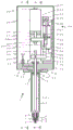
Fig. 1 is a partial cross-sectional side view of a discharge device according to a first embodiment.
Fig. 2 is an a-a arrow view of fig. 1.
Fig. 3 is a view of the arrow B-B in fig. 1.
Fig. 4 is an explanatory diagram illustrating an operation when the valve stem of the discharge device according to the first embodiment is raised.
Fig. 5 is an explanatory diagram for explaining an operation when the valve stem of the discharge device according to the first embodiment is lowered.
Fig. 6 is an explanatory diagram for explaining an operation at the time of detecting the contact of the valve stem in the discharge device according to the first embodiment.
Fig. 7 is a schematic perspective view of the coating apparatus according to the first embodiment.
Fig. 8 is a partial cross-sectional side view of the discharge device according to the second embodiment.
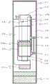
Fig. 9 is a partially sectional front view of a discharge device according to a third embodiment.
Fig. 10 is a view of the arrows C-C in fig. 9.
Fig. 11 is an explanatory diagram for explaining an operation when the valve stem of the discharge device according to the third embodiment is raised.
Fig. 12 is an explanatory diagram for explaining an operation when the valve stem of the discharge device according to the third embodiment is lowered.
Fig. 13 is an explanatory diagram for explaining an operation at the time of detecting the contact of the valve stem in the discharge device according to the third embodiment.
Fig. 14 is a partial cross-sectional front view of a discharge device according to a fourth embodiment.
Fig. 15 is a partial cross-sectional view of a discharge device according to a fifth embodiment. Wherein, (a) is a front view, and (b) is a D-D arrow view in (a).
Fig. 16 is a partial cross-sectional view of a discharge device according to a sixth embodiment. Wherein, (a) is a front view, and (b) is an E-E arrow view in (a).
Fig. 17 is a graph (schematic diagram) illustrating acceleration/deceleration time when the valve stem is raised.
Detailed Description
Hereinafter, embodiments for carrying out the present invention will be described.
First embodiment
The discharge device 1 according to the first embodiment of the present invention is a type of discharge device that discharges a liquid material by opening the communication hole 7 of the valve seat 6 by the ascending operation of the valve stem 21 and stops the discharge by closing by the descending operation of the valve stem 21, and is mounted on the application device 101 in a negative pressure space and used. In the discharge device 1, the discharge control device 33 controls the operation of the electric actuator 28 to adjust the speed or acceleration of the valve stem 21, thereby preventing the generation of air bubbles. Further, the position detection mechanism 34 that detects the position at which the valve stem 21 and the valve seat 6 come into contact with each other is provided, and even when the valve stem 21 or the valve seat 6 is worn, the communication hole 7 of the valve seat 6 can be reliably closed.
Hereinafter, the structure of the discharge device 1 will be described first, and the operation thereof will be described next.
< Structure >
Fig. 1 is a partial cross-sectional view of a discharge device 1 according to an embodiment of the present invention. In addition, fig. 2 is an a-a arrow view in fig. 1, and fig. 3 is a B-B arrow view in fig. 1. In the following description, the actuator 28 side is sometimes referred to as "up" and the nozzle 3 side is sometimes referred to as "down". The viewpoint of fig. 1 may be referred to as "front view", and the viewpoints of fig. 2 and 3 may be referred to as "side view".
The discharge device 1 includes a storage container (syringe) 2, a nozzle 3, a nozzle mounting member 5, a valve seat 6, a body lower member 10, and a position detection mechanism 34.
The storage container 2 used in the first embodiment is a general resin syringe having a flange portion 9 at an upper end portion and an inner cylinder 8 at a lower end portion. A valve stem 21 is inserted into the storage container 2, and an inner space of the inner cylinder 8 forms a stem tip insertion hole. The nozzle mounting member 5, the valve seat 6, and the nozzle 3 are mounted on the inner cylinder 8.
The nozzle 3 is a tubular member, and the inner space constitutes the discharge flow path 4. The nozzle attachment member 5 is screwed to the lower end of the syringe 2, whereby the discharge flow path 4 of the syringe 2 and the nozzle 3 communicates with each other through the valve seat 6.
The nozzle mounting member 5 is a cylindrical member, and has a through hole in the bottom surface thereof, into which the nozzle 3 is inserted.
The valve seat 6 is attached to a recess of the nozzle attachment member 5, and is fixed so as to be sandwiched between the nozzle attachment member 5 and an inner cylinder 8 located at the lower end of the syringe 2. The valve seat 6 is positioned at an end of the syringe 2, and has a communication hole 7 for communicating the syringe 2 with the discharge flow path 4 of the nozzle 3.
The body lower member 10 is a plate-like member disposed at the lower end of a head cover 47 that houses the actuator 28, the up-down sliders (37, 38), and the like. A hook-shaped flange support member 11 is provided on the lower surface of the body lower member 10 to hold the flange portion 9 at the upper end of the syringe 2. A cylindrical insertion portion 12 having substantially the same diameter as the inner diameter of the syringe 2 is provided on the lower surface of the body lower member 10, and is fitted into the syringe 2. A seal member B16 is provided on the outer periphery of the insertion portion 12 to prevent leakage of the compressed gas. A through hole 13 into which the stem 21 is inserted is provided in the vertical direction at the center of the body lower member 10 and the insertion portion 12.
An annular seal member a15 for preventing leakage of the compressed gas is provided near the upper end of the through hole 13, and the valve stem 21 is inserted. Since the inner diameter of the through hole 13 is larger than that of the valve stem 21, the outer peripheral surface of the valve stem 21 contacts only the sealing member a15 and does not contact the inner peripheral surface of the through hole 13. A seal holder 17 for fixing the seal member a15 is provided at the upper end of the through hole 13. In the present embodiment, the upper end of the through hole 13 is formed with the protruding portion 14 that protrudes the amount of the seal member a15 and the seal presser 17 above the main body lower member 10, but the present invention is not limited to this, and the seal member a15 may be provided so that the upper surface of the main body lower member 10 becomes flat, for example.
A compressed gas flow path 18 is communicated with a side surface of the through hole 13, and the compressed gas supplied from the compressed gas flow path 18 can be introduced into the syringe 2. The compressed gas flow passage 18 is a flow passage having an L-shaped cross section provided in the main body lower member 10, and is open on the upper surface of the main body lower member 10. A gas supply joint 19 having a compressed gas supply port is provided at the opening. Compressed gas such as atmospheric air, nitrogen gas, or carbon dioxide gas is supplied from a compressed gas supply source, not shown, to the gas supply joint 19 through a compressed gas supply pipe 20. The liquid material (for example, a material having a viscosity of 0.1 to 5Pa · S) stored in the syringe 2 is pressurized by the compressed gas at, for example, 300 to 500 kPa. In the present embodiment, the compressed gas flow path 18 is curved inside the main body lower member 10 and opens on the upper surface of the main body lower member 10, but the present invention is not limited thereto, and may open on the side surface or the lower surface of the main body lower member 10.
The lower end of the stem 21 extending through the through hole 13 is positioned inside the inner cylinder 8 of the syringe (i.e., near the valve seat 6), and the upper end thereof protrudes from the upper surface of the body lower member 10 and extends to the front of the actuator 28. The lower end of the valve stem 21 is narrower (i.e., smaller) than the inner cylinder 8 of the syringe, and the space between the inner wall of the inner cylinder 8 and the side peripheral surface of the valve stem 21 is filled with a liquid material. The valve stem 21 of the present embodiment is formed of a stepped stem having a small diameter near the lower end, but is not limited thereto, and if the diameter is small depending on the size of the diameter of the communication hole 7 of the valve seat 6, the small diameter portion may not be provided. Such a valve stem is sometimes also referred to as a valve needle or plunger.
The valve stem 21 is connected to an actuator 28 at an upper portion thereof via stem holding members (22, 23), and linearly reciprocates by the action of the actuator 28.
The actuator 28 is mounted on the upper side in the head cover 47 through an actuator mounting plate 29 so as to be coaxial with the valve stem 21. The actuator mounting plate 29 is mounted on the upper ends of 2 actuator support plates 30 that are disposed to face each other with the actuator rod 31 and the valve stem 21 interposed therebetween. In the present embodiment, the actuator 28 and the valve stem 21 are arranged coaxially, but the actuator 28 and the valve stem 21 may be offset from each other in the axial direction.
The actuator rod 31 that performs the expansion and contraction operation extends downward through the actuator mounting plate 29. The lower end portion of the actuator rod 31 is engaged with the horizontal portion 26a of the drive transmission member via the fixing member 27. The drive transmission member 26 is an L-shaped member as viewed from the front, the horizontal portion 26a is connected to the lower end portion of the actuator rod 31, and a vertical portion perpendicular to the horizontal portion 26a is connected to the lower slider 38.
As the actuator 28, for example, a stepping motor, a servo motor, and a linear motor can be used. These motors are used as the actuator 28 in order to control the speed or acceleration of the operation of the valve stem 21 driven by the actuator 28. In the present embodiment, the actuator 28 is constituted by a stepping motor with a resolver (resolver), and the speed and acceleration of the operation of the valve stem 21 are controlled. A control wiring 32 for communicating with a discharge control device 33 for controlling the operation of the actuator 28 is connected to the upper end of the actuator 28.
The position detection mechanism 34 is mainly composed of 2 sliders (37, 38), an elastic member 42, a sensor 43, and a detection plate 45. The slide rail 36 is provided on a slide attachment plate 39 having an L-shaped cross section so as to extend in the vertical direction, and 2 sliders (37, 38) are movable on the slide rail 36 (see fig. 1). By the 2 sliders (37, 38) moving on the slide rail 36, the lower surface of the upper slider 37 and the upper surface of the lower slider 38 are in an abutting or separating relationship. The upper slider 37 is interlocked with the valve rod 21, and functions as a rod interlocking member that separates from the lower slider 38 when a predetermined force is applied.
The upper slider (rod interlocking member) 37 is connected to the upper portion of the connecting member 25, and the upper slider 37 is connected to the valve rod 21 via the connecting member 25. The connecting member 25 is formed in a side view in a "C" shape or a "[" shape, and a lower slider 38 (see fig. 3) is disposed in a recess of the connecting member 25. A stem holding member B23 that holds the valve stem 21 is attached to the lower end of the coupling member 25. The lever holding member a22 is detachably fixed to the lever holding member B23 by the anchor 24.
The valve rod 21 is clamped and fixed by tightening the fastener 24 in a state of being sandwiched by 2 rod holding members (22, 23). In the present embodiment, a common screw is used as the fastener 24, but another fastening member may be used. With this configuration, the valve rod 21 can be easily attached and detached, and maintenance work can be easily performed.
An L-shaped mounting plate 44 to which a sensor 43 is fixed is attached to the upper end of the upper slider 37. In the present embodiment, an optical sensor is used as the sensor 43, but other types of sensors such as an optical fiber sensor, a photoelectric sensor, and a proximity sensor (a high-frequency oscillation type, a capacitance type) may be used.
A drive transmission member 26 having an L-shape in front view connected to the actuator rod 31 is attached to a side surface of the lower slider 38. Further, a detection plate 45 is provided on a side surface (front surface) orthogonal to the side surface on which the drive transmission member 26 is mounted. The detection plate 45 has a bent portion 45a (see fig. 3) at an upper end portion thereof for operating the sensor 43. In the present embodiment, the optical axis of the optical sensor 43 is blocked or light is passed through the curved portion 45a, and the sensor 43 detects the operation of the valve stem 21.
An upper pin 40 is provided on the front surface of the upper slider 37, a lower pin 41 is provided on the front surface of the lower slider 38, and an elastic member (spring) 42 is provided between 2 pins (40, 41). The elastic member 42 is a tension coil spring and has an initial tension Pi equivalent to a force required to move the upper slider 37 and its accessories (the coupling member 25, the valve stem 21, the sensor 43, and the like) on the slide rail 36. The elastic member 42 functions to bring the upper slider 37 into contact with the lower slider 38.
The constituent parts above the body lower member 10 are covered by a head cover 47. This is to prevent an operator from contacting the movable portion, and to prevent dust from being discharged from the movable portion or dust from entering the movable portion.
< action >
(ascending action)
The operation of the discharge device 1 according to the embodiment of the present invention will be described with reference to fig. 4, 5, and 6.
First, the operation of raising from the position where the lower end of the stem 21 contacts the valve seat 6 will be described with reference to fig. 4. When the actuator 28 is operated to contract the actuator rod 31 (reference numeral 48), the lower slider 38 is raised together with the drive transmission member 26 (reference numeral 49). The upper surface of the lower slider 38 is in contact with the lower surface of the upper slider 37, and this state is maintained to push the upper slider 37 (reference numeral 50). Thereby, the coupling member 25 coupled to the upper slider 37 and the rod holding members (22, 23) coupled to the lower ends thereof are raised, and the valve rod 21 held by the rod holding members (22, 23) is raised (reference numeral 51). When the stem 21 is raised, as shown in fig. 4, the lower end of the stem 21 is separated from the valve seat 6, and the liquid material passing through the discharge channel 4 is discharged from the discharge port.
(1 st lowering action)
Next, a lowering operation of lowering the lower end of the stem 21 into contact with the valve seat 6 will be described with reference to fig. 5. When the actuator 28 is operated to extend the actuator rod 31 downward (reference numeral 52), the lower slider 38 is lowered together with the drive transmission member 26 (reference numeral 53). Since the lower slider 38 is coupled to the upper slider 37 by the spring 42, the upper slider 37 is pulled down by the action of the spring 42 (reference numeral 54). Here, since the strength (Pi) of the spring 42 is set to be equal to a force that can move the upper slider 37 and its accessories (the coupling member 25, the valve stem 21, the sensor 43, and the like) on the slide rail 36, the spring 42 does not substantially extend, and the upper slider 37 moves while maintaining contact with the lower slider 38. As the upper slider 37 descends, the coupling member 25 and the rod holding members (22, 23) connected to the lower ends thereof also descend, and the valve rod 21 held by the rod holding members (22, 23) descends (reference numeral 55). As a result, as shown in fig. 5, the lower end of the valve stem 21 contacts the valve seat 6, and the discharge flow path 4 and the storage container 2 are blocked from communicating with each other, thereby stopping the outflow of the liquid material from the discharge port. The normal discharge operation is performed by repeating the ascending operation and the 1 st descending operation.
(2 nd lowering action)
Next, a lowering operation for setting the position of the valve rod 21 to the safety closed position will be described with reference to fig. 6. After the lower end of the valve rod 21 contacts the valve seat 6, the actuator rod 31 is further extended downward by the extending operation of the actuator 28 (reference numeral 56). The lower slider 38 descends with the descent of the drive transmission member 26 (reference numeral 57), but the descent of the upper slider 37 is restricted by the valve rod 21 contacting the valve seat 6. Therefore, when the lower slider 38 is lowered, the bent portion 45a of the detection plate coupled to the lower slider 38 is also lowered and separated from the sensor 43. When the sensor 43 detects this, a detection signal is sent to the discharge control device 33. The discharge control device 33 stores the position where the bent portion 45a of the detection plate is separated from the sensor 43 as an initial detection position (or an abutment position).
As described above, when only the lower slider 38 is lowered in a state where the lower end of the valve stem 21 is in contact with the valve seat 6, the spring 42 connecting the upper slider 37 and the lower slider 38 is extended, and the force of pulling down the upper slider 37 acts. This force acts as a force that presses the valve stem 21 against the valve seat 6 via the coupling member 25, and the actuator rod 31 is positioned at the safe closing position that is further lowered by a predetermined distance from the initial detection position. The discharge control device 33 reliably closes the valve seat 6 by the valve stem 21 by positioning the valve stem 21 at the safe closing position. In the present embodiment, the safety closed position is set to, for example, 1mm from the initial detection position. The 2 nd lowering operation is performed when there is time until the next discharge operation (long-term standby).
In the present embodiment, the specification is adopted in which the initial detection position separated from the sensor 43 from the bent portion 45a of the detection plate is further lowered, but the position of the detection plate 45 may be adjusted such that the lower end of the valve rod 21 contacts the valve seat 6, and the detection plate 45 is further lowered to be separated from the sensor 43 at a position where the spring 42 is extended by a predetermined length. The position detection mechanism 34 may be configured without the sensor 43. For example, the rotation angle or the amount of movement of the motor shaft may be detected by an encoder or the like attached to a motor for the actuator 28, and the contact position of the valve rod 21 may be detected by using the advance/retreat position of the valve rod 21 determined from the detection.
< control of acceleration time >
In the present embodiment, during the raising operation of the valve stem 21 by the actuator 28, the raising speed and acceleration (acceleration/deceleration time in the present embodiment) are controlled, thereby suppressing the decrease in the liquid pressure and the generation of bubbles caused in the vicinity of the lower end of the valve stem 21.
Fig. 17 is a graph (schematic diagram) illustrating acceleration/deceleration time when the valve stem is raised, in which the vertical axis V represents speed and the horizontal axis t represents time. When t is 0, the stem 21 is located at the initial detection position (contact position), and the upward movement speed V is 0. In the figure, a is an acceleration time, and B is a deceleration time. If used to reach the target speed V1Acceleration time A at riseuIf the value is less than a predetermined value, the problem of generation of bubbles occurs. After confirmation by a discharge experiment using an underfill material, discharge can be performed without generating bubbles if discharge is performed under the following conditions: as a target speed V1For example, 0.2 to 30[ mm/s ]](preferably 0.5 to 20[ mm/s ]]) As the acceleration time A at the time of risinguFor example, 2 to 300[ ms ]](preferably 5 to 200[ ms ]]). Further, in the conventional apparatus, the target speed V is set1The discharge was performed under the conditions that the acceleration time a was about 1/10 times as large as about ten times as the above numerical value.
Rise and fall time BuSetting and rising acceleration time AuThe same value or a range (e.g., 2 to 300[ ms ]) allowed for the acceleration time]) The numerical value of (c).
Descending acceleration time a in descending operation of valve stem 21dAnd deceleration time B at descentdSetting and rising acceleration time AuAnd a rise deceleration time BuThe same value or a range allowed as the acceleration time (for example, 2 to 300[ ms ]]) The numerical value of (c). The rapid lowering operation as in the conventional device is not preferable because it causes an increase in the discharge amount that cannot be controlled.
(discharge operation)
The discharge operation of the liquid material including the above-described ascending operation and descending operation is as follows.
First, compressed gas is supplied from a compressed gas source to the gas supply joint 19 through the compressed gas supply pipe 20, and the liquid material stored in the syringe 2 is pressurized through the compressed gas flow passage 18 and the through hole 13. When the actuator 28 receives a signal for starting discharge from the discharge control device 33, the valve stem 21 is raised at a controlled speed and acceleration/deceleration time, and the liquid material is discharged from the discharge port. After a lapse of a time corresponding to a desired discharge amount, the actuator 28 receives a signal for ending the discharge from the discharge control device 33, lowers the valve stem 21, and closes the communication hole 7 of the valve seat 6 with the lower end of the valve stem 21 (1 st lowering operation). This is the basic one-time discharge operation. The pressure of the supplied compressed gas, the rising distance of the valve stem 21, the valve opening time, and the like are appropriately set according to the physical properties or the state (viscosity, temperature, and the like) of the liquid material used. The diameter and length of the nozzle 3, the diameter of the communication hole 7 of the valve seat 6, and the like may be changed according to conditions.
As described above, in the discharge device 1 of the present embodiment which discharges the liquid material by opening and closing the communication hole 7 of the valve seat 6 communicating with the discharge flow path 4 of the nozzle 3 attached to the end of the syringe 2 by the vertical movement of the valve rod 21, the control is performed using the electric actuator 28 which can adjust the speed or acceleration (acceleration/deceleration time) of the vertical movement of the valve rod 21, and it is possible to prevent the generation of air bubbles in the inner tube 8 (in the rod tip end insertion hole) due to the pressure reduction at the time of the rise of the valve rod 21. This can solve the problem that the discharged liquid material is splashed or the drawing lines are scattered by the bubbles in the liquid material.
Further, since the valve stem 21 is configured to be easily attachable and detachable by using a conventional syringe, maintenance such as cleaning and assembly is facilitated.
Further, since the liquid material is pumped by the compressed gas and the valve rod 21 is opened and closed, stable discharge can be performed at high speed (high flow rate) with good responsiveness.
Further, by providing the position detection mechanism 34, the communication hole 7 of the valve seat 6 using the lower end of the valve stem 21 can be reliably closed. In the case where the valve stem 21 or the valve seat 6 is worn, there is a risk that the communication hole 7 cannot be reliably closed and leakage of the liquid material occurs. On the other hand, if the valve rod 21 is excessively pressed against the valve seat 6, there is a risk of breakage. In this regard, in the first embodiment, by accurately detecting the contact position of the lower end of the valve stem 21 and the valve seat 6 by the position detection mechanism 34, the risk of the liquid material leaking can be eliminated even after a long period of use.
[ coating apparatus ]
Fig. 7 shows a schematic perspective view of the coating device 101 on which the discharge device 1 according to the first embodiment is mounted.
The coating apparatus 101 according to the first embodiment includes a workpiece stage 104 on which a workpiece 103 as a coating object is placed on a stage 102, and an X drive device 105, a Y drive device 106, and a Z drive device 107 that move the discharge device 1 relative to the workpiece 103. The relative drives (105, 06, 107) are movable in the direction of the symbols 108, 109, 110, respectively. The carriage 102 includes a discharge control device 33 for controlling the operation of the discharge device 1 and a drive control device 111 for controlling the operation of the drive devices (105, 106, 107). The upper side of the gantry 102 is surrounded by a cover 112 shown by a dotted line, and the inside can be made into a negative pressure atmosphere by using a vacuum pump or the like, not shown. A door for internal access may also be provided at the cover 112. In the present embodiment, the inside is set to a negative pressure environment, but the coating operation may be performed at atmospheric pressure.
Second embodiment
The liquid material discharge device 1 of the second embodiment shown in fig. 8 is different from the first embodiment mainly in that the storage container 2 is not a syringe into which the valve stem 21 is inserted, but is constituted by a syringe connected via an extension member 60. Hereinafter, differences from the first embodiment will be mainly described, and common elements may not be described.
The valve stem driving system (the portion above the main body lower member 10) in the head housing 47 is the same as that of the first embodiment. The actuator 28 reciprocates the actuator rod 31 to reciprocate the valve rod 21 up and down through the drive transmission member 26, the upper slider 37, and the lower slider 38.
The main body lower member 10 of the second embodiment differs from the first embodiment in that it is continuous with the extension portion 58 extending downward. The main body lower member 10 and the extension portion 58 may be formed integrally or may be formed by joining different members.
The body lower member 10 and the extension portion 58 have a through hole 13 extending in the vertical direction. The lower end of the through hole 13 is fluidly connected to a liquid chamber 59 that is wider than the through hole 13 provided in the extension portion 58. The through hole 13 is provided with an annular seal member C64 and an annular seal member D65 that prevent leakage of the liquid material.
The liquid chamber 59 is configured by a large-diameter space and a small-diameter space located below the large-diameter space, and a lower half portion of the valve rod 21 is disposed. More specifically, the tip of the large-diameter portion of the valve rod 21 is disposed in the large-diameter space of the liquid chamber 59, and the tip of the small-diameter portion of the valve rod 21 is disposed in the small-diameter space of the liquid chamber 59. The large-diameter space and the small-diameter space constituting the liquid chamber 59 are both wider than the respective distal end portions of the valve rod 21, and the inner wall of the liquid chamber 59 does not abut against the side peripheral surface of the valve rod 21 when the valve rod 21 reciprocates. In the second embodiment, the small-diameter space of the liquid chamber 59 located inside the distal end portion 58a of the extension portion constitutes a rod distal end portion insertion hole.
The nozzle attachment member 5 is screwed to the front end portion 58a of the extension portion. The valve seat 6 is disposed in the internal space of the nozzle mounting member 5, and is sandwiched and fixed between the tip end portion 58a of the extension portion and the nozzle mounting member 5.
One end of a lateral flow passage 59a communicates with a side surface of the large-diameter space of the liquid chamber 59. The other end of the side flow path 59a communicates with a liquid supply port 62 of an extension member 60 disposed on the side surface of the extension portion 58.
The extension member 60 is a block-shaped member having a liquid supply channel 61 whose one end constitutes a liquid supply port 62. A liquid supply joint 63 is disposed at the other end of the liquid supply channel 61. The liquid supply joint 63 is fluidly connected to the storage container (syringe) 2, and is supplied with a liquid material pressurized by a compressed gas supply source (not shown). The syringe 2 may be connected to the liquid supply joint 63 via a liquid transport tube, or may be directly connected to the liquid supply joint 63. In the second embodiment, the valve rod 21 is not inserted into the syringe 2, and therefore the syringe 2 is easily replaced.
Other constituent elements are the same as those of the first embodiment, and thus, description thereof is omitted.
The discharge device 1 according to the second embodiment can also suppress the decrease in the liquid pressure and the generation of air bubbles associated therewith caused at the lower end of the stem 21 by controlling the rising speed and acceleration (acceleration/deceleration time in the present embodiment) of the stem 21 by the actuator 28.
The discharge operation is the same as that of the first embodiment, and therefore, the description thereof is omitted. The discharge device 1 according to the second embodiment is also mounted on the application device 101 and used in a negative pressure environment, as in the first embodiment.
In the discharge device 1 according to the second embodiment described above, the rise speed and acceleration of the stem 21 can be controlled to suppress the generation of bubbles, as in the first embodiment.
Further, since the existing syringe 2 is connected via the extension member 60, maintenance is easy.
Further, since the valve stem 21 is not inserted into the syringe 2, the length of the valve stem 21 can be shortened, and the shaking of the lower end of the valve stem 21 can be reduced.
Third embodiment
The liquid material discharge device 1 of the third embodiment shown in fig. 9 and 10 is different from the first embodiment mainly in that it includes an outer frame 201, an inner frame 218, a sensor 43, and a detection plate 45 attached to the inner frame, and has a structure in which the sensor 43 detects closing by moving the inner frame up and down. Hereinafter, the same reference numerals are given to the elements common to the first embodiment, and the description thereof may be omitted.
< Structure >
Fig. 9 is a partial cross-sectional front view of the discharge device according to the third embodiment. The C-C arrow view of fig. 9 is shown in fig. 10. In fig. 10, the actuator side is sometimes referred to as a "back side", the opposite side with respect to the central axis as a "front side", and the left and right surfaces between the back side and the front side are sometimes referred to as "side surfaces".
The valve stem 21 of the third embodiment is a linear member having a length extending from the vicinity of the valve seat member 6 to the vicinity of the actuator 28, and is inserted through the 1 st bushing 208, the 2 nd bushing 209, the stem interlocking member 221, the 1 st fixing member 222, the 2 nd fixing member 223, and the elastic member 224.
The 1 st bushing 208 and the 2 nd bushing 209 are cylindrical members slidably supported on the outer periphery of the valve stem 21, and function as guide members for preventing the valve stem 21 from rattling. That is, the straightness of the valve stem 21 is improved by the guidance of the 1 st bush 208 and the 2 nd bush 209, and the contact position of the lower end of the valve stem 21 and the valve seat 6 is prevented from being displaced. Thus, the position of the tip of the stem 21 and the communication hole 7 of the valve seat 6 are exactly matched, and thus, no liquid leakage occurs.
The upper side of the main body lower member 10 is covered with a cover, not shown, as in the first embodiment.
The discharge device 1 of the third embodiment has the same structure (the reservoir 2, the nozzle 3, the valve seat 6, and the like) below the main body lower member 10 as the discharge device 1 of the first embodiment.
The main body lower member 10 is a plate-shaped member having an insertion portion 12 protruding downward, a protruding portion 207 protruding upward, and a2 nd bushing insertion hole 213 for disposing a2 nd bushing 209 extending vertically, and is connected to the gas supply joint 19 on one side.
The 2 nd bush insertion hole 213 is provided in the center of the body lower member 10 so as to penetrate from the upper surface of the protruding portion 207 to the lower surface of the insertion portion 12 at the lower end. The diameter of the 2 nd bush insertion hole 213 is substantially the same as the diameter of the 2 nd bush 209, but a portion of the lower end side is smaller than the 2 nd bush 209 (and larger than the diameter of the valve stem 21), and the 2 nd bush 209 is supported by a step portion formed therein. On the upper end side of the 2 nd bushing insertion hole 213, a2 nd bushing pressing piece 211 for fixing the 2 nd bushing 209 is provided.
A communication hole, not shown, is provided in the insertion portion 12 to communicate the inside of the injector 2 with the compressed gas flow field 18, and the compressed gas is supplied from the communication hole into the injector 2. A seal member 214 for preventing leakage of the compressed gas to the outside is provided near the lower end of the outer surface of the insertion portion 12.
An outer frame 201 is provided above the main body lower member 10 so as to enclose a position detection mechanism 34 described below, and the outer frame 201 is formed into a substantially rectangular shape and has a space inside.
An insertion hole 202 is provided in the lower portion of the outer frame 201, and a protrusion 207 on the upper surface of the main body lower member 10 is inserted and fixed.
An extension portion 204 is provided at an upper portion of the outer frame 201, the extension portion 204 is used for arranging a1 st bushing 208 for supporting the valve rod 21 in a linearly movable manner, and a1 st bushing insertion hole 212 communicating with an inner space of the outer frame 201 is provided inside the extension portion 204. The 1 st bushing insertion hole 212 is also constituted by a large diameter portion and a small diameter portion, and supports the 1 st bushing 208 at a stepped portion, similarly to the 2 nd bushing insertion hole 213 described above. A1 st bushing pressing piece 210 for fixing the 1 st bushing 208 is provided at an upper end portion of the 1 st bushing insertion hole 212. An opening 206 is provided on the rear surface side of the extension portion 204 in the upper portion of the outer frame 201, and the actuator rod 31 and the actuator support member 215 are inserted through the opening 206.
One side surface (the left side surface in fig. 9, but the present invention is not limited thereto, and the right side surface) of the outer frame 201 is opened, and the mounting plate 44 having the size of the opening 203 is provided on the opened side surface. A sensor 43 constituting the position detection mechanism 34 is fixed to the mounting plate 44 on the inner surface of the mounting plate 44. The sensor 43 of the third embodiment is an optical sensor, but other types of sensors such as an optical fiber sensor, a photoelectric sensor, and a proximity sensor (high-frequency oscillation type, capacitance type) may be used as in the first embodiment. The details of the detection operation will be described later.
Substantially all of the front surface side of the outer frame 201 is opened, and maintenance or adjustment work can be performed through the opening (see fig. 10).
The rear surface portion 205 of the outer frame 201 is provided to protrude further toward the rear side than the main body lower member 10 (see fig. 10). A plate-shaped actuator support member 215 is provided on the front side (inside) of the rear surface portion 205. The actuator support member 215 extends from near the lower end of the slider 216 to above the extension portion 204, and supports the actuator 28 above the outer frame 201. In the present embodiment, the actuator 28 is constituted by a stepping motor with a resolver, and the speed and acceleration of the operation of the valve stem are controlled.
A slider 216 movable on a slide rail 217 is disposed on the front surface side of the actuator support member 215. The slider 216 is coupled to the actuator rod 31 and the inner frame 218.
The inner frame 218 is formed in a substantially rectangular parallelepiped shape having a space therein, and is smaller than the outer frame 201. The inner frame 218 is connected to the slider 216, and functions as a sliding member that moves integrally with the slider 216.
The front surface side of the inner frame 218 is opened in substantially the entire part as in the outer frame 201.
A1 st through hole 219 is provided in an upper portion of the inner frame 218, a2 nd through hole 220 is provided in a lower portion of the inner frame 218, and the valve rod 21 extends into the respective through holes (219, 220). The diameter of the 1 st through hole 219 is larger than the diameter of the valve stem 21 so that the valve stem 21 can move up and down without contact. A2 nd fixing member 223 having a smaller diameter than the 2 nd through hole 220 is inserted into the 2 nd through hole 220.
A lever interlocking member 221 is disposed in an inner space of the inner frame 218, and a valve stem 21 is fixedly inserted into a through hole of the lever interlocking member 221. When the slider 216 moves up and down, the inner frame 218 connected to the slider 216 is interlocked, and the valve stem 21 also moves up and down via the stem interlocking member 221.
The lever interlocking member 221 is fixed to the valve stem 21 by sandwiching the lever interlocking member 221 between the 1 st fixing member 222 and the 2 nd fixing member 223 from above and below. More specifically, a screw thread is formed on the outer peripheral surface of the portion of the valve stem 21 to which each of the fixing members (222, 223) is attached, and the screw thread formed on the inner peripheral surface of each of the fixing members (222, 223) can be screwed. Therefore, the lever interlocking member 221 can be fixed at a desired position by adjusting the position of each of the fixing members (222, 223). The position of the lever interlocking member 221 may be adjusted such that the bottom surface of the lever interlocking member 221 contacts the inner bottom surface (lower upper surface) of the inner frame 218 when the lower end of the valve stem 21 contacts the valve seat 6 (the above-described contact position) (the state of fig. 9 or 10).
The method of fixing the lever-interlocking member 221 is not limited to this, and the lever-interlocking member 221 may be divided into 2 parts and fixed by being sandwiched from the front and back, as in embodiment 1.
An elastic member 224 through which the valve stem 21 and the 1 st fixing member 222 are inserted is disposed between the stem interlocking member 221 and the top surface of the inner frame 218. One end of the elastic member 224 abuts on the top surface of the inner frame 218, and the other end abuts on the upper surface of the lever interlocking member 221, and biases the valve stem 21 downward via the lever interlocking member 221. A recess having substantially the same diameter as the elastic member 224 is provided on the upper surface of the lever interlocking member 221, and the end of the elastic member 224 is supported so as not to be displaced. Unlike the present embodiment, a recess having substantially the same diameter as the elastic member 224 may be provided in the top surface of the inner frame 218 abutting the upper end of the elastic member 224. The elastic member 224 of the present embodiment is a compression coil spring, and has a repulsive force (compression force) Pii equivalent to a force required to move the valve stem 21, the stem interlocking member 221, the 1 st fixing member 222, and the 2 nd fixing member 223.
A detection plate 45 is provided on the outer surface of the inner frame 218 so as to face the sensor 43. The detection plate 45 constitutes the position detection mechanism 34 together with the sensor 43, as in the first embodiment. Unlike the present embodiment, the sensor 43 may be disposed on the outer surface of the inner frame 218, and the detection plate 45 may be provided on the mounting plate 44 facing the sensor.
In the third embodiment, the 1 st bush 208, the elastic member 224, the rod interlocking member 221, the 2 nd bush 209, the valve seat 6, and the nozzle 3 are arranged on the same central axis as the central axis 225 of the valve rod 21, and therefore, no torque load is applied to the valve rod 21. Therefore, the straightness of the stem 21 is improved, the chattering of the lower end of the stem 21 is reduced, and the deviation of the contact position between the stem 21 and the valve seat 6 is reduced. That is, the tip of the valve rod 21 can reliably close the communication hole 7 of the valve seat 6, and liquid does not leak at the time of closing.
Further, by arranging the bushings (208, 209) that linearly movably support the valve stem 21 not only at the central portion (the 2 nd bushing 209) of the valve stem 21 but also at the end portion (the 1 st bushing 208) of the valve stem 21, the straightness of the valve stem 21 can be improved, the rattling of the lower end of the valve stem 21 can be reduced, and the displacement of the contact position of the valve stem 21 and the valve seat 6 can be facilitated to be reduced.
Further, there is a case where the distance from the 1 st bush 208 to the 2 nd bush 209 and the distance from the 2 nd bush 209 to the valve closing point (the contact point between the end of the valve stem 21 and the valve seat 6) are made substantially the same, and thereby the chattering of the lower end of the valve stem 21 can be further suppressed.
< action >
The operation of the discharge device 1 according to the third embodiment will be described with reference to fig. 11, 12, and 13.
(ascending action)
First, the operation of raising from the position where the lower end of the stem 21 contacts the valve seat 6 will be described with reference to fig. 11. When the actuator 28 is operated to contract the actuator rod 31, the connected slider 216 is raised (reference numeral 226). When the slider 216 is raised, the inner frame 218 fixed to the slider 216 is integrally raised (reference numeral 227). When the inner frame 218 is raised, the inner bottom surface of the inner frame 218 raises the lever interlocking member 221 (reference numeral 228), and thereby the valve rod 21 held by the lever interlocking member 221 is raised (reference numeral 229). When the lower end of the valve stem 21 is separated from the valve seat 6, the liquid material passing through the discharge flow path 4 flows out from the discharge port.
(1 st lowering action)
Next, a lowering operation of lowering the lower end of the stem 21 into contact with the valve seat 6 will be described with reference to fig. 12. When the actuator 28 is operated to extend the actuator rod 31 downward, the slider 216 is lowered (reference numeral 230). When the slider 216 descends, the inner frame 218 fixed to the slider 216 descends as a unit (reference numeral 231), and the lever interlocking member 221 descends via the elastic member 224 (reference numeral 232). At this time, since the strength Pii of the elastic member 224, i.e., the compression spring, is set to be equal to the force required to move the valve stem 21, the stem interlocking member 221, the 1 st fixing member 222, and the 2 nd fixing member 223, the spring 224 is not substantially shortened (therefore, the bottom surface of the stem interlocking member 221 is in a state of abutting against the inner bottom surface of the inner frame 218 during the 1 st lowering operation).
When the lever interlocking member 221 descends, the valve rod 21 also descends (reference numeral 233), and the lower end of the valve rod 21 contacts the valve seat 6. This blocks the communication between the discharge channel 4 and the storage container 2, and stops the outflow of the liquid material from the discharge port.
(2 nd lowering action)
Next, a lowering operation for setting the position of the valve rod 21 to the safety closed position will be described with reference to fig. 13. After the lower end of the valve stem 21 contacts the valve seat 6, when the actuator rod 31 is extended further downward, the slider 216 is further lowered (reference numeral 234), and the inner frame 218 fixed to the slider 216 is also lowered integrally (reference numeral 235). When the inner frame 218 is lowered, the detection plate 45 provided to the inner frame 218 is separated from the sensor 43. When the sensor 43 detects this, a detection signal is sent to the discharge control device 33. The discharge control device 33 stores the position where the detection plate 45 is separated from the sensor 43 as an initial detection position (or an abutment position).
As described above, when the slider 216 is lowered in a state where the lower end of the valve stem 21 is in contact with the valve seat 6, the elastic member 224 contracts, and a force (reference numeral 236) that biases the stem interlocking member 221 downward acts as a repulsive force. This force is a force (reference numeral 237) pressing the valve rod 21 against the valve seat 6, and the actuator rod 31 is positioned at the safety closed position further lowered by a predetermined distance (for example, 1mm) from the initial detection position, as in the first embodiment. This ensures the valve seat 6 is closed by the valve stem 21.
The discharge operation is the same as that of the first embodiment, and therefore, the description thereof is omitted. The discharge device 1 according to the third embodiment is also mounted on the application device 101 and used in a negative pressure environment, as in the first embodiment.
In the discharge device 1 according to the third embodiment described above, as in the first embodiment, the decrease in the liquid pressure caused in the vicinity of the lower end of the stem 21 and the generation of air bubbles associated with the decrease can be suppressed.
Fourth embodiment
The liquid material discharge device 1 according to the fourth embodiment shown in fig. 14 is mainly similar to the third embodiment in that it includes an outer frame 201, an inner frame 218, a sensor 43, and a detection plate 45 attached to the inner frame, and has a structure in which the inner frame moves up and down to detect closing of the sensor 43, but differs from the third embodiment in that it includes an extension member 60 similar to the second embodiment. Hereinafter, the same reference numerals are given to the elements common to the third embodiment, and the description thereof may be omitted.
The fourth embodiment also includes a valve stem 21 having a length extending to the vicinity of the actuator 28, and a1 st bushing 208, a2 nd bushing 209, a stem interlocking member 221, a1 st fixing member 222, a2 nd fixing member 223, and an elastic member 224 through which the valve stem 21 is inserted, as in the third embodiment. The straightness of the valve stem 21 is improved by the guidance of the 1 st bush 208 and the 2 nd bush 209, and the contact position of the lower end of the valve stem 21 with the valve seat 6 is prevented from being displaced.
The fourth embodiment also includes an extension member 60 that communicates the syringe 2 and the liquid chamber 59, as in the second embodiment. In the fourth embodiment, the valve stem 21 is not inserted into the syringe 2, and therefore the length of the valve stem 21 can be shortened, and the rattling of the lower end of the valve stem 21 can be reduced.
Other constituent elements are the same as those of the second embodiment or the third embodiment, and thus, description thereof is omitted.
The discharge operation is the same as that of the third embodiment, and therefore, the description thereof is omitted. The discharge device 1 of the fourth embodiment is also mounted on the application device 101 and used in a negative pressure environment, as in the first to third embodiments.
In the discharge device 1 according to the fourth embodiment described above, as in the first to third embodiments, the rising speed and acceleration of the stem 21 can be controlled to suppress the generation of bubbles.
Further, since the existing syringe 2 is connected via the extension member 60, maintenance is easy.
Fifth embodiment
The fifth embodiment relates to a discharge device 1 including a stem support mechanism 238 that supports a small diameter portion of a valve stem.
Fig. 15 is a partial cross-sectional view of a discharge device according to a fifth embodiment. Wherein, (a) is a front view, and (b) is a D-D arrow view in (a). In fig. 15(a), the vicinity of the lower end of the stem is enlarged.
As shown in fig. 15(a), the discharge device 1 according to the fifth embodiment includes a rod support mechanism 238, and the rod support mechanism 238 is formed inside the inner tube 8 of the syringe 2 over the entire length of the inner tube 8. The lever support mechanism 238 includes 4 lever support sliding portions 239 and 4 communication grooves 240.
As shown in fig. 15(b), the 4 rod support sliding portions 239 and the 4 communication grooves 240 are annularly arranged at equal intervals, and the inner circumferential surfaces of the rod support sliding portions 239 and the communication grooves 240 form the inner circumferential surface of the inner cylinder 8.
The valve stem 21 is a stepped stem having a small diameter in the vicinity of the lower end, as in the first to fourth embodiments. The 4 rod support sliding portions 239 function as guide members that are supported by sliding contact with the outer periphery of the small diameter portion of the valve rod 21, thereby achieving good straightness. A communication groove 240 for communicating the large diameter portion of the syringe 2 with the communication hole 7 of the valve seat 6 is provided between the rod support sliding portions 239. The liquid material stored in the large-diameter portion of the syringe 2 is supplied to the communication holes 7 through the 4 communication grooves 240.
In the present embodiment, the lever support sliding portion 239 and the communication groove 240 are provided at 4 locations, respectively, but the number thereof is not limited to this, and may be 2 or 3, or 5 or more. When the plurality of rod support sliding portions 239 and the communication grooves 240 are arranged, they are preferably arranged at uniform intervals.
In the present embodiment, the rod support mechanism 238 is integrally formed with the inner cylinder 8 of the syringe 2, but the rod support mechanism 238 may be formed of a separate member and attached to the conventional syringe 2.
In the present embodiment, by providing the rod support mechanism 238 near the lower end portion of the valve rod 21 (near the contact position with the valve seat 6), the rattling of the lower end portion of the valve rod 21 can be reduced, and the deviation of the contact position of the valve rod 21 with the valve seat 6 can be reduced. Thereby, the communication hole 7 of the valve seat 6 can be reliably closed by the lower end of the valve stem 21.
The rod support mechanism 238 of the present embodiment can be applied to any of the first to fourth embodiments described above, but when applied to the third or fourth embodiment, the straightness of the valve stem 21 can be significantly improved by guiding the 1 st bush 208, the 2 nd bush 209, and the rod support mechanism 238 at 3 locations arranged in the longitudinal direction of the valve stem 21.
Sixth embodiment
The sixth embodiment relates to a discharge device 1 including a stem support mechanism 238 that supports a large diameter portion of a valve stem.
Fig. 16 is a partial cross-sectional view of a discharge device according to a sixth embodiment. Wherein, (a) is a front view, and (b) is an E-E arrow view in (a). In fig. 16(a), the vicinity of the lower end of the stem is enlarged.
The discharge device 1 according to the sixth embodiment is provided with a stem support mechanism 238 for supporting the valve stem 21 in a large-diameter portion above the inner cylinder 8 of the syringe 2. The rod supporting mechanism 238 is configured to include a 3 rd bushing 241, a partition member 242 having a 3 rd bushing insertion hole 243 and a liquid communication hole 244, and a 3 rd bushing presser 245.
The 3 rd bushing 241 is a cylindrical member slidably supported on the outer periphery of the valve stem 21, and functions as a guide member for preventing the valve stem 21 from rattling.
The partition member 242 is a plate-like body having a 3 rd boss insertion hole 243 disposed at the center and 8 liquid communication holes 244 disposed at equal intervals so as to surround the 3 rd boss insertion hole 243.
The 3 rd bushing 241 is fitted into the 3 rd bushing insertion hole 243 and fixed by the 3 rd bushing pressing member 245. The large-diameter portion of the syringe 2 is partitioned into an upper space and a lower space by the partition member 242, and the liquid material is supplied from the upper space to the lower space through the liquid communication hole 244.
The diameter of the liquid communication hole 244 is set to a size that ensures strength for supporting the valve stem 21 and that can sufficiently supply the liquid material. The number of the liquid communication holes 244 is not limited to 8, and may be any number (preferably, plural). When the plurality of liquid communication holes 244 are provided, they are preferably arranged at equal intervals with respect to the center of the syringe 2.
In the present embodiment, the lever support mechanism 238 is integrally formed with the large diameter portion of the syringe 2, but the lever support mechanism 238 may be formed of a separate member and attached to the conventional syringe 2.
In the present embodiment, by providing the stem support mechanism 238 at the large diameter portion of the valve stem 21, the rattling of the lower end portion of the valve stem 21 can be reduced, and the deviation of the contact position of the valve stem 21 and the valve seat 6 can be reduced.
The rod support mechanism 238 of the present embodiment can be applied to any of the first to fourth embodiments described above, but when applied to the third or fourth embodiment, the straightness of the valve rod 21 can be significantly improved by guiding with 3 bushings arranged in the longitudinal direction of the valve rod 21.
Description of the symbols
1: discharge device, 2: storage container/syringe, 3: nozzle, 4: discharge flow path, 5: nozzle mounting member, 6: valve seat, 7: communication hole, 8: inner cylinder (rod front end portion insertion hole), 9: flange portion, 10: body lower member, 11: flange support member, 12: insertion portion, 13: through-hole, 14: projection, 15: sealing members a, 16: sealing members B, 17: sealing and pressing piece, 18: compressed gas flow path, 19: gas supply joint, 20: compressed gas supply pipe, 21: valve stem, 22: rod holding members a, 23: rod holding members B, 24: fixing member, 25: connecting member, 26: drive transmission member, 27: fixing member, 28: actuator, 29: actuator mounting plate, 30: actuator support plate, 31: actuator rod, 32: control wiring, 33: discharge control device 34: position detection mechanism, 36: slide rail, 37: upper slider (rod link member), 38: lower slide block, 39: slide mounting plate, 40: upper pin, 41: lower pin, 42: elastic member (spring), 43: sensor, 44: mounting plate, 45: detection plate, 47: head cover, 48: actuator rod lift, 49: the lower slide block rises, 50: upper slide block up, 51: valve stem lift, 52: actuator rod lowering, 53: descending the lower slide block, 54: descending of the upper slide block, 55: stem lowering, 56: actuator rod lowering, 57: descending the lower sliding block, 58: extension, 59: liquid chamber, 60: extension setting member, 61: liquid supply flow path, 62: liquid supply port 63: liquid supply joint, 64: sealing members C, 65: sealing members D, 101: coating device, 102: a stage, 103: coating object/workpiece, 104: workpiece stage, 105: x drive device, 106: y drive device, 107: z drive device, 108: x moving direction, 109: y movement direction, 110: z movement direction, 111: drive control device, 112: cover, 201: outer frame, 202: insertion hole, 203: opening (side surface) 204: extension section, 205: back surface portion, 206: opening (back surface), 207: projection, 208: bushing 1, 209: bushing 2, 210: 1 st bushing pressing piece, 211: bushing No. 2 pressing member, 212: 1 st bushing insertion hole, 213: second-bushing insertion hole, 214: sealing member, 215: actuator support member, 216: slider, 217: slide rail, 218: inner frame, 219: 1 st through hole, 220: 2 nd through hole, 221: rod link member, 222: 1 st fixing member, 223: 2 nd fixing member, 224: elastic member, 225: central axis, 226: slide block rising, 227: inner frame ascent, 228: rod holding member rising, 229: valve stem lift, 230: lowering the slider, 231: inner frame descending, 232: rod holding member descent, 233: valve stem lowering, 234: descending the sliding block, 235: inner frame lowering, 236: force to urge the lever holding member downward, 237: force to press stem against valve seat, 238: rod support mechanism, 239: rod support sliding portion, 240: communication groove, 241: bushing No. 3, 242: partition member, 243: third-bushing insertion hole, 244: liquid communication hole, 245: and a 3 rd bushing pressing member.
Claims (21)
1. A liquid material discharge device characterized in that,
the disclosed device is provided with:
a storage container that stores a liquid material;
a compressed gas supply source that pressurizes the storage container;
a nozzle provided with a discharge flow path;
a valve rod which performs reciprocating motion;
a sliding member connected with the valve stem;
an actuator that reciprocates the slide member;
a valve seat having a communication hole communicating with the discharge flow path; and
a discharge control device for controlling the actuator and opening/closing the communication hole with the front end of the valve rod,
the liquid material discharge device includes: a position detection mechanism that detects that a tip of the valve rod is located at an abutment position where the tip abuts against the valve seat,
when the actuator is driven to lower the slide member, only the slide member is further lowered after the tip of the valve stem reaches the abutment position.
2. The liquid material discharge device according to claim 1,
the position detection means includes a sensor means for detecting that the slide member is located at a predetermined position, and detects that the tip of the valve rod is located at the abutment position by detecting the position of the slide member.
3. The liquid material discharge device according to claim 1,
the actuator is provided with a motor as a drive source, the motor being capable of controlling the forward position of the valve stem by the discharge control device, and the forward/backward position of the valve stem is used to detect that the tip of the valve stem is located at the abutment position.
4. A liquid material discharge apparatus according to any one of claims 1 to 3,
the discharge control device positions the valve rod at a safety closing position at which the valve rod is further lowered by a predetermined distance from the abutment position.
5. A liquid material discharge apparatus according to any one of claims 1 to 3,
the discharge control device controls an acceleration time A when the valve stem is raised by the actuatoruThe control is within the range of 2-300 ms.
6. A liquid material discharge apparatus according to any one of claims 1 to 3,
the discharge control device sets a target speed V at the time of raising of the valve stem by the actuator1The thickness of the film is controlled within the range of 0.2-30 mm/s.
7. A liquid material discharge apparatus according to any one of claims 1 to 3,
the discharge control device uses an acceleration time A when the valve rod of the actuator descendsdThe control is within the range of 2-300 ms.
8. The liquid material discharging device according to claim 7,
the discharge control device controls an acceleration time A when the valve stem is raised by the actuatoruAnd acceleration time A at the time of descentdThe settings are the same.
9. A liquid material discharge apparatus according to any one of claims 1 to 3,
the actuator uses a motor selected from a stepping motor, a servo motor, and a linear motor as a driving source.
10. The liquid material discharge apparatus according to claim 2,
the disclosed device is provided with:
a stem link member connected to the valve stem, detachably abutting against the slide member, and disposed; and
an elastic member for applying an urging force for detachably bringing the lever link member into contact with the slide member,
when the actuator applies a force to further advance the valve rod after the valve rod is in contact with the valve seat, the slide member is separated from the rod interlocking member and moves downward, and the sensor mechanism detects the movement of the slide member, thereby detecting that the tip end of the valve rod is in a contact position in which the tip end of the valve rod is in contact with the valve seat.
11. The liquid material discharging device according to claim 10,
the rod link member is connected to the slide member,
the elastic member is an extension coil spring that connects the lever interlocking member and the slide member.
12. The liquid material discharging device according to claim 11,
the elastic member has an initial tension Pi equal to a force that can move the lever interlocking member and the slide member when the valve lever and the valve seat are not in contact with each other.
13. The liquid material discharging device according to claim 10,
the sliding member includes: a top surface having a1 st through hole through which the valve stem is inserted; and a bottom surface having a2 nd through hole through which the valve stem is inserted,
the lever interlocking member and the elastic member are disposed between the top surface and the bottom surface of the slide member,
the elastic member detachably abuts the lever link member against the top surface or the bottom surface of the slide member.
14. The liquid material discharging device according to claim 13,
further provided with: a fixing member that is inserted with the valve stem and fixes the stem link member,
the elastic member is a compression coil spring through which the valve rod is inserted.
15. The liquid material discharging device according to claim 14,
the elastic member has a repulsive force Pii equivalent to a force required to move the valve stem, the stem link member, and the fixed member.
16. A liquid material discharge apparatus according to any one of claims 1 to 3,
the disclosed device is provided with:
a1 st guide member which guides the linear movement of the valve rod, the valve rod being inserted through the first guide member; and
and a2 nd guide member through which the valve rod is inserted, the 2 nd guide member guiding a linear movement of the valve rod below the 1 st guide member.
17. The liquid material discharging device according to claim 16,
the disclosed device is provided with: and a 3 rd guide member through which the valve rod is inserted, and which guides the linear movement of the valve rod below the 2 nd guide member.
18. A coating device is characterized in that a coating device is provided,
the disclosed device is provided with:
a liquid material discharging device according to any one of claims 1 to 3;
a workpiece table on which a workpiece is set;
a relative driving device for moving the liquid material discharge device and the workpiece stage relative to each other;
a cover constituting a negative pressure space in which the liquid material discharge device, the work stage, and the relative drive device are disposed;
a pressure reducing device that sets the inside of the cover to a negative pressure; and
and a drive control device for controlling the relative drive device.
19. A coating apparatus as in claim 18,
the pressure reduction device is a vacuum pump.
20. A coating method is characterized in that,
a coating method using the coating apparatus according to claim 18, wherein the liquid material is coated on the work while relatively moving the work and the liquid material discharge device in a state where the inside of the cap is set to a negative pressure by the pressure reducing device.
21. The coating method of claim 20,
a substantial vacuum is present within the enclosure.
Applications Claiming Priority (3)
| Application Number | Priority Date | Filing Date | Title |
|---|---|---|---|
| JP2016107831A JP6739786B2 (en) | 2016-05-30 | 2016-05-30 | Liquid material discharge device, coating device and coating method thereof |
| JP2016-107831 | 2016-05-30 | ||
| PCT/JP2017/019503 WO2017208956A1 (en) | 2016-05-30 | 2017-05-25 | Liquid material discharge device, and application device and application method therefor |
Publications (2)
| Publication Number | Publication Date |
|---|---|
| CN109311043A CN109311043A (en) | 2019-02-05 |
| CN109311043B true CN109311043B (en) | 2021-04-09 |
Family
ID=60477579
Family Applications (1)
| Application Number | Title | Priority Date | Filing Date |
|---|---|---|---|
| CN201780034025.5A Active CN109311043B (en) | 2016-05-30 | 2017-05-25 | Liquid material discharge device, and coating device and coating method therefor |
Country Status (7)
| Country | Link |
|---|---|
| US (1) | US11458501B2 (en) |
| JP (1) | JP6739786B2 (en) |
| KR (1) | KR102306482B1 (en) |
| CN (1) | CN109311043B (en) |
| DE (1) | DE112017002707T5 (en) |
| TW (1) | TWI770027B (en) |
| WO (1) | WO2017208956A1 (en) |
Families Citing this family (3)
| Publication number | Priority date | Publication date | Assignee | Title |
|---|---|---|---|---|
| JP6947879B1 (en) * | 2020-06-09 | 2021-10-13 | 株式会社ソディック | Backflow prevention device for light metal injection equipment and backflow prevention method for light metal injection equipment |
| KR102518407B1 (en) * | 2021-06-30 | 2023-04-05 | 주식회사 인스텍 | Powder supply hoper unit for laser forming device |
| CN114798216B (en) * | 2022-05-09 | 2023-05-23 | 中国电建集团贵州工程有限公司 | Cabin paint spraying repairing device |
Citations (8)
| Publication number | Priority date | Publication date | Assignee | Title |
|---|---|---|---|---|
| JP2000317369A (en) * | 1999-05-07 | 2000-11-21 | Cimeo Precision Co Ltd | Quantitative discharge device |
| CN101595823A (en) * | 2003-03-13 | 2009-12-09 | 巨杰公司 | The remote control that is used for hose operation |
| CN101743423A (en) * | 2007-05-18 | 2010-06-16 | 恩菲尔德技术责任有限公司 | Electronically controlled valve and systems containing same |
| CN101861487A (en) * | 2007-09-20 | 2010-10-13 | 西港能源有限公司 | Directly actuated valve with a strain-type actuator and a method of operating same |
| CN102006943A (en) * | 2008-02-21 | 2011-04-06 | 武藏工业株式会社 | Device and method for discharging liquid material |
| CN203098881U (en) * | 2013-02-01 | 2013-07-31 | 罗艳芳 | Valve free from external leakage |
| CN104011444A (en) * | 2011-12-27 | 2014-08-27 | 大丰工业株式会社 | Valve device |
| CN104668152A (en) * | 2013-11-27 | 2015-06-03 | 芝浦机械电子装置株式会社 | Applicator, application method, and appratus and method for manufacturing a display device member |
Family Cites Families (33)
| Publication number | Priority date | Publication date | Assignee | Title |
|---|---|---|---|---|
| US5451260A (en) * | 1994-04-15 | 1995-09-19 | Cornell Research Foundation, Inc. | Method and apparatus for CVD using liquid delivery system with an ultrasonic nozzle |
| US5747102A (en) | 1995-11-16 | 1998-05-05 | Nordson Corporation | Method and apparatus for dispensing small amounts of liquid material |
| US6267266B1 (en) | 1995-11-16 | 2001-07-31 | Nordson Corporation | Non-contact liquid material dispenser having a bellows valve assembly and method for ejecting liquid material onto a substrate |
| US6253957B1 (en) * | 1995-11-16 | 2001-07-03 | Nordson Corporation | Method and apparatus for dispensing small amounts of liquid material |
| JP3552431B2 (en) * | 1996-11-26 | 2004-08-11 | 株式会社スリーボンド | Material coating equipment |
| JP3068019B2 (en) * | 1996-12-27 | 2000-07-24 | 日本たばこ産業株式会社 | Drug spraying apparatus and method |
| US5875922A (en) * | 1997-10-10 | 1999-03-02 | Nordson Corporation | Apparatus for dispensing an adhesive |
| JPH11197571A (en) | 1998-01-12 | 1999-07-27 | Nordson Kk | Method for controlling opening and closing speed of valve mechanism of discharge gun, apparatus therefor, and discharge coating method for liquid body |
| US20030121836A1 (en) | 1998-05-01 | 2003-07-03 | Lilie Glenn T. | Solids raised screens |
| US6484885B1 (en) | 1998-05-01 | 2002-11-26 | Cpi Sales & Mfg., Inc. | Solids raised screens |
| JP2001113212A (en) | 1999-10-20 | 2001-04-24 | Noiberuku Kk | Liquid jetting apparatus |
| DE60124332D1 (en) | 2000-03-07 | 2006-12-21 | Matsushita Electric Ind Co Ltd | liquid dispenser |
| US6679685B2 (en) | 2000-03-07 | 2004-01-20 | Matsushita Electric Industrial Co., Ltd. | Method and device for discharging viscous fluids |
| JP2001246298A (en) * | 2000-03-07 | 2001-09-11 | Matsushita Electric Ind Co Ltd | Fluid discharge device and fluid discharge method |
| JP2002021715A (en) * | 2000-07-10 | 2002-01-23 | Matsushita Electric Ind Co Ltd | Device and method for feeding fluid |
| JP4663894B2 (en) | 2001-03-27 | 2011-04-06 | 武蔵エンジニアリング株式会社 | Droplet forming method and droplet quantitative discharge apparatus |
| KR100948220B1 (en) * | 2002-03-19 | 2010-03-18 | 도쿄엘렉트론가부시키가이샤 | Coating method and coating apparatus |
| US7143993B2 (en) * | 2003-01-17 | 2006-12-05 | Siemens Vdo Automotive, Inc. | Exhaust gas recirculation valve having a rotary motor |
| US20050001869A1 (en) * | 2003-05-23 | 2005-01-06 | Nordson Corporation | Viscous material noncontact jetting system |
| US7918435B2 (en) * | 2003-10-30 | 2011-04-05 | Fluid Management, Inc. | Combination gravimetric and volumetric dispenser for multiple fluids |
| JP4311549B2 (en) | 2004-02-02 | 2009-08-12 | Tdk株式会社 | Liquid material application method |
| JP2006281178A (en) * | 2005-04-05 | 2006-10-19 | Noiberuku Kk | Syringe pump |
| JP5068942B2 (en) | 2005-10-18 | 2012-11-07 | アピックヤマダ株式会社 | Vacuum dispensing device |
| KR100840482B1 (en) * | 2006-02-27 | 2008-06-20 | 다이니폰 스크린 세이조우 가부시키가이샤 | Applying apparatus and method |
| JP4916793B2 (en) * | 2006-06-30 | 2012-04-18 | 株式会社鷺宮製作所 | Quantitative liquid feeding pump and chemical liquid application device using the same |
| DE102007045513B4 (en) * | 2007-09-24 | 2015-03-19 | Continental Automotive Gmbh | Method and device for metering a fluid |
| US8786242B2 (en) | 2008-02-27 | 2014-07-22 | Enfield Technologies, Llc | Method and device for controlling load and voltage in voice coils |
| JP5164774B2 (en) * | 2008-10-01 | 2013-03-21 | パナソニック株式会社 | Paste coating apparatus and paste coating method |
| US9162249B2 (en) | 2008-10-01 | 2015-10-20 | Panasonic Intellectual Property Management Co., Ltd. | Paste dispenser for applying paste containing fillers using nozzle with pin and application method using the same |
| JP5419616B2 (en) * | 2009-09-25 | 2014-02-19 | 武蔵エンジニアリング株式会社 | Bubble mixing prevention mechanism, liquid material discharging apparatus including the mechanism, and liquid material discharging method |
| JP6055785B2 (en) * | 2012-02-06 | 2017-01-11 | 武蔵エンジニアリング株式会社 | Liquid material discharge apparatus and discharge method |
| KR101544070B1 (en) * | 2012-06-25 | 2015-08-12 | 한국생산기술연구원 | Pyrolytic low-e glass manufacturing device and pyrolytic low-e glass manufacturing method using the same |
| JP6364168B2 (en) * | 2013-09-30 | 2018-07-25 | 武蔵エンジニアリング株式会社 | Liquid material discharging apparatus and coating method |
-
2016
- 2016-05-30 JP JP2016107831A patent/JP6739786B2/en active Active
-
2017
- 2017-05-25 DE DE112017002707.1T patent/DE112017002707T5/en active Pending
- 2017-05-25 US US16/305,553 patent/US11458501B2/en active Active
- 2017-05-25 CN CN201780034025.5A patent/CN109311043B/en active Active
- 2017-05-25 KR KR1020187031927A patent/KR102306482B1/en active IP Right Grant
- 2017-05-25 WO PCT/JP2017/019503 patent/WO2017208956A1/en active Application Filing
- 2017-05-26 TW TW106117598A patent/TWI770027B/en active
Patent Citations (8)
| Publication number | Priority date | Publication date | Assignee | Title |
|---|---|---|---|---|
| JP2000317369A (en) * | 1999-05-07 | 2000-11-21 | Cimeo Precision Co Ltd | Quantitative discharge device |
| CN101595823A (en) * | 2003-03-13 | 2009-12-09 | 巨杰公司 | The remote control that is used for hose operation |
| CN101743423A (en) * | 2007-05-18 | 2010-06-16 | 恩菲尔德技术责任有限公司 | Electronically controlled valve and systems containing same |
| CN101861487A (en) * | 2007-09-20 | 2010-10-13 | 西港能源有限公司 | Directly actuated valve with a strain-type actuator and a method of operating same |
| CN102006943A (en) * | 2008-02-21 | 2011-04-06 | 武藏工业株式会社 | Device and method for discharging liquid material |
| CN104011444A (en) * | 2011-12-27 | 2014-08-27 | 大丰工业株式会社 | Valve device |
| CN203098881U (en) * | 2013-02-01 | 2013-07-31 | 罗艳芳 | Valve free from external leakage |
| CN104668152A (en) * | 2013-11-27 | 2015-06-03 | 芝浦机械电子装置株式会社 | Applicator, application method, and appratus and method for manufacturing a display device member |
Also Published As
| Publication number | Publication date |
|---|---|
| CN109311043A (en) | 2019-02-05 |
| JP2017213487A (en) | 2017-12-07 |
| US20210220863A1 (en) | 2021-07-22 |
| TWI770027B (en) | 2022-07-11 |
| TW201808470A (en) | 2018-03-16 |
| JP6739786B2 (en) | 2020-08-12 |
| US11458501B2 (en) | 2022-10-04 |
| KR102306482B1 (en) | 2021-09-28 |
| DE112017002707T5 (en) | 2019-02-21 |
| KR20190015217A (en) | 2019-02-13 |
| WO2017208956A1 (en) | 2017-12-07 |
Similar Documents
| Publication | Publication Date | Title |
|---|---|---|
| CN109311043B (en) | Liquid material discharge device, and coating device and coating method therefor | |
| JP6773826B2 (en) | Method of supplying a viscous material on a substrate | |
| EP2808093B1 (en) | Droplet forming device and droplet forming method | |
| US11536259B2 (en) | Liquid material ejection device | |
| WO2011037139A1 (en) | Air bubble ingress prevention mechanism, liquid material discharge device provided with the same, and liquid material discharge method | |
| CN109219485B (en) | Liquid material discharge device, and coating device and coating method therefor | |
| KR102090581B1 (en) | A mold device | |
| JP2017104821A (en) | Syringe pump | |
| KR20210100084A (en) | The dosing system and how to control the dosing system | |
| JP2017213487A5 (en) | ||
| KR20170015669A (en) | Dispensing Apparatus | |
| JP7066229B2 (en) | Liquid material discharge device, its coating device and coating method | |
| KR101653139B1 (en) | Mounting head for handling electrical or electronic components | |
| US20230347560A1 (en) | Liquid introduction apparatus, adhesive dispensing apparatus and liquid introduction method | |
| JPH08335770A (en) | Dispenser in parts mounting system | |
| CN111182977A (en) | Nozzle connector, nozzle connector set, coating device, and coating system | |
| KR100373184B1 (en) | Resin injection apparatus for semiconductor manufacturing | |
| CN117062672A (en) | Electrohydrodynamic pump head assembly with gas flow path | |
| JP2019021661A (en) | Medicinal solution change auxiliary device | |
| NZ744149B2 (en) | Liquid material ejection device | |
| JP2013130173A (en) | Liquid ejecting apparatus |
Legal Events
| Date | Code | Title | Description |
|---|---|---|---|
| PB01 | Publication | ||
| PB01 | Publication | ||
| SE01 | Entry into force of request for substantive examination | ||
| SE01 | Entry into force of request for substantive examination | ||
| REG | Reference to a national code |
Ref country code: HK Ref legal event code: DE Ref document number: 1262353 Country of ref document: HK |
|
| GR01 | Patent grant | ||
| GR01 | Patent grant |