CN109140146B - High-precision lifting platform based on flexible hinge - Google Patents
High-precision lifting platform based on flexible hinge Download PDFInfo
- Publication number
- CN109140146B CN109140146B CN201811028673.2A CN201811028673A CN109140146B CN 109140146 B CN109140146 B CN 109140146B CN 201811028673 A CN201811028673 A CN 201811028673A CN 109140146 B CN109140146 B CN 109140146B
- Authority
- CN
- China
- Prior art keywords
- guide rail
- rail plate
- supporting seat
- flexible hinge
- lifting platform
- Prior art date
- Legal status (The legal status is an assumption and is not a legal conclusion. Google has not performed a legal analysis and makes no representation as to the accuracy of the status listed.)
- Active
Links
Images


Classifications
-
- F—MECHANICAL ENGINEERING; LIGHTING; HEATING; WEAPONS; BLASTING
- F16—ENGINEERING ELEMENTS AND UNITS; GENERAL MEASURES FOR PRODUCING AND MAINTAINING EFFECTIVE FUNCTIONING OF MACHINES OR INSTALLATIONS; THERMAL INSULATION IN GENERAL
- F16M—FRAMES, CASINGS OR BEDS OF ENGINES, MACHINES OR APPARATUS, NOT SPECIFIC TO ENGINES, MACHINES OR APPARATUS PROVIDED FOR ELSEWHERE; STANDS; SUPPORTS
- F16M11/00—Stands or trestles as supports for apparatus or articles placed thereon Stands for scientific apparatus such as gravitational force meters
- F16M11/02—Heads
- F16M11/04—Means for attachment of apparatus; Means allowing adjustment of the apparatus relatively to the stand
- F16M11/043—Allowing translations
-
- F—MECHANICAL ENGINEERING; LIGHTING; HEATING; WEAPONS; BLASTING
- F16—ENGINEERING ELEMENTS AND UNITS; GENERAL MEASURES FOR PRODUCING AND MAINTAINING EFFECTIVE FUNCTIONING OF MACHINES OR INSTALLATIONS; THERMAL INSULATION IN GENERAL
- F16C—SHAFTS; FLEXIBLE SHAFTS; ELEMENTS OR CRANKSHAFT MECHANISMS; ROTARY BODIES OTHER THAN GEARING ELEMENTS; BEARINGS
- F16C29/00—Bearings for parts moving only linearly
- F16C29/04—Ball or roller bearings
- F16C29/041—Ball or roller bearings having rollers crossed within a row
-
- F—MECHANICAL ENGINEERING; LIGHTING; HEATING; WEAPONS; BLASTING
- F16—ENGINEERING ELEMENTS AND UNITS; GENERAL MEASURES FOR PRODUCING AND MAINTAINING EFFECTIVE FUNCTIONING OF MACHINES OR INSTALLATIONS; THERMAL INSULATION IN GENERAL
- F16H—GEARING
- F16H25/00—Gearings comprising primarily only cams, cam-followers and screw-and-nut mechanisms
- F16H25/18—Gearings comprising primarily only cams, cam-followers and screw-and-nut mechanisms for conveying or interconverting oscillating or reciprocating motions
- F16H25/20—Screw mechanisms
- F16H25/22—Screw mechanisms with balls, rollers, or similar members between the co-operating parts; Elements essential to the use of such members
- F16H25/2204—Screw mechanisms with balls, rollers, or similar members between the co-operating parts; Elements essential to the use of such members with balls
-
- F—MECHANICAL ENGINEERING; LIGHTING; HEATING; WEAPONS; BLASTING
- F16—ENGINEERING ELEMENTS AND UNITS; GENERAL MEASURES FOR PRODUCING AND MAINTAINING EFFECTIVE FUNCTIONING OF MACHINES OR INSTALLATIONS; THERMAL INSULATION IN GENERAL
- F16M—FRAMES, CASINGS OR BEDS OF ENGINES, MACHINES OR APPARATUS, NOT SPECIFIC TO ENGINES, MACHINES OR APPARATUS PROVIDED FOR ELSEWHERE; STANDS; SUPPORTS
- F16M11/00—Stands or trestles as supports for apparatus or articles placed thereon Stands for scientific apparatus such as gravitational force meters
- F16M11/02—Heads
- F16M11/18—Heads with mechanism for moving the apparatus relatively to the stand
Abstract
The invention discloses a high-precision lifting platform based on a flexible hinge, which comprises a main body supporting seat for bearing other two parts, wherein guide rails for providing guidance are arranged on two sides of the supporting seat; a ball screw and a nut adapter are arranged at the center position in the supporting seat, the ball screw penetrates through the nut adapter, the ball screw is positioned at the geometric center of the guide rails at the two sides, and the driving force direction is superposed with the motion geometry of the guide rails; the guide rail plate outside still is equipped with the mesa switching piece that provides the adjustment point for making level of convenient later stage debugging in-process mesa. The flexible hinge structure solves the problem of redundant positioning of multiple guide rails, and the flexible hinge structure is applied to the lifting platform, so that the deflection and pitching values of the lifting platform to loads at different central positions are reduced, and the load capacity of the lifting platform is improved; effectively improve the straightness accuracy of elevating platform.
Description
Technical Field
The invention relates to a placing mechanism, in particular to a flexible dynamic coupling connection fixed micron positioning platform based on a flexible hinge.
Background
The micron positioning platform is mainly used for realizing micron or submicron positioning, and is mainly applied to high and new technology industries such as precision measurement and detection, precision assembly, precision optical equipment, semiconductor equipment and the like. Precision measurement and inspection techniques are considered as a technical bottleneck that the next generation semiconductor chip manufacturing technology and large scale memory manufacturing technology must break through. In addition, the precision and stability of the precision machining machine tool are also influenced by the technical level of the precision displacement platform, and therefore, precision displacement positioning has become a key technology and a core component in various ultra-precision measuring, machining and detecting equipment. The existing micron lifting platform mainly comprises a wedge-shaped structure and a direct-pushing structure, the wedge-shaped structure lifting platform can improve the resolution and the precision of the platform to a certain extent, but the stroke is small; the direct-push structure lifting platform mainly adopts screw transmission, and the guide parts are arranged in an offset or symmetrical manner, so that large-stroke positioning can be realized, but in the using process, due to the fact that the load gravity center cannot be completely overlapped with the platform bearing center, under the condition of guiding different load centers, pitching, rolling and yawing indexes of the platform can be influenced.
The prior art has the following disadvantages: 1. the transmission axis is not positioned in the geometric center of the guide, and the parameters of the platform are reduced because the directions of the moments borne by the platform surface are opposite in the ascending and descending processes of the platform; 2. the load is positioned at different positions and has different influences on deflection and pitching, and the farther the load center is away from the support center, the larger the platform is subjected to pitching and deflection.
Disclosure of Invention
The invention aims to provide a flexible dynamic coupling connection fixed micron positioning platform based on a flexible hinge, a redundant guide mechanism is designed, a transmission mechanism is positioned at the geometric center of the guide mechanism, and stress deformation in redundant guide is eliminated by utilizing the flexible connection of the hinge.
In order to achieve the purpose, the invention provides the following technical scheme:
a high-precision lifting platform based on a flexible hinge comprises a main body supporting seat for bearing other two parts, guide rails for providing guidance are arranged on two sides of the supporting seat, the supporting seat is fixed with the fixed ends of the guide rails through bolts, guide rail plates are arranged on two sides of the supporting seat, the guide rails on the two sides are fixed with the guide rail plates on the two sides through bolts, a rectangle is formed by two-two symmetry between the guide rail plates and between the guide rails, a guide rail plate connecting piece is further arranged at one end of the supporting seat, is perpendicular to the guide rail plates and is connected with the guide rail plates through bolts;
a ball screw and a nut adapter are arranged at the center position in the supporting seat, the ball screw penetrates through the nut adapter, a bearing is arranged at the tail end of the ball screw and is connected with the nut adapter, two ends of the nut adapter are connected with guide rail plate connecting pieces on two sides, the ball screw is positioned at the geometric center of the guide rails on two sides, and the driving force direction is coincident with the motion geometry of the guide rails;
the guide rail plate outside still is equipped with the mesa switching piece that provides the adjustment point for making level of mesa in the convenient later stage debugging process, mesa switching piece outside links to each other with the mesa.
Preferably, a stroke limiting block is arranged at the contact position of the guide rail plate connecting piece and the supporting seat, and the stroke limiting block is connected with the guide rail plate connecting piece in a sliding manner.
Preferably, the guide rail plate is divided into a left guide rail plate and a right guide rail plate, and the left guide rail plate and the right guide rail plate are symmetrically arranged on two sides of the supporting seat;
the guide rail plate connecting pieces are also symmetrically arranged and are respectively connected with the left guide rail plate and the right guide rail plate.
Preferably, the guide rail is a wide-width crossed roller guide rail, and the two sets are symmetrically arranged in a group, wherein one set is connected with the left guide rail plate and the main body supporting seat through screws, and the other set is connected with the right guide rail plate and the main body supporting seat through screws.
Preferably, two ends of the nut adapter piece are provided with flexible hinge parts, and a screw nut is arranged at the geometric center;
the two ends of the guide rail plate connecting piece are flexible hinge parts, the nut adapter piece and the guide rail plate connecting piece are identical in structure, and the size of the nut adapter piece is larger than that of the guide rail plate connecting piece.
Preferably, the ball screw is composed of a screw shaft and a screw nut, the screw nut is matched with the screw shaft, the lower end of the screw shaft is installed in the bearing, and the screw nut is installed at the center of the nut adapter.
Compared with the prior art, the high-precision lifting platform based on the flexible hinge has the following outstanding beneficial effects:
the invention has the following effects:
in order to improve the straightness and the flatness, double guide rails are arranged, over-positioning exists, if the guide rails on two sides are rigidly connected, unstable stress exists, and the roller guide rails on two sides are crossed to form a stronger phenomenon.
Drawings
FIG. 1 is a prior art lead screw drive and guide biasing arrangement;
FIG. 2 is a perspective view in half section of the internal structure of the present invention;
FIG. 3 is a perspective view in half section of the outer structure of the present invention;
FIG. 4 is a perspective view of the nut adaptor of the present invention;
FIG. 5 is a perspective view of a rail plate connector of the present invention;
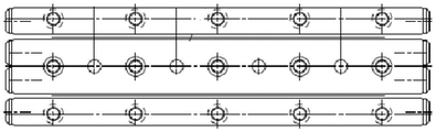
fig. 6 is a schematic view of the guide rail structure of the present invention.
The device comprises a main body supporting seat, a left guide rail plate, a 3 guide rail plate connecting piece, a 4-nut adapter, a 5-guide rail, a 6-right guide rail plate, a 7-screw nut, an 8-screw shaft, a 9-table top, a 10-table top adapter block, an 11-guide rail plate connecting piece, a 12-bolt countersunk head, a 13-bearing, a 14-stroke limiting block and a 15-flexible hinge part.
Detailed Description
The high-precision lifting platform based on the flexible hinge of the invention will be further described in detail with reference to the accompanying drawings and embodiments.
Reference will now be made in detail to embodiments of the present invention, examples of which are illustrated in the accompanying drawings, wherein like or similar reference numerals refer to the same or similar elements or elements having the same or similar function throughout. The embodiments described below with reference to the accompanying drawings are illustrative only for the purpose of explaining the present invention, and are not to be construed as limiting the present invention.
In the description of the present invention, it is to be understood that the terms "central," "longitudinal," "lateral," "upper," "lower," "front," "rear," "left," "right," "vertical," "horizontal," "top," "bottom," "inner," "outer," and the like are used in the orientations and positional relationships indicated in the drawings for convenience in describing the present invention and for simplicity in description, and are not intended to indicate or imply that the referenced devices or elements must have a particular orientation, be constructed and operated in a particular orientation, and are therefore not to be considered limiting. Furthermore, the terms "first" and "second" are used for descriptive purposes only and are not to be construed as indicating or implying relative importance.
In the description of the present invention, it should be noted that, unless otherwise explicitly specified or limited, the terms "mounted," "connected," and "connected" are to be construed broadly, e.g., as meaning either a fixed connection, a removable connection, or an integral connection; can be mechanically or electrically connected; they may be connected directly or indirectly through intervening media, or they may be interconnected between two elements. The specific meanings of the above terms in the present invention can be understood in specific cases to those skilled in the art.
In addition, in the description of the present invention, "a plurality" means two or more unless otherwise specified.
The invention provides a flexible dynamic coupling connection and fixation micrometer positioning platform based on a flexible hinge, which comprises a main body supporting seat 1 for bearing other two parts, wherein the main body supporting seat 1 is fixed with the fixed end of a guide rail 5 through a bolt, the moving end of the guide rail 5 is fixed with a left guide rail plate 2 and a right guide rail plate 6 through bolts, the left guide rail plate 2 and the right guide rail plate 6 are both connected with guide rail plate connecting pieces (3 and 11) through bolts, the guide rail plates are fixedly connected with a nut adapter 4, the nut adapter 4 is connected with a screw nut 7, and the screw nut 7 is matched with a screw shaft 8.
The structure provides power through a screw nut 7 and a screw shaft 8, and guide rails 5 on two sides provide guidance. Five degrees of freedom can be limited by one pair of guide rails 5, so that the guide rail plates move along the vertical direction, but in the moving process, because a contact gap exists between the single pair of guide rails 5, small-amplitude nonparallel is generated, one pair of guide rails 5 is added, the left side guide rail plate 2 is connected with the rear side guide rail plate 6, the moving parallelism of the two pairs of guide rails 5 can be improved through mutual limitation of the plurality of pairs of guide rails 5, and redundant matching is generated, so the guide rail plate connecting pieces (3 and 11) are designed in a flexible hinge mode, and the guide rail plates at two sides can still keep respective parallel moving precision through the deformation of the hinges of the guide rail plate connecting pieces (3 and 11). Ball 7, 8 are in the geometric center of both sides guide rail 5, and the drive power direction coincides with the guide rail 5 in the motion geometry, and nut adaptor 4 adopts flexible hinge structure equally simultaneously, warp through self and enough ensures that drive power is unanimous with the direction of leading, avoids appearing stronger phenomenon.
The specific implementation mode is as follows:
inside as shown in fig. 3, including main part supporting seat 1 for bear all the other each two, the stiff end passes through the bolt fastening in main part supporting seat 1 and the guide rail 5, guide rail 5 removes the end and passes through the bolt fastening with left side guide rail board 2, right side guide rail board 6, left side guide rail board 2, right side guide rail board 6 all are connected through the bolt with guide rail board connecting piece (3, 11), the guide rail links firmly board 3 and nut adaptor 4, nut adaptor 4 is connected with screw nut 7, screw nut 7 and the cooperation of screw shaft 8. As shown in fig. 4, the right rail plate 6 is fixedly connected to a table top adapter block 10, the table top adapter block 10 is fixedly connected to a table top 9, wherein the lifting table needs to provide a customer interface, and the table top 9 mainly provides a user with a fixing interface, and simultaneously plays roles in maintaining the integrity of the product and beautifying the appearance; the table board switching block 10 is used for switching the table board 9 and the guide rail plates on the two sides, and provides an adjusting point for leveling the table board 9 in the later debugging process.
In the assembly engineering, firstly, the guide rail plates on all sides are independently debugged to reach the required parallelism, then the guide rail plate connecting pieces (3 and 11) are connected with the nut adapter piece 4, but are not screwed, firstly, the guide rail plate connecting pieces (3 and 11) are fastened with the guide rail plates on both sides, and then the guide rail plate connecting pieces (3 and 11) and the nut adapter piece 4 are screwed.
The adjustment of the guide rail plates at the two sides is mainly adjusted to the straightness (5 arc seconds) meeting the requirements through an autocollimator, and the parallelism (1 mu m) of the side of the guide rail 5 is detected through a dial indicator on a marble platform, so that the parallelism of the motion axes of the guide rails 5 at the two sides is ensured.
The main body supporting seat 1 firstly passes through the ball screw from a large waist-shaped hole on the upper side in a state that the bearing 13 is not installed, the space for installing the nut adaptor 4 is reserved at the two ends of the ball screw, the nut adaptor 4 is connected with the screw nut 7, and then the bearings 13 on the two sides can be installed.
As shown in fig. 4 and 5, both the two parts include a flexible hinge structure, which can deform in the horizontal direction, in order to improve the linearity and flatness, the arrangement of the two guide rails 5 is adopted, over-positioning exists, if the guide rails 5 on both sides use rigid connection, unstable stress exists, the roller guide rails 5 on both sides cross each other to be stronger, after the structure with the flexible hinge part 15 shown in the figure is adopted, the connecting member can deform a certain amount, the position deviation of the guide rails 5 on both sides in the horizontal direction is self-adapted, meanwhile, the flexible cross-linked structure does not lose the rigidity in the vertical direction, and the load capacity can be well ensured.
The working principle and the process are as follows:
the ball screw is driven to rotate by the stepping motor to drive the screw nut 7 to displace, the screw nut 7 drives the left guide rail plate 2 and the right guide rail plate 6 to displace simultaneously through the nut adapter 4 and the guide rail plate connecting pieces (3 and 11), and the grating reading head feeds back position information to the control system
The ball screw and the screw connection mode in the technical scheme and the conventional structure of the guide rail 5 are the conventional mechanisms, and are not repeated by characters.
It will be evident to those skilled in the art that the invention is not limited to the details of the foregoing illustrative embodiments, and that the present invention may be embodied in other specific forms without departing from the spirit or essential attributes thereof. The present embodiments are therefore to be considered in all respects as illustrative and not restrictive, the scope of the invention being indicated by the appended claims rather than by the foregoing description, and all changes which come within the meaning and range of equivalency of the claims are therefore intended to be embraced therein. Any reference sign in a claim should not be construed as limiting the claim concerned.
Claims (7)
1. A high-precision lifting platform based on a flexible hinge is characterized by comprising a main body supporting seat (1) for bearing other two parts, guide rails (5) for providing guidance are arranged on two sides of the main body supporting seat (1), the fixed ends of the main body supporting seat (1) and the guide rails (5) are fixed through bolts, guide rail plates are arranged on two sides of the main body supporting seat (1), the guide rails (5) on two sides are fixed through bolts, the guide rail plates and the guide rails (5) are pairwise symmetrical to form a rectangle, guide rail plate connecting pieces (3 and 11) are further arranged at one end of the main body supporting seat (1), and the guide rail plate connecting pieces (3 and 11) are perpendicular to the guide rail plates and are connected with the guide rail plates through bolts;
a ball screw and a nut adapter (4) are arranged at the center of the interior of the main body supporting seat (1), the ball screw penetrates through the nut adapter (4), a bearing (13) is arranged at the tail end of the ball screw and connected with the nut adapter, two ends of the nut adapter (4) are connected with guide rail plate connecting pieces (3 and 11) on two sides, the ball screw is positioned at the geometric center of the guide rails (5) on two sides, and the driving force direction is coincident with the motion geometry of the guide rails (5);
the guide rail plate outside still is equipped with mesa switching piece (10) for making level and provide the adjustment point for mesa (9) in the debugging process of convenient later stage, mesa switching piece (10) outside links to each other with mesa (9).
2. The high-precision lifting platform based on the flexible hinge is characterized in that: the position that guide rail plate connecting piece (3, 11) and main part supporting seat (1) contact is equipped with stroke stopper (14), stroke stopper (14) and guide rail plate connecting piece (3, 11) sliding connection.
3. The high-precision lifting platform based on the flexible hinge is characterized in that: two ends of the nut adaptor (4) are provided with flexible hinge parts (15); and both ends of the guide rail plate connecting pieces (3 and 11) are also provided with flexible hinged parts (15).
4. The high-precision lifting platform based on the flexible hinge is characterized in that: the nut adapter piece (4) and the guide rail plate connecting piece (3 and 11) have the same structure.
5. The high-precision lifting platform based on the flexible hinge is characterized in that: the guide rail plate is divided into a left guide rail plate (2) and a right guide rail plate (6), and the left guide rail plate (2) and the right guide rail plate (6) are symmetrically arranged on two sides of the main body supporting seat (1);
the guide rail plate connecting pieces (3 and 11) are also symmetrically arranged and are respectively connected with the left guide rail plate (2) and the right guide rail plate (6).
6. The high-precision lifting platform based on the flexible hinge is characterized in that: the guide rail (5) is a wide-width crossed roller guide rail (5), the two sets are symmetrically arranged in a group, one set is connected with the left guide rail plate (2) and the main body supporting seat (1) through screws, and the other set is connected with the right guide rail plate (6) and the main body supporting seat (1) through screws.
7. The high-precision lifting platform based on the flexible hinge is characterized in that: the ball screw is composed of a screw shaft (8) and a screw nut (7), the screw nut (7) is matched with the screw shaft (8), the lower end of the screw shaft (8) is installed in a bearing (13), and the screw nut (7) is installed at the center of the nut adapter (4).
Priority Applications (1)
| Application Number | Priority Date | Filing Date | Title |
|---|---|---|---|
| CN201811028673.2A CN109140146B (en) | 2018-09-05 | 2018-09-05 | High-precision lifting platform based on flexible hinge |
Applications Claiming Priority (1)
| Application Number | Priority Date | Filing Date | Title |
|---|---|---|---|
| CN201811028673.2A CN109140146B (en) | 2018-09-05 | 2018-09-05 | High-precision lifting platform based on flexible hinge |
Publications (2)
| Publication Number | Publication Date |
|---|---|
| CN109140146A CN109140146A (en) | 2019-01-04 |
| CN109140146B true CN109140146B (en) | 2020-08-18 |
Family
ID=64826740
Family Applications (1)
| Application Number | Title | Priority Date | Filing Date |
|---|---|---|---|
| CN201811028673.2A Active CN109140146B (en) | 2018-09-05 | 2018-09-05 | High-precision lifting platform based on flexible hinge |
Country Status (1)
| Country | Link |
|---|---|
| CN (1) | CN109140146B (en) |
Families Citing this family (2)
| Publication number | Priority date | Publication date | Assignee | Title |
|---|---|---|---|---|
| CN111193914A (en) * | 2020-01-10 | 2020-05-22 | 厦门卓旭智能科技有限公司 | Projector convenient to calibration projection position and good stability |
| CN112096815A (en) * | 2020-08-05 | 2020-12-18 | 广东工业大学 | Novel mechanical guide rail type one-dimensional ball screw motion platform |
Family Cites Families (6)
| Publication number | Priority date | Publication date | Assignee | Title |
|---|---|---|---|---|
| CN102441796B (en) * | 2011-07-08 | 2013-08-07 | 吉林大学 | Ultraprecise piezoelectric stepping rotation driving platform capable of regulating speed mechanically |
| CN104464837B (en) * | 2014-10-31 | 2016-10-05 | 中南大学 | High-precision based on DC motor Driver and three-dimensional motion system |
| CN105485481B (en) * | 2015-12-20 | 2018-01-16 | 华南理工大学 | A kind of displacement adjustable accurate locating platform |
| US10167996B2 (en) * | 2016-02-17 | 2019-01-01 | Tesla, Inc. | Attachment bracket with adjustment mechanisms and pivot |
| CN105666225B (en) * | 2016-04-22 | 2018-02-16 | 清华大学 | A kind of ultraprecise low speed ball-screw straight-line feed device |
| CN107461580B (en) * | 2017-08-31 | 2019-04-23 | 中国科学院光电技术研究所 | A kind of high-precision, high load straight-line displacement platform |
-
2018
- 2018-09-05 CN CN201811028673.2A patent/CN109140146B/en active Active
Also Published As
| Publication number | Publication date |
|---|---|
| CN109140146A (en) | 2019-01-04 |
Similar Documents
| Publication | Publication Date | Title |
|---|---|---|
| CN109140146B (en) | High-precision lifting platform based on flexible hinge | |
| CN103252761A (en) | Long-stroke two-dimensional nano worktable system with angle compensation function | |
| US9504163B2 (en) | Y axis beam positioning system for a PCB drilling machine | |
| CN109373878B (en) | Three-dimensional decoupling type scanning gauge head | |
| WO2022012103A1 (en) | Micro-force measuring type three-dimensional comprehensive thread measuring machine measuring head and measuring method therefor | |
| CN101915562A (en) | Calibrating device for tilt angle sensor | |
| CN109341506B (en) | Three-dimensional displacement measuring device | |
| CN110834914A (en) | Floating type butt joint structure | |
| CN114166458A (en) | Wind tunnel body part suspension system and method | |
| US20140053670A1 (en) | Biaxial linear-motion micro drive apparatus | |
| CN101806687A (en) | Clamp for instrumented indentation testing | |
| CN101382739B (en) | Mini platform device | |
| CN109502542B (en) | Multi-degree-of-freedom nanometer positioning platform based on compliant parallel mechanism | |
| CN109655217A (en) | A kind of beam test beam end support | |
| CN214149232U (en) | Magnetic levitation contact rail body detection platform | |
| CN215469516U (en) | Gantry sliding table flexible hinge support assembly and gantry double-drive device thereof | |
| CN110608963B (en) | Self-coordination fretting fatigue device capable of accurately measuring displacement and friction force and test method | |
| CN113739750A (en) | Airplane control surface measuring device and measuring method | |
| CN217717366U (en) | Hardness meter measuring platform | |
| CN112284313B (en) | High-precision double-measuring-head measuring block comparator | |
| CN214565297U (en) | Steel structure adjusting mechanism for suspension walking shaft | |
| CN108922577A (en) | XY Θ mini positioning platform design based on the non-dead axle detection method of laser ruler | |
| CN213714132U (en) | Positioning structure for axle measuring machine | |
| CN112304267B (en) | Assembling precision adjusting method of high-precision double-measuring-head measuring block comparator | |
| CN116954038B (en) | Movable connecting assembly and macro-micro combined vertical positioning device |
Legal Events
| Date | Code | Title | Description |
|---|---|---|---|
| PB01 | Publication | ||
| PB01 | Publication | ||
| SE01 | Entry into force of request for substantive examination | ||
| SE01 | Entry into force of request for substantive examination | ||
| GR01 | Patent grant | ||
| GR01 | Patent grant |