CN109012944B - Method for measuring aluminum content in aluminum slag - Google Patents
Method for measuring aluminum content in aluminum slag Download PDFInfo
- Publication number
- CN109012944B CN109012944B CN201810944165.2A CN201810944165A CN109012944B CN 109012944 B CN109012944 B CN 109012944B CN 201810944165 A CN201810944165 A CN 201810944165A CN 109012944 B CN109012944 B CN 109012944B
- Authority
- CN
- China
- Prior art keywords
- aluminum
- slag
- aluminum slag
- cutter
- content
- Prior art date
- Legal status (The legal status is an assumption and is not a legal conclusion. Google has not performed a legal analysis and makes no representation as to the accuracy of the status listed.)
- Active
Links
Images


Classifications
-
- B—PERFORMING OPERATIONS; TRANSPORTING
- B02—CRUSHING, PULVERISING, OR DISINTEGRATING; PREPARATORY TREATMENT OF GRAIN FOR MILLING
- B02C—CRUSHING, PULVERISING, OR DISINTEGRATING IN GENERAL; MILLING GRAIN
- B02C18/00—Disintegrating by knives or other cutting or tearing members which chop material into fragments
- B02C18/06—Disintegrating by knives or other cutting or tearing members which chop material into fragments with rotating knives
- B02C18/08—Disintegrating by knives or other cutting or tearing members which chop material into fragments with rotating knives within vertical containers
- B02C18/12—Disintegrating by knives or other cutting or tearing members which chop material into fragments with rotating knives within vertical containers with drive arranged below container
-
- B—PERFORMING OPERATIONS; TRANSPORTING
- B02—CRUSHING, PULVERISING, OR DISINTEGRATING; PREPARATORY TREATMENT OF GRAIN FOR MILLING
- B02C—CRUSHING, PULVERISING, OR DISINTEGRATING IN GENERAL; MILLING GRAIN
- B02C23/00—Auxiliary methods or auxiliary devices or accessories specially adapted for crushing or disintegrating not provided for in preceding groups or not specially adapted to apparatus covered by a single preceding group
- B02C23/08—Separating or sorting of material, associated with crushing or disintegrating
- B02C23/16—Separating or sorting of material, associated with crushing or disintegrating with separator defining termination of crushing or disintegrating zone, e.g. screen denying egress of oversize material
-
- G—PHYSICS
- G01—MEASURING; TESTING
- G01N—INVESTIGATING OR ANALYSING MATERIALS BY DETERMINING THEIR CHEMICAL OR PHYSICAL PROPERTIES
- G01N1/00—Sampling; Preparing specimens for investigation
- G01N1/28—Preparing specimens for investigation including physical details of (bio-)chemical methods covered elsewhere, e.g. G01N33/50, C12Q
- G01N1/286—Preparing specimens for investigation including physical details of (bio-)chemical methods covered elsewhere, e.g. G01N33/50, C12Q involving mechanical work, e.g. chopping, disintegrating, compacting, homogenising
-
- G—PHYSICS
- G01—MEASURING; TESTING
- G01N—INVESTIGATING OR ANALYSING MATERIALS BY DETERMINING THEIR CHEMICAL OR PHYSICAL PROPERTIES
- G01N5/00—Analysing materials by weighing, e.g. weighing small particles separated from a gas or liquid
-
- B—PERFORMING OPERATIONS; TRANSPORTING
- B02—CRUSHING, PULVERISING, OR DISINTEGRATING; PREPARATORY TREATMENT OF GRAIN FOR MILLING
- B02C—CRUSHING, PULVERISING, OR DISINTEGRATING IN GENERAL; MILLING GRAIN
- B02C23/00—Auxiliary methods or auxiliary devices or accessories specially adapted for crushing or disintegrating not provided for in preceding groups or not specially adapted to apparatus covered by a single preceding group
- B02C23/08—Separating or sorting of material, associated with crushing or disintegrating
- B02C23/16—Separating or sorting of material, associated with crushing or disintegrating with separator defining termination of crushing or disintegrating zone, e.g. screen denying egress of oversize material
- B02C2023/165—Screen denying egress of oversize material
Abstract
The invention relates to the technical field of aluminum content determination, and relates to a method for determining the aluminum content in aluminum slag, which has the technical scheme that: a method for measuring the content of aluminum in aluminum slag comprises the following steps: obtaining high-temperature aluminum slag in a smelting furnace; cooling the aluminum slag in a high-temperature state; crushing the cooled aluminum slag; screening the crushed aluminum slag to separate out aluminum; and calculating the content of the aluminum in the unit aluminum slag according to the total weight of the aluminum slag and the weight of the aluminum separated from the aluminum slag. Compared with the chemical measurement mode in the prior art, the technical scheme of the invention carries out cooling, crushing and screening operations on the aluminum slag in a physical mode, further obtains the content of aluminum in unit aluminum slag by weighing and calculating, and has relatively high operation safety because no chemical reagent is needed.
Description
Technical Field
The invention relates to the technical field of determination of aluminum content in aluminum slag, in particular to a method for determining the aluminum content in the aluminum slag.
Background
At present, the method for measuring the content of aluminum in aluminum slag is a chemical measurement method, chemical articles such as an oxidant or a ferric chloride-ammonium chloride mixed solution are needed, the content of aluminum is indirectly calculated by measuring the volume of a used reagent or the article when the content of aluminum is calculated, the process is complex, and a professional is needed to operate. And the operation safety is also poor due to the need of using chemical reagents.
Therefore, it is urgently required to design a new assay method which is convenient to operate and has high safety.
Disclosure of Invention
In view of the above, the invention provides a method for measuring the aluminum content in aluminum slag, and mainly aims to solve the technical problem of low safety caused by the need of using a chemical reagent when the aluminum content in the aluminum slag is measured by using a chemical measurement method in the prior art.
In order to achieve the purpose, the invention mainly provides the following technical scheme:
the embodiment of the invention provides a method for measuring the content of aluminum in aluminum slag, which comprises the following steps:
step S1: obtaining high-temperature aluminum slag in a smelting furnace;
step S2: cooling the aluminum slag in a high-temperature state;
step S3: crushing the cooled aluminum slag;
step S4: screening the crushed aluminum slag to separate out aluminum;
step S5: and calculating the content of the aluminum in the unit aluminum slag according to the total weight of the aluminum slag and the weight of the aluminum separated from the aluminum slag.
By adopting the technical scheme, compared with a chemical measurement mode in the prior art, the technical scheme provided by the invention has the advantages that the aluminum slag is cooled, crushed and screened in a physical mode, the aluminum content in the unit aluminum slag is obtained by weighing and calculating, and a chemical reagent is not required, so that the operation safety is relatively high.
In addition, compared with a chemical determination method, the technical scheme of the invention adopts a physical determination mode, so that the operation of ordinary operators is only needed, and the implementation is relatively convenient.
The invention is further configured to: the total weight of the aluminum dross in step S5 is determined by adding the weight of the separated aluminum to the weight of impurities other than aluminum.
With the above arrangement, after the screening of step S4, aluminum and other impurities can be separated from the aluminum dross. The separated aluminum and other impurities were then weighed separately to give a weight of separated aluminum of m2 and a weight of other impurities of m 3. Then m2+ m3 is the total weight m1 of the aluminum dross.
The invention is further configured to: cooling the aluminum dross in a high-temperature state by using an aluminum dross cooler in step S2;
the aluminum slag cooler comprises a vacuumizing device and a sealed container for containing aluminum slag;
and the vacuumizing device is used for vacuumizing the inside of the sealed container so as to cool the aluminum slag in the sealed container.
Through foretell setting, evacuating device can be to the inside evacuation of sealed container to take out the high temperature air in the sealed container, make the high temperature aluminium sediment quick cooling in the sealed container, thereby realize the effect to aluminium sediment cooling treatment.
The invention is further configured to: the vacuum pumping device comprises an exhaust fan and an exhaust pipe;
one end of the exhaust pipe is communicated with the inside of the sealed container, and the other end of the exhaust pipe is communicated with an exhaust opening of the exhaust fan;
and the exhaust fan is used for vacuumizing the inside of the sealed container through the exhaust pipe so as to cool the aluminum slag in the sealed container.
Wherein, through the cooperation of air exhauster and exhaust column to the inside evacuation of sealed container, its structure is simple relatively, and it is more convenient to implement.
The invention is further configured to: the sealed container comprises a sealing disc and a sealing cover covered on the sealing disc;
an accommodating space for accommodating aluminum slag is formed between the sealing disc and the sealing cover.
Through foretell setting, divide into the sealed container and seal the dish and the closing cap is processed, and it is relatively more convenient to process.
The invention is further configured to: crushing the cooled aluminum slag by using an aluminum slag crusher in step S3;
the aluminum slag crusher comprises a first driving mechanism, a cutter, a screening structure and a crushing cavity for containing aluminum slag;
the cutter is arranged in the crushing cavity;
the driving mechanism is used for driving the cutter to rotate so as to break the aluminum slag in the crushing cavity;
the side wall of the crushing cavity is provided with a slag discharge hole corresponding to the cutter, and the screening structure is arranged at the slag discharge hole, so that the aluminum slag meeting the granularity requirement in the crushing cavity is thrown out of the slag discharge hole through the screening structure under the driving of the cutter.
Through adopting above-mentioned technical scheme, when the cutter high-speed rotation, the aluminium sediment in broken intracavity is got rid of to the screening structure in the effect of centrifugal force, is struck to enough hours by the cutter when the aluminium sediment and just can pass the screening structure and discharge from the mud hole.
The invention is further configured to: the aluminum slag crusher also comprises a main body and an end cover;
the crushing device comprises a main body, an end cover and a crushing cavity, wherein the main body is hollow, one end of the main body is open, the end cover is covered on the opening at one end of the main body, and the crushing cavity is formed between the main body and the end cover.
The crushing cavity is formed by matching the end cover with the main body, the structure is relatively simple, and the implementation is convenient.
The invention is further configured to: the aluminum slag crusher also comprises an annular lining plate;
the lining plate is sleeved on the inner wall of the crushing cavity, and a through hole opposite to the slag discharge hole is formed in the lining plate;
the inner wall of the lining plate is provided with a wear-resistant structure so as to be matched with the cutter to crush the aluminum slag.
Wherein, through the welt that sets up, can prevent that the aluminium sediment from directly rubbing with the inner wall in broken chamber and leading to broken chamber to take place to damage, improved the life in broken chamber.
The invention is further configured to: screening the crushed aluminum slag by using a screening device in step S4 to separate aluminum;
the screening device comprises a screen and a second driving mechanism;
and the second driving mechanism is used for driving the screen to vibrate so as to screen the crushed aluminum slag.
Through adopting above-mentioned technical scheme, screening plant can sieve the aluminium sediment after the crushing treatment.
The invention is further configured to: the screening device further comprises a housing;
the shell is hollow and one end of the shell is open;
the screen is arranged in the shell, and an accommodating cavity is formed between the screen and the bottom of the shell;
the second driving mechanism is connected with the shell so as to drive the screen to vibrate through the shell.
Through the arrangement, other impurities in powder form are separated into the accommodating cavity, and the granular or flaky aluminum is left on the screen. In addition, the second driving mechanism drives the screen to vibrate through the shell, so that the screen can be prevented from being damaged due to direct connection with the screen.
By means of the technical scheme, the method for measuring the aluminum content in the aluminum slag has the following beneficial effects:
compared with the chemical measurement mode in the prior art, the technical scheme provided by the invention has the advantages that the cooling, smashing and screening operations are carried out on the aluminum slag in a physical mode, the content of aluminum in unit aluminum slag is obtained through weighing and calculation, and the operation safety is relatively high because no chemical reagent is needed.
In addition, compared with a chemical determination method, the technical scheme of the invention adopts a physical determination mode, so that the operation of ordinary operators is only needed, and the implementation is relatively convenient.
The foregoing description is only an overview of the technical solutions of the present invention, and in order to make the technical solutions of the present invention more clearly understood and to implement them in accordance with the contents of the description, the following detailed description is given with reference to the preferred embodiments of the present invention and the accompanying drawings.
Drawings
FIG. 1 is a block flow diagram of a method for measuring the aluminum content in aluminum slag according to an embodiment of the present invention;
FIG. 2 is a schematic structural diagram of an aluminum dross cooler according to an embodiment of the invention;
FIG. 3 is a schematic view of a part of the internal structure of an aluminum dross cooler according to an embodiment of the invention;
FIG. 4 is a schematic structural view of a slag cooler according to an embodiment of the present invention after a cover is hidden;
FIG. 5 is a schematic structural diagram of an aluminum slag crusher according to an embodiment of the present invention;
FIG. 6 is a schematic cross-sectional view of an aluminum slag crusher according to an embodiment of the present invention;
FIG. 7 is a schematic structural diagram of an aluminum slag crusher according to an embodiment of the present invention, after hiding end covers and a funnel;
FIG. 8 is a first perspective view of a tool holder according to an embodiment of the present invention;
FIG. 9 is a second perspective view of a tool holder according to an embodiment of the present invention;
FIG. 10 is a schematic view of a main body according to a first perspective structure of the present invention;
FIG. 11 is a schematic diagram illustrating a second perspective structure of a main body according to an embodiment of the present invention;
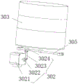
FIG. 12 is a schematic diagram of a screening device according to an embodiment of the present invention;
figure 13 is a schematic view of a hidden frame of a screening device according to an embodiment of the present invention.
Reference numerals: 1. a first drive mechanism; 2. a cutter; 3. screening the structure; 31. an orifice plate; 4. a crushing chamber; 41. A main body; 42. an end cap; 421. a feed inlet; 43. a convex column; 431. a recessed groove; 432. a first via hole; 400. a slag discharge hole; 5. a tool apron; 6. a first motor; 61. an output shaft; 7. a connector; 8. a funnel; 9. a liner plate; 91. a second via hole; 92. a wear resistant structure; 200. an aluminum slag crusher; 10. a vacuum pumping device; 101. an exhaust fan; 102. an exhaust pipe; 1021. A U-shaped structure; 20. sealing the container; 201. sealing the disc; 202. sealing the cover; 30. a fan; 40. a slag pan; 401. a separator structure; 4011. a communicating groove; 402. an aluminum slag accommodating groove; 50. a vehicle body; 100. an aluminum slag cooler; 300. a screening device; 301. screening a screen; 302. a second drive mechanism; 3021. a second motor; 3022. a disc; 3023. a first link; 3024. A second link; 303. a housing; 304. a frame; 305. a rotating shaft.
Detailed Description
To further explain the technical means and effects of the present invention adopted to achieve the predetermined object, the following detailed description of the embodiments, structures, features and effects according to the present invention will be made with reference to the accompanying drawings and preferred embodiments. In the following description, different "one embodiment" or "an embodiment" refers to not necessarily the same embodiment. Furthermore, the particular features, structures, or characteristics may be combined in any suitable manner in one or more embodiments.
As shown in fig. 1, an embodiment of the present invention provides a method for determining an aluminum content in aluminum slag, which includes the following steps:
step S1: and obtaining the high-temperature aluminum slag in the aluminum smelting furnace.
Step S2: and cooling the aluminum slag in a high-temperature state.
Step S3: and crushing the cooled aluminum slag.
When the aluminum slag is smashed, for example, the aluminum slag is smashed, the aluminum is granular or flaky after being smashed due to the high ductility of the aluminum. While other impurities such as stones and the like are pulverized.
Step S4: screening the crushed aluminum slag to separate out aluminum;
because the aluminum in the aluminum slag is in a granular or flaky shape after being smashed, and other impurities such as stones are in a powdery shape, the aluminum can be easily separated from the smashed slag body.
Step S5: and calculating the content of the aluminum in the unit aluminum slag according to the total weight of the aluminum slag and the weight of the aluminum separated from the aluminum slag.
Wherein the total weight of the aluminum slag is m1, and the weight of the separated aluminum is m 2. Wherein the content of aluminum in the unit aluminum slag is obtained by dividing m2 by m 1.
In the technical scheme provided by the invention, compared with a chemical measurement mode in the prior art, the aluminum slag is cooled, smashed and screened in a physical mode, the aluminum content in unit aluminum slag is obtained through weighing and calculation, and a chemical reagent is not needed, so that the operation safety is relatively high.
In addition, compared with a chemical determination method, the technical scheme of the invention adopts a physical determination mode, so that the operation of ordinary operators is only needed, and the implementation is relatively convenient.
Further, the total weight of the aluminum dross in the step S5 may be obtained by adding the weight of the separated aluminum to the weight of impurities other than aluminum.
Specifically, after the screening of step S4, aluminum and other impurities may be separated from the aluminum dross. The separated aluminum and other impurities were then weighed separately to give a weight of separated aluminum of m2 and a weight of other impurities of m 3. Then m2+ m3 is the total weight m1 of the aluminum dross.
Of course, in other embodiments, the weight m1 of the aluminum dross can be directly weighed. For example, the high-temperature aluminum slag taken out of the smelting furnace can be directly weighed to obtain the total weight m1 of the aluminum slag; or weighing the cooled aluminum slag to obtain the total weight m1 of the aluminum slag; or directly weighing the aluminum slag after the crushing treatment to obtain the total weight m1 of the aluminum slag. Wherein, all can obtain the total weight of aluminium sediment through foretell mode, specifically choose for use which kind of mode, can select according to actual conditions, no longer repeated here.
Further, in the above step S2, the aluminum dross cooler 100 may be used to cool the aluminum dross in a high temperature state.
As shown in fig. 2 and 3, the above-described dross cooler 100 may include a vacuum extractor 10 and a sealed container 20. The sealed container 20 is used for containing aluminum dross. The vacuum extractor 10 is used for evacuating the inside of the sealed container 20 to cool the aluminum dross in the sealed container 20.
Through the arrangement, the vacuumizing device 10 can vacuumize the inside of the sealed container 20 to pump out high-temperature air in the sealed container 20, so that high-temperature aluminum slag in the sealed container 20 is rapidly cooled, and the effect of cooling the aluminum slag is achieved.
In addition, the air in the sealed container 20 is pumped away through the vacuum pumping device 10, so that the chemical reaction between the aluminum in the aluminum slag and the oxygen in the air can be prevented, and the influence on the calculation precision of the aluminum content in the subsequent aluminum slag is avoided.
Further, as shown in fig. 2 and 3, the aforementioned vacuum device 10 may include a suction fan 101 and an exhaust pipe 102. One end of the suction pipe 102 communicates with the inside of the hermetic container 20, and the other end communicates with the suction opening of the suction fan 101. The exhaust fan 101 evacuates the inside of the sealed container 20 through the exhaust pipe 102 to cool the aluminum dross in the sealed container 20. Wherein, the interior of the sealed container 20 is vacuumized by the matching of the exhaust fan 101 and the exhaust pipe 102, the structure is relatively simple, and the implementation is more convenient.
The aforementioned exhaust pipe 102 may be a heat dissipation pipe, such as a copper pipe, an aluminum pipe, or an iron pipe. As shown in fig. 3, the exhaust duct 102 further has a U-shaped structure 1021 connected in sequence to assist heat dissipation, so as to prevent the overheated air from being drawn into the exhaust fan 101 to affect the service life of the exhaust fan 101.
The U-shaped structures 1021 connected in sequence form a corrugated structure, so that the heat dissipation area of the exhaust pipe 102 can be increased, and the heat dissipation efficiency can be improved.
Further, the aluminum dross cooler 100 may further include a heat sink. The heat dissipation device is used for dissipating heat of the exhaust duct 102.
The heat dissipation device can further assist the heat dissipation of the heat dissipation pipe, and further prevent the overheated air from being drawn into the exhaust fan 101 to affect the service life of the exhaust fan 101.
Further, as shown in fig. 3, the heat dissipation device may include a fan 30 to dissipate heat of the exhaust pipe 102 through the fan 30. Wherein, the fan 30 is a commercially available part, and is convenient to acquire and implement.
As shown in fig. 3, the number of the fans 30 may be two or more, so as to further improve the heat dissipation efficiency of the exhaust pipe 102.
In one example, as shown in fig. 2 and 3, the aforementioned sealed container 20 may include a cover plate 201 and a cover 202. The cover 202 covers the sealing plate 201. An accommodating space for accommodating aluminum dross is formed between the sealing plate 201 and the sealing cover 202.
By the arrangement, the sealed container 20 is divided into the sealing disc 201 and the sealing cover 202 for processing, and the processing is relatively convenient.
Furthermore, the sealing disc 201 and the sealing cover 202 can be connected through a flange, so that the sealing disc 201 and the sealing cover 202 can be relatively detached on one hand, and aluminum slag can be conveniently taken and placed; on the other hand, the sealing effect of the connection between the two can also be improved.
Further, the aforementioned cover 202 may have a transparent window thereon, so as to facilitate the operator to observe the cooling condition of the aluminum dross through the transparent window.
The transparent observation window can be made of toughened glass.
Further, as shown in fig. 4, the aluminum slag cooler 100 may further include a slag pan 40. A slag pan 40 is located inside the sealed container 20. The sealed container 20 contains aluminum dross through a dross pan 40.
The slag pan 40 may be made of a high temperature resistant material. And the slag tray 40 is used for containing the aluminum slag, so that the service life of the sealed container 20 can be prolonged, and the damage to the sealed container 20 caused by directly placing the high-temperature aluminum slag on the sealed container 20 can be prevented.
Further, as shown in fig. 4, the above-mentioned aluminum dross cooler 100 may further include a partition structure 401. The partition plate structure 401 is disposed inside the slag pan 40, and divides two or more aluminum slag accommodating grooves 402 inside the slag pan 40. Wherein, the upper end of baffle structure 401 is equipped with intercommunication groove 4011 to each aluminium sediment holding tank 402 of intercommunication.
The intercommunication groove 4011 that above-mentioned set up can make the aluminium sediment that is thick form in each aluminium sediment holding tank 402 flow each other to make the distribution of aluminium sediment in each aluminium sediment holding tank 402 more even, can improve the cooling efficiency of aluminium sediment.
Further, as shown in fig. 2 to 4, the aluminum dross cooler 100 may further include a vehicle body 50. The vehicle body 50 is used for carrying the vacuum extractor 10 and the sealed container 20. The aluminum dross cooler 100 can be moved by the carriage body 50, thus facilitating handling.
Further, in the above step S3, the cooled aluminum dross may be crushed by using the aluminum dross crusher 200.
As shown in fig. 5 to 7, the above-described dross crusher 200 may comprise a first drive mechanism 1, a cutter 2, a screening structure 3 and a crushing chamber 4. The crushing cavity 4 is used for containing the cooled aluminum slag. The tool 2 is arranged in the crushing chamber 4. The first driving mechanism 1 is used for driving the cutter 2 to rotate so as to break the aluminum slag in the crushing cavity 4. The side wall of the crushing chamber 4 is provided with a slag discharge hole 400 corresponding to the cutter 2. The screening structure 3 is arranged at the position of the slag discharge hole 400, so that the aluminum slag meeting the granularity requirement in the crushing cavity 4 is thrown out of the slag discharge hole 400 through the screening structure 3 under the driving of the cutter 2. The term "meeting the requirement for the particle size" used herein means meeting the requirement for the particle size of the screening structure 3, and the aluminum slag can pass through the screening structure 3 and enter the slag discharge hole 400 only if the requirement for the particle size of the screening structure 3 is met; and the aluminum slag which does not meet the granularity requirement is continuously smashed in the smashing cavity 4 until all the aluminum slag in the smashing cavity 4 is smashed to meet the granularity requirement of the screening structure 3, and then all the aluminum slag passes through the screening structure 3 and is discharged from the slag discharge hole 400.
Specifically, when the cutter 2 rotates at a high speed, the aluminum slag in the crushing cavity 4 is thrown to the screening structure 3 under the action of centrifugal force, and when the aluminum slag is cut by the cutter 2 and is small enough, the aluminum slag can pass through the screening structure 3 and be discharged from the slag discharge hole 400.
Here, it should be noted that: due to the high ductility of aluminum, aluminum is in the form of particles or flakes after being broken. While other impurities such as stones and the like are pulverized. After the aluminum slag is crushed by the aluminum slag crusher 200, the aluminum slag can be separated from the slag body in a granular or sheet form by screening.
Further, as shown in fig. 5 and 6, the above-mentioned slag crusher 200 may further include a main body 41 and an end cap 42. The main body 41 is hollow inside and open at one end. The end cap 42 covers the opening of the main body 41. Between the body 41 and the end cap 42 the aforementioned crushing chamber 4 is formed. In this example, the crushing chamber 4 is formed by means of the end cap 42 cooperating with the body 41, which is relatively simple in construction and convenient to implement.
As shown in fig. 6 to 9, the aluminum slag crusher 200 may further include a tool holder 5. The tool 2 described above is mounted on a holder 5. The first driving mechanism 1 is used for driving the tool holder 5 to rotate, so as to drive the tool 2 to rotate through the tool holder 5. In this example, with the provision of the tool holder 5, it is possible to prevent the first drive mechanism 1 from directly driving the tool 2 with possible damage to the tool 2.
As shown in fig. 6 and 7, the first driving mechanism 1 may include a first motor 6 to drive the tool holder 5 to rotate by the first motor 6. Wherein, first motor 6 is the market-purchased piece, and it is all convenient to acquire and implement.
Further, as shown in fig. 10 and 11, an end of the main body 41 facing away from the end cap 42 has a convex pillar 43 formed inside the main body 41 in an inward recessed manner, and a concave groove 431 is formed inside the convex pillar 43. The tool seat 5 is rotatably sleeved on the convex post 43. The bottom of the recess groove 431 has a first via 432. The output shaft 61 of the first motor 6 is connected to the tool holder 5 through a first via 432 to drive the tool holder 5 to rotate.
Through the arrangement, the first motor 6 can drive the cutter holder 5 to rotate, and the operation is relatively convenient.
Further, as shown in fig. 6, the aforesaid aluminum slag crusher 200 may further include a connector 7. The output shaft 61 of the first motor 6 is connected to one end of the connector 7, and the other end of the connector 7 is connected to the tool post 5 through the first via 432, so that the output shaft 61 of the first motor 6 is connected to the tool post 5 through the connector 7. In this example, by providing the coupling head 7, the inconvenience of the output shaft 61 of the first motor 6 being directly coupled to the holder 5 is avoided.
Further, as shown in fig. 5 and 6, the end cap 42 may be provided with a feed port 421. The aluminum slag crusher 200 may further include a hopper 8 connected to the feed port 421 to feed the feed port 421 through the hopper 8. In this example, with the hopper 8 provided, there is a technical effect of facilitating the feeding.
Further, as shown in fig. 7, the aforesaid aluminum dross crusher 200 may further include a lining plate 9. The lining plate 9 is annular. The lining plate 9 is sleeved on the inner wall of the crushing cavity 4. The lining plate 9 is provided with a second through hole 91 opposite to the slag discharge hole 400. The inner wall of the lining plate 9 is provided with a wear-resistant structure 92 so as to be matched with the cutter 2 to crush the aluminum slag. In this example, through the welt 9 that sets up, can prevent that the aluminium sediment from directly rubbing with the inner wall in broken chamber 4 and leading to broken chamber 4 to take place to damage, improved the life in broken chamber 4.
In one example, the wear-resistant structure 92 may be a V-shaped structure sequentially connected along the circumference of the lining plate 9, which is relatively convenient to machine.
Further, as shown in fig. 7, the aforementioned screening structure 3 may comprise an orifice 31. The screening structure 3 screens the aluminum slag flowing into the slag discharge hole 400 through the pore plate 31, so that the aluminum slag can be discharged from the slag discharge hole 400 only when the aluminum slag is smashed to meet the requirement of the particle size of the pore plate 31; otherwise, the aluminium dross needs to be crushed further in the crushing chamber 4.
Further, in the step S4, the crushed aluminum dross may be separated by screening using the screening device 300.
As shown in fig. 12 and 13, the aforementioned screening device 300 may include a screen 301 and a second driving mechanism 302. The second driving mechanism 302 is used for driving the screen 301 to vibrate so as to screen the crushed aluminum slag.
Due to the high ductility of aluminum, aluminum is in the form of particles or flakes after being broken. While other impurities such as stones and the like are pulverized. The crushed aluminum slag is placed on a screen 301, and granular or flaky aluminum can be separated from other powdery impurities by the vibration of the screen 301.
As shown in fig. 12 and 13, the aforementioned screening device 300 may further include a housing 303. The interior of the housing 303 is hollow and open at one end. The screen 301 is disposed within the housing 303 and forms a receiving cavity with the bottom of the housing 303. The aforementioned second driving mechanism 302 is connected to the housing 303 to drive the screen 301 to vibrate through the housing 303.
With the above arrangement, other impurities in powder form are separated into the accommodating chamber, and the aluminum in granular or flake form remains on the mesh 301. In addition, the second driving mechanism 302 drives the screen 301 to vibrate through the housing 303, so that the screen 301 can be prevented from being damaged due to direct connection with the screen 301.
As shown in fig. 12, the screening device 300 may include a frame 304, and the housing 303 may be rotatably disposed on the frame 304. The second driving mechanism 302 is configured to drive the housing 303 to swing on the frame 304, so that the housing 303 vibrates.
Preferably, as shown in fig. 13, the second driving mechanism 302 may be a crank mechanism. That is, the second driving mechanism 302 includes a second motor 3021, a circular disk 3022, a first link 3023, and a second link 3024. An output shaft 61 of the second motor 3021 is connected to the disc 3022 to drive the disc 3022 in rotation. One end of the first link 3023 is hinged to the disc 3022, the other end is hinged to one end of the second link 3024, and the other end of the second link 3024 is connected to the housing 303.
When the second motor 3021 is started, the output shaft 61 of the second motor 3021 drives the disc 3022 to rotate, and the disc 3022 drives the shell 303 to swing through the first connecting rod 3023 and the second connecting rod 3024, so that the screen 301 in the shell 303 vibrates, and the crushed aluminum slag is screened and separated.
As shown in fig. 13, in order to achieve the technical effect that the housing 303 can rotate relative to the frame 304, a rotating shaft 305 may be disposed on the frame 304, and a connecting block having a shaft hole adapted to the rotating shaft 305 may be disposed on the housing 303. The rotation shaft 305 is fitted in a shaft hole of the connection block so that the housing 303 can be rotated by the rotation shaft 305.
Further, in order to improve the sieving effect, it is preferable that the number of the sieves 301 is two or more, and the sieves are sequentially provided at intervals to sieve the aluminum dross a plurality of times.
Here, it should be noted that: in the case of no conflict, a person skilled in the art may combine the related technical features in the above examples according to actual situations to achieve corresponding technical effects, and details of various combining situations are not described herein.
The above description is only a preferred embodiment of the present invention, and the protection scope of the present invention is not limited to the above embodiments, and all technical solutions belonging to the idea of the present invention belong to the protection scope of the present invention. It should be noted that modifications and embellishments within the scope of the invention may occur to those skilled in the art without departing from the principle of the invention, and are considered to be within the scope of the invention.
Claims (9)
1. The method for measuring the aluminum content in the aluminum slag is characterized by comprising the following steps:
step S1: obtaining high-temperature aluminum slag in a smelting furnace;
step S2: cooling the aluminum slag in a high-temperature state;
step S3: crushing the cooled aluminum slag;
step S4: screening the crushed aluminum slag to separate out aluminum;
step S5: calculating the content of aluminum in the unit aluminum slag according to the total weight of the aluminum slag and the weight of the aluminum separated from the aluminum slag;
wherein, in step S2, the aluminum slag in high temperature state is cooled by using an aluminum slag cooler (100); the aluminum slag cooler (100) comprises a vacuumizing device (10) and a sealed container (20) for containing aluminum slag; the vacuumizing device (10) is used for vacuumizing the inside of the sealed container (20) to cool the aluminum slag in the sealed container (20);
crushing the cooled aluminum dross by using an aluminum dross crusher (200) in step S3; the aluminum slag crusher (200) comprises a first driving mechanism (1), a cutter (2), a cutter holder (5) and a crushing cavity (4) for containing aluminum slag, wherein the cutter (2) is arranged in the crushing cavity (4), the cutter (2) is installed on the cutter holder (5), and the first driving mechanism is used for driving the cutter holder (5) to rotate so as to drive the cutter (2) to rotate through the cutter holder (5) and crush the aluminum slag in the crushing cavity (4); the cutter holder (5) is provided with an annular side wall, a connecting plate extending along the radial direction is arranged on the side wall of the cutter holder (5), the cutter (2) is sheet-shaped, and one end of the cutter (2) is opposite to the connecting plate and is connected to the connecting plate.
2. The method as claimed in claim 1, wherein the total weight of the aluminum dross in step S5 is determined by adding the weight of the separated aluminum to the weight of impurities other than aluminum.
3. The method for measuring the aluminum content in the aluminum slag according to claim 1, wherein the vacuum extractor (10) comprises an exhaust fan (101) and an exhaust pipe (102);
one end of the exhaust pipe (102) is communicated with the inside of the sealed container (20), and the other end of the exhaust pipe is communicated with an exhaust opening of the exhaust fan (101);
the exhaust fan (101) is used for vacuumizing the inside of the sealed container (20) through the exhaust pipe (102) so as to cool the aluminum slag in the sealed container (20).
4. The method for measuring the aluminum content in the aluminum slag according to claim 1,
the sealed container (20) comprises a sealing disc (201) and a sealing cover (202) covered on the sealing disc (201);
an accommodating space for accommodating aluminum dross is formed between the sealing disc (201) and the sealing cover (202).
5. The method of measuring an aluminum content in an aluminum slag according to any one of claims 1 to 4,
the aluminum slag crusher (200) comprises a screening structure (3);
have on the lateral wall of broken chamber (4) with corresponding row's cinder hole (400) of cutter (2), screening structure (3) set up arrange cinder hole (400) department, make the aluminium sediment that accords with the granularity requirement in broken chamber (4) throw away through screening structure (3) under the drive of cutter (2) row cinder hole (400).
6. The method for measuring the aluminum content in the aluminum slag according to claim 5,
the aluminum slag crusher (200) further comprises a main body (41) and an end cover (42);
the crushing chamber is characterized in that the main body (41) is hollow and is provided with an opening at one end, the end cover (42) covers the opening at one end of the main body (41), and the crushing chamber (4) is formed between the main body (41) and the end cover (42).
7. The method for measuring the aluminum content in the aluminum slag according to claim 5,
the aluminum slag crusher (200) also comprises an annular lining plate (9);
the lining plate (9) is sleeved on the inner wall of the crushing cavity (4), and a through hole opposite to the slag discharge hole (400) is formed in the lining plate (9);
and the inner wall of the lining plate (9) is provided with a wear-resistant structure (92) so as to be matched with the cutter (2) to crush the aluminum slag.
8. The method of measuring the aluminum content in the aluminum slag according to any one of claims 1 to 4, 6 and 7,
screening the crushed aluminum slag by using a screening device (300) in step S4 to separate aluminum;
the screening device (300) comprises a screen (301) and a second drive mechanism (302);
the second driving mechanism (302) is used for driving the screen (301) to vibrate so as to screen the crushed aluminum slag.
9. The method for measuring the aluminum content in the aluminum slag according to claim 8,
the screening device (300) further comprises a housing (303);
the shell (303) is hollow and has an opening at one end;
the screen (301) is arranged in the shell (303) and forms an accommodating cavity with the bottom of the shell (303);
the second driving mechanism (302) is connected with the shell (303) so as to drive the screen (301) to vibrate through the shell (303).
Priority Applications (1)
| Application Number | Priority Date | Filing Date | Title |
|---|---|---|---|
| CN201810944165.2A CN109012944B (en) | 2018-08-18 | 2018-08-18 | Method for measuring aluminum content in aluminum slag |
Applications Claiming Priority (1)
| Application Number | Priority Date | Filing Date | Title |
|---|---|---|---|
| CN201810944165.2A CN109012944B (en) | 2018-08-18 | 2018-08-18 | Method for measuring aluminum content in aluminum slag |
Publications (2)
| Publication Number | Publication Date |
|---|---|
| CN109012944A CN109012944A (en) | 2018-12-18 |
| CN109012944B true CN109012944B (en) | 2020-12-04 |
Family
ID=64631960
Family Applications (1)
| Application Number | Title | Priority Date | Filing Date |
|---|---|---|---|
| CN201810944165.2A Active CN109012944B (en) | 2018-08-18 | 2018-08-18 | Method for measuring aluminum content in aluminum slag |
Country Status (1)
| Country | Link |
|---|---|
| CN (1) | CN109012944B (en) |
Citations (14)
| Publication number | Priority date | Publication date | Assignee | Title |
|---|---|---|---|---|
| US4243640A (en) * | 1978-05-23 | 1981-01-06 | Hill Robert O | Process of extraction of aluminum values from coal ash |
| CN1903725A (en) * | 2006-08-08 | 2007-01-31 | 上海添诚商务发展有限公司 | Comprehensive utilization treatment tachnology of aluminium waste slag, waste ash |
| CN201093875Y (en) * | 2007-08-21 | 2008-07-30 | 张建运 | Vacuum rapid hardening stove draught fan air stiring device |
| CN201260976Y (en) * | 2008-08-18 | 2009-06-24 | 天津市人维科技发展有限公司 | Aluminum slag-crushing device |
| CN201476590U (en) * | 2009-03-05 | 2010-05-19 | 胡志豪 | Aluminum slag cooling machine |
| CN101892393A (en) * | 2010-07-30 | 2010-11-24 | 湖南创元铝业有限公司 | Process for separating metallic aluminum |
| CN103212535A (en) * | 2013-04-27 | 2013-07-24 | 华南理工大学 | Powder vibrating screening machine |
| CN104028339A (en) * | 2014-05-21 | 2014-09-10 | 成都中牧生物药业有限公司 | Smashing mechanism beneficial to medicine material smashing efficiency |
| CN204594831U (en) * | 2015-05-11 | 2015-08-26 | 河北立中有色金属集团有限公司 | A kind of device detecting metal aluminum content in aluminium ash |
| CN204911747U (en) * | 2015-07-07 | 2015-12-30 | 苏州卡迪亚铝业有限公司 | Special screening plant of aluminium ash |
| CN105689099A (en) * | 2016-03-04 | 2016-06-22 | 苏州华冲精密机械有限公司 | Aluminum ash separating device |
| CN106399693A (en) * | 2016-10-08 | 2017-02-15 | 淄博海慧工程设计咨询有限公司 | Overall treatment and utilization method for aluminum ash |
| CN106706624A (en) * | 2017-01-11 | 2017-05-24 | 上海缘科金属材料有限公司 | Detection method and sample preparation method for detecting content of metallic aluminum in aluminum slag deoxidizers |
| CN207169861U (en) * | 2017-06-17 | 2018-04-03 | 禹州市合同泰药业有限公司 | A kind of Chinese medicine processes micron ultra shifter |
Family Cites Families (3)
| Publication number | Priority date | Publication date | Assignee | Title |
|---|---|---|---|---|
| CN201265034Y (en) * | 2008-08-20 | 2009-07-01 | 天津市人维科技发展有限公司 | Aluminum slag separation processing unit |
| CN207056710U (en) * | 2017-04-21 | 2018-03-02 | 安徽工程大学 | A kind of energy-saving aluminium scrap processing unit (plant) |
| CN207138049U (en) * | 2017-06-02 | 2018-03-27 | 浙江铂动工贸有限公司 | Automotive hub aluminium skimmings reclaim reducing mechanism |
-
2018
- 2018-08-18 CN CN201810944165.2A patent/CN109012944B/en active Active
Patent Citations (14)
| Publication number | Priority date | Publication date | Assignee | Title |
|---|---|---|---|---|
| US4243640A (en) * | 1978-05-23 | 1981-01-06 | Hill Robert O | Process of extraction of aluminum values from coal ash |
| CN1903725A (en) * | 2006-08-08 | 2007-01-31 | 上海添诚商务发展有限公司 | Comprehensive utilization treatment tachnology of aluminium waste slag, waste ash |
| CN201093875Y (en) * | 2007-08-21 | 2008-07-30 | 张建运 | Vacuum rapid hardening stove draught fan air stiring device |
| CN201260976Y (en) * | 2008-08-18 | 2009-06-24 | 天津市人维科技发展有限公司 | Aluminum slag-crushing device |
| CN201476590U (en) * | 2009-03-05 | 2010-05-19 | 胡志豪 | Aluminum slag cooling machine |
| CN101892393A (en) * | 2010-07-30 | 2010-11-24 | 湖南创元铝业有限公司 | Process for separating metallic aluminum |
| CN103212535A (en) * | 2013-04-27 | 2013-07-24 | 华南理工大学 | Powder vibrating screening machine |
| CN104028339A (en) * | 2014-05-21 | 2014-09-10 | 成都中牧生物药业有限公司 | Smashing mechanism beneficial to medicine material smashing efficiency |
| CN204594831U (en) * | 2015-05-11 | 2015-08-26 | 河北立中有色金属集团有限公司 | A kind of device detecting metal aluminum content in aluminium ash |
| CN204911747U (en) * | 2015-07-07 | 2015-12-30 | 苏州卡迪亚铝业有限公司 | Special screening plant of aluminium ash |
| CN105689099A (en) * | 2016-03-04 | 2016-06-22 | 苏州华冲精密机械有限公司 | Aluminum ash separating device |
| CN106399693A (en) * | 2016-10-08 | 2017-02-15 | 淄博海慧工程设计咨询有限公司 | Overall treatment and utilization method for aluminum ash |
| CN106706624A (en) * | 2017-01-11 | 2017-05-24 | 上海缘科金属材料有限公司 | Detection method and sample preparation method for detecting content of metallic aluminum in aluminum slag deoxidizers |
| CN207169861U (en) * | 2017-06-17 | 2018-04-03 | 禹州市合同泰药业有限公司 | A kind of Chinese medicine processes micron ultra shifter |
Non-Patent Citations (1)
| Title |
|---|
| 铝灰中铝含量测定方法存在的问题及改进策略;林芳;《中国石油和化工标准与质量》;20141229(第21期);第15页 * |
Also Published As
| Publication number | Publication date |
|---|---|
| CN109012944A (en) | 2018-12-18 |
Similar Documents
| Publication | Publication Date | Title |
|---|---|---|
| CN109012944B (en) | Method for measuring aluminum content in aluminum slag | |
| CN108889414A (en) | Aluminium content sensing equipment in a kind of aluminium slag | |
| CN114289128B (en) | Thermal expansion cooling crack type mining machinery crushing device | |
| CN208771567U (en) | Aluminium content sensing equipment in a kind of aluminium slag | |
| CN108714457B (en) | Medicine powder particle detection device based on pharmaceutical machinery | |
| CN213467968U (en) | High-efficient barite grinds machine | |
| CN108970757B (en) | Water-cooled type powder machine of beating is used in food production raw materials processing | |
| CN213669623U (en) | Automatic feeding screening ball mill | |
| CN212068956U (en) | Agricultural product grain grinder | |
| CN113731583A (en) | Flail knife assembly and battery crushing device comprising same | |
| CN210753112U (en) | Roof boarding production is with reducing mechanism convenient to it is clean | |
| US3434669A (en) | Apparatus and process for producing powdered metal from ductile elemental metal or alloys thereof | |
| CN107626408B (en) | Light material reduces airflow apparatus | |
| CN213137506U (en) | Separation cooling mechanism of cable material | |
| CN213996231U (en) | Slag micro powder grinding and sealing device | |
| CN217817725U (en) | Drying device for silicon carbide granulation processing | |
| CN219849454U (en) | High-airtight dry-method granulator | |
| CN204220261U (en) | A kind of external water cooling crush machine | |
| CN217163544U (en) | Dust recovery device is used in graphite powder production | |
| CN207770004U (en) | Multistage removal of impurities Capsicum crushing machine | |
| CN213762194U (en) | Crushing apparatus based on material shunting conveying system | |
| CN209918303U (en) | Totally-enclosed automatic powder sieving dust removal box | |
| CN215656367U (en) | Concentrate case of STREAMING preliminary election machine in permanent magnetism | |
| CN219688393U (en) | Shaftless screw conveyor | |
| CN218282622U (en) | Silicon nitride sorting device |
Legal Events
| Date | Code | Title | Description |
|---|---|---|---|
| PB01 | Publication | ||
| PB01 | Publication | ||
| SE01 | Entry into force of request for substantive examination | ||
| SE01 | Entry into force of request for substantive examination | ||
| GR01 | Patent grant | ||
| GR01 | Patent grant |