CN108974740B - Movable unloading rack for electric power materials - Google Patents
Movable unloading rack for electric power materials Download PDFInfo
- Publication number
- CN108974740B CN108974740B CN201810791777.2A CN201810791777A CN108974740B CN 108974740 B CN108974740 B CN 108974740B CN 201810791777 A CN201810791777 A CN 201810791777A CN 108974740 B CN108974740 B CN 108974740B
- Authority
- CN
- China
- Prior art keywords
- seat
- fixedly connected
- conveying
- sides
- conveying seat
- Prior art date
- Legal status (The legal status is an assumption and is not a legal conclusion. Google has not performed a legal analysis and makes no representation as to the accuracy of the status listed.)
- Expired - Fee Related
Links
- 239000000463 material Substances 0.000 title claims description 9
- 230000002457 bidirectional effect Effects 0.000 claims description 9
- 230000005540 biological transmission Effects 0.000 claims description 9
- 238000005096 rolling process Methods 0.000 claims description 5
- 238000013461 design Methods 0.000 abstract description 9
- 230000009286 beneficial effect Effects 0.000 abstract description 2
- 239000002305 electric material Substances 0.000 abstract 1
- 230000032258 transport Effects 0.000 description 12
- 238000000034 method Methods 0.000 description 2
- 238000013459 approach Methods 0.000 description 1
- 230000008602 contraction Effects 0.000 description 1
- 238000000151 deposition Methods 0.000 description 1
- 238000011161 development Methods 0.000 description 1
- 230000006872 improvement Effects 0.000 description 1
- 238000012986 modification Methods 0.000 description 1
- 230000004048 modification Effects 0.000 description 1
- 230000008569 process Effects 0.000 description 1
Images


Classifications
-
- B—PERFORMING OPERATIONS; TRANSPORTING
- B65—CONVEYING; PACKING; STORING; HANDLING THIN OR FILAMENTARY MATERIAL
- B65G—TRANSPORT OR STORAGE DEVICES, e.g. CONVEYORS FOR LOADING OR TIPPING, SHOP CONVEYOR SYSTEMS OR PNEUMATIC TUBE CONVEYORS
- B65G1/00—Storing articles, individually or in orderly arrangement, in warehouses or magazines
- B65G1/02—Storage devices
- B65G1/04—Storage devices mechanical
Abstract
The invention discloses a movable unloading frame for electric materials, which comprises a movable seat, wherein one end of the movable seat is fixedly connected with a first conveying seat, and a plurality of conveying wheels are arranged in the first conveying seat at equal distances, and the movable unloading frame has the beneficial effects that: through at first transport seat one end fixedly connected with mounting bracket design, and mounting bracket sliding connection has the second to carry the seat design, thereby make personnel when to freight, can effectively pass through about first pneumatic cylinder, thereby it carries the lift to drive the second, through second pneumatic cylinder and two-way pneumatic cylinder design, can effectively insert the clamp plate on the curb plate both sides and establish on the goods both sides, and through the shrink of two-way pneumatic cylinder, get the clamp to the goods between two clamp plates, thereby realize taking of goods shelves eminence goods, personnel's operation is more convenient, and it is littleer to unload goods shelves volume, and is more practical.
Description
Technical Field
The invention belongs to a goods unloading frame, particularly relates to a movable goods unloading frame for electric power goods and materials, and belongs to the technical field of electric power goods and materials unloading frames.
Background
The goods shelves are the important instrument of modernized warehouse raising efficiency, along with economic leap development, all need use the goods shelves in the warehouse of each industry, and when goods shelves goods handling process, often can use the goods shelves of unloading, traditional unloading shelves are mostly conveyer belt conveyor structure, and it is when the high goods handling of goods on goods shelves, the goods shelves of unloading of great volume need be used more to satisfy taking to the eminence goods, personnel's operation is very inconvenient, exists the improvement.
Disclosure of Invention
The invention aims to solve the problems and provide an electric power material movable unloading frame, wherein the design that a mounting frame is fixedly connected to one end of a first conveying seat and the design that the mounting frame is slidably connected with a second conveying seat are adopted, so that a person can effectively drive a first hydraulic cylinder to lift and lower during the transportation of goods through the left and right sides of the first hydraulic cylinder, and through the design of a second hydraulic cylinder and a bidirectional hydraulic cylinder, clamping plates on two sides of a side plate can be effectively inserted on two sides of the goods and can be contracted through the bidirectional hydraulic cylinder to clamp the goods between the two clamping plates, so that the goods at a high position of the goods shelf can be taken, the operation of the person is more convenient, the size of the unloading frame is smaller, and the unloading frame is more practical.
In order to solve the above problems, the present invention provides a technical solution:
a movable goods unloading frame for electric power materials comprises a moving seat, wherein one end of the moving seat is fixedly connected with a first conveying seat, a plurality of conveying wheels are arranged in the first conveying seat at equal distances, two sides of the plurality of conveying wheels are respectively movably connected to two sides in the first conveying seat through a first rotating shaft, one side of the plurality of first rotating shafts penetrates through one side of the first conveying seat and is connected with the first conveying seat through a first conveying belt in a transmission manner, mounting frames are fixedly connected to two sides of the other end of the first conveying seat, the lower ends of the two mounting frames are respectively fixedly connected to two sides of the upper end of the moving seat, one side, opposite to the two mounting frames, of each mounting frame is fixedly connected with a sliding seat, one end in each sliding seat is fixedly connected with a first sliding groove, the inner parts of the two first sliding grooves are respectively connected to one end of a second conveying seat through a first sliding, the utility model discloses a goods taking plate, including first transport seat, second transport seat, connecting rod, curb plate, second transport seat, connecting rod, second transport seat upper end both sides fixedly connected with support frame respectively, two the upper end of support frame is passed through the connecting rod and is fixed continuous, the upper end fixedly connected with chain of connecting rod, the one end fixed connection that the other end of chain extended to the mounting bracket is served at the curb plate, the both sides of curb plate are fixed connection respectively on one side of the upper end of two mounting brackets, the other end of connecting rod is.
Preferably, the other end of the goods taking plate is fixedly connected with a third chute, two third sliding blocks are connected to two sides of the third chute in a sliding manner, a clamping plate is fixedly connected to the other end of the two third sliding blocks, the upper ends of the inner sides of the two clamping plates are fixedly connected through a bidirectional hydraulic cylinder, a first hydraulic cylinder is fixedly connected to the upper end of the side plate, a rotating seat is fixedly connected to the upper end of the first hydraulic cylinder, the inside of the rotating seat is rotatably connected with a gear through a first rotating shaft, one end of a chain is connected to the gear in a meshing transmission manner, one end of a first conveyor belt is connected with the output end of a first motor, the first motor is correspondingly arranged on one side of the outside of the first conveyor seat, the inside of the second conveyor seat is movably connected with a plurality of conveyor wheels through a plurality of second rotating shafts, and one side of the plurality of second rotating shafts respectively penetrates to one side of the second conveyor seat and is, one end of the second conveying belt is fixedly connected with the output end of the second motor, and the second motor is arranged on one side of the outer portion of the second conveying seat.
Preferably, the third chute and the two second hydraulic cylinders are arranged in parallel to each other at one end of the goods taking plate, the lower end of the first slide block is fixedly connected with an auxiliary slide block through an auxiliary rod, one side of the auxiliary slide block is arranged in the first chute of the second conveying seat, the other side of the auxiliary slide block is fixedly connected to two sides of the bottom end of the second conveying seat through the auxiliary rod, the second conveying seat, the auxiliary slide block and the auxiliary rod are in a right-angled triangle structure, a groove is formed in one end of the moving seat in the inner part of the moving seat corresponding to the second conveying seat, the second conveying seat is nested in the groove and is nested and connected with the moving seat, the two sides of the upper end of the first conveying seat are fixedly connected with a protection plate, a movable rod penetrates through the inner part of the protection plate, one end of the movable rod penetrates through the outer part of the protection plate and is, and the outside nested connection of one end of movable rod has the spring, the both ends difference fixed connection of spring is in the outside of guard plate and draw one side of piece, the other end of movable rod runs through to the inside fixedly connected with baffle of guard plate, two the baffle corresponds the setting respectively in the both sides upper end of a plurality of first pivots.
Preferably, the lower end of the movable seat is fixedly connected with a rolling wheel.
Preferably, the outer parts of the conveying wheels are wrapped by rubber pads.
Preferably, the first motor rotates in the same direction as the second motor.
Preferably, the width of the first transport base is the same as the width of the second transport base.
Preferably, the two clamping plates are correspondingly arranged right above the second conveying seat, and the width of the two clamping plates is smaller than that of the second conveying seat when the two clamping plates are unfolded through the bidirectional hydraulic cylinder.
The invention has the beneficial effects that: according to the invention, through the design that the mounting frame is fixedly connected to one end of the first conveying seat and the design that the mounting frame is slidably connected with the second conveying seat, when a person transports goods, the person can effectively drive the second conveying to ascend and descend through the left and right sides of the first hydraulic cylinder, through the design of the second hydraulic cylinder and the two-way hydraulic cylinder, the clamping plates on the two sides of the side plate can be effectively inserted and arranged on the two sides of the goods, and the goods between the two clamping plates can be clamped through the contraction of the two-way hydraulic cylinder, so that the goods at the high position of the goods shelf can be taken, the person can operate the goods more conveniently, the size of the goods shelf is smaller.
Description of the drawings:
for ease of illustration, the invention is described in detail by the following detailed description and the accompanying drawings.
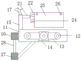
FIG. 1 is a top view of the structure of the present invention;
FIG. 2 is a side view of the cutting table structure of the present invention;
FIG. 3 is a side view of the second carriage and its associated components of the present invention;
FIG. 4 is a top view of the access panel and its component structures in accordance with the present invention;
fig. 5 is a side view of the rotary seat structure of the present invention.
In the figure: 1. a movable seat; 2. a first conveying base; 3. a first rotating shaft; 4. a delivery wheel; 5. a first conveyor belt; 6. a first motor; 7. a mounting frame; 8. a sliding seat; 9. a first chute; 10. a first slider; 11. a second conveying seat; 12. a second rotating shaft; 13. a second conveyor belt; 14. a second motor; 15. a support frame; 16. a connecting rod; 17. a chain; 18. a rotating seat; 19. a first hydraulic cylinder; 20. a side plate; 21. a second hydraulic cylinder; 22. taking a pallet; 23. a third chute; 24. a third slider; 25. a clamping plate; 26. a bidirectional hydraulic cylinder; 27. an auxiliary slide block; 28. an auxiliary lever; 29. a gear; 30. a rolling wheel; 31. a protection plate; 32. a movable rod; 33. pulling the block; 34. a spring; 35. and a baffle plate.
The specific implementation mode is as follows:
as shown in fig. 1 to 5, the following technical solutions are adopted in the present embodiment: a movable goods unloading frame for electric power materials comprises a moving seat 1, wherein one end of the moving seat 1 is fixedly connected with a first conveying seat 2, a plurality of conveying wheels 4 are arranged in the first conveying seat 2 at equal distances, two sides of the plurality of conveying wheels 4 are respectively movably connected to two sides in the first conveying seat 2 through first rotating shafts 3, one sides of the plurality of first rotating shafts 3 respectively penetrate through one side of the first conveying seat 2 and are connected through a first conveying belt 5 in a transmission manner, two sides of the other end of the first conveying seat 2 are fixedly connected with mounting frames 7, the lower ends of the two mounting frames 7 are respectively fixedly connected to two sides of the upper end of the moving seat 1, one opposite sides of the two mounting frames 7 are respectively and fixedly connected with sliding seats 8, one end in the two sliding seats 8 is respectively and fixedly connected with a first sliding chute 9, the two first sliding chutes 9 are respectively and slidably connected to one end of a second conveying seat 11 through first sliding blocks 10, seat 11 upper end both sides are fixedly connected with support frame 15 respectively, two are carried to the second the upper end of support frame 15 passes through connecting rod 16 fixed linking to each other, connecting rod 16's upper end fixedly connected with chain 17, the one end fixed connection that the other end of chain 17 extends to mounting bracket 7 is served at curb plate 20, the both sides of curb plate 20 are fixed connection respectively on one side of the upper end of two mounting brackets 7, connecting rod 16's the other end is served at getting goods board 22 through two second hydraulic cylinder 21 fixed connection.
Wherein, the other end of the goods taking plate 22 is fixedly connected with a third chute 23, two third sliding blocks 24 are slidably connected on two sides of the third chute 23, the other end of the two third sliding blocks 24 is fixedly connected with a clamping plate 25, the upper ends of the inner sides of the two clamping plates 25 are fixedly connected through a bidirectional hydraulic cylinder 26, the upper end of the side plate 20 is fixedly connected with a first hydraulic cylinder 19, the upper end of the first hydraulic cylinder 19 is fixedly connected with a rotating seat 18, the inside of the rotating seat 18 is rotatably connected with a gear 29 through a first rotating shaft 3, one end of a chain 17 is engaged and connected on the gear 29 in a transmission manner, one end of a first transmission belt 5 is connected with the output end of a first motor 6, the first motor 6 is correspondingly arranged on one side of the outer part of the first conveying seat 2, the inside of the second conveying seat 11 is movably connected with a plurality of conveying wheels 4 through a plurality of second rotating shafts, and a plurality of one side of second pivot 12 runs through one side to second transport seat 11 respectively and links to each other through the transmission of second conveyer belt 13, the one end of second conveyer belt 13 is fixed continuous through second motor 14 output, second motor 14 sets up on one side of the outside of second transport seat 11.
Wherein the third chute 23 is parallel to the two second hydraulic cylinders 21 and is disposed at one end of the goods taking plate 22, the lower end of the first slide block 10 is fixedly connected with an auxiliary slide block 27 through an auxiliary rod 28, one side of the auxiliary slide block 27 is disposed inside the first chute 9 of the second conveying seat, the other side of the auxiliary slide block 27 is fixedly connected to the two sides of the bottom end of the second conveying seat 11 through the auxiliary rod 28, the second conveying seat 11, the auxiliary slide block 27 and the auxiliary rod 28 are in a right-angled triangle structure, a groove is disposed at one end of the movable seat 1 corresponding to the second conveying seat 11, the second conveying seat 11 is nested in the groove and is nested with the movable seat 1, the two sides of the upper end of the first conveying seat 2 are fixedly connected with a protection plate 31, a movable rod 32 is disposed inside the protection plate 31, one end of the movable rod 32 penetrates to an external fixedly connected pull block 33 of the protection plate 31, just the outside nested connection of one end of movable rod 32 has spring 34, the both ends of spring 34 are fixed connection respectively on the outside of guard plate 31 and one side of drawing piece 33, the other end of movable rod 32 runs through to the inside fixedly connected with baffle 35 of guard plate 31, two baffle 35 corresponds the setting respectively in the both sides upper end of a plurality of first pivots 3.
Wherein, the lower end of the movable seat 1 is fixedly connected with a rolling wheel 30.
Wherein, the outside of conveying wheel 4 all wraps up the rubber pad.
Wherein the rotation direction of the first motor 6 is the same as the rotation direction of the second motor 14.
Wherein, the width of the first conveying seat 2 is the same as that of the second conveying seat 11.
The clamping plates 25 are correspondingly arranged right above the second conveying seat 11, and the width of the two clamping plates 25 is smaller than that of the second conveying seat 11 when the two clamping plates are unfolded by the bidirectional hydraulic cylinder 26.
Specifically, the method comprises the following steps: an electric power material movable unloading frame, when in use, a person can move the device through a rolling wheel 30, the goods on different goods can be conveniently stored and taken, when the person needs to take the goods on the high position on the goods frame, a first hydraulic cylinder 19 can be started, the first hydraulic cylinder 19 extends, so that the person can rotate on a chain 17 through a gear 29 on a rotating seat 18, so that the chain 17 drives a connecting rod 16 to rise, the connecting rod 16 rises, so as to drive a second conveying seat 11 to rise at one end of a moving seat 1, so as to enable the second conveying seat 11 to rise to be level with goods on the goods frame, then a second hydraulic cylinder 21 is started, so as to drive a goods taking plate 22 to approach towards the goods direction, so as to enable two clamping plates 25 arranged at one end of the goods taking plate 22 to be inserted on two sides of the goods, then a bidirectional hydraulic cylinder 26 is contracted, so as to drive the two clamping plates 25 to clamp the goods tightly, then the second hydraulic cylinder 21 is contracted, so, then 19 shrink of first pneumatic cylinder, accomodate second transport seat 11 and remove 1 upper groove to make first transport seat 2 and 11 parallel and level of second transport seat, then first motor 6 and second motor 14 start, thereby drive corresponding delivery wheel 4 in proper order and rotate, carry the goods, thereby accomplish the goods and take out from goods shelves, operate according to above-mentioned step is opposite, accomplish depositing of goods, simple and practical convenient.
While there have been shown and described what are at present considered to be the fundamental principles of the invention and its essential features and advantages, it will be understood by those skilled in the art that the invention is not limited by the embodiments described above, which are merely illustrative of the principles of the invention, but that various changes and modifications may be made therein without departing from the spirit and scope of the invention as defined by the appended claims and their equivalents.
Claims (1)
1. The movable goods unloading frame for the electric power materials comprises a moving seat (1) and is characterized in that one end of the moving seat (1) is fixedly connected with a first conveying seat (2), a plurality of conveying wheels (4) are arranged in the first conveying seat (2) at equal distances, two sides of the plurality of conveying wheels (4) are movably connected to two sides of the inner portion of the first conveying seat (2) through first rotating shafts (3), one sides of the plurality of first rotating shafts (3) penetrate through one sides of the first conveying seat (2) respectively and are connected through a first conveying belt (5) in a transmission mode, mounting frames (7) are fixedly connected to two sides of the other end of the first conveying seat (2), the lower ends of the two mounting frames (7) are fixedly connected to two sides of the upper end of the moving seat (1) respectively, and sliding seats (8) are fixedly connected to one sides of the two mounting frames (7) opposite to each other, one end of the inner part of each sliding seat (8) is fixedly connected with a first sliding chute (9), the inner parts of the two first sliding chutes (9) are respectively connected to one end of a second conveying seat (11) in a sliding way through first sliding blocks (10), two sides of the upper end of the second conveying seat (11) are respectively and fixedly connected with a supporting frame (15), the upper ends of the two supporting frames (15) are fixedly connected through a connecting rod (16), the upper end of the connecting rod (16) is fixedly connected with a chain (17), one end of the other end of the chain (17) extending to the mounting rack (7) is fixedly connected with one end of the side plate (20), the two sides of the side plate (20) are respectively and fixedly connected with one side of the upper ends of the two mounting racks (7), the other end of the connecting rod (16) is fixedly connected to one end of the goods taking plate (22) through two second hydraulic cylinders (21);
the other end of the goods taking plate (22) is fixedly connected with a third sliding chute (23), two third sliding blocks (24) are connected to two sides of the third sliding chute (23) in a sliding mode, a clamping plate (25) is fixedly connected to the other end of the two third sliding blocks (24), the upper ends of the inner sides of the two clamping plates (25) are fixedly connected through a two-way hydraulic cylinder (26), the upper end of the side plate (20) is fixedly connected with a first hydraulic cylinder (19), the upper end of the first hydraulic cylinder (19) is fixedly connected with a rotating seat (18), the inside of the rotating seat (18) is rotatably connected with a gear (29) through a first rotating shaft (3), one end of a chain (17) is connected to the gear (29) in a meshing transmission mode, one end of a first conveying belt (5) is connected with the output end of a first motor (6), and the first motor (6) is correspondingly arranged on one side of the outer portion of the first conveying seat (2, a plurality of conveying wheels (4) are movably connected inside the second conveying seat (11) through a plurality of second rotating shafts (12), one sides of the second rotating shafts (12) penetrate through one sides of the second conveying seat (11) respectively and are connected through a second conveying belt (13) in a transmission mode, one ends of the second conveying belts (13) are fixedly connected through output ends of second motors (14), and the second motors (14) are arranged on one side of the outer portion of the second conveying seat (11);
the third sliding chute (23) is correspondingly arranged on one end of the goods taking plate (22) in parallel with the two second hydraulic cylinders (21), the lower end of the first sliding block (10) is fixedly connected with an auxiliary sliding block (27) through an auxiliary rod (28), one side of the auxiliary sliding block (27) is arranged in the second conveying seat in the first sliding chute (9), the other side of the auxiliary sliding block (27) is fixedly connected to the two sides of the bottom end of the second conveying seat (11) through the auxiliary rod (28), the second conveying seat (11), the auxiliary sliding block (27) and the auxiliary rod (28) form a right-angled triangle structure, a groove is formed in one end of the inner part of the movable seat (1) corresponding to the position of the second conveying seat (11), the second conveying seat (11) is correspondingly nested in the groove and connected with the movable seat (1), and protection plates (31) are fixedly connected to the two sides of the upper end of the first conveying seat (2), a movable rod (32) penetrates through the protection plate (31), one end of the movable rod (32) penetrates through the outer fixed connection of the protection plate (31) and is connected with a pulling block (33), a spring (34) is connected with one end of the movable rod (32) in an embedded mode, two ends of the spring (34) are fixedly connected to the outer side of the protection plate (31) and one side of the pulling block (33) respectively, the other end of the movable rod (32) penetrates through the inner fixed connection of the protection plate (31) and is connected with baffle plates (35), and the two baffle plates (35) are correspondingly arranged at the upper ends of two sides of the first rotating shafts (3) respectively;
the lower end of the movable seat (1) is fixedly connected with a rolling wheel (30);
rubber pads are wrapped outside the conveying wheels (4);
the rotating direction of the first motor (6) is the same as that of the second motor (14);
the width of the first conveying seat (2) is the same as that of the second conveying seat (11);
the two clamping plates (25) are correspondingly arranged right above the second conveying seat (11), and the width of the two clamping plates (25) is smaller than that of the second conveying seat (11) when the two clamping plates (25) are unfolded through the bidirectional hydraulic cylinder (26).
Priority Applications (1)
| Application Number | Priority Date | Filing Date | Title |
|---|---|---|---|
| CN201810791777.2A CN108974740B (en) | 2018-07-18 | 2018-07-18 | Movable unloading rack for electric power materials |
Applications Claiming Priority (1)
| Application Number | Priority Date | Filing Date | Title |
|---|---|---|---|
| CN201810791777.2A CN108974740B (en) | 2018-07-18 | 2018-07-18 | Movable unloading rack for electric power materials |
Publications (2)
| Publication Number | Publication Date |
|---|---|
| CN108974740A CN108974740A (en) | 2018-12-11 |
| CN108974740B true CN108974740B (en) | 2020-10-27 |
Family
ID=64549768
Family Applications (1)
| Application Number | Title | Priority Date | Filing Date |
|---|---|---|---|
| CN201810791777.2A Expired - Fee Related CN108974740B (en) | 2018-07-18 | 2018-07-18 | Movable unloading rack for electric power materials |
Country Status (1)
| Country | Link |
|---|---|
| CN (1) | CN108974740B (en) |
Families Citing this family (6)
| Publication number | Priority date | Publication date | Assignee | Title |
|---|---|---|---|---|
| CN109896311B (en) * | 2019-03-19 | 2021-01-15 | 浙江英特沃斯科技有限公司 | Heat conduction polymer combined material is with conveyer that has stable structure |
| CN112173521B (en) * | 2020-09-25 | 2021-12-10 | 中通服供应链管理有限公司 | Warehouse logistics conveying device |
| CN112255477B (en) * | 2020-09-29 | 2022-07-22 | 国网山东省电力公司烟台供电公司 | Intelligent power equipment quality detection equipment |
| CN113895975B (en) * | 2021-09-24 | 2022-12-06 | 南通职业大学 | Mechanical automatic unloading device with protection function |
| CN113859903B (en) * | 2021-11-06 | 2023-03-21 | 安徽华燕物流有限公司 | Automatic loading system |
| CN114873526B (en) * | 2022-07-12 | 2022-09-16 | 太原理工大学 | Automatic hanging unloading device and binocular recognition unloading method thereof |
Citations (5)
| Publication number | Priority date | Publication date | Assignee | Title |
|---|---|---|---|---|
| US6467606B1 (en) * | 2000-08-14 | 2002-10-22 | Langen Packaging, Inc. | Conveyor system with diverter |
| CN107555190A (en) * | 2017-08-29 | 2018-01-09 | 国网山东省电力公司平原县供电公司 | Shelf are unloaded in a kind of Power Material activity |
| CN107673277A (en) * | 2017-09-29 | 2018-02-09 | 曹欣欣 | A kind of fork truck for unloading of being easy to get in stocks |
| CN207192361U (en) * | 2017-08-01 | 2018-04-06 | 贵州耀泰物流有限责任公司 | A kind of logistics automatic loading and unloading goods device |
| CN107892152A (en) * | 2017-11-08 | 2018-04-10 | 广东宏大增化民爆有限责任公司 | A kind of carrying method of packing explosive carton |
Family Cites Families (1)
| Publication number | Priority date | Publication date | Assignee | Title |
|---|---|---|---|---|
| US6902039B2 (en) * | 2002-05-06 | 2005-06-07 | Timothy R. Kunch | Protective shield apparatus for fork lift trucks |
-
2018
- 2018-07-18 CN CN201810791777.2A patent/CN108974740B/en not_active Expired - Fee Related
Patent Citations (5)
| Publication number | Priority date | Publication date | Assignee | Title |
|---|---|---|---|---|
| US6467606B1 (en) * | 2000-08-14 | 2002-10-22 | Langen Packaging, Inc. | Conveyor system with diverter |
| CN207192361U (en) * | 2017-08-01 | 2018-04-06 | 贵州耀泰物流有限责任公司 | A kind of logistics automatic loading and unloading goods device |
| CN107555190A (en) * | 2017-08-29 | 2018-01-09 | 国网山东省电力公司平原县供电公司 | Shelf are unloaded in a kind of Power Material activity |
| CN107673277A (en) * | 2017-09-29 | 2018-02-09 | 曹欣欣 | A kind of fork truck for unloading of being easy to get in stocks |
| CN107892152A (en) * | 2017-11-08 | 2018-04-10 | 广东宏大增化民爆有限责任公司 | A kind of carrying method of packing explosive carton |
Also Published As
| Publication number | Publication date |
|---|---|
| CN108974740A (en) | 2018-12-11 |
Similar Documents
| Publication | Publication Date | Title |
|---|---|---|
| CN108974740B (en) | Movable unloading rack for electric power materials | |
| CN208747166U (en) | One kind unloading cage machine | |
| CN210824146U (en) | Conveyor for cement manufacture | |
| CN212531447U (en) | Automatic change panel pile up neatly device | |
| CN112744391A (en) | Skin care products packing plant | |
| CN112758648A (en) | Aluminum profile storage device | |
| CN106429393B (en) | A kind of upper brick machine | |
| CN112478586B (en) | Automatic material transferring and conveying device and control method thereof | |
| CN112027550B (en) | A laborsaving type handling device for material transport uses | |
| CN114955510B (en) | Automatic boxing equipment | |
| CN216836155U (en) | Automatic mattress stacking machine | |
| CN108357863B (en) | Parallel lifting conveying transmission structure and transmission method thereof | |
| CN108328342B (en) | Full-automatic metal plate stacking equipment | |
| CN216334923U (en) | Transfer platform for AGV transferring goods | |
| CN112758460B (en) | Labeling process of high-efficiency automatic circuit board labeling system | |
| CN212374339U (en) | 180 tipping arrangement that conveyer was used | |
| CN211768250U (en) | Conveying mechanism | |
| CN209973762U (en) | Loading platform | |
| CN209889763U (en) | Framing device | |
| CN219839132U (en) | Automatic feeding and discharging equipment based on AGV | |
| CN213864274U (en) | Loading and unloading device for motor tray | |
| CN111697259A (en) | Battery overturning and edge covering device | |
| CN218144347U (en) | Unstacking device | |
| CN213474447U (en) | Anti-toppling type electric power transmission device | |
| CN217995881U (en) | Tray type heavy roller jacking transfer machine |
Legal Events
| Date | Code | Title | Description |
|---|---|---|---|
| PB01 | Publication | ||
| PB01 | Publication | ||
| SE01 | Entry into force of request for substantive examination | ||
| SE01 | Entry into force of request for substantive examination | ||
| GR01 | Patent grant | ||
| GR01 | Patent grant | ||
| CF01 | Termination of patent right due to non-payment of annual fee | ||
| CF01 | Termination of patent right due to non-payment of annual fee |
Granted publication date: 20201027 Termination date: 20210718 |