CN108927417B - Hot extrusion forming die and forming method for special-shaped deep-cavity complex-structure support - Google Patents
Hot extrusion forming die and forming method for special-shaped deep-cavity complex-structure support Download PDFInfo
- Publication number
- CN108927417B CN108927417B CN201810507707.XA CN201810507707A CN108927417B CN 108927417 B CN108927417 B CN 108927417B CN 201810507707 A CN201810507707 A CN 201810507707A CN 108927417 B CN108927417 B CN 108927417B
- Authority
- CN
- China
- Prior art keywords
- die
- guide
- hot extrusion
- special
- female
- Prior art date
- Legal status (The legal status is an assumption and is not a legal conclusion. Google has not performed a legal analysis and makes no representation as to the accuracy of the status listed.)
- Active
Links
Images



Classifications
-
- B—PERFORMING OPERATIONS; TRANSPORTING
- B21—MECHANICAL METAL-WORKING WITHOUT ESSENTIALLY REMOVING MATERIAL; PUNCHING METAL
- B21C—MANUFACTURE OF METAL SHEETS, WIRE, RODS, TUBES OR PROFILES, OTHERWISE THAN BY ROLLING; AUXILIARY OPERATIONS USED IN CONNECTION WITH METAL-WORKING WITHOUT ESSENTIALLY REMOVING MATERIAL
- B21C25/00—Profiling tools for metal extruding
- B21C25/02—Dies
-
- B—PERFORMING OPERATIONS; TRANSPORTING
- B21—MECHANICAL METAL-WORKING WITHOUT ESSENTIALLY REMOVING MATERIAL; PUNCHING METAL
- B21C—MANUFACTURE OF METAL SHEETS, WIRE, RODS, TUBES OR PROFILES, OTHERWISE THAN BY ROLLING; AUXILIARY OPERATIONS USED IN CONNECTION WITH METAL-WORKING WITHOUT ESSENTIALLY REMOVING MATERIAL
- B21C23/00—Extruding metal; Impact extrusion
- B21C23/001—Extruding metal; Impact extrusion to improve the material properties, e.g. lateral extrusion
-
- B—PERFORMING OPERATIONS; TRANSPORTING
- B21—MECHANICAL METAL-WORKING WITHOUT ESSENTIALLY REMOVING MATERIAL; PUNCHING METAL
- B21C—MANUFACTURE OF METAL SHEETS, WIRE, RODS, TUBES OR PROFILES, OTHERWISE THAN BY ROLLING; AUXILIARY OPERATIONS USED IN CONNECTION WITH METAL-WORKING WITHOUT ESSENTIALLY REMOVING MATERIAL
- B21C25/00—Profiling tools for metal extruding
- B21C25/02—Dies
- B21C25/025—Selection of materials therefor
Landscapes
- Engineering & Computer Science (AREA)
- Mechanical Engineering (AREA)
- Forging (AREA)
- Extrusion Of Metal (AREA)
Abstract
The hot extrusion forming die comprises an upper die, a lower die, a guide pillar and a guide sleeve, wherein the lower surface of the upper die and the upper surface of the lower die are horizontal planes, a male die is arranged on the lower surface of the upper die, a female die corresponding to the male die is arranged on the upper surface of the lower die, the female die is integrally of a concave structure, a flash groove is arranged around the female die, a guide groove is respectively arranged around the flash groove, and a gap is formed between the male die and the female die after the male die and the female die are matched to form the shape of a support forging; guide post holes are correspondingly arranged at two diagonal positions of the upper die and the lower die, a guide sleeve is arranged in each guide post hole, the guide sleeves and the guide post holes are fastened in a press fit mode, and the guide posts are respectively inserted into the guide sleeves corresponding to the upper die and the lower die to position the upper die and the lower die; according to the invention, through the design of the male die, the female die, the flash groove and the diversion groove, the flow of the blank is controlled so as to control the dimensional precision of the bracket forging, and redundant blanks can be discharged.
Description
Technical Field
The invention relates to the technical field of machining equipment, in particular to a hot extrusion forming die for a special-shaped deep-cavity complex-structure support.
Background
The major trend of national defense safety requires that the response speed of the updated weapon equipment is faster and faster, the technical and tactical indexes are higher and higher, the weapon equipment gradually shows the characteristics of light weight, complexity and integration of the structure, the requirement on the quality-strength ratio of the components is continuously improved, and the contradiction between the light weight of the structure and the high strength requirement is more and more prominent. In order to meet the requirements, the aerospace weapon components adopt a large number of light alloy special-shaped complex thin-wall structures. The cross section of the support for the certain type of the spaceflight weapon is rectangular and is of a deep cavity structure, the bottom surface is a hollow arc-shaped surface, the peripheral side walls are vertical ribs, one side wall is provided with two ears, the sectional area of a part is large, the material distribution is uneven, and the support is not a traditional axisymmetric part.
At present, the special-shaped deep-cavity complex-structure support is manufactured by casting machine. The method has serious disadvantages, such as the material utilization rate is often lower than 30 percent, and the material consumption is serious; the casting is deformed in the processes of machining and heat treatment, the scrapping risk is high, and the manufacturing cost is high. The hot extrusion near-net forming technology can well solve the problems, so that the material utilization rate is greatly improved, the deformation of parts is easy to control, the required machining time is greatly shortened, meanwhile, the deformation resistance of the material can be reduced in the hot extrusion process, the plasticity of the material is improved, the material performance can be further improved, a hot extrusion product with good mechanical property is obtained, and the product performance can be ensured to meet the index requirements. In addition, the hot extrusion forming die can be repeatedly used, the service life is long, and the production cost is greatly reduced.
Disclosure of Invention
The technical problem solved by the invention is as follows: the defects of the prior art are overcome, and the hot extrusion forming die which is simple in structure, capable of effectively improving the hot extrusion forming precision of the special-shaped deep-cavity complex-structure support and high in use stability is provided.
The technical solution of the invention is as follows: the hot extrusion forming die for the special-shaped deep-cavity complex-structure support forge piece comprises an upper die, a lower die, a guide pillar and a guide sleeve, wherein the lower surface of the upper die and the upper surface of the lower die are horizontal planes, a male die is arranged on the lower surface of the upper die, a female die corresponding to the male die is arranged on the upper surface of the lower die, the female die is integrally of an inwards concave structure, a flash groove is arranged around the female die, a guide groove is respectively arranged around each flash groove, and a gap is formed between the male die and the female die after the male die and the; guide post holes are correspondingly arranged at two diagonal positions of the upper die and the lower die respectively, a guide sleeve is arranged in each guide post hole, the guide sleeves and the guide post holes are fastened in a press fit mode, the guide posts are respectively inserted into the guide sleeves corresponding to the upper die and the lower die, the upper die and the lower die are positioned, and a gap of 0.15 mm-0.5 mm is reserved between each guide post and each guide sleeve; the upper die and the lower die are respectively provided with 9 heating tube holes and 3 thermocouple holes.
The radius of the cambered surfaces of the convex surface of the convex die and the concave surface of the concave die is preferably 467mm, the integral draft angle of the convex die and the concave die is 1-10 degrees, and the radius of the fillet is 3-6 mm.
Preferably, the upper die and the lower die are made of heat-resistant steel, hard alloy or steel-bonded hard alloy, and the guide pillar and the guide sleeve are made of bearing steel, hot-work die steel or carbon tool steel.
Preferably, the upper die, the lower die, the guide pillar and the guide sleeve all need heat treatment so as to improve the strength, the hardness and the wear resistance and prolong the service life of the die.
Preferably, the surfaces of the male die, the female die, the guide post hole, the flash groove, the guide post and the guide sleeve need to be polished and polished to reduce the surface roughness, so as to facilitate demoulding and improve the surface quality of the forged piece, the surface roughness Ra of the male die, the female die, the flash groove and the guide groove is less than or equal to 0.8, the Ra of the guide post is less than or equal to 0.4, the Ra of the guide sleeve is less than or equal to 0.8, and the Ra of the guide post hole is less than.
The invention discloses a hot extrusion forming method of a special-shaped deep-cavity complex-structure bracket forge piece, which uses a hot extrusion forming die of the special-shaped deep-cavity complex-structure bracket forge piece in any one of technical schemes 1-5, and the forming method comprises the following steps: step one, placing a light alloy blank into a female die of a lower die, step two, performing hot extrusion by using a male die of an upper die, extruding the blank in the extrusion process, filling a cavity formed after the male die is matched with the female die, extending the redundant blank outwards from a flash groove, and realizing the hot extrusion accurate forming of the bracket.
Compared with the prior art, the invention has the advantages that:
according to the invention, through the design of the male die, the female die, the flash groove and the diversion groove, the flow of the blank can be controlled, so that the dimensional precision of the support forging is ensured, the redundant blank can be discharged, the service performance, the stability and the service life of the die can be improved, the obtained forging has the advantages of fine and compact internal crystal grains, reasonable metal flow line and good surface quality, the mechanical performance of the forging is improved by more than 30%, the existing hot extrusion equipment is not required to be modified, the structure is simple, and the cost is lower.
Drawings
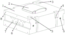
Figure 1 is a top view of the upper die,
figure 2 is a perspective view of the upper die,
figure 3 is a top view of the lower die,
figure 4 is a perspective view of the lower die,
figure 5 is a schematic view of the guide post,
fig. 6 is a schematic view of the guide sleeve.
Detailed Description
Example 1:
as shown in fig. 1 to 6, the hot extrusion forming die for the special-shaped deep-cavity complex-structure support forge piece described in this embodiment includes an upper die 1, a lower die 9, a guide pillar 13, and a guide sleeve 14, where the lower surface of the upper die 1 and the upper surface of the lower die 9 are horizontal planes, the lower surface of the upper die 1 is provided with a male die 2, the upper surface of the lower die 9 is provided with a female die 10 corresponding to the male die 2, the female die 10 is integrally of a concave structure, a flash groove 11 is arranged around the female die 10, one guide groove 12 is respectively arranged around the flash groove 11, and a gap exists between the male die 2 and the female die 10 after the male die and the female die are matched; adopting double guide columns, respectively arranging guide column holes 3 at two diagonal positions of an upper die 1 and a lower die 9, placing guide sleeves 14 in the guide column holes 3, adopting press fit fastening between the guide sleeves and the guide columns, placing guide columns 13 in the guide sleeves 14, and leaving a gap of 0.15mm between the guide columns and the guide sleeves; the upper die 1 and the lower die 9 are respectively provided with 9 heating pipe holes 7 and 3 thermocouple holes 6. The radius of the cambered surfaces of the convex surface of the convex die 2 and the concave surface of the concave die 10 is 467mm, the integral draft angle of the convex die 2 and the concave die 10 is 1 degree, and the radius of the fillet is 5 mm. The upper die 1 and the lower die 9 are made of low heat-resistant high-toughness steel 5CrMnMo, and the guide pillar 13 and the guide sleeve 14 are made of bearing steel SUJ 12; the upper die 1, the lower die 9, the guide post 13 and the guide sleeve 14 have enough strength, hardness and wear resistance after heat treatment; the surfaces of the male die 2, the female die 10, the flash groove 11, the guide pillar 13 and the guide sleeve 14 are subjected to grinding and polishing treatment, and the surface roughness of the male die, the female die, the flash groove and the guide groove Ra0.8, the surface roughness of the guide pillar Ra0.4, the surface roughness of the guide sleeve Ra0.8 and the surface roughness of the guide pillar hole Ra1.6 are obtained.
In the use, put into the die 10 of lower mould 9 with 5A06 aluminum alloy blank, utilize the terrace die 2 of last mould 1 to carry out the hot extrusion, the blank is extruded in the extrusion process, the die cavity after die 10 and terrace die 2 cooperation is filled up simultaneously, and unnecessary blank is then outwards extended from overlap groove 11, finally realize the hot extrusion and take shape accurately, and can avoid the blank to the damage that the extrusion of terrace die 2 and die 10 edge caused, can effectively improve the life of mould, stability obtains promoting. In the hot extrusion forming process, the air in the closed cavity after the male die 2 is matched with the female die 10 can be discharged through the design of the diversion trenches 12, and the hot extrusion surface performance of the support forge piece is improved. And after the hot extrusion is finished, the upper die 1 moves upwards to open the die, the forge piece is taken out, and the support hot extrusion process is finished. And transferring the support forge piece subjected to hot extrusion forming to subsequent processes, and finally processing the support forge piece into a support finished product through the processes of heat treatment, mechanical processing and the like.
Example 2:
as shown in fig. 1 to 6, the hot extrusion forming die for the special-shaped deep-cavity complex-structure support forge piece described in this embodiment includes an upper die 1, a lower die 9, a guide pillar 13, and a guide sleeve 14, where the lower surface of the upper die 1 and the upper surface of the lower die 9 are horizontal planes, the lower surface of the upper die 1 is provided with a male die 2, the upper surface of the lower die 9 is provided with a female die 10 corresponding to the male die 2, the female die 10 is integrally of a concave structure, a flash groove 11 is arranged around the female die 10, one guide groove 12 is respectively arranged around the flash groove 11, and a gap exists between the male die 2 and the female die 10 after the male die and the female die are matched; adopting double guide columns, respectively arranging guide column holes 3 at two diagonal positions of an upper die 1 and a lower die 9, placing guide sleeves 14 in the guide column holes 3, adopting press fit fastening between the guide sleeves and the guide columns, placing guide columns 13 in the guide sleeves 14, and leaving a gap of 0.3mm between the guide columns and the guide sleeves; the upper die 1 and the lower die 9 are respectively provided with 9 heating pipe holes 7 and 3 thermocouple holes 6. The radius of the cambered surfaces of the convex surface of the convex die 2 and the concave surface of the concave die 10 is 467mm, the integral draft angle of the convex die 2 and the concave die 10 is 10 degrees, and the radius of the fillet is 6 mm. The upper die 1 and the lower die 9 are made of medium heat-resistant toughness steel 4Cr5MoSiV, and the guide pillar 13 and the guide sleeve 14 are made of carbon tool steel T7; the upper die 1, the lower die 9, the guide post 13 and the guide sleeve 14 have enough strength, hardness and wear resistance after heat treatment; the surfaces of the male die 2, the female die 10, the flash groove 11, the guide pillar 13 and the guide sleeve 14 are subjected to grinding and polishing treatment, and the surface roughness of the male die, the female die, the flash groove and the guide groove Ra0.4, the surface roughness of the guide pillar Ra0.8 and the surface roughness of the guide sleeve Ra1.6 are equal to the surface roughness of the guide pillar.
In the use process, the VW63Z high-temperature-resistant magnesium alloy blank is placed into the female die 10 of the lower die 9, the male die 2 of the upper die 1 is used for hot extrusion, the blank is extruded in the extrusion process, the female die 10 and the cavity formed by matching the male die 2 are filled, redundant blank extends outwards from the flash groove 11, finally, the hot extrusion precise forming is realized, the damage to the edges of the male die 2 and the female die 10 caused by the extrusion of the blank can be avoided, the service life of the die can be effectively prolonged, and the stability is improved. In the hot extrusion forming process, the air in the closed cavity after the male die 2 is matched with the female die 10 can be discharged through the design of the diversion trenches 12, and the hot extrusion surface performance of the support forge piece is improved. After the hot extrusion is completed, the upper die 1 moves upwards to open the die, the support forge piece is clamped inside the female die 10, the forge piece is pried out by a crowbar through the diversion trench 12, and the workpiece is simple and convenient to take down and high in efficiency. And transferring the support forge piece subjected to hot extrusion forming to subsequent processes, and finally processing the support forge piece into a support finished product through the processes of heat treatment, mechanical processing and the like.
Through multiple researches and verifications of the inventor, the gap between the guide pillar and the guide sleeve can be selected from 0.15 mm-0.5 mm, the integral draft angle is selected from 1-10 degrees, and the fillet radius is selected from 3 mm-6 mm, so that the demolding is facilitated.
The above description is an embodiment of the present invention. The present invention is not limited to the above embodiments, and any structural changes made under the teaching of the present invention shall fall within the protection scope of the present invention, which is similar or similar to the technical solutions of the present invention.
Those skilled in the art will appreciate that those matters not described in detail in the present specification are well known in the art.
Claims (10)
1. The hot extrusion forming die for the special-shaped deep-cavity complex-structure support forge piece is characterized in that: the die comprises an upper die, a lower die, a guide pillar and a guide sleeve, wherein the lower surface of the upper die and the upper surface of the lower die are horizontal planes, a male die is arranged on the lower surface of the upper die, a female die corresponding to the male die is arranged on the upper surface of the lower die, the female die is integrally of an inwards concave structure, flash grooves are arranged around the female die, guide grooves are respectively arranged around the flash grooves, and a gap is formed between the male die and the female die after the male die and the female die are matched to form the shape; guide post holes are correspondingly arranged at two diagonal positions of the upper die and the lower die respectively, a guide sleeve is arranged in each guide post hole, the guide sleeves and the guide post holes are fastened in a press fit mode, and the guide posts are inserted into the corresponding guide sleeves of the upper die and the lower die respectively to position the upper die and the lower die; a gap is reserved between the guide pillar and the guide sleeve; heating pipe holes and thermocouple holes are respectively arranged in the upper die and the lower die.
2. The hot extrusion forming die for the special-shaped deep-cavity complex-structure bracket forge piece according to claim 1, characterized in that: the gap between the guide pillar and the guide sleeve is 0.15-0.5 mm.
3. The hot extrusion forming die for the special-shaped deep-cavity complex-structure bracket forge piece according to claim 1, characterized in that: nine heating tube holes are arranged.
4. The hot extrusion forming die for the special-shaped deep-cavity complex-structure bracket forge piece according to claim 1, characterized in that: the number of the thermocouple holes is three.
5. The hot extrusion forming die for the special-shaped deep-cavity complex-structure bracket forge piece according to claim 1, characterized in that: the radius of the cambered surfaces of the convex surface of the convex die and the concave surface of the concave die is 467mm, the integral draft angle of the convex die and the concave die is 1-10 degrees, and the radius of the fillet is 3-6 mm.
6. The hot extrusion forming die for the special-shaped deep-cavity complex-structure bracket forge piece according to claim 1, characterized in that: the upper die and the lower die are made of heat-resistant steel, hard alloy or steel-bonded hard alloy, and the guide pillar and the guide sleeve are made of bearing steel, hot-work die steel or carbon tool steel.
7. The hot extrusion forming die for the special-shaped deep-cavity complex-structure bracket forge piece according to claim 1, characterized in that: and carrying out heat treatment on the upper die, the lower die, the guide pillar and the guide sleeve.
8. The hot extrusion forming die for the special-shaped deep-cavity complex-structure bracket forge piece according to claim 1, characterized in that: and (4) grinding and polishing the surfaces of the male die, the female die, the guide post hole, the flash groove, the guide post and the guide sleeve.
9. The hot extrusion forming die for the special-shaped deep-cavity complex-structure bracket forge piece according to claim 8, characterized in that: the surface roughness Ra of the male die, the female die, the flash groove and the guide groove is less than or equal to 0.8, the Ra of the guide pillar is less than or equal to 0.4, the Ra of the guide sleeve is less than or equal to 0.8, and the Ra of the guide pillar hole is less than or equal to 1.6.
10. The hot extrusion forming method of the special-shaped deep-cavity complex-structure support forge piece is characterized in that the hot extrusion forming die of the special-shaped deep-cavity complex-structure support forge piece is used as in any one of claims 1-9: the method comprises the following steps:
step one, placing a light alloy blank into a female die of a lower die;
step two, hot extrusion is carried out by using a male die of an upper die, a blank is extruded in the extrusion process, a cavity formed after the male die is matched with the female die is filled, and redundant blank extends outwards from the flash groove, so that the hot extrusion accurate forming of the support is realized;
and step three, after the hot extrusion is finished, the upper die moves upwards to open the die, the forge piece is taken out, and the support hot extrusion process is finished.
Priority Applications (1)
| Application Number | Priority Date | Filing Date | Title |
|---|---|---|---|
| CN201810507707.XA CN108927417B (en) | 2018-05-24 | 2018-05-24 | Hot extrusion forming die and forming method for special-shaped deep-cavity complex-structure support |
Applications Claiming Priority (1)
| Application Number | Priority Date | Filing Date | Title |
|---|---|---|---|
| CN201810507707.XA CN108927417B (en) | 2018-05-24 | 2018-05-24 | Hot extrusion forming die and forming method for special-shaped deep-cavity complex-structure support |
Publications (2)
| Publication Number | Publication Date |
|---|---|
| CN108927417A CN108927417A (en) | 2018-12-04 |
| CN108927417B true CN108927417B (en) | 2020-06-19 |
Family
ID=64449483
Family Applications (1)
| Application Number | Title | Priority Date | Filing Date |
|---|---|---|---|
| CN201810507707.XA Active CN108927417B (en) | 2018-05-24 | 2018-05-24 | Hot extrusion forming die and forming method for special-shaped deep-cavity complex-structure support |
Country Status (1)
| Country | Link |
|---|---|
| CN (1) | CN108927417B (en) |
Families Citing this family (3)
| Publication number | Priority date | Publication date | Assignee | Title |
|---|---|---|---|---|
| CN110394401A (en) * | 2019-08-29 | 2019-11-01 | 洛阳Lyc轴承有限公司 | A kind of shaping methods and shaping mould of high-carbon chromium steel thin-wall bearing ferrule |
| CN112371891B (en) * | 2020-10-19 | 2023-02-07 | 哈尔滨工业大学 | Semi-solid thixoforging device for 2A14 aluminum alloy thin-wall high-rib deep-cavity shell part and application method |
| CN114472575B (en) * | 2021-12-22 | 2024-04-05 | 北京航星机器制造有限公司 | Multidirectional hot extrusion forming die and forming method for light saddle-shaped end frame structure |
Family Cites Families (5)
| Publication number | Priority date | Publication date | Assignee | Title |
|---|---|---|---|---|
| CN202239415U (en) * | 2011-10-14 | 2012-05-30 | 天津市天锻压力机有限公司 | Heat preservation structure of isothermal forging hydraulic press for magnesium alloy wheel hub |
| CN103447443B (en) * | 2013-08-30 | 2015-06-10 | 衡水裕菖铸锻有限公司 | Single-tooth track plate semi-open and semi-closed blanking mold and single-tooth track plate forging method |
| KR20150042495A (en) * | 2013-10-11 | 2015-04-21 | 주식회사 이노윌 | Press Metal Die for Heat Exchanging Plate, Method and Plate thereof |
| CN106938312A (en) * | 2017-01-19 | 2017-07-11 | 安徽铖友汽车零部件制造有限公司 | Auto parts and components forging mold component |
| CN107081400B (en) * | 2017-06-29 | 2018-09-25 | 中北大学 | A kind of mold for hollow blank backward extrusion hollow object |
-
2018
- 2018-05-24 CN CN201810507707.XA patent/CN108927417B/en active Active
Also Published As
| Publication number | Publication date |
|---|---|
| CN108927417A (en) | 2018-12-04 |
Similar Documents
| Publication | Publication Date | Title |
|---|---|---|
| CN108927417B (en) | Hot extrusion forming die and forming method for special-shaped deep-cavity complex-structure support | |
| CN101332476B (en) | Precise extrusion molding method of thin wall long-pipe shaped parts bland and special mould | |
| CN108526238B (en) | Hot extrusion near-net forming method for asymmetric aluminum alloy flange plate with lugs | |
| CN202752523U (en) | Automobile steering knuckle multidirectional die forging precision forging forming die | |
| CN102641955B (en) | Mould capable of forming three-way pipe on one-way pressure machine and forming method thereof | |
| CN102335810B (en) | Method for forming precise slender internal spline tube | |
| CN102672096A (en) | Precision die forging and shaping technical method for automobile steering knuckle rough type parts | |
| CN105436350A (en) | Forming method for banjo axle housing | |
| CN104624906B (en) | A kind of forging mold and forging method | |
| CN105328020A (en) | Stamping tool for front ring in flame tube and working method of stamping tool | |
| CN109894562A (en) | A kind of barrel-shaped thin-wall part demoulding integrated mould of the high muscle of inner wall grid and manufacturing process | |
| CN103480681A (en) | Mold structure for semi-hollow profile with high slenderness ratio and manufacturing method of mold structure | |
| CN106825378B (en) | A kind of H-type thin-walled diskware low load continuous and local incremental forming device and method | |
| CN109622648B (en) | Asymmetric continuous large-deformation extrusion forming method for magnesium alloy | |
| CN104384427A (en) | Method for forming precision forge piece of wind power generation spindle | |
| CN102500633A (en) | Method for forming cup-shaped component with gear | |
| CN104826972B (en) | The continuous upsetting die of I shape joint and forming technology thereof | |
| CN103599955B (en) | It is a kind of for alloy state for 6061FT6 Large Flat width thin-wall section mould structure | |
| CN203917595U (en) | A kind of near net forming mould of magnesium alloy honeycomb blind hole structural member | |
| CN104942200A (en) | I-shaped joint rotating die and forming process thereof | |
| CN106041415B (en) | A kind of hollow valve filled with sodium manufacturing process squeezing base | |
| CN205056912U (en) | Improvement structure of perpendicular two -way double action forging module | |
| CN105964846A (en) | Hollow convex tooth type forging and molding method thereof | |
| CN103521545B (en) | Final extrusion forming die for high-strength complicated aluminum alloy special-shape outer hexagonal base metal plate | |
| CN113617994A (en) | Hot extrusion forming process and die for long-neck shaft tube |
Legal Events
| Date | Code | Title | Description |
|---|---|---|---|
| PB01 | Publication | ||
| PB01 | Publication | ||
| SE01 | Entry into force of request for substantive examination | ||
| SE01 | Entry into force of request for substantive examination | ||
| GR01 | Patent grant | ||
| GR01 | Patent grant |