CN108475145B - Image recognition device, image recognition method, and image recognition unit - Google Patents
Image recognition device, image recognition method, and image recognition unit Download PDFInfo
- Publication number
- CN108475145B CN108475145B CN201680078749.5A CN201680078749A CN108475145B CN 108475145 B CN108475145 B CN 108475145B CN 201680078749 A CN201680078749 A CN 201680078749A CN 108475145 B CN108475145 B CN 108475145B
- Authority
- CN
- China
- Prior art keywords
- image
- pattern
- image recognition
- line
- image display
- Prior art date
- Legal status (The legal status is an assumption and is not a legal conclusion. Google has not performed a legal analysis and makes no representation as to the accuracy of the status listed.)
- Active
Links
Images


Classifications
-
- G—PHYSICS
- G06—COMPUTING; CALCULATING OR COUNTING
- G06F—ELECTRIC DIGITAL DATA PROCESSING
- G06F3/00—Input arrangements for transferring data to be processed into a form capable of being handled by the computer; Output arrangements for transferring data from processing unit to output unit, e.g. interface arrangements
- G06F3/01—Input arrangements or combined input and output arrangements for interaction between user and computer
- G06F3/03—Arrangements for converting the position or the displacement of a member into a coded form
- G06F3/041—Digitisers, e.g. for touch screens or touch pads, characterised by the transducing means
- G06F3/042—Digitisers, e.g. for touch screens or touch pads, characterised by the transducing means by opto-electronic means
- G06F3/0425—Digitisers, e.g. for touch screens or touch pads, characterised by the transducing means by opto-electronic means using a single imaging device like a video camera for tracking the absolute position of a single or a plurality of objects with respect to an imaged reference surface, e.g. video camera imaging a display or a projection screen, a table or a wall surface, on which a computer generated image is displayed or projected
-
- G—PHYSICS
- G01—MEASURING; TESTING
- G01B—MEASURING LENGTH, THICKNESS OR SIMILAR LINEAR DIMENSIONS; MEASURING ANGLES; MEASURING AREAS; MEASURING IRREGULARITIES OF SURFACES OR CONTOURS
- G01B11/00—Measuring arrangements characterised by the use of optical techniques
- G01B11/24—Measuring arrangements characterised by the use of optical techniques for measuring contours or curvatures
- G01B11/25—Measuring arrangements characterised by the use of optical techniques for measuring contours or curvatures by projecting a pattern, e.g. one or more lines, moiré fringes on the object
-
- G—PHYSICS
- G01—MEASURING; TESTING
- G01B—MEASURING LENGTH, THICKNESS OR SIMILAR LINEAR DIMENSIONS; MEASURING ANGLES; MEASURING AREAS; MEASURING IRREGULARITIES OF SURFACES OR CONTOURS
- G01B11/00—Measuring arrangements characterised by the use of optical techniques
- G01B11/002—Measuring arrangements characterised by the use of optical techniques for measuring two or more coordinates
-
- G—PHYSICS
- G06—COMPUTING; CALCULATING OR COUNTING
- G06F—ELECTRIC DIGITAL DATA PROCESSING
- G06F3/00—Input arrangements for transferring data to be processed into a form capable of being handled by the computer; Output arrangements for transferring data from processing unit to output unit, e.g. interface arrangements
- G06F3/01—Input arrangements or combined input and output arrangements for interaction between user and computer
- G06F3/03—Arrangements for converting the position or the displacement of a member into a coded form
- G06F3/0304—Detection arrangements using opto-electronic means
- G06F3/0317—Detection arrangements using opto-electronic means in co-operation with a patterned surface, e.g. absolute position or relative movement detection for an optical mouse or pen positioned with respect to a coded surface
-
- G—PHYSICS
- G06—COMPUTING; CALCULATING OR COUNTING
- G06F—ELECTRIC DIGITAL DATA PROCESSING
- G06F3/00—Input arrangements for transferring data to be processed into a form capable of being handled by the computer; Output arrangements for transferring data from processing unit to output unit, e.g. interface arrangements
- G06F3/01—Input arrangements or combined input and output arrangements for interaction between user and computer
- G06F3/03—Arrangements for converting the position or the displacement of a member into a coded form
- G06F3/041—Digitisers, e.g. for touch screens or touch pads, characterised by the transducing means
- G06F3/042—Digitisers, e.g. for touch screens or touch pads, characterised by the transducing means by opto-electronic means
- G06F3/0421—Digitisers, e.g. for touch screens or touch pads, characterised by the transducing means by opto-electronic means by interrupting or reflecting a light beam, e.g. optical touch-screen
-
- G—PHYSICS
- G06—COMPUTING; CALCULATING OR COUNTING
- G06T—IMAGE DATA PROCESSING OR GENERATION, IN GENERAL
- G06T7/00—Image analysis
- G06T7/50—Depth or shape recovery
- G06T7/521—Depth or shape recovery from laser ranging, e.g. using interferometry; from the projection of structured light
-
- G—PHYSICS
- G06—COMPUTING; CALCULATING OR COUNTING
- G06T—IMAGE DATA PROCESSING OR GENERATION, IN GENERAL
- G06T7/00—Image analysis
- G06T7/70—Determining position or orientation of objects or cameras
- G06T7/73—Determining position or orientation of objects or cameras using feature-based methods
- G06T7/74—Determining position or orientation of objects or cameras using feature-based methods involving reference images or patches
-
- H—ELECTRICITY
- H04—ELECTRIC COMMUNICATION TECHNIQUE
- H04N—PICTORIAL COMMUNICATION, e.g. TELEVISION
- H04N9/00—Details of colour television systems
- H04N9/12—Picture reproducers
- H04N9/31—Projection devices for colour picture display, e.g. using electronic spatial light modulators [ESLM]
- H04N9/3179—Video signal processing therefor
-
- H—ELECTRICITY
- H04—ELECTRIC COMMUNICATION TECHNIQUE
- H04N—PICTORIAL COMMUNICATION, e.g. TELEVISION
- H04N9/00—Details of colour television systems
- H04N9/12—Picture reproducers
- H04N9/31—Projection devices for colour picture display, e.g. using electronic spatial light modulators [ESLM]
- H04N9/3191—Testing thereof
- H04N9/3194—Testing thereof including sensor feedback
-
- G—PHYSICS
- G03—PHOTOGRAPHY; CINEMATOGRAPHY; ANALOGOUS TECHNIQUES USING WAVES OTHER THAN OPTICAL WAVES; ELECTROGRAPHY; HOLOGRAPHY
- G03B—APPARATUS OR ARRANGEMENTS FOR TAKING PHOTOGRAPHS OR FOR PROJECTING OR VIEWING THEM; APPARATUS OR ARRANGEMENTS EMPLOYING ANALOGOUS TECHNIQUES USING WAVES OTHER THAN OPTICAL WAVES; ACCESSORIES THEREFOR
- G03B21/00—Projectors or projection-type viewers; Accessories therefor
-
- G—PHYSICS
- G03—PHOTOGRAPHY; CINEMATOGRAPHY; ANALOGOUS TECHNIQUES USING WAVES OTHER THAN OPTICAL WAVES; ELECTROGRAPHY; HOLOGRAPHY
- G03B—APPARATUS OR ARRANGEMENTS FOR TAKING PHOTOGRAPHS OR FOR PROJECTING OR VIEWING THEM; APPARATUS OR ARRANGEMENTS EMPLOYING ANALOGOUS TECHNIQUES USING WAVES OTHER THAN OPTICAL WAVES; ACCESSORIES THEREFOR
- G03B2206/00—Systems for exchange of information between different pieces of apparatus, e.g. for exchanging trimming information, for photo finishing
-
- G—PHYSICS
- G06—COMPUTING; CALCULATING OR COUNTING
- G06F—ELECTRIC DIGITAL DATA PROCESSING
- G06F2203/00—Indexing scheme relating to G06F3/00 - G06F3/048
- G06F2203/041—Indexing scheme relating to G06F3/041 - G06F3/045
- G06F2203/04101—2.5D-digitiser, i.e. digitiser detecting the X/Y position of the input means, finger or stylus, also when it does not touch, but is proximate to the digitiser's interaction surface and also measures the distance of the input means within a short range in the Z direction, possibly with a separate measurement setup
-
- G—PHYSICS
- G06—COMPUTING; CALCULATING OR COUNTING
- G06T—IMAGE DATA PROCESSING OR GENERATION, IN GENERAL
- G06T2207/00—Indexing scheme for image analysis or image enhancement
- G06T2207/10—Image acquisition modality
- G06T2207/10016—Video; Image sequence
-
- G—PHYSICS
- G06—COMPUTING; CALCULATING OR COUNTING
- G06T—IMAGE DATA PROCESSING OR GENERATION, IN GENERAL
- G06T2207/00—Indexing scheme for image analysis or image enhancement
- G06T2207/10—Image acquisition modality
- G06T2207/10048—Infrared image
-
- G—PHYSICS
- G06—COMPUTING; CALCULATING OR COUNTING
- G06T—IMAGE DATA PROCESSING OR GENERATION, IN GENERAL
- G06T2207/00—Indexing scheme for image analysis or image enhancement
- G06T2207/10—Image acquisition modality
- G06T2207/10141—Special mode during image acquisition
- G06T2207/10152—Varying illumination
Landscapes
- Engineering & Computer Science (AREA)
- Theoretical Computer Science (AREA)
- Physics & Mathematics (AREA)
- General Engineering & Computer Science (AREA)
- General Physics & Mathematics (AREA)
- Human Computer Interaction (AREA)
- Computer Vision & Pattern Recognition (AREA)
- Multimedia (AREA)
- Signal Processing (AREA)
- Optics & Photonics (AREA)
- Position Input By Displaying (AREA)
- Length Measuring Devices By Optical Means (AREA)
- Projection Apparatus (AREA)
- Transforming Electric Information Into Light Information (AREA)
Abstract
Provided are an image recognition device, an image recognition method, and an image recognition unit, which are capable of performing high-precision touch recognition. An image recognition device (500) is provided with: a measurement point determination unit (510) that detects a finger (F) located between the camera (400) and the screen (900) on the basis of the image acquired by the camera (400), and determines the tip (F1) of the finger (F); a linear pattern display unit (520) that causes the projector (200) to display a linear pattern (800) on an Epipolar Line (EL) that passes through the fingertip (F1) and that is determined according to the positional relationship between the camera (400) and the projector (300); and a pattern determination unit (530) that determines, from an image that includes the linear pattern (800) and is acquired by the camera (400), the difference between the linear pattern (800) included in the image and the linear pattern (800) when the fingertip (F1) is not present.
Description
Technical Field
The invention relates to an image recognition device, an image recognition method and an image recognition unit.
Background
As an image recognition technique for detecting whether or not a finger is in contact with a screen on which an image from a projector is projected, a technique of patent document 1 is known. In the image recognition technique of patent document 1, first, structured light of a lattice pattern is projected on a screen, and then, a change in the lattice pattern at the position of the finger is confirmed from an image from an imaging device (camera), thereby performing touch recognition.
Documents of the prior art
Patent document
Patent document 1: US2011/0254810 publication
Disclosure of Invention
Problems to be solved by the invention
However, the image recognition technique described in patent document 1 has the following problems: the accuracy of detecting the position of the finger in the depth direction when viewed from the imaging device is low, and the accuracy of touch recognition is also low.
An object of the present invention is to provide an image recognition device, an image recognition method, and an image recognition unit capable of performing high-precision touch recognition.
Means for solving the problems
Such an object is achieved by the present invention described below.
An image recognition apparatus of the present invention is used in an image display unit having: an imaging device that images an image display surface; and a detection image display device that displays a detection image on the image display surface, the image recognition device including: a measurement point determination unit that detects an object located between the imaging device and the image display surface based on the image acquired by the imaging device, and determines a measurement target point of the object; a linear pattern display unit that causes the detection image display device to display a linear pattern having a periodic pattern on an epipolar line that is determined based on a positional relationship between the imaging device and the detection image display device and that passes through the measurement target point; and a pattern determination unit that determines, based on an image including the line pattern acquired by the imaging device, a difference between the line pattern included in the image and the line pattern when the object is not present.
Thus, the touch recognition (determination of whether the object is in contact with or not in contact with the image display surface) can be performed with high accuracy based on the determination result of the pattern determination unit.
In the image recognition apparatus according to the present invention, it is preferable that the pattern determination unit determines continuity of the linear pattern.
By determining the continuity of the linear pattern in this manner, touch recognition can be performed with higher accuracy.
In the image recognition device according to the present invention, it is preferable that the line pattern has a 1 st line pattern, and the luminance of the 1 st line pattern changes according to a 1 st cycle.
This simplifies the structure of the line pattern.
In the image recognition apparatus of the present invention, it is preferable that the linear pattern includes: a 1 st line pattern whose brightness changes according to a 1 st cycle; and a 2 nd line pattern whose luminance changes in a 2 nd period different from the 1 st period.
This enables more accurate touch recognition.
In the image recognition apparatus according to the present invention, it is preferable that the 1 st line pattern and the 2 nd line pattern are displayed at different timings.
Thus, the 1 st line pattern and the 2 nd line pattern can be displayed at the same position, and therefore, more accurate touch recognition can be performed.
In the image recognition apparatus according to the present invention, it is preferable that the 1 st line pattern and the 2 nd line pattern are displayed in a row in a direction intersecting the epipolar line.
Thus, the 1 st line pattern and the 2 nd line pattern can be simultaneously displayed, and thus the cycle of touch recognition can be shortened.
In the image recognition apparatus according to the present invention, it is preferable that the linear pattern is generated by near infrared rays.
Thus, the line pattern is not visible, and, for example, an image displayed on the image display surface is not deteriorated by the line pattern.
In the image recognition apparatus according to the present invention, it is preferable that the linear pattern includes a line segment having a portion inclined with respect to the epipolar line.
This makes it possible to determine the difference in the linear pattern more accurately, and to perform more accurate touch recognition.
In the image recognition apparatus according to the present invention, it is preferable that the image display unit includes an illumination light irradiation device that irradiates illumination light to the image display surface, and the measurement point determination unit detects the object from an image including the illumination light acquired by the image pickup device.
This enables the object to be detected with high accuracy.
In the image recognition apparatus according to the present invention, it is preferable that the illumination light has a pattern in which the luminance periodically changes along the extending direction of the epipolar line.
This enables the object to be detected with high accuracy.
In the image recognition apparatus according to the present invention, it is preferable that addresses for specifying positions be assigned to the periodically changing patterns of the illumination light.
This allows the linear pattern to be displayed only in the vicinity of the address where the object is detected, and thus the difference between the linear patterns can be determined in a short time. Further, since the period of the linear pattern can be shortened, the object can be detected with high accuracy.
The image recognition method of the present invention is used in an image display unit having: an imaging device that images an image display surface; and a detection image display device that displays a detection image on the image display surface, the image recognition method comprising: a measurement point determination step of detecting an object located between the imaging device and the image display surface based on the image acquired by the imaging device, and determining a measurement target point of the object; a linear pattern display step of causing the detection image display device to display a linear pattern whose luminance periodically changes on an epipolar line that passes through the measurement target point and is determined based on a positional relationship between the imaging device and the detection image display device; and a pattern determination step of determining, based on an image including the line pattern acquired by the imaging device, a difference between the line pattern included in the image and the line pattern when the object is not present.
This enables the touch recognition to be performed with high accuracy based on the determination result in the pattern determination step.
An image recognition unit according to the present invention includes: the image recognition apparatus of the present invention; the camera device; and the image display device for detection.
Thus, an image recognition unit capable of performing touch recognition with high accuracy is obtained.
The image recognition unit of the present invention preferably includes an image display device that displays an image on the image display surface.
This enables a desired image to be displayed on the image display surface.
Drawings
Fig. 1 is a diagram showing the configuration of an image recognition unit according to embodiment 1 of the present invention.
Fig. 2 is a structural diagram of the projector shown in fig. 1.
Fig. 3 is a structural diagram of the projector shown in fig. 1.
Fig. 4 is a plan view of a scanning unit included in the projector shown in fig. 3.
Fig. 5 is a block diagram of the image recognition apparatus shown in fig. 1.
Fig. 6 is a diagram illustrating an epipolar line (epipolar line).
Fig. 7 is a view showing a line pattern.
Fig. 8 is a diagram showing an image of a line pattern acquired in a state where a fingertip is in contact with a screen.
Fig. 9 is a diagram showing an image of a line pattern acquired in a state where a fingertip is not in contact with a screen.
Fig. 10 is a diagram showing a linear pattern used in the image recognition unit according to embodiment 2 of the present invention.
Fig. 11 is a diagram showing a periodic pattern used in the image recognition unit of embodiment 3 of the present invention.
Fig. 12 is a diagram illustrating a touch recognition method using the linear pattern shown in fig. 11.
Fig. 13 is a diagram illustrating a touch recognition method using the linear pattern shown in fig. 11.
Fig. 14 is a diagram showing a periodic pattern used in the image recognition unit of embodiment 4 of the present invention.
Fig. 15 is a diagram showing a periodic pattern used in the image recognition unit of embodiment 5 of the present invention.
Fig. 16 is a diagram showing an image of a line pattern acquired in a state where a fingertip is in contact with a screen.
Fig. 17 is a diagram showing an image of a line pattern acquired in a state where a fingertip is not in contact with a screen.
Fig. 18 is a diagram showing a periodic pattern used in the image recognition unit of embodiment 6 of the present invention.
Fig. 19 is a diagram illustrating a touch recognition method using the linear pattern shown in fig. 18.
Fig. 20 is a diagram showing illumination light used in the image recognition unit according to embodiment 7 of the present invention.
Fig. 21 is a diagram for explaining a finger detection method using the illumination light shown in fig. 20.
Fig. 22 is a diagram for explaining a finger detection method using the illumination light shown in fig. 20.
Fig. 23 is a plan view showing illumination light used in the image recognition unit according to embodiment 8 of the present invention.
Fig. 24 is a graph showing the wavelength absorption characteristics of the substance constituting the finger.
Fig. 25 is a diagram showing illumination light used in the image recognition unit according to embodiment 9 of the present invention.
Fig. 26 is a diagram for explaining address assignment to illumination light.
Fig. 27 is a diagram illustrating a touch recognition method.
Fig. 28 is a diagram illustrating a touch recognition method.
Fig. 29 is a configuration diagram of a projector used in the image recognition unit according to embodiment 10 of the present invention.
Detailed Description
Preferred embodiments of an image recognition apparatus, an image recognition method, and an image recognition unit according to the present invention will be described below with reference to the accompanying drawings.
< embodiment 1 >
First, the image recognition unit of embodiment 1 will be explained.
Fig. 1 is a diagram showing the configuration of an image recognition unit according to embodiment 1 of the present invention. Fig. 2 is a structural diagram of the projector shown in fig. 1. Fig. 3 is a structural diagram of the projector shown in fig. 1. Fig. 4 is a plan view of a scanning unit included in the projector shown in fig. 3. Fig. 5 is a block diagram of the image recognition apparatus shown in fig. 1. Fig. 6 is a diagram illustrating a epipolar line. Fig. 7 is a view showing a line pattern. Fig. 8 is a diagram showing an image of a line pattern acquired in a state where a fingertip is in contact with a screen. Fig. 9 is a diagram showing an image of a line pattern acquired in a state where a fingertip is not in contact with a screen.
The image recognition unit 100 shown in fig. 1 is, for example, a device as follows: the image recognition unit 100 can determine whether or not a finger (object) F is in contact with a flat screen (image display surface) 900, and switch the image displayed on the screen 900 according to the determination result. In addition, hereinafter, the determination of whether or not the finger F is in contact with the screen 900 is referred to as "touch recognition". Such an image recognition unit 100 can be used, for example, in a presentation, and can perform touch recognition of a finger of a presenter to switch, or zoom in or out, an image displayed on the screen 900 as needed, thereby enabling smooth presentation.
However, the image display surface is not limited to the screen 900, and may be, for example, a wall, glass, or the like. The image display surface may not be flat, but may be a spherical surface or a concave-convex surface. The shape of the image display surface may change with time. The object to be recognized by touch is not limited to the finger F, and may be, for example, a pointer, a magnet attached to the screen 900, or the like. The application of the image recognition unit 100 is not limited to presentation, and may be used for various applications such as store guidance in a mall, introduction and search of a commercial product, for example.
As shown in fig. 1, such an image recognition unit 100 has an image display unit having: a projector (image display apparatus) 200 that displays an image on a screen 900; a projector (detection image display device) 300 that displays a detection image on a screen 900; and a camera (image pickup device) 400 that photographs the screen 900.
The projector 300 and the camera 400 are disposed at different positions. The relative (geometric) positional relationship between the projector 300 and the camera 400 is constant, and information on the positional relationship is stored in a storage unit, not shown, included in the image recognition apparatus 500 and is used as appropriate.
Hereinafter, the projector 200, the projector 300, the camera 400, and the image recognition device 500 will be described in order.
[ projector 200]
The projector 200 is a device that displays an image (for example, an image for presentation) to be viewed by an observer on the screen 900.
Such a projector 200 is an LCD type projector, and as shown in fig. 2, includes liquid crystal display elements 240R, 240G, and 240B, a dichroic prism 250, and a projection lens system 260. Red light R is incident on the liquid crystal display element 240R, green light G is incident on the liquid crystal display element 240G, and blue light B is incident on the liquid crystal display element 240B.
The liquid crystal display elements 240R, 240G, and 240B are transmissive spatial light modulators corresponding to the primary colors of R, G, B, respectively, and the lights spatially modulated by the liquid crystal display elements 240R, 240G, and 240B are combined by the dichroic prism 250 to emit full-color video light La from the dichroic prism 250. The emitted image light La is enlarged by the projection lens system 260 and projected onto the screen 900. Thereby, an image is displayed on the screen 900.
The projector 200 has been described above, but the projector 200 is not limited to the LCD type projector, and may be, for example, an optical scanning type projector or a DMD type projector as long as an image can be displayed on the screen 900.
[ projector 300]
The projector 300 is a device that displays an image for detection (a line pattern 800 described later) for performing touch recognition on the screen 900.
Such a projector 300 is an optical scanning type projector, and as shown in fig. 3, includes a light source 310, a scanning unit 320, and a projection lens system, not shown.
The light source 310 has: a light source 311R that emits red laser light; a light source 311G that emits green laser light; a light source 311B that emits blue laser light; collimator lenses 312R, 312G, and 312B that collimate light emitted from the light sources 311R, 311G, and 311B; a light combining unit 313; and a condenser lens 314.
The light combining unit 313 is an element that combines laser beams from the light sources 311R, 311G, and 311B to generate modulated light Lb, and includes 3 dichroic mirrors 313a, 313B, and 313 c. The modulated light Lb generated by the light combining unit 313 is changed to a desired NA (numerical aperture) by the condenser lens 314, and then guided to the scanning unit 320.
The scanning unit 320 is an optical scanner that can swing about two axes, and as shown in fig. 4, includes: a movable portion 330 having a mirror 331; shaft portions 341, 342 that support the movable portion 330 so as to be swingable about an axis J1; a drive frame portion 350 that supports the shaft portions 341, 342; shaft portions 361 and 362 that support the drive frame portion 350 so as to be swingable about an axis J2 perpendicular to the axis J1; and a frame-shaped support portion 370 that supports the shaft portions 361 and 362. In the scanning unit 320, the movable unit 330 is swung about the axis J1 with respect to the driving frame portion 350 while the driving frame portion 350 is swung about the supporting portion 370 about the axis J2 by a driving unit, not shown, whereby the modulated light Lb reflected by the mirror 331 can be scanned two-dimensionally.
Then, the modulated light Lb scanned by the scanning unit 320 is enlarged by a projection lens system not shown and projected onto the screen 900. Thereby, the line pattern 800 is displayed on the screen 900.
As described above, the projector 300 has been described, but the projector 300 is not limited to the projector of the optical scanning system, and may be, for example, a projector of the LCD system or a projector of the DMD system, as long as the line pattern 800 can be displayed on the screen 900. Further, even in the optical scanning type projector, the configuration is not limited to the above, and for example, two uniaxial swinging type optical scanners may be used to perform two-dimensional scanning of the modulated light Lb.
[ Camera 400]
The camera 400 is a device for photographing the screen 900. Such a camera 400 is, for example, an RGB camera, and includes: a light receiving unit 410 having a lens system 411 and an image pickup element 412; and a processing unit, not shown, for processing the video signal from the image pickup device 412.
[ image recognition device ]
The image recognition apparatus 500 performs touch recognition using the projector 300 and the camera 400 described above.
As shown in fig. 5, such an image recognition apparatus 500 includes a measurement point determination unit 510, a linear pattern display unit 520, and a pattern determination unit 530.
The measurement point determination unit 510 detects the finger F located between the camera 400 and the screen 900 from the image acquired by the camera 400, and determines the fingertip F1 of the finger F as a measurement target point (measurement point determination step). The method for determining the fingertip F1 is not particularly limited, and various methods can be used. For example, a similar skin color region (a region having a color similar to the color of the finger F) may be extracted from the image acquired by the camera 400 using the HSV color system, and then a portion having a contour shape similar to the fingertip F1 may be detected from the contour shape of the extracted similar skin color region, and the detected portion may be determined as the fingertip F1.
The linear pattern display unit 520 causes the projector 300 to display the linear pattern 800 on the epipolar line EL (EL') passing through the fingertip F1 (linear pattern display step).
Here, the epipolar line EL will be briefly described. The epipolar line EL is a line determined according to the geometric (relative) positional relationship of the projector 300 and the camera 400. Specifically, as shown in fig. 6, an intersection point between a straight line (base line) l2 and a virtual image plane pi 2 of the projector 300 is referred to as a epipolar point Pe, and all straight lines passing through the epipolar point Pe in the virtual image plane pi 2 are referred to as epipolar lines EL, where the straight line l2 connects a camera center (principal point of the lens system 411) C1 of the camera 400 and an angle change center (center of the mirror 331) C2 when the modulated light Lb of the scanner unit 320 is scanned.
Further, as shown in fig. 6, if the fingertip F1 is included in the image of the camera 400, the coordinate (in-plane coordinate) x of the fingertip F1 within the image plane pi 1 of the camera 400 is determined. The plane defined by the straight line l1 and the straight line l2 passing through the coordinate x and the camera center C1 is referred to as a nuclear plane Σ. When the epipolar line EL coinciding with the straight line l3 is referred to as an "epipolar line EL '", the fingertip F1 is located somewhere on the epipolar line EL', and the straight line l3 is formed by the intersection of the epipolar plane Σ and the virtual image plane pi 2.
As shown in fig. 7, the line pattern 800 has a periodic pattern, and the luminance periodically changes at a constant pitch. Specifically, the line pattern 800 includes a 1 st region 810 and a 2 nd region 820, and these regions are alternately arranged at equal intervals, wherein the 1 st region 810 has a predetermined luminance, and the 2 nd region 820 has a luminance different from that of the 1 st region 810. The luminances of the 1 st area 810 and the 2 nd area 820 are set so that the contrast becomes as high as possible. This enables more accurate touch recognition. However, the line pattern 800 is not limited to this as long as it can be used for touch recognition, and may have, for example, a 3 rd region having a luminance different from the 1 st and 2 nd regions 810 and 820, or may have a luminance gradient (a luminance continuously changing).
The pattern determination unit 530 determines the difference (change) in pattern between the linear pattern 800 projected onto the screen 900 in the state including the fingertip F1 and the linear pattern 800 projected onto the screen 900 in the state without the fingertip F1, based on the image acquired by the camera 400, and performs touch recognition based on the determination result (pattern determination step). As an example of the pattern determination, the pattern determination unit 530 may determine continuity of the linear pattern 800 projected on the screen 900 from the image acquired by the camera 400, and perform touch recognition based on the determination result. By determining the continuity of the linear pattern 800 in this manner, more accurate touch recognition can be performed.
Specifically, first, the pattern determination unit 530 obtains an image obtained by performing stereoscopic parallelization on the image obtained by the camera 400 (hereinafter also referred to as a "stereoscopic parallelized image"). In the stereo-parallelized image, as shown in fig. 8 and 9 described later, all the epipolar lines EL are straight lines along the horizontal direction (lateral direction of the paper surface) regardless of the surface irregularities of the screen 900, the shape of the fingertip F1, and the like. Therefore, the linear pattern 800 is also oriented in the horizontal direction, and the difference determination of the linear pattern 800 can be performed easily and with high accuracy.
Next, the pattern determination unit 530 determines the difference (e.g., continuity) of the linear pattern 800 in the stereo-parallelized image and performs touch recognition. Since the position of the fingertip F1 in the stereo-parallelized image is known, it is not necessary to determine the difference in pattern for the entire region of the linear pattern 800, and the difference in pattern may be determined only for the region near the fingertip F1. This can reduce the calculation load.
In the stereoscopic parallelized image P11 in the case where the fingertip F1 is in contact with the screen 900 (i.e., in the case where the depth of the fingertip F1 is substantially equal to the depth of the screen 900), the line pattern 800 has a continuous shape as shown in fig. 8. On the other hand, in the stereo-parallelized image P11 in the case where the fingertip F1 does not contact the screen 900, as shown in fig. 9, a part of the linear pattern 800 is a shadow of the fingertip F1 and is broken in the middle. The linear pattern 800 has a discontinuous cycle around the fingertip F1. Therefore, if the linear pattern 800 has continuity in the stereoscopic parallelized image P11, the pattern determination unit 530 determines a "contact state" in which the fingertip F1 is in contact with the screen 900, and if there is no continuity, the pattern determination unit 530 determines a "non-contact state" in which the fingertip F1 is not in contact with the screen 900.
The determination method of the pattern determination unit 530 is not limited to this. For example, although the fingertip F1 is in contact with the screen 900, a shadow is sometimes generated depending on the position of the projector 300, the shape or size (personal variance) of the fingertip F1, and the like. Therefore, a threshold value may be set for the length of the shaded portion, and if the length is smaller than the threshold value, the shaded portion may be determined as "in-contact state", and if the length is equal to or larger than the threshold value, the shaded portion may be determined as "in-contact state".
When the determination result is "contact state", the pattern determination unit 530 transmits the determination result to a control unit, not shown. The control unit that has received the determination result transmits, to projector 200, a screen operation command specified according to the contact position of fingertip F1, such as a command to enlarge or reduce the image displayed on screen 900 or a command to switch images. By performing such control, the image displayed on the screen 900 can be operated only by touching the screen 900 with the fingertip F1, and therefore the image recognition section 100 is highly convenient.
As described above, the process of touch recognition by the image recognition apparatus 500 (image recognition method) is to perform the measurement point determination step, the linear pattern display step, and the pattern determination step, and by repeating this process at a predetermined cycle, touch recognition can be repeated.
For example, first, a stereo-parallelized image P of the nth frame is acquiredn(step 1). Next, the stereo parallelization image P is determinednThe position of the fingertip F1 (step 2). Then, the image P is parallelized in the stereonThe linear pattern 800 of the fingertip F1 determined in (1) is displayed (step 3). Then, the stereo parallelization image P of the (n + 1) th frame is acquired while the linear pattern 800 is displayedn+1(step 4). Then, the image P is parallelized according to the stereon+1To determine the difference of the linear pattern 800 and obtain the stereo parallelization image Pn+1Performs touch recognition at the time of (2), and determines a stereo parallelization image Pn+1The fingertip F1 (step 5). Then, the image P is parallelized in the stereon+1The linear pattern 800 of the fingertip F1 determined in (1) is displayed(step 6). Then, the stereo parallelization image P of the (n + 2) th frame is acquired while the linear pattern 800 is displayedn+2(step 7). Then, the image P is parallelized according to the stereon+2To determine the difference of the linear pattern 800 and obtain the stereo parallelization image Pn+2Performs touch recognition at the time of (2), and determines a stereo parallelization image Pn+2The position of the fingertip F1 (step 8). By repeating such steps, continuous touch recognition can be performed. In particular, as in steps 5 and 8, by performing touch recognition and position determination of the fingertip F1 using 1 image, the cycle of touch recognition can be shortened, and touch recognition with less delay time can be performed.
According to such an image recognition apparatus 500, it is possible to reduce the calculation load and perform highly accurate touch recognition. The epipolar line EL is a line obtained from the geometric positions of the projector 300 and the camera 400, and is independent of the three-dimensional position or the surface shape of the screen 900. Therefore, once the geometric positions of the projector 300 and the camera 400 are set, touch recognition can be performed without being affected by the position or shape of the screen 900.
< embodiment 2 >
Next, an image recognition unit according to embodiment 2 of the present invention will be described.
Fig. 10 is a diagram showing a linear pattern used in the image recognition unit according to embodiment 2 of the present invention.
Although the image recognition unit according to embodiment 2 of the present invention will be described below, the description will be focused on differences from the foregoing embodiments, and descriptions of similar matters will be omitted.
The image recognition unit of embodiment 2 is the same as that of embodiment 1 except that the line pattern is different. The same components as those of the above embodiment are denoted by the same reference numerals.
As in the stereoscopic parallelization image shown in fig. 10, the width of the line pattern 800 of the present embodiment is wider than the fingertip F1. Therefore, in the linear pattern 800, the region 800a projected on the fingertip F1 and the region 800b projected on the screen 900 are formed in an aligned manner in the width direction of the epipolar line EL, and the pattern can be varied at the boundary between the regions 800a and 800 b. Therefore, it is possible to grasp (distinguish) whether the variation of the linear pattern 800 generated in the vicinity of the fingertip F1 is generated by, for example, the surface unevenness of the screen 900 (there is a variation in continuity) or generated by the fingertip F1 (a variation in discontinuity). By further using such information, touch recognition can be performed with higher accuracy.
The above-described embodiment 2 can also exhibit the same effects as those of the above-described embodiment 1.
< embodiment 3 >
Next, an image recognition unit according to embodiment 3 of the present invention will be described.
Fig. 11 is a diagram showing a periodic pattern used in the image recognition unit of embodiment 3 of the present invention. Fig. 12 and 13 are diagrams for explaining a touch recognition method using the linear pattern shown in fig. 11.
Although the image recognition unit according to embodiment 3 of the present invention will be described below, the description will be focused on differences from the above-described embodiments, and descriptions of similar matters will be omitted.
The image recognition unit of embodiment 3 is the same as that of embodiment 1 except that the line pattern is different. The same components as those of the above embodiment are denoted by the same reference numerals.
In embodiment 1 described above, touch recognition is performed by determining the continuity of the linear pattern 800. However, it is also necessary to consider a case where it is difficult to stably determine the continuity of the line pattern 800 (that is, the presence of a shadow or a discontinuous period) depending on the period of the line pattern 800 or the surrounding environment. Therefore, in the present embodiment, the touch recognition is performed by detecting the depth (position in the image depth direction) of the fingertip F1 mainly from the periodic variation (pattern shift) of the linear pattern 800 between the screen 900 and the fingertip F1. The following specifically explains the present invention.
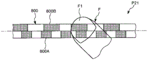
As shown in fig. 11, the line pattern 800 of the present embodiment includes: a 1 st line pattern 800A whose luminance changes at a constant 1 st period (pitch) T1; and a 2 nd line pattern 800B whose luminance is changed by a constant 2 nd period (pitch) T2 different from the 1 st period T1. The 1 st and 2 nd linear patterns 800A and 800B are arranged in the width direction of the epipolar line EL (EL') (the direction intersecting the epipolar line EL). The 1 st line pattern 800A and the 2 nd line pattern 800B are located on opposite sides with respect to the epipolar line EL. That is, the epipolar line EL is positioned along the boundary between the 1 st and 2 nd linear patterns 800A and 800B.
Here, the 2 nd period T2 is not particularly limited, but is preferably less than 2 times the 1 st period T1. When the 2 nd period T2 is 2 times or more the 1 st period T1, the 1 st line pattern 800A includes two or more periods in 1 period of the 2 nd line pattern 800B. Therefore, the accuracy of the depth analysis of the fingertip F1 described later may be lowered depending on the usage environment and the like. In addition, in the present embodiment, the 2 nd period T2 is 1.75 times the 1 st period T1. The reason will be described later.
When such a line pattern 800 is displayed on the epipolar line EL', the line pattern 800 is projected on the screen 900, and the line pattern 800 is also projected on the fingertip F1. Further, a periodic variation (pattern shift) based on the depth of the fingertip F1 occurs between the linear pattern 800 on the screen 900 and the linear pattern 800 on the fingertip F1.
The pattern determination unit 530 detects the depth of the fingertip F1 from the periodic variation, and performs touch recognition based on the detected depth. Specifically, first, a stereo parallelization image P21 shown in fig. 12 is acquired. Next, the depth analysis of the 1 st and 2 nd linear patterns 800A and 800B presented on the screen 900 is performed to detect (estimate) the depth of the position of the screen 900 overlapping with the fingertip F1, and the depth analysis of the 1 st and 2 nd linear patterns 800A and 800B presented on the fingertip F1 is performed to detect the depth of the fingertip F1.
Then, if the depth of the fingertip F1 does not match the depth of the screen 900 in at least one of the analysis result of the 1 st linear pattern 800A and the analysis result of the 2 nd linear pattern 800B, the pattern determination section 530 determines a "non-contact state" in which the fingertip F1 does not contact the screen 900. On the other hand, when the depth of the fingertip F1 matches the depth of the screen 900 in both the analysis result of the 1 st linear pattern 800A and the analysis result of the 2 nd linear pattern 800B, the pattern determination unit 530 further performs the following determination.
For example, when the 1 st line pattern 800A is described, as shown in fig. 13, even if the fingertip F1 is separated from the screen 900, when the separation mode thereof causes a period fluctuation (pattern shift) corresponding to an integral multiple of the period of the 1 st line pattern 800A, an image in which the pattern on the fingertip F1 is in the same contact state as the fingertip F1 contacts the screen 900 is obtained (hereinafter, this phenomenon is referred to as "phase wrapping"). In this regard, the same is true for the 2 nd line pattern 800B.
Therefore, if the separation method of the fingertip F1 generates a period variation corresponding to an integral multiple of the period of the 1 st line pattern 800A and a period variation corresponding to an integral multiple of the period of the 2 nd line pattern 800B, phase entanglement occurs. Therefore, it is necessary to distinguish whether the contact state or the state in which the phase winding is generated. In addition, as described above, the period of the length of the 2 nd line pattern 800B (the 2 nd period T2) is 1.75 times the period of the length of the 1 st line pattern 800A (the 1 st period T1). By adopting such a relationship, the least common multiple of the two periods can be made relatively large (i.e., 7 times of the 1 st period T1 and 4 times of the 2 nd period T2), and therefore the condition for generating the phase winding can be further reduced.
Although there is no particular limitation on the method for distinguishing whether the contact state or the phase winding state is generated, the following methods are available. That is, in the stereoscopic parallelized image in the case of the contact state, since the fingertip F1 is in contact with the screen 900, the shadow of the fingertip F1 is not generated on the screen 900. On the other hand, in the stereo-parallelized image in which the phase wrapping occurs, since the fingertip F1 is separated from the screen 900, the shadow of the fingertip F1 is generated on the screen 900. Therefore, the pattern determination unit 530 may determine that the "contact state" is generated if the shadow of the fingertip F1 is not generated on the screen 900 in the stereo-parallelized image, and the pattern determination unit 530 may determine that the "phase winding state" in which the phase winding is generated if the shadow is generated.
Further, depending on the arrangement of the projector 300 or the camera 400, the shape or size (personal difference) of the fingertip F1, and the like, a shadow may be generated on the screen 900 even in a contact state. Therefore, a threshold value may be set for the width (size) of the shadow, and if the width (size) is smaller than the threshold value, it is determined as the "contact state", and if the width (size) is equal to or larger than the threshold value, it is determined as the "phase winding state".
With this configuration, it is possible to reduce the occurrence of phase winding and perform high-precision touch recognition. Conversely, it can also be said that the generation of phase winding is suppressed, and accordingly the cycle of the 1 st and 2 nd linear patterns 800A and 800B can be shortened, and accordingly more accurate touch recognition can be performed.
The same effects as those of the above-described embodiment 1 can be obtained by embodiment 3 as well.
< embodiment 4 >
Next, an image recognition unit according to embodiment 4 of the present invention will be described.
Fig. 14 is a diagram showing a periodic pattern used in the image recognition unit of embodiment 4 of the present invention.
Although the image recognition unit according to embodiment 4 of the present invention will be described below, the description will be focused on differences from the above-described embodiments, and descriptions of similar matters will be omitted.
The image recognition unit of embodiment 4 is the same as that of embodiment 3 except that the line pattern is different. The same components as those of the above embodiment are denoted by the same reference numerals.
In the image recognition unit 100 of the present embodiment, as shown in fig. 14, the 1 st line pattern 800A and the 2 nd line pattern 800B are displayed at different timings (displayed in a time-sharing manner). Specifically, the 1 st line pattern 800A and the 2 nd line pattern 800B are alternately displayed at a predetermined period. With this configuration, since the 1 st and 2 nd linear patterns 800A and 800B can be displayed at the same position, more accurate touch recognition can be performed.
The same effects as those of the above-described embodiment 1 can be obtained by the above-described embodiment 4.
< embodiment 5 >
Next, an image recognition unit according to embodiment 5 of the present invention will be described.
Fig. 15 is a diagram showing a periodic pattern used in the image recognition unit of embodiment 5 of the present invention. Fig. 16 is a diagram showing an image of a line pattern acquired in a state where a fingertip is in contact with a screen. Fig. 17 is a diagram showing an image of a line pattern acquired in a state where a fingertip is not in contact with a screen.
Although the image recognition unit according to embodiment 5 of the present invention will be described below, the description will be focused on differences from the foregoing embodiments, and descriptions of similar matters will be omitted.
The image recognition unit of embodiment 5 is the same as that of embodiment 1 except that the line pattern is different. The same components as those of the above embodiment are denoted by the same reference numerals.
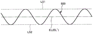
The linear pattern 800 of the present embodiment includes a line segment having a portion (non-parallel portion) inclined with respect to the epipolar line EL (EL'), and in the present embodiment, the linear pattern 800 has a sine wave shape as shown in fig. 15. The linear pattern 800 is separated from the epipolar line EL at equal distances on both sides and is located between line segments L51, L52 parallel to the epipolar line EL. That is, in the present embodiment, the peaks of the upper and lower peaks of the sine wave are located at equal distances from the epipolar line EL. The distance separating the line segments L51 and L52 is not particularly limited, but is preferably substantially equal to or greater than the width of the fingertip F1 or the width of the fingertip F1.
In this way, when the linear pattern 800 having a portion inclined with respect to the epipolar line EL is used, touch recognition can be performed in the following manner. In the stereo-parallelized image P51 in the case where the fingertip F1 is in contact with the screen 900, as shown in fig. 16, the line pattern 800 on the fingertip F1 is offset in the horizontal direction (lateral direction of the paper surface) with respect to the line pattern 800 on the screen 900, but the continuity thereof is substantially maintained. That is, the linear pattern 800 is continuous even at the boundary portion a between the screen 900 and the fingertip F1.
On the other hand, in the stereoscopic parallelized image P52 in the case where the fingertip F1 does not contact the screen 900, as shown in fig. 17, the linear pattern 800 on the fingertip F1 is largely shifted in the horizontal direction with respect to the linear pattern 800 on the screen 900, and the continuity thereof is lost. That is, the linear pattern 800 is discontinuous at the boundary portion a between the screen 900 and the fingertip F1.
Therefore, the pattern determination unit 530 can perform highly accurate touch recognition by determining the continuity of the linear pattern 800 at the boundary portion a.
The same effects as those of the above-described embodiment 1 can be obtained by the above-described embodiment 5.
The shape of the line pattern 800 is not limited to a sine wave shape as long as it has a portion (non-parallel portion) inclined with respect to the epipolar line EL, and may be, for example, a triangular wave shape, a sawtooth wave shape, or the like.
< embodiment 6 >
Next, an image recognition unit according to embodiment 6 of the present invention will be described.
Fig. 18 is a diagram showing a periodic pattern used in the image recognition unit of embodiment 6 of the present invention. Fig. 19 is a diagram illustrating a touch recognition method using the linear pattern shown in fig. 18.
Although the image recognition unit according to embodiment 6 of the present invention will be described below, the description will be focused on differences from the above-described embodiments, and descriptions of similar matters will be omitted.
The image recognition unit of embodiment 6 is the same as that of embodiment 5 described above, except that the line pattern is different. The same components as those of the above embodiment are denoted by the same reference numerals.
In the above-described embodiment 5, the case where the continuity of the linear pattern 800 is maintained even at the boundary portion a when the fingertip F1 comes into contact with the screen 900 has been described, but it is also necessary to consider a case where the continuity is lost depending on the shape or size of the fingertip F1, and in such a case, there is a possibility that erroneous touch recognition is performed. Therefore, the above-described problems can be effectively solved by using the line pattern 800 of the present embodiment.
As shown in fig. 18, the outline of the linear pattern 800 of the present embodiment has a sine wave shape, and the region S surrounded by the outline and the epipolar line EL (EL') is filled with a predetermined luminance. With such a configuration, the continuity of the contour of the region S can be easily determined from the stereo-parallelized image.
As described above, the continuity of the linear pattern 800 may be lost at the boundary portion a regardless of whether or not the fingertip F1 is in contact with the screen 900, but even in such a case, as shown in fig. 19, the variation amount (the size of discontinuity) D1 of the position of the linear pattern 800 in the case where the fingertip F1 is in contact with the screen 900 is smaller than the variation amount D2 in the case where the fingertip F1 is not in contact with the screen 900. Therefore, a certain degree of fluctuation D3 may be set as a threshold value, and the state may be determined as "contact state" if the fluctuation is smaller than the fluctuation D3, and as "non-contact state" if the fluctuation is larger than the fluctuation D3.
According to such a method, more accurate touch recognition can be performed. Further, according to the line pattern 800 of the present embodiment, even in an environment in which the surrounding environment fluctuates due to external light or the like, accurate analysis can be performed. Further, even if the period (pitch) of the linear pattern 800 is set to be relatively large, there is less possibility that the accuracy of touch recognition is lowered.
The same effects as those of the above-described embodiment 1 can be obtained by the above-described embodiment 6.
The shape of the linear pattern 800 is not limited to a sine wave shape as long as it has a component (non-parallel component) inclined with respect to the epipolar line EL, and may be, for example, a triangular wave shape, a sawtooth wave shape, or the like.
< embodiment 7 >
Next, an image recognition unit according to embodiment 7 of the present invention will be described.
Fig. 20 is a diagram showing illumination light used in the image recognition unit according to embodiment 7 of the present invention. Fig. 21 and 22 are diagrams for explaining a finger detection method using the illumination light shown in fig. 20.
Although the image recognition unit according to embodiment 7 of the present invention will be described below, the description will be focused on differences from the above-described embodiments, and descriptions of similar matters will be omitted.
The image recognition unit according to embodiment 7 is mostly the same as that according to embodiment 1 described above, except that NIR light (near infrared rays having a wavelength of about 800 to 2500 nm) is used to detect the finger F and perform touch recognition. The same components as those of the above embodiment are denoted by the same reference numerals.
In the image recognition unit 100 of the present embodiment, an NIR camera capable of capturing NIR light is used as the camera 400.
In the image recognition unit 100 of the present embodiment, the line pattern 800 irradiated by the projector 300 is generated using NIR light. In this case, the light source 310 of the projector 300 described in embodiment 1 may be changed to a configuration capable of emitting NIR laser light. By using NIR light as the line pattern 800, the image from the projector 200 is not deteriorated, and the high contrast (the difference in luminance between the 1 st area 810 and the 2 nd area 820) of the line pattern 800 can be exhibited even in an environment where external light is incident.
Further, the image recognition unit 100 includes a projector (illumination light irradiation device) 600 that irradiates illumination light LL onto a screen 900 as shown in fig. 20, in addition to the projector 200, the projector 300, the camera 400, and the image recognition device 500. The projector 600 irradiates illumination light LL composed of NIR light in such a manner as to extend over the entire area of the screen 900. The illumination light LL is used for improving the detection accuracy of the finger F as described later.
The illumination light LL is a lattice pattern in which bright lines LLa extending in the longitudinal direction of the paper (direction intersecting the linear pattern 800) are periodically arranged in the lateral direction. By using such a pattern, the illumination light LL and the line pattern 800, both of which are NIR light, can be easily distinguished. However, the pattern of the illumination light LL is not particularly limited, and for example, the bright line LLa may be inclined with respect to the linear pattern 800 or may be curved in an arc shape. Further, for example, by displaying (displaying in a time-sharing manner) the illumination light LL and the line pattern 800 at different timings, the illumination light LL and the line pattern 800 can be distinguished from each other.
Next, the function of the illumination light LL will be described. In a state where the image from the projector 200 is displayed on the screen 900, the finger F is also irradiated with light of various colors (hue, saturation, and brightness) by the light from the projector 200. Therefore, the following cases also need to be considered: it is difficult to extract a similar skin color region by the HSV color system by the measurement point determination unit 510, and the fingertip F1 cannot be determined with high accuracy. Therefore, the illumination light LL is used to improve the detection accuracy of the fingertip F1.
To explain the method of using the illumination light LL, first, an image of the illumination light LL irradiated onto the screen 900 in a state where the finger F is not present is acquired by the camera 400, and the stereo-parallelized image is stored as a reference stereo-parallelized image P71 shown in fig. 21. Then, the measurement point determination unit 510 extracts the finger F from the difference between the comparative stereo-parallelized image P72 and the reference stereo-parallelized image P71, which are obtained by the camera 400 during use and subjected to stereo-parallelization. For example, when there is a finger F in the comparative stereo-parallelized image P72, the illumination light LL on the screen 900 and the illumination light LL on the finger F are offset as shown in fig. 22, and therefore the measurement point determining unit 510 can extract the finger F from the offset (difference). The processing after the finger F is extracted (from the judgment of the fingertip F1 to the touch recognition) is the same as in the foregoing embodiment 1.
Here, the period of the illumination light LL is preferably substantially equal to the period of the line pattern 800. Thus, the pattern determination unit 530 can determine the continuity of the linear pattern 800 by comparing the reference stereo-parallelized image P71. Therefore, the continuity of the linear pattern 800 can be determined with higher accuracy.
With this configuration, the finger F can be extracted with higher accuracy without being affected by the image displayed on the screen 900 by the projector 200. Further, since NIR light invisible to humans is used as the illumination light LL, there is no possibility that the image from the projector 200 is deteriorated. In particular, when the lattice-patterned illumination light LL is used as in the present embodiment, the reference stereo-parallelized image P71 and the comparison stereo-parallelized image P72 can be compared with each other by binarizing the images, and therefore the extraction of the finger F is not easily affected by the external environment.
The configuration of the projector 600 is not particularly limited as long as illumination light LL can be emitted. For example, a configuration having a light source that emits NIR laser light and a diffraction grating that diffracts the NIR laser light emitted from the light source may be adopted, and a liquid crystal type projector, an optical scanning type projector, or a DMD type projector having a light source that can emit NIR light may be used. Further, the projector 200 may also serve as the projector 600. That is, the projector 200 may be configured to irradiate the image light and the illumination light LL. In this case, for example, the projector 200 may be configured to simultaneously irradiate red light, green light, blue light, and NIR light, or may be configured to irradiate red light, green light, blue light, and NIR light in a time-division manner. When the illumination is performed in a time-division manner, a red light, a green light, and a blue light are combined on the screen 900 to generate an image, and NIR light is used to generate the illumination light LL.
The same effects as those of the above-described embodiment 1 can be obtained by the above-described embodiment 7.
In the present embodiment, the illumination light LL having a lattice pattern is used, but may be pure illumination light LL having no pattern. That is, the illumination light LL may be uniformly irradiated to the entire area of the screen 900. Even with such illumination light LL, the finger F can be extracted according to the difference in luminance value between the finger and the screen. In particular, compared to the present embodiment, a diffraction grating or the like for generating a lattice-like pattern is not required, and the device can be simplified in this respect.
Further, in image recognition section 100 according to the present embodiment, linear pattern 800 is generated using NIR light, but linear pattern 800 may be generated using visible light. However, in this case, it is necessary to use the camera 400 capable of photographing both the NIR light and the visible light.
< embodiment 8 >
Next, an image recognition unit according to embodiment 8 of the present invention will be described.
Fig. 23 is a plan view showing illumination light used in the image recognition unit according to embodiment 8 of the present invention.
Fig. 24 is a graph showing the wavelength absorption characteristics of the substance constituting the finger.
Although the image recognition unit according to embodiment 8 of the present invention will be described below, the description will be focused on differences from the above-described embodiments, and descriptions of similar matters will be omitted.
The image recognition unit of embodiment 8 is mostly the same as that of embodiment 7, except for the structure of the illumination light. The same components as those of the above embodiment are denoted by the same reference numerals.
In the above-described embodiment 7, since the reference stereo-parallelized image P71 needs to be used for extracting the finger F, for example, when the position of the screen 900 changes or the shape of the screen 900 changes (that is, when the background of the finger F changes), the reference stereo-parallelized image P71 needs to be newly acquired every time, and the finger F cannot be extracted smoothly. That is, the aforementioned embodiment 7 exerts a particularly excellent effect in the case where the position and shape of the screen 900 are fixed. In contrast, in the present embodiment described below, since the reference stereo-parallelized image is not necessary, the finger F can be smoothly extracted even when the position of the screen 900 is changed or the shape of the screen 900 is changed.
As shown in fig. 23, the illumination light LL of the present embodiment includes: 1 st illumination light LL1 having a 1 st wavelength; and 2 nd illumination light LL2 having a 2 nd wavelength different from the 1 st wavelength. Then, the 1 st illumination light LL1 and the 2 nd illumination light LL2 are simultaneously irradiated. However, the 1 st illumination light LL1 and the 2 nd illumination light LL2 may be irradiated at different timings (in a time-sharing manner). Both the 1 st illumination light LL1 and the 2 nd illumination light LL2 are pure lights having no pattern, and are uniformly (evenly) irradiated within the irradiation region.
Further, the 1 st illumination light LL1 and the 2 nd illumination light LL2 are both NIR light, and the wavelength absorption characteristics are different based on the finger F. Fig. 24 is a graph showing the wavelength absorption characteristics of the substances constituting the finger F. As shown in this figure, for example, in the vicinity of 800nm and 1050nm, the light absorption by water and hemoglobin is smaller than the peripheral wavelength, whereas in the vicinity of 970nm, the light absorption by water and hemoglobin is larger than the peripheral wavelength. Therefore, in the present embodiment, the wavelength of the 1 st illumination light LL1 is 800nm, and the wavelength of the 2 nd illumination light LL2 is 970 nm. However, the wavelengths of the 1 st and 2 nd illumination lights LL1 and LL2 are not particularly limited as long as the wavelength absorption characteristics are different from each other, and can be appropriately set according to the structure of the object.
The camera 400 is a two-band camera capable of simultaneously acquiring the 1 st image based on the 1 st illumination light LL1 and the 2 nd image based on the 2 nd illumination light LL 2. Since the 1 st image and the 2 nd image differ from each other in the wavelength absorption characteristics described above, the measurement point determination unit 510 can extract the finger F by comparing the 1 st image and the 2 nd image. As such a method, "multispectral sensing", "hyperspectral sensing", and the like are known.
With this configuration, since the reference stereo-parallelized image as in embodiment 7 is not necessary, even when the position of the screen 900 changes or the shape of the screen 900 changes, the finger F can be extracted smoothly.
The same effects as those of the above-described embodiment 1 can be obtained by the above-described embodiment 8.
< embodiment 9 >
Next, an image recognition unit according to embodiment 9 of the present invention will be described.
Fig. 25 is a diagram showing illumination light used in the image recognition unit according to embodiment 9 of the present invention. Fig. 26 is a diagram for explaining address assignment to illumination light. Fig. 27 and 28 are diagrams for explaining the touch recognition method.
Although the image recognition unit according to embodiment 9 of the present invention will be described below, the description will be focused on differences from the above-described embodiments, and descriptions of similar matters will be omitted.
The image recognition unit according to embodiment 9 is the same as that according to embodiment 7 except that an address is set for the illumination light LL. The same components as those of the above embodiment are denoted by the same reference numerals.
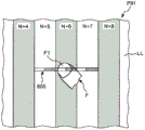
In the present embodiment, as shown in fig. 25, the period of the length of the illumination light LL (the width of the bright line LLa included in the repetitive pattern of the illumination light LL and the width between adjacent bright lines LLa) is set to be larger than the width of the fingertip F1. As shown in fig. 26, the stereo-parallelized image P91 is collated with the address image P92 prepared in advance, and an address is given to the illumination light LL in the stereo-parallelized image P91. The method of giving an address is not particularly limited, but a method of arranging a recognition pattern for each address is exemplified. The measurement point determination unit 510 determines the fingertip F1, and specifies the address at which the fingertip F1 is located, based on the given address. In the illustrated example, the fingertip F1 is located at the address [ N +6 ].
As in the stereoscopic parallelized image shown in fig. 27, the line pattern display unit 520 displays the line pattern 800 in a relatively small area including the address where the fingertip F1 is located. By displaying the line pattern 800 only in the vicinity of the address where the fingertip F1 is detected in this way, the difference determination of the line pattern 800 can be performed in a short time. Further, since the period of the line pattern 800 can be shortened, the fingertip F1 can be detected with high accuracy. In the illustrated example, the line pattern 800 is displayed at the address [ N +6] where the fingertip F1 is located and the addresses [ N +5] and [ N +7] adjacent to both sides thereof.
At this time, when the fingertip F1 touches the screen 900 or when the distance of separation from the screen 900 is short even if the fingertip F1 does not touch the screen (when the distance is within 1 cycle of the illumination light LL), the linear pattern 800 is also irradiated onto the fingertip F1. Therefore, as shown in fig. 27, the stereo-parallelized image P91 at this time is an image obtained by irradiating the fingertip F1 with the linear pattern 800. On the other hand, in the case where the fingertip F1 is not in contact with the screen 900 and the separation distance from the screen 900 is long (the case where the distance exceeds the distance corresponding to 1 cycle of the illumination light LL), the linear pattern 800 is not irradiated on the fingertip F1, and as shown in fig. 28, the stereo-parallelized image P91 is an image in which a part of the linear pattern 800 is hidden by the fingertip F1.
Such differences in images can exclude a state where the fingertip F1 is far apart from the screen 900, and only when the fingertip F1 is in contact with the screen 900 or when the distance of separation from the screen 900 is short even if the fingertip F1 is not in contact with the screen 900, the continuity of the linear pattern 800 can be determined and touch recognition can be performed. Therefore, the calculation load of touch recognition can be reduced, and highly accurate touch recognition can be performed. Further, since phase entanglement can be effectively suppressed, the period of the linear pattern 800 can be shortened, and more accurate touch recognition can be performed.
The timing of obtaining address image P92 is not particularly limited, and varies depending on the configuration of screen 900. For example, as long as the screen 900 is fixed and its shape does not change, the address image P92 may be acquired before the projector 200 performs image display. On the other hand, when the position of the screen 900 changes or the shape of the screen 900 changes, the address images P92 may be continuously acquired, and the stereo-parallelized image P91 may be addressed using the address image P92 acquired immediately before.
The same effects as those of the above-described embodiment 1 can be obtained by the above-described embodiment 9.
In the present embodiment, the illumination light LL and the line pattern 800 are generated by NIR light, but the illumination light LL and the line pattern 800 may be generated by visible light. In the case of generating the illumination light LL using visible light, the illumination light LL may be irradiated to the outside of the area where the image is displayed so that the image of the projector 200 is not deteriorated, and the address in the area may be predicted and determined from the state of the illumination light LL irradiated to the outside. Further, as described above, since the line pattern 800 is displayed only in a relatively narrow range, the image of the projector 200 is not greatly deteriorated even if the line pattern 800 is generated by visible light.
< embodiment 10 >
Next, an image recognition unit according to embodiment 10 of the present invention will be described.
Fig. 29 is a configuration diagram of a projector used in the image recognition unit according to embodiment 10 of the present invention.
Although the image recognition unit according to embodiment 10 of the present invention will be described below, the description will be focused on differences from the foregoing embodiments, and descriptions of similar matters will be omitted.
The image recognition unit according to embodiment 10 is the same as that according to embodiment 1, except that the projector 200 also serves as the projector 300. The same components as those of the above embodiment are denoted by the same reference numerals.
The projector 200 of the present embodiment has substantially the same configuration as that described in embodiment 1, but as shown in fig. 29, NIR light is incident on the liquid crystal display element 240R together with red light R. Since the difference in wavelength between red light R and NIR light is small compared to green light G and blue light B, the same optical system can be realized relatively easily. According to the projector 200 having such a configuration, the image and the line pattern 800 can be projected onto the screen 900 at the same time. In the projector 200 according to the present embodiment, the 1 st region 810 of the linear pattern 800 is composed of red light and NIR light, and the 2 nd region 820 is composed of a color different from red (NIR light off state). According to such a line pattern 800, since brightness on the screen 900 is suppressed and high contrast between the 1 st area 810 and the 2 nd area 820 is obtained, more accurate touch recognition can be performed.
The same effects as those of the above-described embodiment 1 can be obtained by the above-described embodiment 10.
The image recognition device, the image recognition method, and the image recognition unit according to the present invention have been described above with reference to the illustrated embodiments, but the present invention is not limited thereto. For example, in the image recognition apparatus of the present invention, the configuration of each part can be replaced with any configuration having the same function, and any other configuration can be added.
Description of the reference symbols
100: an image recognition unit; 200: a projector; 240B, 240G, 240R: a liquid crystal display element; 250: a dichroic prism; 260: a projection lens system; 300: a projector; 310: a light source; 311B, 311G, 311R: a light source; 312B, 312G, 312R: a collimating lens; 313: a light combining unit; 313a, 313b, 313 c: a dichroic mirror; 314: a condenser lens; 320: a scanning section; 330: a movable part; 331: a mirror; 341. 342: a shaft portion; 350: a drive frame portion; 361. 362: a shaft portion; 370: a support portion; 400: a camera; 410: a light receiving unit; 411: a lens system; 412: an image pickup element; 500: an image recognition device; 510: a measurement point determination unit; 520: a linear pattern display section; 530: a pattern determination unit; 600: a projector; 800: a line pattern; 800A: 1 st line pattern; 800B: a 2 nd line pattern; 800 a: an area; 800 b: an area; 810: region 1; 820: a 2 nd region; 900: a screen; a: a boundary portion; b: blue light; c1: a camera center; c2: an angle change center; d1, D2, D3: a variation amount; EL, EL': a nuclear line; f: a finger; f1: a fingertip; g: green light; j1, J2: a shaft; l1, l2, l 3: a straight line; l51, L52: a line segment; LL: an illumination light; LL 1: 1 st illumination light; LL 2: 2 nd illumination light; LLa: bright lines; la: image light; lb: modulating the light; p11, P21, P51, P52: stereo parallelization images; p71: a reference stereo parallelized image; p72: comparing the stereo parallelization images; p91: stereo parallelization images; p92: addressing the image; pe: checking the point; r: red light; s: an area; t1: cycle 1; t2: cycle 2; x: coordinates; e, sigma: a nuclear plane; pi 1: an image plane; and pi 2: an imaginary image plane.
Claims (13)
1. An image recognition apparatus used in an image display unit having: an imaging device that images an image display surface; and a detection image display device that displays a detection image on the image display surface, the image recognition device including:
a measurement point determination unit that detects an object located between the imaging device and the image display surface based on the image acquired by the imaging device, and determines a measurement target point of the object;
a linear pattern display unit that causes the detection image display device to display a linear pattern having a periodic pattern on an epipolar line that is determined based on a positional relationship between the imaging device and the detection image display device and that passes through the measurement target point; and
a pattern determination unit that determines, based on an image including the line pattern acquired by the imaging device, a difference between the line pattern included in the image and the line pattern when the object is not present,
the pattern determination unit determines continuity of the linear pattern, determines a contact state in which the object is in contact with the image display surface when the linear pattern has continuity, and determines a non-contact state in which the object is not in contact with the image display surface when the linear pattern does not have continuity.
2. The image recognition apparatus according to claim 1,
the line pattern has a 1 st line pattern, and the luminance of the 1 st line pattern changes according to a 1 st cycle.
3. The image recognition apparatus according to claim 1,
the line pattern has: a 1 st line pattern whose brightness changes according to a 1 st cycle; and a 2 nd line pattern whose luminance changes in a 2 nd period different from the 1 st period.
4. The image recognition apparatus according to claim 3,
displaying the 1 st and 2 nd line patterns at different times.
5. The image recognition apparatus according to claim 3,
the 1 st line pattern and the 2 nd line pattern are displayed in an array in a direction intersecting the epipolar line.
6. The image recognition apparatus according to claim 1,
the line pattern is generated using near infrared rays.
7. The image recognition apparatus according to claim 1,
the line pattern includes the following line segments: the line segment has a portion that is oblique to the epipolar line.
8. The image recognition apparatus according to claim 1,
the image display unit has an illumination light irradiation device that irradiates illumination light to the image display surface,
the measurement point determination unit detects the object from the image including the illumination light acquired by the imaging device.
9. The image recognition apparatus according to claim 8,
the illumination light has a pattern in which the luminance periodically changes along the extending direction of the epipolar line.
10. The image recognition apparatus according to claim 9,
addresses for specifying positions are assigned to the periodically changing patterns of the illumination light, respectively.
11. An image recognition method used in an image display unit having: an imaging device that images an image display surface; and a detection image display device that displays a detection image on the image display surface, the image recognition method comprising:
a measurement point determination step of detecting an object located between the imaging device and the image display surface based on the image acquired by the imaging device, and determining a measurement target point of the object;
a linear pattern display step of causing the detection image display device to display a linear pattern whose luminance periodically changes on an epipolar line that passes through the measurement target point and is determined based on a positional relationship between the imaging device and the detection image display device; and
a pattern determination step of determining, based on an image including the line pattern acquired by the imaging device, a difference between the line pattern included in the image and the line pattern when the object is not present,
the pattern determination step determines continuity of the linear pattern, determines a contact state in which the object is in contact with the image display surface when the linear pattern has continuity, and determines a non-contact state in which the object is not in contact with the image display surface when the linear pattern does not have continuity.
12. An image recognition unit, characterized in that the image recognition unit has:
the image recognition device according to any one of claims 1 to 10;
the camera device; and
the image display device for detection.
13. The image recognition unit of claim 12,
the image recognition unit has an image display device that displays an image on the image display surface.
Applications Claiming Priority (3)
| Application Number | Priority Date | Filing Date | Title |
|---|---|---|---|
| JP2016-004773 | 2016-01-13 | ||
| JP2016004773A JP6668763B2 (en) | 2016-01-13 | 2016-01-13 | Image recognition device, image recognition method, and image recognition unit |
| PCT/JP2016/088863 WO2017122534A1 (en) | 2016-01-13 | 2016-12-27 | Image recognition device, image recognition method, and image recognition unit |
Publications (2)
| Publication Number | Publication Date |
|---|---|
| CN108475145A CN108475145A (en) | 2018-08-31 |
| CN108475145B true CN108475145B (en) | 2021-06-22 |
Family
ID=59311302
Family Applications (1)
| Application Number | Title | Priority Date | Filing Date |
|---|---|---|---|
| CN201680078749.5A Active CN108475145B (en) | 2016-01-13 | 2016-12-27 | Image recognition device, image recognition method, and image recognition unit |
Country Status (4)
| Country | Link |
|---|---|
| US (1) | US10775936B2 (en) |
| JP (1) | JP6668763B2 (en) |
| CN (1) | CN108475145B (en) |
| WO (1) | WO2017122534A1 (en) |
Families Citing this family (13)
| Publication number | Priority date | Publication date | Assignee | Title |
|---|---|---|---|---|
| US11747135B2 (en) * | 2015-02-13 | 2023-09-05 | Carnegie Mellon University | Energy optimized imaging system with synchronized dynamic control of directable beam light source and reconfigurably masked photo-sensor |
| US11972586B2 (en) | 2015-02-13 | 2024-04-30 | Carnegie Mellon University | Agile depth sensing using triangulation light curtains |
| US11425357B2 (en) * | 2015-02-13 | 2022-08-23 | Carnegie Mellon University | Method for epipolar time of flight imaging |
| US11493634B2 (en) | 2015-02-13 | 2022-11-08 | Carnegie Mellon University | Programmable light curtains |
| JP6668764B2 (en) | 2016-01-13 | 2020-03-18 | セイコーエプソン株式会社 | Image recognition device, image recognition method, and image recognition unit |
| JP6631261B2 (en) | 2016-01-14 | 2020-01-15 | セイコーエプソン株式会社 | Image recognition device, image recognition method, and image recognition unit |
| JP6607121B2 (en) | 2016-03-30 | 2019-11-20 | セイコーエプソン株式会社 | Image recognition apparatus, image recognition method, and image recognition unit |
| CN108334246B (en) * | 2017-12-11 | 2021-06-22 | 北京硬壳科技有限公司 | Floating touch method and related device |
| CN111625157B (en) * | 2020-05-20 | 2021-09-17 | 北京百度网讯科技有限公司 | Fingertip key point detection method, device, equipment and readable storage medium |
| CN111811432A (en) * | 2020-06-16 | 2020-10-23 | 中国民用航空飞行学院 | Three-dimensional imaging system and method |
| CN112278801B (en) * | 2020-11-09 | 2022-03-22 | 黄河科技学院 | Control method of material sequencing system |
| KR102248504B1 (en) * | 2021-03-09 | 2021-05-06 | 시설물안전연구원 주식회사 | Apparatus for measuring a slope of object and control method thereof |
| CN114596582B (en) * | 2022-02-28 | 2023-03-17 | 北京伊园未来科技有限公司 | Augmented reality interaction method and system with vision and force feedback |
Citations (2)
| Publication number | Priority date | Publication date | Assignee | Title |
|---|---|---|---|---|
| CN101765755A (en) * | 2007-07-27 | 2010-06-30 | 欧姆龙株式会社 | Three-dimensional shape measuring device, three-dimensional shape measuring method, three-dimensional shape measuring program, and recording medium |
| JP2014115108A (en) * | 2012-12-06 | 2014-06-26 | Canon Inc | Distance measuring device |
Family Cites Families (22)
| Publication number | Priority date | Publication date | Assignee | Title |
|---|---|---|---|---|
| JPH0869515A (en) * | 1994-08-29 | 1996-03-12 | Sumitomo Electric Ind Ltd | Image display device |
| US7176440B2 (en) | 2001-01-19 | 2007-02-13 | Honeywell International Inc. | Method and apparatus for detecting objects using structured light patterns |
| US6841780B2 (en) * | 2001-01-19 | 2005-01-11 | Honeywell International Inc. | Method and apparatus for detecting objects |
| JP2004077290A (en) | 2002-08-19 | 2004-03-11 | Fuji Xerox Co Ltd | Apparatus and method for measuring three-dimensional shape |
| WO2007043036A1 (en) | 2005-10-11 | 2007-04-19 | Prime Sense Ltd. | Method and system for object reconstruction |
| JP3830956B1 (en) * | 2005-09-14 | 2006-10-11 | 健治 吉田 | Information output device |
| US9330324B2 (en) | 2005-10-11 | 2016-05-03 | Apple Inc. | Error compensation in three-dimensional mapping |
| US8050461B2 (en) | 2005-10-11 | 2011-11-01 | Primesense Ltd. | Depth-varying light fields for three dimensional sensing |
| CN101501442B (en) | 2006-03-14 | 2014-03-19 | 普莱姆传感有限公司 | Depth-varying light fields for three dimensional sensing |
| CN101496033B (en) | 2006-03-14 | 2012-03-21 | 普莱姆森斯有限公司 | Depth-varying light fields for three dimensional sensing |
| CN101739547B (en) * | 2008-11-21 | 2012-04-11 | 中国科学院沈阳自动化研究所 | Precise identification and position method of robust coding point in image under complex background |
| JP5404263B2 (en) * | 2009-09-07 | 2014-01-29 | パナソニック株式会社 | Parallax calculation method and parallax calculation device |
| JP5325814B2 (en) * | 2010-02-25 | 2013-10-23 | 大日本スクリーン製造株式会社 | Image forming apparatus and image forming method |
| EP2378394A3 (en) | 2010-04-15 | 2015-03-25 | Electronics and Telecommunications Research Institute | User interface device and method for recognizing user interaction using same |
| JP5293843B2 (en) * | 2012-01-24 | 2013-09-18 | デクセリアルズ株式会社 | Transparent conductive element, input device, electronic device and transparent conductive element manufacturing master |
| KR20140004335A (en) * | 2012-07-02 | 2014-01-13 | 한국전자통신연구원 | User interface device for projection computer and method for interfacing using the same |
| JP2014021140A (en) * | 2012-07-12 | 2014-02-03 | Seiko Epson Corp | Screen and image display system |
| JP5702411B2 (en) * | 2013-01-21 | 2015-04-15 | エヌ・ティ・ティ・コミュニケーションズ株式会社 | Remote control system, remote control method, and remote control program |
| CN105144056B (en) * | 2013-03-07 | 2018-01-23 | 三菱电机株式会社 | Display device |
| JP6668764B2 (en) | 2016-01-13 | 2020-03-18 | セイコーエプソン株式会社 | Image recognition device, image recognition method, and image recognition unit |
| JP6631261B2 (en) | 2016-01-14 | 2020-01-15 | セイコーエプソン株式会社 | Image recognition device, image recognition method, and image recognition unit |
| JP6607121B2 (en) | 2016-03-30 | 2019-11-20 | セイコーエプソン株式会社 | Image recognition apparatus, image recognition method, and image recognition unit |
-
2016
- 2016-01-13 JP JP2016004773A patent/JP6668763B2/en active Active
- 2016-12-27 US US16/068,649 patent/US10775936B2/en active Active
- 2016-12-27 WO PCT/JP2016/088863 patent/WO2017122534A1/en active Application Filing
- 2016-12-27 CN CN201680078749.5A patent/CN108475145B/en active Active
Patent Citations (2)
| Publication number | Priority date | Publication date | Assignee | Title |
|---|---|---|---|---|
| CN101765755A (en) * | 2007-07-27 | 2010-06-30 | 欧姆龙株式会社 | Three-dimensional shape measuring device, three-dimensional shape measuring method, three-dimensional shape measuring program, and recording medium |
| JP2014115108A (en) * | 2012-12-06 | 2014-06-26 | Canon Inc | Distance measuring device |
Also Published As
| Publication number | Publication date |
|---|---|
| US20190025986A1 (en) | 2019-01-24 |
| WO2017122534A1 (en) | 2017-07-20 |
| JP2017126870A (en) | 2017-07-20 |
| CN108475145A (en) | 2018-08-31 |
| US10775936B2 (en) | 2020-09-15 |
| JP6668763B2 (en) | 2020-03-18 |
Similar Documents
| Publication | Publication Date | Title |
|---|---|---|
| CN108475145B (en) | Image recognition device, image recognition method, and image recognition unit | |
| TWI513273B (en) | Scanning projectors and image capture modules for 3d mapping | |
| US10083522B2 (en) | Image based measurement system | |
| CN108463793B (en) | Image recognition device, image recognition method, and image recognition unit | |
| US9432655B2 (en) | Three-dimensional scanner based on contours from shadow images | |
| JP6037901B2 (en) | Operation detection device, operation detection method, and display control data generation method | |
| JP6037900B2 (en) | Operation detection device and operation detection method | |
| US11048363B2 (en) | Floating display device and method for a floating display device to indicate touch position | |
| US8937612B2 (en) | Coordinate locating method, coordinate locating device, and display apparatus comprising the coordinate locating device | |
| EP3531116B1 (en) | Image inspection apparatus and image inspection method | |
| US8982101B2 (en) | Optical touch system and optical touch-position detection method | |
| US20180157910A1 (en) | Gaze-tracking system and method of tracking user's gaze | |
| JP6601489B2 (en) | Imaging system, imaging apparatus, imaging method, and imaging program | |
| WO2013035553A1 (en) | User interface display device | |
| CN108475147B (en) | Image recognition device, image recognition method, and image recognition unit | |
| JP6314688B2 (en) | Input device | |
| US20170069110A1 (en) | Shape measuring method | |
| KR102495234B1 (en) | Electronic apparatus, method for controlling thereof and the computer readable recording medium | |
| JP2017125764A (en) | Object detection apparatus and image display device including the same | |
| JP2016080517A (en) | Surface inspection device | |
| KR102486540B1 (en) | Reagent analysis device and method of controlling the same | |
| US20160146592A1 (en) | Spatial motion sensing device and spatial motion sensing method | |
| JP2017021861A (en) | Projector and head mounted display device | |
| KR20240043743A (en) | Systems and methods for assigning symbols to objects | |
| JP2024065550A (en) | Pattern image output method, projector, and program |
Legal Events
| Date | Code | Title | Description |
|---|---|---|---|
| PB01 | Publication | ||
| PB01 | Publication | ||
| SE01 | Entry into force of request for substantive examination | ||
| SE01 | Entry into force of request for substantive examination | ||
| GR01 | Patent grant | ||
| GR01 | Patent grant |