JP6668764B2 - Image recognition device, image recognition method, and image recognition unit - Google Patents
Image recognition device, image recognition method, and image recognition unit Download PDFInfo
- Publication number
- JP6668764B2 JP6668764B2 JP2016004774A JP2016004774A JP6668764B2 JP 6668764 B2 JP6668764 B2 JP 6668764B2 JP 2016004774 A JP2016004774 A JP 2016004774A JP 2016004774 A JP2016004774 A JP 2016004774A JP 6668764 B2 JP6668764 B2 JP 6668764B2
- Authority
- JP
- Japan
- Prior art keywords
- pattern
- image
- image display
- image recognition
- detection
- Prior art date
- Legal status (The legal status is an assumption and is not a legal conclusion. Google has not performed a legal analysis and makes no representation as to the accuracy of the status listed.)
- Active
Links
Images


Classifications
-
- G—PHYSICS
- G06—COMPUTING; CALCULATING OR COUNTING
- G06F—ELECTRIC DIGITAL DATA PROCESSING
- G06F3/00—Input arrangements for transferring data to be processed into a form capable of being handled by the computer; Output arrangements for transferring data from processing unit to output unit, e.g. interface arrangements
- G06F3/01—Input arrangements or combined input and output arrangements for interaction between user and computer
- G06F3/03—Arrangements for converting the position or the displacement of a member into a coded form
- G06F3/041—Digitisers, e.g. for touch screens or touch pads, characterised by the transducing means
- G06F3/042—Digitisers, e.g. for touch screens or touch pads, characterised by the transducing means by opto-electronic means
- G06F3/0425—Digitisers, e.g. for touch screens or touch pads, characterised by the transducing means by opto-electronic means using a single imaging device like a video camera for tracking the absolute position of a single or a plurality of objects with respect to an imaged reference surface, e.g. video camera imaging a display or a projection screen, a table or a wall surface, on which a computer generated image is displayed or projected
-
- G—PHYSICS
- G01—MEASURING; TESTING
- G01B—MEASURING LENGTH, THICKNESS OR SIMILAR LINEAR DIMENSIONS; MEASURING ANGLES; MEASURING AREAS; MEASURING IRREGULARITIES OF SURFACES OR CONTOURS
- G01B11/00—Measuring arrangements characterised by the use of optical techniques
- G01B11/24—Measuring arrangements characterised by the use of optical techniques for measuring contours or curvatures
- G01B11/25—Measuring arrangements characterised by the use of optical techniques for measuring contours or curvatures by projecting a pattern, e.g. one or more lines, moiré fringes on the object
-
- G—PHYSICS
- G03—PHOTOGRAPHY; CINEMATOGRAPHY; ANALOGOUS TECHNIQUES USING WAVES OTHER THAN OPTICAL WAVES; ELECTROGRAPHY; HOLOGRAPHY
- G03B—APPARATUS OR ARRANGEMENTS FOR TAKING PHOTOGRAPHS OR FOR PROJECTING OR VIEWING THEM; APPARATUS OR ARRANGEMENTS EMPLOYING ANALOGOUS TECHNIQUES USING WAVES OTHER THAN OPTICAL WAVES; ACCESSORIES THEREFOR
- G03B17/00—Details of cameras or camera bodies; Accessories therefor
- G03B17/48—Details of cameras or camera bodies; Accessories therefor adapted for combination with other photographic or optical apparatus
- G03B17/54—Details of cameras or camera bodies; Accessories therefor adapted for combination with other photographic or optical apparatus with projector
-
- G—PHYSICS
- G06—COMPUTING; CALCULATING OR COUNTING
- G06F—ELECTRIC DIGITAL DATA PROCESSING
- G06F3/00—Input arrangements for transferring data to be processed into a form capable of being handled by the computer; Output arrangements for transferring data from processing unit to output unit, e.g. interface arrangements
- G06F3/01—Input arrangements or combined input and output arrangements for interaction between user and computer
- G06F3/03—Arrangements for converting the position or the displacement of a member into a coded form
- G06F3/041—Digitisers, e.g. for touch screens or touch pads, characterised by the transducing means
- G06F3/042—Digitisers, e.g. for touch screens or touch pads, characterised by the transducing means by opto-electronic means
-
- H—ELECTRICITY
- H04—ELECTRIC COMMUNICATION TECHNIQUE
- H04N—PICTORIAL COMMUNICATION, e.g. TELEVISION
- H04N9/00—Details of colour television systems
- H04N9/12—Picture reproducers
- H04N9/31—Projection devices for colour picture display, e.g. using electronic spatial light modulators [ESLM]
- H04N9/3129—Projection devices for colour picture display, e.g. using electronic spatial light modulators [ESLM] scanning a light beam on the display screen
-
- H—ELECTRICITY
- H04—ELECTRIC COMMUNICATION TECHNIQUE
- H04N—PICTORIAL COMMUNICATION, e.g. TELEVISION
- H04N9/00—Details of colour television systems
- H04N9/12—Picture reproducers
- H04N9/31—Projection devices for colour picture display, e.g. using electronic spatial light modulators [ESLM]
- H04N9/3191—Testing thereof
- H04N9/3194—Testing thereof including sensor feedback
-
- G—PHYSICS
- G06—COMPUTING; CALCULATING OR COUNTING
- G06F—ELECTRIC DIGITAL DATA PROCESSING
- G06F2203/00—Indexing scheme relating to G06F3/00 - G06F3/048
- G06F2203/041—Indexing scheme relating to G06F3/041 - G06F3/045
- G06F2203/04101—2.5D-digitiser, i.e. digitiser detecting the X/Y position of the input means, finger or stylus, also when it does not touch, but is proximate to the digitiser's interaction surface and also measures the distance of the input means within a short range in the Z direction, possibly with a separate measurement setup
Description
本発明は、画像認識装置、画像認識方法および画像認識ユニットに関するものである。 The present invention relates to an image recognition device, an image recognition method, and an image recognition unit.
プロジェクターからの画像が投影されたスクリーンに指が触れているかいないかを検知する画像認識技術として、特許文献1の技術が知られている。特許文献1の画像認識技術では、まず、スクリーン上に格子パターンの構造光を投影し、次に、前記指の位置における格子パターンの変化を撮像装置(カメラ)からの画像に基づいて確認することでタッチ認識を行っている。
As an image recognition technique for detecting whether or not a finger is touching a screen on which an image from a projector is projected, a technique disclosed in
しかしながら、特許文献1に記載の画像認識技術では、撮像装置から見たときの指の奥行き方向の位置検知精度が悪く、それに伴って、タッチ認識の精度も悪いという問題がある。
However, the image recognition technology described in
本発明の目的は、精度の高いタッチ認識を行うことのできる画像認識装置、画像認識方法および画像認識ユニットを提供することにある。 An object of the present invention is to provide an image recognition device, an image recognition method, and an image recognition unit that can perform highly accurate touch recognition.
このような目的は、下記の本発明により達成される。 Such an object is achieved by the present invention described below.
本発明の画像認識装置は、画像表示面を撮像する撮像装置と、前記画像表示面に検出用のパターンを表示する検出用画像表示装置と、を有する画像表示ユニットで用いられる画像認識装置であって、
前記検出用画像表示装置に、前記撮像装置と前記検出用画像表示装置の位置関係から決定されるエピポーラ線と交差する輝線が第1周期で配置される第1パターンと、前記エピポーラ線と交差する輝線が前記第1周期と異なる第2周期で配置される第2パターンと、を異なる時刻に表示させるパターン表示部と、
前記撮像装置と前記画像表示面との間にある対象物を検知し、前記対象物の計測対象点を判定する計測点判定部と、
前記撮像装置が取得した前記計測対象点および前記第1パターンを含む画像と、前記計測対象点および前記第2パターンを含む画像と、に基づいて前記画像表示面に対する前記計測対象点の位置を検知する位置検知部と、を有することを特徴とする。
これにより、位置検知部の検知結果に基づいて、高い精度でタッチ認識(対象物が画像表示面に接触しているか接触してないかの判断)を行うことができる。
An image recognition device of the present invention is an image recognition device used in an image display unit including: an imaging device that images an image display surface; and a detection image display device that displays a detection pattern on the image display surface. hand,
In the image display device for detection, a bright line intersecting with an epipolar line determined from a positional relationship between the imaging device and the image display device for detection intersects a first pattern arranged in a first cycle and the epipolar line. A pattern display unit for displaying, at different times, a second pattern in which bright lines are arranged in a second cycle different from the first cycle;
A measurement point determination unit that detects a target object between the imaging device and the image display surface and determines a measurement target point of the target object.
Detecting a position of the measurement target point with respect to the image display surface based on an image including the measurement target point and the first pattern acquired by the imaging device and an image including the measurement target point and the second pattern And a position detector that performs the operation.
Thereby, it is possible to perform touch recognition (determination of whether or not the object is in contact with the image display surface) with high accuracy based on the detection result of the position detection unit.
本発明の画像認識装置では、前記第2周期は、前記第1周期の2倍未満であることが好ましい。
これにより、より精度の高いタッチ認識を行うことができる。
In the image recognition device according to the aspect of the invention, it is preferable that the second cycle is less than twice the first cycle.
Thereby, more accurate touch recognition can be performed.
本発明の画像認識装置では、前記第1パターンおよび前記第2パターンは、それぞれ、前記輝線の配列方向に沿って第3周期を有する複数の領域に分割され、前記複数の領域の各々に位置を特定するアドレスが付与されていることが好ましい。
これにより、検出対象点が位置するアドレスを検知することができ、検知したアドレスに基づいて補助的なパターン(後述の第3パターン等)を表示することができる。そのため、より精度の高いタッチ認識を行うことができる。
In the image recognition device according to the aspect of the invention, the first pattern and the second pattern are each divided into a plurality of regions having a third period along the arrangement direction of the bright lines, and a position is set in each of the plurality of regions. Preferably, an address to be specified is assigned.
Thus, the address at which the detection target point is located can be detected, and an auxiliary pattern (such as a third pattern described later) can be displayed based on the detected address. Therefore, more accurate touch recognition can be performed.
本発明の画像認識装置では、前記第3周期は、前記第1周期と前記第2周期の最小公倍数に等しいことが好ましい。
これにより、フェーズ・ラッピングが生じる可能性が減り、より精度の高いタッチ認識が可能となる。
In the image recognition device according to the aspect of the invention, it is preferable that the third cycle is equal to a least common multiple of the first cycle and the second cycle.
Thereby, the possibility of occurrence of phase wrapping is reduced, and more accurate touch recognition becomes possible.
本発明の画像認識装置では、前記パターン表示部は、前記検出用画像表示装置に、前記計測対象点を通る前記エピポーラ線に沿う線状の第3パターンを、前記計測対象点が位置する前記領域を除いて表示させることが好ましい。
これにより、第3パターンによってフェーズ・ラッピングを区別することができ、より精度の高いタッチ認識が可能となる。
In the image recognition device according to the aspect of the invention, the pattern display unit may display, on the detection image display device, a linear third pattern along the epipolar line passing through the measurement target point, in the area where the measurement target point is located. It is preferable to display the information except for.
Thereby, phase wrapping can be distinguished by the third pattern, and more accurate touch recognition becomes possible.
本発明の画像認識装置では、前記パターン表示部は、前記検出用画像表示装置に、前記計測対象点が位置する前記領域および前記計測対象点が位置する前記領域と隣り合う2つの領域に跨る第3パターンを表示させることが好ましい。
これにより、フェーズ・ラッピングを区別することができ、より精度の高いタッチ認識が可能となる。
In the image recognition device according to the aspect of the invention, the pattern display unit may include, on the detection image display device, a second region that is adjacent to the region where the measurement target point is located and the two regions adjacent to the region where the measurement target point is located. It is preferable to display three patterns.
Thereby, phase wrapping can be distinguished, and more accurate touch recognition becomes possible.
本発明の画像認識装置では、前記パターン表示部は、前記検出用画像表示装置に、前記エピポーラ線と平行な方向に沿う線状パターンを有し、隣り合う前記複数の領域の前記線状パターンが前記エピポーラ線と交差する方向にずれて配置される第3パターンを表示させることが好ましい。
これにより、フェーズ・ラッピングを区別することができ、より精度の高いタッチ認識が可能となる。
In the image recognition device of the present invention, the pattern display unit has a linear pattern along a direction parallel to the epipolar line on the image display device for detection, and the linear pattern of the plurality of adjacent regions is It is preferable to display a third pattern that is displaced in a direction intersecting with the epipolar line.
Thereby, phase wrapping can be distinguished, and more accurate touch recognition becomes possible.
本発明の画像認識方法は、画像表示面を撮像する撮像装置と、前記画像表示面に検出用画像を表示する検出用画像表示装置と、を有する画像表示ユニットで用いられる画像認識方法であって、
前記検出用画像表示装置に、前記撮像装置と前記検出用画像表示装置の位置関係から決定されるエピポーラ線と交差する輝線が第1周期で配置される第1パターンと、前記エピポーラ線と交差する輝線が前記第1周期と異なる第2周期で配置される第2パターンと、を異なる時刻に表示させるパターン表示ステップと、
前記撮像装置と前記画像表示面との間にある対象物を検知し、前記対象物の計測対象点を判定する計測点判定ステップと、
前記撮像装置が取得した前記計測対象点および前記第1パターンを含む画像と、前記計測対象点および前記第2パターンを含む画像と、に基づいて前記画像表示面に対する前記計測対象点の位置を検知する位置検知ステップと、を有することを特徴とする。
これにより、位置検知部の検知結果に基づいて、高い精度でタッチ認識(対象物が画像表示面に接触しているか接触してないかの判断)を行うことができる。
An image recognition method according to the present invention is an image recognition method used in an image display unit including: an imaging device that captures an image display surface; and a detection image display device that displays a detection image on the image display surface. ,
In the image display device for detection, a bright line intersecting with an epipolar line determined from a positional relationship between the imaging device and the image display device for detection intersects a first pattern arranged in a first cycle and the epipolar line. A pattern display step of displaying, at a different time, a second pattern in which the bright lines are arranged in a second cycle different from the first cycle;
A measurement point determination step of detecting a target object between the imaging device and the image display surface and determining a measurement target point of the target object;
Detecting a position of the measurement target point with respect to the image display surface based on an image including the measurement target point and the first pattern acquired by the imaging device and an image including the measurement target point and the second pattern And a position detecting step.
Thereby, it is possible to perform touch recognition (determination of whether or not the object is in contact with the image display surface) with high accuracy based on the detection result of the position detection unit.
本発明の画像認識ユニットは、本発明の画像認識装置と、
前記撮像装置と、
前記検出用画像表示装置と、を有することを特徴とする。
これにより、高い精度でタッチ認識を行うことのできる画像認識ユニットが得られる。
An image recognition unit according to the present invention includes an image recognition device according to the present invention,
The imaging device;
And the image display device for detection.
Thus, an image recognition unit capable of performing touch recognition with high accuracy is obtained.
本発明の画像認識ユニットでは、前記画像表示面に画像を表示する画像表示装置を有することが好ましい。
これにより、画像表示面に所望の画像を表示することができる。
It is preferable that the image recognition unit of the present invention has an image display device that displays an image on the image display surface.
Thus, a desired image can be displayed on the image display surface.
以下、本発明の画像認識装置、画像認識方法および画像認識ユニットの好適な実施形態について、添付図面を参照しつつ説明する。 Hereinafter, preferred embodiments of an image recognition device, an image recognition method, and an image recognition unit of the present invention will be described with reference to the accompanying drawings.
<第1実施形態>
まず、第1実施形態に係る画像認識ユニットについて説明する。
<First embodiment>
First, an image recognition unit according to the first embodiment will be described.
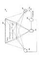
図1は、本発明の第1実施形態に係る画像認識ユニットの構成を示す図である。図2は、図1に示すプロジェクターの構成図である。図3は、図1に示すプロジェクターの構成図である。図4は、図3に示すプロジェクターが備える走査部の平面図である。図5は、図1に示す画像認識装置のブロック図である。図6は、第1パターンおよび第2パターンを示す図である。図7は、エピポーラ線について説明する図である。図8ないし図10は、それぞれ、タッチ認識の方法について説明する図である。 FIG. 1 is a diagram illustrating a configuration of an image recognition unit according to the first embodiment of the present invention. FIG. 2 is a configuration diagram of the projector shown in FIG. FIG. 3 is a configuration diagram of the projector shown in FIG. FIG. 4 is a plan view of a scanning unit provided in the projector shown in FIG. FIG. 5 is a block diagram of the image recognition device shown in FIG. FIG. 6 is a diagram showing the first pattern and the second pattern. FIG. 7 is a diagram illustrating an epipolar line. 8 to 10 are diagrams illustrating a touch recognition method.
図1に示す画像認識ユニット100は、例えば、平坦なスクリーン(画像表示面)900に指(対象物)Fが接触しているか否かを判定し、判定結果に基づいてスクリーン900に表示する画像を切り替えることのできる装置である。なお、以下では、スクリーン900に指Fが接触しているか否かの判断を「タッチ認識」と言う。このような画像認識ユニット100は、例えば、プレゼンテーションに用いることができ、プレゼンターの指のタッチ認識を行って、必要時にスクリーン900に映し出される画像を切り替えたり、拡大または縮小したりすることで、プレゼンテーションをスムーズに進行することが可能となる。
The
ただし、画像表示面としては、スクリーン900に限定されず、例えば、壁、ガラス等であってもよい。また、画像表示面は、平坦でなくてもよく、球面や凹凸面であってもよい。また、画像表示面は、経時的に形状が変化してもよい。また、タッチ認識を行う対象物としては、指Fに限定されず、例えば、指し棒、スクリーン900に吸着したマグネット等であってもよい。また、画像認識ユニット100の用途としては、プレゼンテーションに限定されず、例えば、デパート等の店舗案内、取扱商品の紹介・検索等、様々な用途に用いることができる。
However, the image display surface is not limited to the
このような画像認識ユニット100は、図1に示すように、スクリーン900に画像を表示するプロジェクター(画像表示装置)200と、スクリーン900に検出用パターンを表示するプロジェクター(検出用画像表示装置)300と、スクリーン900を撮像するカメラ(撮像装置)400と、を有する画像表示ユニットと、タッチ認識を行う画像認識装置500と、を有する。
As shown in FIG. 1, such an
プロジェクター300およびカメラ400は、異なる位置に配置されている。また、プロジェクター300およびカメラ400の相対的(幾何的)な位置関係は一定であり、位置関係に関する情報は、画像認識装置500が有する図示しない記憶部に記憶され、適宜使用される。
The
以下、プロジェクター200、プロジェクター300、カメラ400および画像認識装置500について順に説明する。
Hereinafter, the
[プロジェクター200]
プロジェクター200は、観察者に視認させたい画像(例えば、プレゼンテーション用の画像)をスクリーン900に表示する装置である。
[Projector 200]
The
このようなプロジェクター200は、LCD方式のプロジェクターであり、図2に示すように、液晶表示素子240R、240G、240Bと、ダイクロイックプリズム250と、投射レンズ系260と、を備えている。そして、液晶表示素子240Rには赤色光Rが入射し、液晶表示素子240Gには緑色光Gが入射し、液晶表示素子240Bには青色光Bが入射する。
Such a
液晶表示素子240R、240G、240Bは、それぞれR、G、Bの原色に対応する透過型の空間光変調器であり、液晶表示素子240R、240G、240Bによってそれぞれ空間的に変調された光は、ダイクロイックプリズム250で合成され、ダイクロイックプリズム250からフルカラーの映像光Laが出射される。そして、出射された映像光Laは、投射レンズ系260によって拡大されてスクリーン900に投射される。これにより、スクリーン900に画像が表示される。
The liquid
以上、プロジェクター200について説明したが、プロジェクター200としては、スクリーン900に画像を表示することができれば、LCD方式のプロジェクターに限定されず、例えば、光走査方式のプロジェクターであってもよいし、DMD方式のプロジェクターであってもよい。
The
[プロジェクター300]
プロジェクター300は、タッチ認識を行うための検出用パターンをスクリーン900に表示する装置である。
[Projector 300]
The
このようなプロジェクター300は、光走査型のプロジェクターであり、図3に示すように、光源310と、走査部320と、図示しない投射レンズ系と、を備えている。
Such a
光源310は、赤色のレーザー光を射出する光源311Rと、緑色のレーザー光を射出する光源311Gと、青色のレーザー光を射出する光源311Bと、光源311R、311G、311Bから出射された光を平行光化するコリメータレンズ312R、312G、312Bと、光合成部313と、集光レンズ314と、を有する。
The
光合成部313は、光源311R、311G、311Bからのレーザー光を合成して変調光Lbを生成する要素であり、3つのダイクロイックミラー313a、313b、313cを有する。そして、光合成部313で生成された変調光Lbは、集光レンズ314によって所望のNA(開口数)に変更された後、走査部320に導かれる。
The
走査部320は、2軸まわりに揺動可能な光スキャナーであり、図4に示すように、ミラー331を有する可動部330と、可動部330を軸J1まわりに揺動可能に支持する軸部341、342と、軸部341、342を支持する駆動枠部350と、駆動枠部350を軸J1に直交する軸J2まわりに揺動可能に支持する軸部361、362と、軸部361、362を支持する枠状の支持部370と、を有する。このような走査部320では、図示しない駆動手段によって、駆動枠部350を支持部370に対して軸J2まわりに揺動させつつ、可動部330を駆動枠部350に対して軸J1まわりに揺動させることで、ミラー331で反射した変調光Lbを2次元的に走査することができる。
The
そして、走査部320で走査された変調光Lbは、図示しない投射レンズ系によって拡大されてスクリーン900に投射される。これにより、スクリーン900に検出用パターンが表示される。
The modulated light Lb scanned by the
以上、プロジェクター300について説明したが、プロジェクター300としては、スクリーン900に検出用パターンを表示することができれば、光走査方式のプロジェクターに限定されず、例えば、LCD方式のプロジェクターであってもよいし、DMD方式のプロジェクターであってもよい。また、光走査方式のプロジェクターであっても、上記の構成に限定されず、例えば、1軸揺動型の光スキャナーを2つ用いて変調光Lbを2次走査してもよい。またプロジェクター300は、回折光学素子とレーザー光源を用いて2種類の異なる固定パターンを投影する構成でもよい。
The
[カメラ400]
カメラ400は、スクリーン900を撮像する装置である。このようなカメラ400は、例えば、RGBカメラであり、図1に示すように、レンズ系411および撮像素子412を備える受光ユニット410と、撮像素子412からの映像信号を処理する図示しない処理部と、を有する。
[Camera 400]
The
[画像認識装置]
画像認識装置500は、前述したプロジェクター300およびカメラ400を用いてタッチ認識を行う装置である。
[Image recognition device]
The
このような画像認識装置500は、図5に示すように、パターン表示部510と、計測点判定部520と、位置検知部530と、を有する。
As shown in FIG. 5, such an
パターン表示部510は、プロジェクター300に、スクリーン900上に検出用パターンを表示させる(パターン表示ステップ)。検出用パターンは、図6に示すように、第1パターン810と、第2パターン820と、を有しており、これらが交互にスクリーン900上に照射される。すなわち、第1パターン810と第2パターン820は、同時に表示されず、異なる時刻に表示される(時分割で表示される)。
The
ここで、第1、第2パターン810、820に関係するエピポーラ線ELについて簡単に説明する。エピポーラ線ELは、プロジェクター300とカメラ400の幾何的(相対的)な位置関係によって決定する線である。具体的には、図7に示すように、カメラ400のカメラ中心(レンズ系411の主点)C1と走査部320の変調光Lbを走査する際の角度変更中心(ミラー331の中心)C2とを結ぶ直線(ベースライン)l2と、プロジェクター300の仮想画像平面π2との交点をエピポーラ点Peと言い、仮想画像平面π2内においてエピポーラ点Peを通る全ての直線をエピポーラ線ELと言う。
Here, the epipolar line EL related to the first and
また、図7に示すように、指先F1がカメラ400の画像に含まれていれば、カメラ400の画像平面π1内での指先F1の座標(面内座標)xが決定される。この座標xとカメラ中心C1とを通る直線l1と直線l2とによって規定される平面をエピポーラ平面Σと言う。そして、エピポーラ平面Σと仮想画像平面π2とが交差してできる直線l3と一致するエピポーラ線ELを「エピポーラ線EL’」とした場合、エピポーラ線EL’上のどこかに指先F1が位置することになる。
As shown in FIG. 7, if the fingertip F1 is included in the image of the
なお、図6は、カメラ400で取得した画像をステレオ平行化処理(エピポーラ線水平化処理)した画像を図示したものである。そのため、全てのエピポーラ線ELが略平行となり、かつ、水平方向(紙面横方向)に延びた状態となる。
FIG. 6 illustrates an image obtained by subjecting the image acquired by the
第1パターン810は、図6に示すステレオ平行化画像のように、エピポーラ線ELと略直交する方向(鉛直方向)に延びる輝線が第1周期(ピッチ)T1で配置されたパターンである。具体的には、第1パターン810は、所定の輝度を有する第1領域811と、第1領域811とは異なる輝度を有する第2領域812と、を有し、これら領域811、812が同じ幅T1で交互に配置されたパターンである。第1領域811と第2領域812の輝度は、コントラスト比がなるべく高くなるように決定されることが好ましい。
The
一方、第2パターン820は、図6に示すステレオ平行化画像のように、エピポーラ線ELと略直交する方向(鉛直方向)に延びる輝線が第1周期T1と異なる第2周期(ピッチ)T2で配置されたパターンである。具体的には、第2パターン820は、所定の輝度を有する第1領域821と、第1領域821とは異なる輝度を有する第2領域822と、を有し、これら領域821、822が同じ幅T2で交互に配置されたパターンである。第1領域821と第2領域822の輝度は、コントラスト比がなるべく高くなるように決定されることが好ましい。
On the other hand, the
ここで、第2周期T2としては、特に限定されないが、第1周期T1の2倍未満であることが好ましい。第2周期T2を第1周期T1の2倍以上にすると、第2パターン820の1周期T2内に、第1パターン810が2周期以上含まれることになるため、使用環境等によっては、後述する指先F1の深度解析の正確性が低下するおそれがある。なお、本実施形態では、第2周期T2は、第1周期T1の1.75倍となっている。この理由については、後に説明する。
Here, the second cycle T2 is not particularly limited, but is preferably less than twice the first cycle T1. When the second period T2 is set to be twice or more the first period T1, two or more periods of the
以上、第1、第2パターン810、820について説明したが、第1、第2パターン810、820としては、上記の構成に限定されない。例えば、第1領域811、821および第2領域812、822は、それぞれ、エピポーラ線ELに対して傾斜していてもよいし、蛇行状、円弧状に湾曲していてもよい。
As described above, the first and
計測点判定部520は、カメラ400が取得した画像から、カメラ400とスクリーン900との間に位置する指Fを検知し、さらに、指Fの指先F1を計測対象点として判定する(計測点判定ステップ)。
The measurement
指先F1の判定方法としては、例えば、まず、第1パターン810を照射したスクリーン900の画像をカメラ400で取得し、この画像をステレオ平行化した画像を第1パターン基準画像として記憶する。そして、第1パターン810と共に指先F1が映るステレオ平行化画像と第1パターン基準画像との差分から指Fの輪郭を抽出し、抽出した指Fの輪郭形状から指先F1と類似の輪郭形状を有する部分を検出し、検出した部分を指先F1として判定することができる。
As a method of determining the fingertip F1, for example, first, an image of the
なお、指先の判定方法としては、これに限定されない。例えば、第1パターン基準画像の替りに、第2パターン820を照射したスクリーン900の画像をカメラ400で取得し、この画像をステレオ平行化した第2パターン基準画像を用い、第2パターン820と共に指先F1が映るステレオ平行化画像と第2パターン基準画像との差分から指Fの輪郭を抽出してもよい。また、第1パターン基準画像および第2パターン基準画像を共に用いてもよい。
The method of determining the fingertip is not limited to this. For example, instead of the first pattern reference image, an image of the
また、例えば、カメラ400が取得した画像からHSV表色系を用いて肌色類似領域(指Fの色と似ている色を持つ領域)を抽出し、さらに、抽出した肌色類似領域の輪郭形状から指先F1と類似の輪郭形状を有する部分を検出し、検出した部分を指先F1として判定してもよい。
Further, for example, a skin color similar region (a region having a color similar to the color of the finger F) is extracted from the image acquired by the
位置検知部530は、カメラ400が取得した画像に映る第1パターン810および第2パターン820に基づいて指先F1の深度(位置)を検知し、その検知結果に基づいてタッチ認識を行う(位置検知ステップ)。
The
具体的には、まず、位置検知部530は、図8に示すように、第1パターン810を照射した状態のスクリーン900の画像をカメラ400で取得し、この画像をステレオ平行化して第1画像P11を得ると共に、第2パターン820を照射した状態のスクリーン900の画像をカメラ400で取得し、この画像をステレオ平行化して第2画像P12を得る。このようにして取得した第1画像P11では、スクリーン900上の第1パターン810と、指先F1上の第1パターン810との間に、指先F1の深度に基づいた周期変動(パターンずれ)が発生している。第2画像P12についても同様である。
Specifically, first, as shown in FIG. 8, the
なお、カメラ400は、これら画像をなるべく短時間(例えば、1/120秒以内)で取得するのが好ましい。これにより、第1画像P11中の指先F1の位置と、第2画像P12中の指先F1の位置とのずれを小さくすることができ、精度の高いタッチ認識が可能となる。
Note that it is preferable that the
次に、位置検知部530は、第1画像P11を用いて、スクリーン900上に映る第1パターン810の深度解析を行って、スクリーン900の指先F1と重なる位置の深度を検知(推測)すると共に、指先F1上に映る第1パターン810の深度解析を行って、指先F1の深度を検知する。これと共に、位置検知部530は、第2画像P12を用いて、スクリーン900上に映る第2パターン820の深度解析を行って、スクリーン900の指先F1と重なる位置の深度を検知(推測)すると共に、指先F1上に映る第2パターン820の深度解析を行って、指先F1の深度を検知する。
Next, the
上記のような検知の結果、第1画像P11および第2画像P12の少なくとも一方において、指先F1の深度がスクリーン900の深度と一致していなければ、位置検知部530は、指先F1がスクリーン900に触れていない「非接触状態」と判定する。一方、第1画像P11および第2画像P12の両方において、指先F1の深度が、スクリーン900の深度と一致している場合には、位置検知部530は、さらに、次のような判定を行う。
As a result of the detection as described above, in at least one of the first image P11 and the second image P12, if the depth of the fingertip F1 does not match the depth of the
例えば、第1画像P11について説明すると、図9に示すように、指先F1がスクリーン900から離れていても、その離れ方が第1パターン810の周期の整数倍に相当する周期変動(パターンずれ)を生じさせる場合には、非接触状態であるにも関わらず、指先F1上のパターンが、指先F1がスクリーン900に接触している接触状態と同じ画像が得られてしまう(以下、この現象を「フェーズ・ラッピング」と言う)。このことは、第2画像P12についても同様である。
For example, as to the first image P11, as shown in FIG. 9, even if the fingertip F1 is separated from the
そのため、指先F1の離れ方が、第1パターン810の周期の整数倍に相当する周期変動を生じさせ、かつ、第2パターン820の周期の整数倍に相当する周期変動を生じさせる場合にはフェーズ・ラッピングが生じる。そこで、接触状態なのか、フェーズ・ラッピングが生じている状態なのかを区別する必要がある。なお、前述したように、第2パターン820の周期(第2周期T2)は、第1パターン810の周期(第1周期T1)の1.75倍である。このような関係とすることで、両周期の最小公倍数を比較的大きくすることができるため(第1周期T1の7倍、第2周期T2の4倍)、フェーズ・ラッピングが生じる条件をより低くすることができる。
Therefore, if the way the fingertip F1 separates causes a periodic variation corresponding to an integral multiple of the cycle of the
接触状態なのか、フェーズ・ラッピングが生じている状態なのかを区別する方法としては、特に限定されないが、次のような方法がある。すなわち、接触状態の場合の第1、第2画像P11、P12では、スクリーン900に指先F1が接触していることから、図9に示すように、スクリーン900上に指先F1による影が生じていない。一方で、フェーズ・ラッピングが生じている場合の第1、第2画像P11、P12では、スクリーン900から指先F1が離れていることから、図10に示すように、スクリーン900上に指先F1による影SHが生じる。そのため、位置検知部530は、第1、第2画像P11、P12中においてスクリーン900に指先F1による影が生じていなければ「接触状態」と判定し、影が生じていればフェーズ・ラッピングが生じている「フェーズ・ラッピング状態」と判定することができる。
A method for distinguishing between a contact state and a state in which phase lapping is occurring is not particularly limited, but includes the following methods. That is, in the first and second images P11 and P12 in the contact state, since the fingertip F1 is in contact with the
なお、プロジェクター300やカメラ400の配置、指先F1の形状や大きさ(個人差)等によっては、接触状態であっても、スクリーン900上に影が生じてしまう場合もある。そのため、影の幅(大きさ)に閾値を設け、閾値未満であれば「接触状態」と判定し、閾値以上であれば「フェーズ・ラッピング状態」と判定してもよい。
Note that, depending on the arrangement of the
位置検知部530は、判定結果が「接触状態」であったとき、その判定結果を図示しない制御部に送信する。この判定結果を受けた前記制御部は、プロジェクター200に対して、例えば、スクリーン900に表示されている画像を拡大または縮小する命令や、画像を切り替える命令等、指先F1の接触位置によって定められている画面操作命令を送信する。このような制御を行うことで、指先F1でスクリーン900をタッチするだけで、スクリーン900に表示される画像を操作することができるため、利便性の高い画像認識ユニット100となる。
When the determination result is “contact state”, the
以上のように、パターン表示ステップと、計測点判定ステップと、位置検知ステップと、を行うことが画像認識装置500によるタッチ認識の手順(方法)であり、この手順を所定の周期で繰り返し行うことで、タッチ認識を繰り返し行うことができる。
As described above, performing the pattern display step, the measurement point determination step, and the position detection step is a procedure (method) of touch recognition by the
このような画像認識装置500によれば、計算負荷を低減でき、かつ、精度の高いタッチ認識が可能となる。また、エピポーラ線ELは、スクリーン900の3次元的な位置や表面形状とは関係なく、プロジェクター300とカメラ400の幾何的な位置によって求まる線である。そのため、プロジェクター300とカメラ400の幾何的な位置を一度設定してしまえば、スクリーン900の位置や形状に影響されることなく、タッチ認識を行うことができる。特に、前述したように、第1、第2パターン810、820を用いることで、フェーズ・ラッピングの発生を低減しているため、精度の高いタッチ認識を行うことができる。反対に、フェーズ・ラッピングの発生が抑えられている分、第1、第2パターン810、820の周期を短くすることができ、その分、より精度の高いタッチ認識が可能となるとも言える。
According to such an
<第2実施形態>
次に、本発明の第2実施形態に係る画像認識ユニットについて説明する。
<Second embodiment>
Next, an image recognition unit according to a second embodiment of the present invention will be described.
図11は、本発明の第2実施形態に係る画像認識ユニットで用いられる照明光を示す図である。図12は、指を構成する物質の波長吸収特性を示すグラフである。 FIG. 11 is a diagram illustrating illumination light used in the image recognition unit according to the second embodiment of the present invention. FIG. 12 is a graph showing the wavelength absorption characteristics of the substance constituting the finger.
以下、本発明の第2実施形態に係る画像認識ユニットについて説明するが、前述した実施形態との相違点を中心に説明し、同様の事項はその説明を省略する。 Hereinafter, an image recognition unit according to a second embodiment of the present invention will be described, but the description will focus on differences from the above-described embodiment, and description of similar items will be omitted.
第2実施形態の画像認識ユニットは、指の抽出方法が異なること以外は、主に、前述した第1実施形態と同様である。なお、前述した実施形態と同様の構成には、同一符号を付してある。 The image recognition unit of the second embodiment is mainly the same as the above-described first embodiment except that the method of extracting a finger is different. The same components as those in the above-described embodiment are denoted by the same reference numerals.
前述した第1実施形態では、指Fの抽出に第1パターン基準画像や第2パターン基準画像を用いなければならないため、例えば、スクリーン900の位置が変化する場合や、スクリーン900形状が変化する場合(すなわち、指Fの背景が変化する場合)には、その都度、第1、第2パターン基準画像を取得し直さなければならず、指Fの抽出をスムーズに行うことができないおそれがある。すなわち、前述した第1実施形態は、スクリーン900の位置や形状が固定されている場合に特に優れた効果を発揮する。これに対して、これから述べる本実施形態では、第1パターン基準画像や第2パターン基準画像を必要としないため、スクリーン900の位置が変化する場合や、スクリーン900形状が変化する場合であっても、スムーズに指Fを抽出することができる。
In the above-described first embodiment, since the first pattern reference image and the second pattern reference image must be used to extract the finger F, for example, when the position of the
本実施形態の画像認識ユニット100は、プロジェクター200、プロジェクター300、カメラ400および画像認識装置500に加えて、さらに、図11に示すように、スクリーン900に照明光LLを照射するプロジェクター(照明光照射装置)600を有する。プロジェクター600は、スクリーン900の全域に広がるようにNIR光(800〜2500nm程度の波長を有する近赤外線)からなる照明光LLを照射する。このような照明光LLは、指Fの抽出に用いられる。
The
プロジェクター600の構成としては、照明光LLを照射することができれば特に限定されない。例えば、液晶型のプロジェクター、光走査型のプロジェクター、DMD型のプロジェクターを用いることができる。また、プロジェクター200またはプロジェクター300がプロジェクター600を兼ねていてもよい。
The configuration of
照明光LLは、図11に示すように、第1波長を有する第1照明光LL1と、第1波長と異なる第2波長を有する第2照明光LL2と、を含んでおり、第1照明光LL1と第2照明光LL2とがスクリーン900に同時に照射されるようになっている。ただし、第1照明光LL1と第2照明光LL2とが時分割で交互に照射されてもよい。また、第1照明光LL1および第2照明光LL2は、パターンを持たないベタな光であり、スクリーン900を一様(均等)に照らすようになっている。
As shown in FIG. 11, the illumination light LL includes a first illumination light LL1 having a first wavelength and a second illumination light LL2 having a second wavelength different from the first wavelength. The
また、第1照明光LL1と第2照明光LL2は、共にNIR光であり、かつ、指Fによる波長吸収特性が異なっている。図12は、指Fを構成する物質の波長吸収特性を示すグラフである。同図に示すように、例えば、800nm付近および1050nm付近では水およびヘモグロビンによる光吸収が周辺の波長に比べて少ないのに対して、970nm付近では、水およびヘモグロビンによる光吸収が周辺の波長に比べて多い。そのため、本実施形態では、第1照明光LL1の波長を800nmとし、第2照明光LL2の波長を970nmとしている。ただし、第1、第2照明光LL1、LL2の波長としては、波長吸収特性が異なっていれば特に限定されず、対象物の構成によって適宜設定することができる。 Further, the first illumination light LL1 and the second illumination light LL2 are both NIR lights, and have different wavelength absorption characteristics by the finger F. FIG. 12 is a graph showing the wavelength absorption characteristics of the substance constituting the finger F. As shown in the figure, for example, at around 800 nm and around 1050 nm, the light absorption by water and hemoglobin is smaller than the surrounding wavelengths, whereas at around 970 nm, the light absorption by water and hemoglobin is smaller than the surrounding wavelengths. Many. Therefore, in the present embodiment, the wavelength of the first illumination light LL1 is 800 nm, and the wavelength of the second illumination light LL2 is 970 nm. However, the wavelengths of the first and second illumination lights LL1 and LL2 are not particularly limited as long as the wavelength absorption characteristics are different, and can be appropriately set depending on the configuration of the object.
また、カメラ400は、第1照明光LL1による画像と、第2照明光LL2による画像を同時に取得可能な2バンドカメラである。前述した波長吸収特性の異なりから、第1照明光LL1による画像と第2照明光LL2による画像とに差が生じるため、計測点判定部520は、これらの画像を比較することで、指Fの抽出を行うことができる。このような手法は、「マルチスペクトルセンシング」、「ハイパースペクトルセンシング」等として公知である。
The
このような構成によれば、前述した第1実施形態のような第1パターン基準画像や第2パターン基準画像が必要ないため、スクリーン900の位置が変化する場合や、スクリーン900の形状が変化する場合であっても、スムーズに指Fを抽出することができる。
According to such a configuration, since the first pattern reference image and the second pattern reference image as in the above-described first embodiment are not necessary, the position of the
以上のような第2実施形態によっても、上述した第1実施形態と同様の効果を発揮することができる。 According to the above-described second embodiment, the same effects as those of the above-described first embodiment can be exhibited.
<第3実施形態>
次に、本発明の第3実施形態に係る画像認識ユニットについて説明する。
<Third embodiment>
Next, an image recognition unit according to a third embodiment of the present invention will be described.
図13は、本発明の第3実施形態に係る画像認識ユニットで用いられる検出用パターンを示す図である。図14および図15は、それぞれ、タッチ認識の方法を説明する図である。なお、図14および図15では、説明の便宜上、指に照射された第1、第2パターンの図示を省略している。 FIG. 13 is a diagram illustrating a detection pattern used in the image recognition unit according to the third embodiment of the present invention. 14 and 15 are diagrams illustrating a touch recognition method. 14 and 15, illustration of the first and second patterns irradiated on the finger is omitted for convenience of explanation.
以下、本発明の第3実施形態に係る画像認識ユニットについて説明するが、前述した実施形態との相違点を中心に説明し、同様の事項はその説明を省略する。 Hereinafter, an image recognition unit according to a third embodiment of the present invention will be described, but the description will focus on differences from the above-described embodiment, and description of similar items will be omitted.
第3実施形態の画像認識ユニットは、検出用パターンの構成が異なること以外は、前述した第1実施形態と同様である。なお、前述した実施形態と同様の構成には、同一符号を付してある。 The image recognition unit of the third embodiment is the same as the above-described first embodiment except that the configuration of the detection pattern is different. The same components as those in the above-described embodiment are denoted by the same reference numerals.
本実施形態では、図13に示すように、検出用パターンとして、さらにアドレスパターンADを用いる。アドレスパターンADは、第1、第2パターン810、820をそれぞれ第3周期T3を有する複数の領域に分割し、かつ、分割した各領域にアドレス(位置を特定する情報)を付与する機能を有する。
In the present embodiment, as shown in FIG. 13, an address pattern AD is further used as a detection pattern. The address pattern AD has a function of dividing the first and
具体的には、アドレスパターンADは、第1、第2パターン810、820の最小公倍数(第1パターン810の周期の7倍、第2パターン820の周期の4倍)に相当する第3周期を有するパターンで構成され、第1、第2パターン810、820の上下に表示される。すなわち、第1パターン810は、アドレスパターンADによって7周期毎に1つの領域に分割され、領域毎に位置が特定できるようになっている。同様に、第2パターン820は、アドレスパターンADによって4周期毎に1つの領域に分割され、領域毎に位置が特定できるようになっている。なお、1つのアドレスの幅は、指先F1の幅よりも若干大きめに設定されている。
Specifically, the address pattern AD has a third period corresponding to the least common multiple of the first and
ただし、アドレスパターンADの構成としては、上記と同様の効果を発揮することができれば、特に限定されない。例えば、アドレスパターンADは、第1、第2パターン810、820の上下の少なくとも一方に表示されていてもよい。
However, the configuration of the address pattern AD is not particularly limited as long as the same effect as described above can be exerted. For example, the address pattern AD may be displayed on at least one of the upper and lower sides of the first and
また、本実施形態では、検出用パターンとして、さらに、第3パターン700を用いる。第3パターン700は、プロジェクター300から、第1、第2パターン810、820と共に出射される。
In the present embodiment, the
第3パターン700は、指先F1を通るエピポーラ線EL(EL’)上に延びる線状のパターンである。また、この第3パターン700は、指先F1が位置しているアドレス[N+1]を除き、かつ、アドレス[N+1]の両隣のアドレス[N]、[N+2]を含むように照射される。なお、第3パターン700は、可視光で生成してもよいし、NIR光で生成してもよい。また、第3パターン700は、第1、第2パターン810、820と同時に表示してよいし、第1、第2パターン810、820と交互に(時分割で)表示してもよい。
The
このような第3パターン700を用いることで、指先F1が接触状態であるのか、フェーズ・ラッピングが生じている状態であるのかを、精度よく区別することができる。具体的には、接触状態の場合は、第3パターン700が指先F1上に照射されない。そのため、この際のステレオ平行化画像P31は、図14に示すように、アドレス[N+1]以外において、第3パターン700の連続性が維持された状態となる。また、指先F1上に第3パターン700が照射されないことから、指先F1上で第1パターン810や第2パターン820と第3パターン700とが重ならず、指先F1上の第1、第2パターン810、820を画像として認識することができる。一方、フェーズ・ラッピングが生じている場合は、第3パターン700が指先F1に照射されてしまい、指先F1に遮られて影となる部分が第3パターン700のどこかに発生する。そのため、この際のステレオ平行化画像P31は、図15に示すように、第3パターン700に影部分710が発生し、不連続な状態となる。また、指先F1上に第3パターン700が照射されることから、指先F1上で第1、第2パターン810、820と第3パターン700とが重なってしまい、指先F1上の第1、第2パターン810、820を画像として認識することが困難となる。
By using such a
このような画像の違いから、接触状態であるのか、フェーズ・ラッピングが生じている状態であるのかを、精度よく区別することができる。そのため、より精度の高いタッチ認識が可能となる。また、このようにフェーズ・ラッピングを効果的に抑制することができるため、第1、第2パターン810、820の周期を短くすることができ、より精度の高いタッチ認識が可能となる。また、ステレオ平行化画像P31では、第3パターン700が水平方向に延在しているため、画像の回析が容易となる。
From such a difference in the images, it is possible to accurately distinguish whether the state is a contact state or a state in which phase lapping is occurring. Therefore, more accurate touch recognition becomes possible. In addition, since the phase wrapping can be effectively suppressed as described above, the periods of the first and
以上のような第3実施形態によっても、上述した第1実施形態と同様の効果を発揮することができる。 According to the above-described third embodiment, the same effects as those of the above-described first embodiment can be exhibited.
<第4実施形態>
次に、本発明の第4実施形態に係る画像認識ユニットについて説明する。
<Fourth embodiment>
Next, an image recognition unit according to a fourth embodiment of the present invention will be described.
図16は、本発明の第4実施形態に係る画像認識ユニットで用いられるプロジェクターの構成図である。図17ないし図19は、それぞれ、タッチ認識の方法を説明する図である。 FIG. 16 is a configuration diagram of a projector used in the image recognition unit according to the fourth embodiment of the present invention. 17 to 19 are diagrams illustrating a touch recognition method.
以下、本発明の第4実施形態に係る画像認識ユニットについて説明するが、前述した実施形態との相違点を中心に説明し、同様の事項はその説明を省略する。 Hereinafter, an image recognition unit according to a fourth embodiment of the present invention will be described, but the description will focus on differences from the above-described embodiment, and description of similar items will be omitted.
第4実施形態の画像認識ユニットは、プロジェクター(検出用画像表示装置)の構成が異なること以外は、前述した第1実施形態と同様である。なお、前述した実施形態と同様の構成には、同一符号を付してある。 The image recognition unit of the fourth embodiment is the same as the above-described first embodiment except that the configuration of the projector (image display device for detection) is different. The same components as those in the above-described embodiment are denoted by the same reference numerals.
本実施形態のプロジェクター300は、プロジェクター200(図2参照)とほぼ同様であり、図16に示すように、液晶表示素子381R、381G、381Bと、ダイクロイックプリズム382と、投射レンズ系383と、を備えている。プロジェクター200との違いは、液晶表示素子381Rに赤色光Rと共にNIR光が入射するようになっている点である。赤色光Rは、緑色光Gおよび青色光Bと比較してNIR光と波長の差が小さいため、比較的簡単に同一の光学系を実現することができる。このような構成のプロジェクター300によれば、比較的簡単な構成で、可視光で生成された第1、第2パターン810、820と、NIR光で生成された第3パターン700とを同時に照射することができる。
The
ここで、上述のプロジェクター300を用いてNIR光で第3パターン700を照射すると、第3パターン700は、赤色として認識される(NIR光とともに赤色光Rも変調されるため)。そのため、第3パターン700によってスクリーン900上の画像が損なわれる可能性がある。そこで、スクリーン900上の画像を損なわないように、本実施形態では、図17に示すように、第3パターン700にデザイン性を付与し、第3パターン700をポインターの様に見える円環状(環状)としている。また、第3パターン700は、アドレスパターンADの3周期分(具体的には、指先F1が位置するアドレス[N+1]と、その両隣のアドレス[N]および[N+2])に跨って表示されている。また、第3パターン700の内部空間701は、指先F1が位置するアドレス[N+1]を跨いで位置している。
Here, when the
このような第3パターン700を用いることでも、指先F1が接触状態であるのか、フェーズ・ラッピングが生じている状態であるのかを、精度よく区別することができる。例えば、接触状態の場合の際のステレオ平行化画像P41は、図17に示すように、指F上にも第3パターン700が照射され、第3パターン700が全周にわたって環状に表示された状態となる。一方、1周期のフェーズ・ラッピングが生じている場合は、第3パターン700が指Fに照射されてしまい、第3パターン700には指Fに遮られて影となる部分が発生する。そのため、この際のステレオ平行化画像P41は、図18に示すように、第3パターン700の一部が影となって映る状態となる。また、2周期以上のフェーズ・ラッピングが生じている場合は、第3パターン700が指Fの裏側(スクリーン900側)に照射される。そのため、この際のステレオ平行化画像P41は、図19に示すように、第3パターン700の一部が指Fによって遮られて映る状態となる。
Even by using such a
このような画像の違いから、接触状態であるのか、フェーズ・ラッピングが生じた状態であるのかを、精度よく区別することができる。そのため、より精度の高いタッチ認識が可能となる。また、本実施形態では、第3パターン700が赤色として認識されるため、第3パターン700が著しく明るくならず、周囲との高いコントラストを発揮することができる。そのため、より精度の高いタッチ認識が可能となる。
From such a difference in the images, it is possible to accurately distinguish whether the state is the contact state or the state in which the phase wrapping has occurred. Therefore, more accurate touch recognition becomes possible. Further, in the present embodiment, since the
なお、2周期以上のフェーズ・ラッピングが生じている場合をより精度よく検知するために、例えば、第1、第2パターン810、820を所定の周期で明滅させる等して、第3パターン700の画像を取得する際に第1、第2パターン810、820が表示されないようすることが好ましい。
In order to more accurately detect a case where two or more cycles of phase wrapping have occurred, for example, the first and
以上のような第4実施形態によっても、上述した第1実施形態と同様の効果を発揮することができる。 According to the above-described fourth embodiment, the same effects as in the above-described first embodiment can be exhibited.
<第5実施形態>
次に、本発明の第5実施形態に係る画像認識ユニットについて説明する。
<Fifth embodiment>
Next, an image recognition unit according to a fifth embodiment of the present invention will be described.
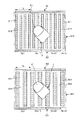
図20は、本発明の第5実施形態に係る画像認識ユニットで用いられる検出用パターンを示す図である。図21および図22は、それぞれ、タッチ認識の方法を説明する図である。 FIG. 20 is a diagram illustrating a detection pattern used in the image recognition unit according to the fifth embodiment of the present invention. FIGS. 21 and 22 are diagrams illustrating a touch recognition method.
以下、本発明の第5実施形態に係る画像認識ユニットについて説明するが、前述した実施形態との相違点を中心に説明し、同様の事項はその説明を省略する。 Hereinafter, an image recognition unit according to the fifth embodiment of the present invention will be described, but the description will focus on differences from the above-described embodiment, and description of similar items will be omitted.
第5実施形態の画像認識ユニットは、検出用パターンの構成が異なること以外は、前述した第3実施形態と同様である。なお、前述した実施形態と同様の構成には、同一符号を付してある。 The image recognition unit of the fifth embodiment is the same as the above-described third embodiment except that the configuration of the detection pattern is different. The same components as those in the above-described embodiment are denoted by the same reference numerals.
本実施形態では、図20に示すように、検出用パターンとして、第1、第2パターン810、820に加えて、第3パターン700を照射する。第3パターン700は、エピポーラ線ELと平行な方向に沿う直線状の線状パターン790を有し、この線状パターン790が縦方向(エピポーラ線ELに交差する方向)に離間して複数本(本実施形態では3本)表示されている。また、隣り合うアドレスでは、各線状パターン790が縦方向にずれている(すなわち、領域毎に不連続となっている)。なお、第3パターン700は、可視光で生成されていてもよいし、NIR光で生成されていてもよい。
In the present embodiment, as shown in FIG. 20, a
このような第3パターン700を用いることでも、指先F1が接触状態であるのか、フェーズ・ラッピングが生じている状態であるのかを、精度よく区別することができる。例えば、接触状態の場合のステレオ平行化画像P51では、図21に示すように、線状パターン790が指先F1とスクリーン900の境界部Aにおいて連続性を有している。また、指先F1がスクリーン900に接触していることから、第3パターン700上に指先F1による影が発生していない。一方、フェーズ・ラッピングが生じている場合のステレオ平行化画像P51では、図22に示すように、線状パターン790が境界部Aにおいて縦方向にずれたり、影が発生したりして不連続になっている。
Even by using such a
このような画像の違いから、接触状態であるのか、フェーズ・ラッピングが生じている状態であるのかを、精度よく区別することができる。そのため、より精度の高いタッチ認識が可能となる。 From such a difference in the images, it is possible to accurately distinguish whether the state is a contact state or a state in which phase lapping is occurring. Therefore, more accurate touch recognition becomes possible.
なお、2周期以上のフェーズ・ラッピングが生じている場合をより精度よく検知するために、例えば、第1、第2パターン810、820を所定の周期で明滅させる等して、第3パターン700の画像を取得する際に第1、第2パターン810、820が表示されないようにすることが好ましい。
In order to more accurately detect a case where two or more cycles of phase wrapping have occurred, for example, the first and
以上のような第5実施形態によっても、上述した第1実施形態と同様の効果を発揮することができる。 According to the fifth embodiment as described above, the same effects as in the first embodiment can be exerted.
以上、本発明の画像認識装置、画像認識方法および画像認識ユニットについて、図示の実施形態に基づいて説明したが、本発明はこれに限定されるものではない。例えば、本発明の画像表示装置では、各部の構成は、同様の機能を有する任意の構成のものに置換することができ、また、他の任意の構成を付加することもできる。また、前述した各実施形態を適宜組み合わせてもよい。 As described above, the image recognition device, the image recognition method, and the image recognition unit of the present invention have been described based on the illustrated embodiment, but the present invention is not limited to this. For example, in the image display device of the present invention, the configuration of each unit can be replaced with an arbitrary configuration having a similar function, and another arbitrary configuration can be added. Moreover, you may combine suitably each embodiment mentioned above.
100…画像認識ユニット、200…プロジェクター、240B、240G、240R…液晶表示素子、250…ダイクロイックプリズム、260…投射レンズ系、300…プロジェクター、310…光源、311B、311G、311R…光源、312B、312G、312R…コリメータレンズ、313…光合成部、313a、313b、313c…ダイクロイックミラー、314…集光レンズ、320…走査部、330…可動部、331…ミラー、341、342…軸部、350…駆動枠部、361、362…軸部、370…支持部、381B、381G、381R…液晶表示素子、382…ダイクロイックプリズム、383…投射レンズ系、400…カメラ、410…受光ユニット、411…レンズ系、412…撮像素子、500…画像認識装置、510…パターン表示部、520…計測点判定部、530…位置検知部、600…プロジェクター、700…第3パターン、701…内部空間、710…影部分、790…線状パターン、810…第1パターン、811…第1領域、812…第2領域、820…第2パターン、821…第1領域、822…第2領域、900…スクリーン、A…境界部、AD…アドレスパターン、B…青色光、C1…カメラ中心、C2…角度変更中心、EL、EL’…エピポーラ線、F…指、F1…指先、G…緑色光、J1、J2…軸、l1、l2、l3…直線、LL…照明光、LL1…第1照明光、LL2…第2照明光、La…映像光、Lb…変調光、P11…第1画像、P12…第2画像、P31、P41、P51…ステレオ平行化画像、Pe…エピポーラ点、R…赤色光、SH…影、T1…第1周期(幅)、T2…第2周期(幅)、T3…第3周期、x…座標、Σ…エピポーラ平面、π1…画像平面、π2…仮想画像平面 100 image recognition unit, 200 projector, 240B, 240G, 240R liquid crystal display element, 250 dichroic prism, 260 projection lens system, 300 projector, 310 light source, 311B, 311G, 311R light source, 312B, 312G , 312R: collimator lens, 313: light combining section, 313a, 313b, 313c: dichroic mirror, 314: condensing lens, 320: scanning section, 330: movable section, 331: mirror, 341, 342: axis section, 350: drive Frame part, 361, 362: Shaft part, 370: Support part, 381B, 381G, 381R: Liquid crystal display element, 382: Dichroic prism, 383: Projection lens system, 400: Camera, 410: Light receiving unit, 411: Lens system, 412: image sensor, 500: Image recognition device, 510: pattern display unit, 520: measurement point determination unit, 530: position detection unit, 600: projector, 700: third pattern, 701: internal space, 710: shadow part, 790: linear pattern, 810 .. First pattern, 811 first area, 812 second area, 820 second pattern, 821 first area, 822 second area, 900 screen, A boundary, AD address pattern, B ... Blue light, C1 ... Camera center, C2 ... Angle change center, EL, EL '... Epipolar line, F ... Finger, F1 ... Fingertip, G ... Green light, J1, J2 ... Axis, l1, l2, l3 ... Line, LL: illumination light, LL1: first illumination light, LL2: second illumination light, La: video light, Lb: modulated light, P11: first image, P12: second image, P31, P41, P51: stereo parallelization image, e: epipolar point, R: red light, SH: shadow, T1: first cycle (width), T2: second cycle (width), T3: third cycle, x: coordinate, Σ: epipolar plane, π1: image Plane, π2 ... virtual image plane
Claims (10)
前記検出用画像表示装置に、前記撮像装置と前記検出用画像表示装置の位置関係から決定されるエピポーラ線と交差する輝線が第1周期で配置される第1パターンと、前記エピポーラ線と交差する輝線が前記第1周期と異なる第2周期で配置される第2パターンと、を異なる時刻に表示させるパターン表示部と、
前記撮像装置と前記画像表示面との間にある対象物を検知し、前記対象物の計測対象点を判定する計測点判定部と、
前記撮像装置が取得した前記計測対象点および前記第1パターンを含む画像と、前記計測対象点および前記第2パターンを含む画像と、に基づいて前記画像表示面に対する前記計測対象点の位置を検知する位置検知部と、を有することを特徴とする画像認識装置。 An image recognition device used in an image display unit having an imaging device that captures an image display surface, and a detection image display device that displays a pattern for detection on the image display surface,
In the image display device for detection, a bright line intersecting with an epipolar line determined from a positional relationship between the imaging device and the image display device for detection intersects a first pattern arranged in a first cycle and the epipolar line. A pattern display unit for displaying, at different times, a second pattern in which bright lines are arranged in a second cycle different from the first cycle;
A measurement point determination unit that detects a target object between the imaging device and the image display surface and determines a measurement target point of the target object.
Detecting a position of the measurement target point with respect to the image display surface based on an image including the measurement target point and the first pattern acquired by the imaging device and an image including the measurement target point and the second pattern An image recognition device, comprising:
前記検出用画像表示装置に、前記撮像装置と前記検出用画像表示装置の位置関係から決定されるエピポーラ線と交差する輝線が第1周期で配置される第1パターンと、前記エピポーラ線と交差する輝線が前記第1周期と異なる第2周期で配置される第2パターンと、を異なる時刻に表示させるパターン表示ステップと、
前記撮像装置と前記画像表示面との間にある対象物を検知し、前記対象物の計測対象点を判定する計測点判定ステップと、
前記撮像装置が取得した前記計測対象点および前記第1パターンを含む画像と、前記計測対象点および前記第2パターンを含む画像と、に基づいて前記画像表示面に対する前記計測対象点の位置を検知する位置検知ステップと、を有することを特徴とする画像認識方法。 An image recognition method used in an image display unit having an imaging device that captures an image display surface and a detection image display device that displays a detection image on the image display surface,
In the image display device for detection, a bright line intersecting with an epipolar line determined from a positional relationship between the imaging device and the image display device for detection intersects a first pattern arranged in a first cycle and the epipolar line. A pattern display step of displaying, at a different time, a second pattern in which the bright lines are arranged in a second cycle different from the first cycle;
A measurement point determination step of detecting a target object between the imaging device and the image display surface and determining a measurement target point of the target object;
Detecting a position of the measurement target point with respect to the image display surface based on an image including the measurement target point and the first pattern acquired by the imaging device and an image including the measurement target point and the second pattern An image recognition method, comprising:
前記撮像装置と、
前記検出用画像表示装置と、を有することを特徴とする画像認識ユニット。 An image recognition device according to any one of claims 1 to 7,
The imaging device;
An image recognition unit comprising: the image display device for detection.
Priority Applications (4)
| Application Number | Priority Date | Filing Date | Title |
|---|---|---|---|
| JP2016004774A JP6668764B2 (en) | 2016-01-13 | 2016-01-13 | Image recognition device, image recognition method, and image recognition unit |
| US16/068,635 US11016613B2 (en) | 2016-01-13 | 2017-01-10 | Image recognition device, image recognition method and image recognition unit |
| CN201780006323.3A CN108463793B (en) | 2016-01-13 | 2017-01-10 | Image recognition device, image recognition method, and image recognition unit |
| PCT/JP2017/000480 WO2017122634A1 (en) | 2016-01-13 | 2017-01-10 | Image recognition device, image recognition method, and image recognition unit |
Applications Claiming Priority (1)
| Application Number | Priority Date | Filing Date | Title |
|---|---|---|---|
| JP2016004774A JP6668764B2 (en) | 2016-01-13 | 2016-01-13 | Image recognition device, image recognition method, and image recognition unit |
Publications (3)
| Publication Number | Publication Date |
|---|---|
| JP2017126182A JP2017126182A (en) | 2017-07-20 |
| JP2017126182A5 JP2017126182A5 (en) | 2018-12-27 |
| JP6668764B2 true JP6668764B2 (en) | 2020-03-18 |
Family
ID=59311323
Family Applications (1)
| Application Number | Title | Priority Date | Filing Date |
|---|---|---|---|
| JP2016004774A Active JP6668764B2 (en) | 2016-01-13 | 2016-01-13 | Image recognition device, image recognition method, and image recognition unit |
Country Status (4)
| Country | Link |
|---|---|
| US (1) | US11016613B2 (en) |
| JP (1) | JP6668764B2 (en) |
| CN (1) | CN108463793B (en) |
| WO (1) | WO2017122634A1 (en) |
Families Citing this family (5)
| Publication number | Priority date | Publication date | Assignee | Title |
|---|---|---|---|---|
| JP6668763B2 (en) | 2016-01-13 | 2020-03-18 | セイコーエプソン株式会社 | Image recognition device, image recognition method, and image recognition unit |
| JP6631261B2 (en) | 2016-01-14 | 2020-01-15 | セイコーエプソン株式会社 | Image recognition device, image recognition method, and image recognition unit |
| JP6607121B2 (en) | 2016-03-30 | 2019-11-20 | セイコーエプソン株式会社 | Image recognition apparatus, image recognition method, and image recognition unit |
| JPWO2020095739A1 (en) * | 2018-11-06 | 2021-10-07 | ソニーグループ株式会社 | Information processing equipment, information processing methods, and programs |
| JP2021197028A (en) * | 2020-06-17 | 2021-12-27 | セイコーエプソン株式会社 | Position detection method, method for controlling projector, position detection device, and projector |
Family Cites Families (21)
| Publication number | Priority date | Publication date | Assignee | Title |
|---|---|---|---|---|
| WO2004001332A1 (en) * | 2002-06-19 | 2003-12-31 | Canesta, Inc. | System and method for determining 3-d coordinates of a surface using a coded array |
| JP2004077290A (en) | 2002-08-19 | 2004-03-11 | Fuji Xerox Co Ltd | Apparatus and method for measuring three-dimensional shape |
| US8400494B2 (en) | 2005-10-11 | 2013-03-19 | Primesense Ltd. | Method and system for object reconstruction |
| US8390821B2 (en) | 2005-10-11 | 2013-03-05 | Primesense Ltd. | Three-dimensional sensing using speckle patterns |
| US9330324B2 (en) | 2005-10-11 | 2016-05-03 | Apple Inc. | Error compensation in three-dimensional mapping |
| CN101957994B (en) | 2006-03-14 | 2014-03-19 | 普莱姆传感有限公司 | Depth-varying light fields for three dimensional sensing |
| JP5592070B2 (en) | 2006-03-14 | 2014-09-17 | プライム センス リミティド | Light field that changes depth for 3D detection |
| JP2009031150A (en) * | 2007-07-27 | 2009-02-12 | Omron Corp | Three-dimensional shape measuring device, three-dimensional shape measurement method, three-dimensional shape measurement program, and record medium |
| JP5423222B2 (en) * | 2009-08-07 | 2014-02-19 | ソニー株式会社 | Position detection apparatus and position detection method |
| EP2378394A3 (en) * | 2010-04-15 | 2015-03-25 | Electronics and Telecommunications Research Institute | User interface device and method for recognizing user interaction using same |
| JP2011257336A (en) * | 2010-06-11 | 2011-12-22 | Seiko Epson Corp | Optical position detection device, electronic apparatus and display device |
| US8537376B2 (en) * | 2011-04-15 | 2013-09-17 | Faro Technologies, Inc. | Enhanced position detector in laser tracker |
| JP4997406B1 (en) * | 2011-06-16 | 2012-08-08 | レーザーテック株式会社 | Shape measuring device, depth measuring device and film thickness measuring device |
| KR20140004335A (en) * | 2012-07-02 | 2014-01-13 | 한국전자통신연구원 | User interface device for projection computer and method for interfacing using the same |
| MX2015004575A (en) * | 2012-10-10 | 2016-07-06 | Broadcast 3Dtv Inc | System for distributing auto-stereoscopic images. |
| JP2014115108A (en) * | 2012-12-06 | 2014-06-26 | Canon Inc | Distance measuring device |
| US9335547B2 (en) * | 2013-03-25 | 2016-05-10 | Seiko Epson Corporation | Head-mounted display device and method of controlling head-mounted display device |
| US10812694B2 (en) * | 2013-08-21 | 2020-10-20 | Faro Technologies, Inc. | Real-time inspection guidance of triangulation scanner |
| JP6668763B2 (en) | 2016-01-13 | 2020-03-18 | セイコーエプソン株式会社 | Image recognition device, image recognition method, and image recognition unit |
| JP6631261B2 (en) | 2016-01-14 | 2020-01-15 | セイコーエプソン株式会社 | Image recognition device, image recognition method, and image recognition unit |
| JP6607121B2 (en) | 2016-03-30 | 2019-11-20 | セイコーエプソン株式会社 | Image recognition apparatus, image recognition method, and image recognition unit |
-
2016
- 2016-01-13 JP JP2016004774A patent/JP6668764B2/en active Active
-
2017
- 2017-01-10 US US16/068,635 patent/US11016613B2/en active Active
- 2017-01-10 WO PCT/JP2017/000480 patent/WO2017122634A1/en active Application Filing
- 2017-01-10 CN CN201780006323.3A patent/CN108463793B/en active Active
Also Published As
| Publication number | Publication date |
|---|---|
| US20190025985A1 (en) | 2019-01-24 |
| CN108463793A (en) | 2018-08-28 |
| JP2017126182A (en) | 2017-07-20 |
| US11016613B2 (en) | 2021-05-25 |
| CN108463793B (en) | 2021-02-26 |
| WO2017122634A1 (en) | 2017-07-20 |
Similar Documents
| Publication | Publication Date | Title |
|---|---|---|
| JP6668763B2 (en) | Image recognition device, image recognition method, and image recognition unit | |
| JP6668764B2 (en) | Image recognition device, image recognition method, and image recognition unit | |
| US7627196B2 (en) | Image processing device and image capturing device | |
| US20150054918A1 (en) | Three-dimensional scanner | |
| US11475583B2 (en) | Depth sensing systems and methods | |
| US20170339378A1 (en) | Projection apparatus and interface apparatus | |
| JP6601489B2 (en) | Imaging system, imaging apparatus, imaging method, and imaging program | |
| JP6631261B2 (en) | Image recognition device, image recognition method, and image recognition unit | |
| JP2013069272A (en) | User interface display device | |
| US20050110868A1 (en) | System and method for inputting contours of a three-dimensional subject to a computer | |
| JP5375479B2 (en) | Three-dimensional measurement system and three-dimensional measurement method | |
| JP2016008837A (en) | Shape measuring method, shape measuring device, structure manufacturing system, structure manufacturing method, and shape measuring program | |
| JP2022143840A (en) | Optical inspection method, optical inspection device, and optical inspection program | |
| JP2013044669A (en) | Method and device for measuring surface shape | |
| JP2021018414A5 (en) | ||
| JP2020148646A (en) | Phase determination method and measuring device | |
| JP2018029304A (en) | Virtual image display system, virtual image display device and virtual image display method | |
| JP2018107489A (en) | Input/output device, information sharing method and information sharing program |
Legal Events
| Date | Code | Title | Description |
|---|---|---|---|
| A521 | Written amendment |
Free format text: JAPANESE INTERMEDIATE CODE: A523 Effective date: 20181114 |
|
| A621 | Written request for application examination |
Free format text: JAPANESE INTERMEDIATE CODE: A621 Effective date: 20181114 |
|
| TRDD | Decision of grant or rejection written | ||
| A01 | Written decision to grant a patent or to grant a registration (utility model) |
Free format text: JAPANESE INTERMEDIATE CODE: A01 Effective date: 20200128 |
|
| A61 | First payment of annual fees (during grant procedure) |
Free format text: JAPANESE INTERMEDIATE CODE: A61 Effective date: 20200210 |
|
| R150 | Certificate of patent or registration of utility model |
Ref document number: 6668764 Country of ref document: JP Free format text: JAPANESE INTERMEDIATE CODE: R150 |