JP2014115108A - Distance measuring device - Google Patents
Distance measuring device Download PDFInfo
- Publication number
- JP2014115108A JP2014115108A JP2012267556A JP2012267556A JP2014115108A JP 2014115108 A JP2014115108 A JP 2014115108A JP 2012267556 A JP2012267556 A JP 2012267556A JP 2012267556 A JP2012267556 A JP 2012267556A JP 2014115108 A JP2014115108 A JP 2014115108A
- Authority
- JP
- Japan
- Prior art keywords
- pattern
- unit
- pattern light
- imaging
- target object
- Prior art date
- Legal status (The legal status is an assumption and is not a legal conclusion. Google has not performed a legal analysis and makes no representation as to the accuracy of the status listed.)
- Pending
Links
Images


Landscapes
- Length Measuring Devices By Optical Means (AREA)
- Image Processing (AREA)
- Image Analysis (AREA)
Abstract
Description
本発明は、対象物体の3次元形状を計測する技術に関する。 The present invention relates to a technique for measuring a three-dimensional shape of a target object.
計測対象物体の三次元形状を非接触で計測する手法として、投影装置と撮像装置を用いた手法が一般的である。具体的には、縞パターンを投影し、撮像画像で撮像した画像縞パターンの投影装置上での位置を特定し、三角測量の原理で、三次元形状を求める手法が一般的である。 As a technique for measuring the three-dimensional shape of a measurement target object in a non-contact manner, a technique using a projection device and an imaging device is common. Specifically, it is common to project a fringe pattern, specify the position of the image fringe pattern captured by the captured image on the projection device, and obtain a three-dimensional shape based on the principle of triangulation.
このような三次元計測手法において、計測対象物体物が金属部品などの光沢を有する場合、計測対象物体物の形状によっては、他の面に投影されたパターン光が計測対象物体物間で複数回の反射、すなわち、多重反射が起こる。多重反射は計測対象物体物間で相互に発生するため、相互反射とも呼ばれる。多重反射が起こると計測対象物体物中に本来は存在しないはずの映り込みが生じる。このような撮影画像に基づいて、三次元計測処理を適用すると、映り込みがノイズとして認識されるため、計測精度が低下する可能性がある。 In such a three-dimensional measurement method, when the measurement target object has a gloss such as a metal part, the pattern light projected on the other surface may be projected several times between the measurement target objects depending on the shape of the measurement target object. Reflection, that is, multiple reflection occurs. Since multiple reflection occurs mutually between objects to be measured, it is also called mutual reflection. When multiple reflection occurs, a reflection that should not originally exist in the object to be measured occurs. When a three-dimensional measurement process is applied based on such a photographed image, the reflection is recognized as noise, which may reduce the measurement accuracy.
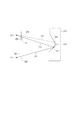
ここで、多重反射により、誤った三次元形状を推定してしまう問題について図2を用いて詳細に説明する。図2において、201は、撮像装置の主点、202は撮像素子である。撮像素子202は物理的に撮像素子202の位置には置かれないが、像を反転させないために便宜上202の位置に配置して説明する。また、204は投影装置の主点であり、203は投影素子である。投影素子203の配置位置も撮像素子202と同一の理由で203の位置に配置した。ここで投影素子203上に三次元計測する為の縞パターン205を表示する。縞パターンを複数投影する三次元計測機も存在するが、今回は説明の為に簡略化し、縞パターン205のみ表示する。縞パターン205により生じた光は、直線206の方向に進み、計測対象物体213上の面207で反射する。面207で拡散反射した光は直線209の方向に進み撮像素子202上の210の位置で結像する。また、面207上で鏡面反射した光は直線214の方向に進み、面208でさらに反射し、直線211の方向に進み、撮像素子202上の212の位置で結像する。本来であれば、210の位置に結像した像で三次元形状を推定すべきであるが、210と212の位置のどちらが多重反射によって生じた像であるか分からない為、撮像素子上で212の位置に結像した像を三次元形状復元してしまった場合は、計測対象物体213の形状とは異なる形状を推定してしまう。
Here, the problem of estimating an incorrect three-dimensional shape due to multiple reflection will be described in detail with reference to FIG. In FIG. 2, 201 is the principal point of the image pickup apparatus, and 202 is an image sensor. Although the
特許文献1では、縞模様の周期(ピッチ)が互いに異なる2種類の異なるパターン光を投影し、それぞれから三次元形状を求め、2つの三次元計測結果に乖離がある領域を、多重反射が発生した領域であると見なし、光線追跡によって多重反射を引き起こす原因となっている面を見つけ出し、その面に対応するパターン光を消光し、新たに消光したパターンを計測対象物体物に投影して得られた撮影画像に基づいて、三次元計測結果を補正している。
In
しかしながら、上記の構成では、多重反射の原因となっているパターン光部分を見つけ出すために光線追跡を行っており、処理が複雑で時間がかかってしまう。
本発明は、以上の課題に鑑みてなされた発明であり、撮影枚数を増やすことなく、多重反射の影響を低減させ、距離を精度よく計測することを目的とする。
However, in the above configuration, ray tracing is performed in order to find the pattern light portion that causes multiple reflection, and the processing is complicated and takes time.
The present invention has been made in view of the above problems, and it is an object of the present invention to reduce the influence of multiple reflection without increasing the number of shots and accurately measure the distance.
上記の目的を達成するために、本発明に係る距離計測装置は、例えば、対象物体にパターン光を投影する投影手段と、前記パターン光が投影された前記対象物体を撮像する撮像手段と、前記撮像手段で撮像された画像に基づいて、前記投影手段または前記撮像手段から、前記計測対象物体までの距離計測を行う計測手段と、前記投影手段と前記撮像手段との位置関係に基づいて、前記投影手段が投影するパターン光を決定する決定手段とを備える。 In order to achieve the above object, a distance measuring device according to the present invention includes, for example, a projection unit that projects pattern light onto a target object, an imaging unit that images the target object onto which the pattern light is projected, Based on the image captured by the image capturing unit, the measuring unit that measures the distance from the projection unit or the image capturing unit to the measurement target object, and the positional relationship between the projecting unit and the image capturing unit, Determining means for determining the pattern light to be projected by the projecting means.
本発明によれば、撮影枚数を増やすことなく、多重反射の影響を軽減し、距離を精度よく計測することができる。 According to the present invention, the influence of multiple reflection can be reduced and the distance can be accurately measured without increasing the number of shots.
以下、添付図面を参照して本発明の実施形態について詳細に説明する。 Hereinafter, embodiments of the present invention will be described in detail with reference to the accompanying drawings.
[第1の実施形態]
まず、図3を用いて、撮像装置と投影装置を用いた、一般的な三次元計測手法である空間符号化法について説明する。図3において、距離計測装置は、撮像部101、投影部102で構成される。
[First Embodiment]
First, a spatial encoding method that is a general three-dimensional measurement method using an imaging device and a projection device will be described with reference to FIG. In FIG. 3, the distance measuring device includes an
撮像部101は、例えば、産業用カメラであり、計測対象物体108を撮像する。投影部102は、例えばレーザープロジェクタや液晶プロジェクタなどのパターン光を投影可能な装置であり、パターン光群302の様な複数のパターンを投影可能な装置である。
The
距離計測の手順としては、投影部102は、パターン光群302から、パターン光303、304のような空間を分割するように明部と暗部を配置したパターン光を投影する。図中では、明部を1、暗部を0として表現している。パターン光303、304を時系列で計測対象物体108に対して投影する。ここで説明の為に、計測対象物体108の材質は、多重反射の影響が少ない計測対象物体であるとする。そして、ぞれぞれのパターン光に対して、撮像部101で撮影する。その結果、符号列305、306のような符号列が得られる。符号列305、306をデコードすると、307のような投影部102における、パターン光の位置を表した値に変換できる。つまり、計測対象物体108上の点301のように、投影部102と撮像部101の計測対象物体108上のそれぞれの投影像と撮像された画像が対応づけられ三角測量が可能になる。
As a distance measurement procedure, the
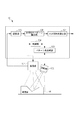
図1を参照して、本実施形態に係る距離計測装置10の構成を説明する。
With reference to FIG. 1, the structure of the distance measuring
本実施形態に係る距離計測装置10は、撮像部101と、投影部102と、パターン光生成部103と、制御部104と、記憶部105と、多重反射パターン除去部106と、距離算出部107とを備える。
The
撮像部101は、光学系と撮像素子とを有し、計測対象物体108を撮像する。また、撮像部101は、撮像した画像を記憶部105に出力する。また、撮像部101は、投影部102の投影方向とは異なる方向から計測対象物体108を撮像する。
The
投影部102は、パターン光生成部103から入力されるパターン光の情報に基づいて、計測対象物体108へパターン光を投影する。投影部102は、レーザープロジェクタや液晶プロジェクタなどのパターン光を投影可能な装置であり、パターン光を投影可能であれば投影部102の構成は限定されない。
The
パターン光生成部103は、制御部104の制御情報に基づいて、パターン光を生成し、投影部102を制御し、計測対象物体108にパターンを投影する。
The pattern
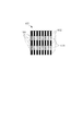
ここで、パターン光生成部103で投影するパターン光について詳細に説明する。本実施形態で投影するパターン光は図4のパターン光401のようなパターンである。一般的に空間符号化を用いた計測手法における、パターン光402のような、パターン光全面に縞パターン405が配置されている。対して、本実施形態のパターン光401は、エピポーラ線404に基づいて、縞パターン403の強度が異なるパターンを用いる。
Here, the pattern light projected by the pattern
ここで、撮像部と投影部の位置関係によって定められるエピポーラ拘束によって決定するエピポーラ線について、図5を用いて説明する。図5において、503は撮像部の主点であり、501は撮像素子である。また、504は投影部の主点であり、502は投影素子である。加えて、506は三次元空間で任意に選択した、三次元点である。ここで、撮像部主点503、投影部主点504、三次元点506がなす平面が509が定義できる。平面509が撮像素子501と交わる事で定義される線が撮像側のエピポーラ線507である。
Here, epipolar lines determined by epipolar constraints determined by the positional relationship between the imaging unit and the projection unit will be described with reference to FIG. In FIG. 5,
また、平面509が投影素子502と交わる事で定義される線が投影側のエピポーラ線508である。ここで、投影側のエピポーラ線508に配置されたパターンは、撮像部主点503、投影部主点504、三次元点506がなす平面上の三次元点であれば、撮像素子501内において撮像側のエピポーラ線507で撮像される事が分かる。本発明はこの原理を用いて、多重反射の影響を軽減する。
A line defined by the
図4に戻り、図4では、エピポーラ線404を図示しているが、実際投影するパターンには表示されない。加えて、縞パターン403は、厳密にエピポーラ線に平行である必要はなく、略平行であればよい。さらにエピポーラ線404に基づいて、光の強度が異なる状態で投影される縞パターン403は、距離計測が可能なパターンであれば、本実施形態の投影パターンである必要はない。例えば、グリッドパターンでも良いし、正弦波パターンでも良い。
Returning to FIG. 4, the
続いて、パターン光401を用いることで、多重反射の影響を軽減できる理由を図6(a)(b)を用いて説明する。 Next, the reason why the influence of multiple reflection can be reduced by using the pattern light 401 will be described with reference to FIGS.
まず、図6(a)を用いて、従来のパターン光による問題点について説明する。図6において、602はパターン光であり、603は計測用の縞パターンである。図6のパターン光402は、図4の402のような複数の縞を用いるパターンでもよいが、説明の為に単数の縞で構成された縞パターン603を用いて説明する。パターン光602を計測対象物体に対して投影し、撮像した画像は、601のような画像が撮像される。撮像された画像601には、縞パターン603が計測対象物体の表面で直接反射して撮像されたパターン604と、計測対象物体108の表面が凹面であり、凹面の中央605を中心に、多重反射によって鏡像が撮像されたパターン606が撮像されている。ここで、撮像されたパターン604と606は、撮像された時点で分離が困難である為、撮像されたパターン604と606を用いて三次元計測した場合、撮像されたパターン606は、ノイズとして作用し本来の計測対象物体の形状ではない形状情報を出力してしまう。
First, the problem with the conventional pattern light will be described with reference to FIG. In FIG. 6, reference numeral 602 denotes a pattern light, and
次に、本実施形態のパターン光が多重反射の影響を軽減できる事を、図6(b)を用いて説明する。 Next, the fact that the pattern light of this embodiment can reduce the influence of multiple reflection will be described with reference to FIG.
パターン光608は本実施のパターン光401のように複数の縞のパターンでもよいが、説明の為に単数の縞610で構成されたパターン光608を用いて説明する。ここで、607は撮像部101で撮像した画像であり、609はエピポーラ線である。
The pattern light 608 may be a pattern of a plurality of stripes as in the
また、撮像画像607において、パターン光608が計測対象物体の表面で直接反射して撮像されたパターン614と、計測対象物体108の表面が凹面であり、凹面の中央605を中心に、多重反射によって鏡像が撮像されたパターン611が撮像される。
Further, in the captured
パターン611は異なる模様のパターン612と613で構成されているが、説明の為に付与した模様であり、実際に撮像されたパターンに模様が付与されているわけではない。ここで、パターン光608と撮像画像607は、エピポーラ線609により分割されている。
The
つまり、撮像画像607において、計測対象物体108の表面で直接反射して撮像されたパターン614が撮像されている領域は、あらかじめ、エピポーラ線609で区切られた領域内である事が事前に判断できる。ここで、撮像された縞パターン612は、エピポーラ線609で区切られた領域において、縞パターン610が存在しない領域であるから、撮像された縞パターン612は計測対象物体の表面で多重反射して撮像されたパターンであると特定する事ができる。よって縞パターンは距離計測の対象から外す事が可能となる。
In other words, in the captured
また、縞パターン613は、計測対象物体108の表面で多重反射して撮像されたパターンであるが、エピポーラ線609で区切られる領域が、パターン光610と同一の領域の為、距離計測の対象から外す事はできない。よって、誤った距離計測結果を出力してしまう。以上より、本手法のパターン光は、撮像された縞パターン612,613のように撮像画像から除去可能なパターンと、除去不可能な縞パターンに分けられる。
The
つまり撮像画像から縞パターン612を除去可能であり、除去不可能な縞パターン613は限定的であるため、従来のパターン光よりも(図6(a))本実施形態のパターン光が多重反射の影響を軽減できる。ここで、本発明は、撮像部と投影部の位置関係によって定められるエピポーラ拘束に基づいて、撮像画像中のパターンが、計測対象物体の表面で多重反射して撮像されたパターンであるが、計測対象物体の表面で直接反射して撮像されたパターンであるか判断するが、他の手法で計測対象物体の表面で多重反射して撮像されたパターンであるか、計測対象物体の表面で直接反射して撮像されたパターンであるか判断できれば、その手法と組み合わせて判断しても良い。例えば、三次元計測可能な装置を複数配置し、複数配置した三次元計測可能な装置の距離の傾向から、計測対象物体の表面で多重反射して撮像されたパターンであるか、計測対象物体の表面で直接反射して撮像されたパターンであるか判断しても良い。また、計測対象物体の表面で直接反射して撮像されたパターンであるか判断できれば、該当部分のパターンを消光または減光し、再度パターンを投射しても良い。
That is, since the
本実施形態のパターン光生成部103は、複数のパターン光を時系列に切り替え投影するためのパターン光も生成可能である。図7を用いて本実施形態のパターン光の一例を説明する。
The pattern
パターン光生成部103が生成するパターン光はパターン群701のようなパターンでも良い。パターン群701はパターン光702〜706を用いて撮像空間を随時ニ分割するパターン光である。本発明のパターンはパターン群701のようなパターンに対して、パターン光702〜706何れのパターンをエピポーラ拘束に基づいて一部の光の強度を異なる状態にさせても良いが、図7ではパターン光706を分割する例を説明する。パターン光706はパターン光401のようにエピポーラ線404を基準に光の強度を異なる状態にさせている。なお、ここでいうパターン光の強度の変更とは、投影部の有する画素の輝度を変更(減光、消光、増光などを含む)することによって制御される。
The pattern light generated by the pattern
ここで図8を用いて、本発明のパターン光生成部103から投影するパターンは、複数のパターンを投影する事で、距離計測が可能な範囲を拡大可能であることについて説明する。パターン光生成部103から投影するパターンは、図8のパターン光801のような、パターン光を投影しても良い。パターン光801はパターン光401の縞パターン403に対してエピポーラ線404で区切られる領域において、縞パターン403の強度が異なる領域に縞パターン802を配置している。このように配置することで、パターン光401で距離計測が不可能な領域を、パターン光801で補間し、距離計測が可能な範囲を拡大する事が可能である。
Here, it will be described with reference to FIG. 8 that the pattern projected from the pattern
図1に戻り、制御部104は、パターン光生成部103によるパターンの投影タイミングを制御する。また、制御部104は、投影部102がパターンの投影を開始するタイミングに基づいて、撮像を開始するように撮像部101を制御する。
Returning to FIG. 1, the
記憶部105は、撮像部101から取得した撮像画像を記憶するメモリである。そしてその撮像画像を多重反射パターン除去部106へ出力する。
The
多重反射パターン除去部106は、記憶部105から取得した撮像画像から、多重反射によって生じたパターンを一部もしくは物体形状やパターン光に応じては全て除去する。ここで多重反射によって生じたパターンの除去方法について図6(b)を用いて説明する。
The multiple reflection
図6(b)の多重反射によって生じたパターン611において、除去可能なパターンは612のようなエピポーラ線609によって分割されたパターン光において計測用パターン610が存在しない領域のパターンである。ここで、多重反射によって生じたパターンの除去は撮像画像607においてパターン612を撮像画像上から削除しても良いし、距離の算出時にパターン612が存在する領域を無視して、算出しても良い。
In the
図1に戻り、距離算出部107は、多重反射パターン除去部106から入力されたパターンに基づいて、撮像部101により撮像される縞パターンの位置と、投影部102により投影される縞パターンの位置とを対応付ける。そして、対応付けられた縞パターン同士の位置に基づいて三角測量の原理で距離を算出する。
Returning to FIG. 1, the
次に、図9のフローチャートを参照して、本実施の形態に係る距離計測装置の処理の手順を説明する。 Next, with reference to the flowchart of FIG. 9, the process procedure of the distance measuring device according to the present embodiment will be described.
(ステップS901)
ステップS901では、制御部104からの制御信号に基づいて、パターン光生成部103で生成されたパターン光を投影部102から計測対象物体108に向けて投影する。
(Step S901)
In step S <b> 901, the pattern light generated by the pattern
(ステップS902)
ステップS902では、制御部104からの制御信号を用いて、投影部102から投影に同期して撮像部101を用いて計測対象物体108を撮像する。
(Step S902)
In step S902, the
(ステップS903)
ステップS903では、撮像した画像を記憶部105に保存する。
(Step S903)
In step S903, the captured image is stored in the
(ステップS904)
ステップS904では、パターン光生成部103で生成されたパターン光を投影部102から全て投影したかどうか(パターン終了)を判断する。投影されていないパターン光が存在したら、ステップS901に戻る。パターン光生成部103で投影されていないパターン光が存在しないのであれば、ステップS905の処理に進む。
(Step S904)
In step S904, it is determined whether or not all the pattern light generated by the pattern
(ステップS905)
ステップS905では、記憶部105から撮像画像を読み出し、多重反射パターン除去部106で、多重反射によって生じたパターンの一部または全てを除去する。
(Step S905)
In step S905, the captured image is read from the
(ステップS906)
ステップS906では、多重反射パターン除去部106から出力された画像情報を用いて距離算出部107で、三角測量の原理で距離を算出する。
(Step S906)
In step S906, the
(ステップS907)
ステップS907では、距離算出部107で算出された距離結果を出力する。
(Step S907)
In step S907, the distance result calculated by the
以上で図9のフローチャートの各処理が終了する。 Thus, each process of the flowchart of FIG. 9 ends.
以上説明したように、第1の実施形態によれば、カメラとプロジェクタのエピポーラ拘束に基づいて、計測対象物体に投影するパターン光を領域分割し、該分割されたパターン光を順次投影することにより、多重反射の影響を軽減することができる。 As described above, according to the first embodiment, the pattern light to be projected onto the measurement target object is divided into regions based on the epipolar constraint of the camera and the projector, and the divided pattern light is sequentially projected. The influence of multiple reflections can be reduced.
[第2の実施形態]
第2の実施形態に係る距離計測装置は、第1の実施形態で説明した距離計測装置10の構成と比較して、パターン光生成部103から投影されるパターン光以外は同様である。したがって、本実施形態に係る距離計測装置のパターン光生成部103について、図10を用いて説明する。
[Second Embodiment]
The distance measurement device according to the second embodiment is the same as the configuration of the
本実施形態に係る距離計測装置のパターン光生成部103で生成されるパターン光は、図10のパターン光1001のようなパターンである。パターン光1001はエピポーラ線1004で分割される領域において、光の波長が異なる1002と1003で構成されている。パターン光1001を投影し、投影部102で投影し、計測対象物体108で反射された光を撮像部101で波長分離を行い記憶部に格納する。撮像部101での波長分離の方法は、撮像部101に内蔵されている撮像素子上に構成されたカラーフィルターを用いても良いし、撮像部101に波長分離の為のプリズムを配置し、波長分離しても良い。また、撮像部101を複数配置し、それぞれの撮像部の内部にカラーフィルターを配置し波長分離しても良い。つまり、パターン光1001を用いる事で、第1の実施形態で説明した図8のパターン光401、801はパターン光を2枚用いる事で、多重反射の軽減しつつ三次元計測範囲を拡大可能であるが、本実施形態のパターン光は、パターン光1枚で多重反射の軽減しつつ距離計測が可能な範囲を拡大可能である。
The pattern light generated by the pattern
以上説明したように、第2の実施形態によれば、カメラとプロジェクタのエピポーラ拘束に基づいて、計測対象物体に投影するパターン光の領域を領域分割し、該分割された領域のパターン光の波長を変更することで、1つのパターン光の投影でも、多重反射の影響を軽減することができる。なお、必ずしも、分割された領域全ての波長を異なるものにする必要はなく、少なくとも隣接する領域のパターン光の波長を変更することで、本実施形態の効果を奏することができる。 As described above, according to the second embodiment, the pattern light region projected onto the measurement target object is divided into regions based on the epipolar constraint of the camera and the projector, and the wavelength of the pattern light in the divided region is divided. By changing, it is possible to reduce the influence of multiple reflections even when one pattern light is projected. Note that the wavelengths of all the divided regions do not necessarily have to be different, and the effect of the present embodiment can be achieved by changing the wavelength of the pattern light in at least the adjacent regions.
[第3の実施形態]
本実施形態に係る距離計測装置は、第1の実施形態で説明した距離計測装置10の構成と比較して、パターン光生成部103から投影されるパターン以外は同様である。よって、本実施形態に係る距離計測装置のパターン光生成部103について、図11(a)(b)を用いて説明する。
[Third Embodiment]
The distance measurement device according to the present embodiment is the same as the configuration of the
本実施形態に係る距離計測装置のパターン光生成部103で生成されるパターン光は、図11(a)のパターン光A1102、パターン光B1103のようなパターン光である。ここで、撮像画像1101は計測対象物体1111を撮像した画像である。ここで、計測対象物体1111の撮像は投影部102から、一様な光を投影して得た画像でも良いし、計測対象物体1111が存在する環境の照明を用いても良い。
The pattern light generated by the pattern
次に、撮像画像1101撮像された計測対象物体1111において、撮像画像の光の強度の情報もしくは、光の波長の情報もしくは、光の偏光の情報もしくは、それらの組み合わせを用いて計測対象物体1111を複数の領域に分割する。光の強度の情報もしくは、光の波長の情報もしくは、光の偏光の情報もしくは、その組み合わせの情報を用いて画像の分割する方法は、領域成長法、平均値シフト法、グラフカットなど一般的な公知の画像分割方法が使用できる。分割された領域は1104、1105、1106である。
Next, in the
領域1104、1105、1106のように分割する意図は、多重反射が計測対象物体の面と面との間に生じる現象であることから、計測対象物体を面ごとに分割し処理する事で多重反射を低減する意図がある。
The intention to divide into
被写体1111の概略の形状情報と概略の位置姿勢が既知である場合には、撮像画像1101を撮影する必要はなく、パターン光生成部103において、概略の形状情報と概略の位置姿勢を用いて被写体1111の面を推定することができる。概略の形状情報とは、例えば被写体1111のCADモデルや被写体1111表面の三次元座標の集合である。
When the approximate shape information and approximate position and orientation of the subject 1111 are known, it is not necessary to capture the captured
次に、分割された領域1104〜1106に対してエピポーラ線1110を用いてパターン光の強度を異なる状態する。ここで、各領域に対してエピポーラ線1110に従いパターンを定義する。
Next, the intensity of the pattern light is changed using the
領域1104に対しては、縞パターン1107、領域1105に対しては、1109、領域1106に対しては、1108が定義される。もちろん、多重反射は複数の面で生じる現象である為、各面に対して、縞パターン1107、1108、1109をそれぞれ独立したパターン光として投影しても良い。パターン光A1102のように連続する面、例えば1104と1105とに対応するパターン光1107と1109とを同時に投影することを避けた意図は、多重反射の起こりやすい領域は、空間的に近い面である事を利用し、多重反射を軽減可能な面積を向上させる為である。
A
さらに図11(b)を用いて本実施形態の効果について説明する。図11(b)は図11(a)で説明した計測対象物体1111に対して、パターン光B1103を投影して撮像した撮像画像1112である。さらに、パターン光B1103が投影された計測対象物体1111を撮像部101によって撮像された縞パターンが1114であり、多重反射によって発生したパターンは1113である。ここで、エピポーラ線1110によって、縞パターン1109が照射されるべき撮像画像上での位置は既知のため、多重反射によって発生したパターン1113を除去する事ができる。
Furthermore, the effect of this embodiment is demonstrated using FIG.11 (b). FIG. 11B illustrates a captured
次に、図12のフローチャートを参照して、本実施形態に係る距離計測装置の処理の手順を説明する。 Next, with reference to the flowchart of FIG. 12, the procedure of the process of the distance measuring device according to the present embodiment will be described.
(ステップS1201)
ステップS1201では、撮像部101の画像を制御部104に出力し、制御部104で撮像画像を撮像画像の光の強度の情報もしくは、光の波長の情報もしくは、光の偏光の情報、またその組み合わせを用いて、図11(a)の1104〜1106のように複数の領域に分割する。分割された領域の情報に基づいて、図11(a)のパターン光A1102、パターン光B1103のようなパターン光をパターン光生成部103でパターン光を生成する。
(Step S1201)
In step S1201, the image of the
(ステップS1202)
ステップS1202では、パターン光生成部は103の制御部104からの制御信号に基づいて、パターン光生成部103で生成されたパターン光を投影部102から計測対象物体108に向けて投影する。
(Step S1202)
In step S <b> 1202, the pattern light generation unit projects the pattern light generated by the pattern
(ステップS1203)
ステップS1203では、さらに、制御部104からの制御信号を用いて、投影部102から投影に同期して撮像部101を用いて計測対象物体108を撮像する。
(Step S1203)
In step S1203, the
(ステップS1204)
ステップS1204では、撮像した画像を記憶部105に保存する。
(Step S1204)
In step S1204, the captured image is stored in the
(ステップS1205)
ステップS1205では、パターン光生成部103で生成されたパターンを投影部102から全て投影したかどうか(パターン終了)を判断する。投影されていないパターン光が存在したら、ステップS1202に戻る。
(Step S1205)
In step S1205, it is determined whether all the patterns generated by the pattern
パターン光生成部103で投影されていないパターン光が存在しないのであれば、ステップS1206の処理に進む。
If there is no pattern light that is not projected by the pattern
(ステップS1206)
ステップS1206では、記憶部105から撮像画像を読み出し、多重反射パターン除去部106で、多重反射パターンの一部または全てを除去する。
(Step S1206)
In step S1206, the captured image is read from the
(ステップS1207)
ステップステップS1207では、多重反射パターン除去部106から出力された画像情報を用いて距離算出部107で、三角測量の原理で距離を算出する。ステップS1208では距離算出部107で算出された距離計測結果を出力する。以上で図11のフローチャートの各処理が終了する。
(Step S1207)
In step S1207, the
また、本発明の距離計測装置は、計測対象物体1111の位置姿勢を変更して、図12のフローチャートの処理を再度実行し、複数回三次元計測しても良い。
Further, the distance measuring apparatus of the present invention may change the position and orientation of the
以上説明したように、第3の実施形態によれば、計測対象物体を撮像した撮像画像に基づいて、撮像画像の面を特定し、該特定された面とエピポーラ拘束とに基づいて、計測対象物体に投影するパターン光の領域を領域分割する。本実施形態は、多重反射の影響を軽減することができる。 As described above, according to the third embodiment, the surface of the captured image is identified based on the captured image obtained by capturing the measurement target object, and the measurement target is determined based on the identified surface and the epipolar constraint. The area of the pattern light projected onto the object is divided into areas. This embodiment can reduce the influence of multiple reflection.
尚、本発明は、以下の処理を実行することによっても実現される。即ち、上述した実施形態の機能を実現するソフトウェア(コンピュータプログラム)を、ネットワーク又は各種記憶媒体を介してシステムまたは装置に供給し、そのシステムまたは装置のコンピュータ(またはCPUやMPU等)がプログラムを読み出して実行する処理である。 The present invention can also be realized by executing the following processing. That is, software (computer program) that realizes the functions of the above-described embodiments is supplied to a system or apparatus via a network or various storage media, and the computer (or CPU, MPU, etc.) of the system or apparatus reads the program. To be executed.
10 距離計測装置
101 撮像部
102 投影部
103 パターン光生成部
104 制御部
105 記憶部
106 多重反射パターン除去部
107 距離算出部
DESCRIPTION OF
Claims (10)
前記パターン光が投影された前記対象物体を撮像する撮像手段と、
前記撮像手段で撮像された画像に基づいて、前記投影手段または前記撮像手段から、前記計測対象物体までの距離を取得する取得手段と、
前記投影手段と前記撮像手段との位置関係に基づいて、前記投影手段が投影するパターン光を決定する決定手段とを備えることを特徴とする距離計測装置。 Projection means for projecting pattern light onto a target object;
Imaging means for imaging the target object onto which the pattern light is projected;
An acquisition unit that acquires a distance from the projection unit or the imaging unit to the measurement target object based on an image captured by the imaging unit;
A distance measuring apparatus comprising: a determining unit that determines pattern light to be projected by the projecting unit based on a positional relationship between the projecting unit and the imaging unit.
前記投影手段は、前記生成された複数のパターン光を順次投影することを特徴とする請求項1または2に記載の距離計測装置。 The determination unit generates a plurality of pattern lights by dividing the pattern light pattern into a plurality of regions based on a positional relationship between the projection unit and the imaging unit,
The distance measuring apparatus according to claim 1, wherein the projecting unit sequentially projects the generated plurality of pattern lights.
撮像手段が、前記パターン光が投影された前記計測対象物体を撮像する撮像工程と、
計測手段が、前記撮像手段で撮像された画像に基づいて、前記投影手段または前記撮像手段から、前記計測対象物体までの距離を取得する取得工程と、
前記投影手段と前記撮像手段との位置関係に基づいて、前記投影手段により投影されるパターン光を決定する決定工程とを有することを特徴とする距離計測方法。 A projecting step for projecting pattern light onto a target object;
An imaging step in which an imaging unit images the measurement target object onto which the pattern light is projected;
An acquisition step in which a measurement unit acquires a distance from the projection unit or the imaging unit to the measurement target object based on an image captured by the imaging unit;
A distance measuring method comprising: a determining step of determining pattern light projected by the projecting unit based on a positional relationship between the projecting unit and the imaging unit.
Priority Applications (1)
| Application Number | Priority Date | Filing Date | Title |
|---|---|---|---|
| JP2012267556A JP2014115108A (en) | 2012-12-06 | 2012-12-06 | Distance measuring device |
Applications Claiming Priority (1)
| Application Number | Priority Date | Filing Date | Title |
|---|---|---|---|
| JP2012267556A JP2014115108A (en) | 2012-12-06 | 2012-12-06 | Distance measuring device |
Publications (1)
| Publication Number | Publication Date |
|---|---|
| JP2014115108A true JP2014115108A (en) | 2014-06-26 |
Family
ID=51171278
Family Applications (1)
| Application Number | Title | Priority Date | Filing Date |
|---|---|---|---|
| JP2012267556A Pending JP2014115108A (en) | 2012-12-06 | 2012-12-06 | Distance measuring device |
Country Status (1)
| Country | Link |
|---|---|
| JP (1) | JP2014115108A (en) |
Cited By (7)
| Publication number | Priority date | Publication date | Assignee | Title |
|---|---|---|---|---|
| WO2017122676A1 (en) * | 2016-01-14 | 2017-07-20 | セイコーエプソン株式会社 | Image recognition device, image recognition method, and image recognition unit |
| WO2017122534A1 (en) * | 2016-01-13 | 2017-07-20 | セイコーエプソン株式会社 | Image recognition device, image recognition method, and image recognition unit |
| WO2017122634A1 (en) * | 2016-01-13 | 2017-07-20 | セイコーエプソン株式会社 | Image recognition device, image recognition method, and image recognition unit |
| WO2018079030A1 (en) * | 2016-10-27 | 2018-05-03 | 三菱電機株式会社 | Distance measurement apparatus, distance measurement method, and distance measurement program |
| JP2019090782A (en) * | 2017-06-20 | 2019-06-13 | 株式会社ミツトヨ | Three-dimensional shape measuring device and three-dimensional shape measuring method |
| JP2019133344A (en) * | 2018-01-30 | 2019-08-08 | ファナック株式会社 | Workpiece image creating device |
| CN110906884A (en) * | 2018-09-14 | 2020-03-24 | 株式会社三丰 | Three-dimensional geometry measuring apparatus and three-dimensional geometry measuring method |
-
2012
- 2012-12-06 JP JP2012267556A patent/JP2014115108A/en active Pending
Cited By (21)
| Publication number | Priority date | Publication date | Assignee | Title |
|---|---|---|---|---|
| US10775936B2 (en) | 2016-01-13 | 2020-09-15 | Seiko Epson Corporation | Image recognition device, image recognition method and image recognition unit |
| JP2017126182A (en) * | 2016-01-13 | 2017-07-20 | セイコーエプソン株式会社 | Image recognition device, image recognition method and image recognition unit |
| CN108475145B (en) * | 2016-01-13 | 2021-06-22 | 精工爱普生株式会社 | Image recognition device, image recognition method, and image recognition unit |
| WO2017122634A1 (en) * | 2016-01-13 | 2017-07-20 | セイコーエプソン株式会社 | Image recognition device, image recognition method, and image recognition unit |
| JP2017126870A (en) * | 2016-01-13 | 2017-07-20 | セイコーエプソン株式会社 | Image recognition device, image recognition method, and image recognition unit |
| WO2017122534A1 (en) * | 2016-01-13 | 2017-07-20 | セイコーエプソン株式会社 | Image recognition device, image recognition method, and image recognition unit |
| CN108475145A (en) * | 2016-01-13 | 2018-08-31 | 精工爱普生株式会社 | Pattern recognition device, image-recognizing method and image identification unit |
| US20190025986A1 (en) * | 2016-01-13 | 2019-01-24 | Seiko Epson Corporation | Image recognition device, image recognition method and image recognition unit |
| WO2017122676A1 (en) * | 2016-01-14 | 2017-07-20 | セイコーエプソン株式会社 | Image recognition device, image recognition method, and image recognition unit |
| CN108475147A (en) * | 2016-01-14 | 2018-08-31 | 精工爱普生株式会社 | Pattern recognition device, image-recognizing method and image identification unit |
| JP2017126192A (en) * | 2016-01-14 | 2017-07-20 | セイコーエプソン株式会社 | Image recognition device, image recognition method and image recognition unit |
| WO2018079030A1 (en) * | 2016-10-27 | 2018-05-03 | 三菱電機株式会社 | Distance measurement apparatus, distance measurement method, and distance measurement program |
| JPWO2018079030A1 (en) * | 2016-10-27 | 2019-03-28 | 三菱電機株式会社 | Distance measuring device, distance measuring method, and distance measuring program |
| JP2019090782A (en) * | 2017-06-20 | 2019-06-13 | 株式会社ミツトヨ | Three-dimensional shape measuring device and three-dimensional shape measuring method |
| JP7186019B2 (en) | 2017-06-20 | 2022-12-08 | 株式会社ミツトヨ | Three-dimensional shape measuring device and three-dimensional shape measuring method |
| JP2019133344A (en) * | 2018-01-30 | 2019-08-08 | ファナック株式会社 | Workpiece image creating device |
| US11004190B2 (en) | 2018-01-30 | 2021-05-11 | Fanuc Corporation | Workpiece image generation device for generating surface image of machined workpiece |
| CN110906884A (en) * | 2018-09-14 | 2020-03-24 | 株式会社三丰 | Three-dimensional geometry measuring apparatus and three-dimensional geometry measuring method |
| JP2020046229A (en) * | 2018-09-14 | 2020-03-26 | 株式会社ミツトヨ | Three-dimensional measuring device and three-dimensional measuring method |
| JP7219034B2 (en) | 2018-09-14 | 2023-02-07 | 株式会社ミツトヨ | Three-dimensional shape measuring device and three-dimensional shape measuring method |
| CN110906884B (en) * | 2018-09-14 | 2023-02-24 | 株式会社三丰 | Three-dimensional geometry measuring apparatus and three-dimensional geometry measuring method |
Similar Documents
| Publication | Publication Date | Title |
|---|---|---|
| JP5576726B2 (en) | Three-dimensional measuring apparatus, three-dimensional measuring method, and program | |
| JP2014115108A (en) | Distance measuring device | |
| US8199335B2 (en) | Three-dimensional shape measuring apparatus, three-dimensional shape measuring method, three-dimensional shape measuring program, and recording medium | |
| KR102149707B1 (en) | 3D shape measurement device, 3D shape measurement method and program | |
| US20120236317A1 (en) | Three-dimensional distance measurement apparatus, three-dimensional distance measurement method, and non-transitory computer-readable storage medium | |
| US10105906B2 (en) | Structured light generating device and measuring system and method | |
| JP6418884B2 (en) | Three-dimensional measuring apparatus, three-dimensional measuring method and program | |
| JP2009019941A (en) | Shape measuring method | |
| TW201337212A (en) | Profile measuring apparatus, structure manufacturing system, method for measuring profile, method for manufacturing structure, and non-transitory computer readable medium | |
| JP2009115612A (en) | Three-dimensional shape measuring device and three-dimensional shape measurement method | |
| JP2008185370A (en) | Three-dimensional shape measuring device and method | |
| JP6104662B2 (en) | Measuring device, method and program | |
| JP6351201B2 (en) | Distance measuring device and method | |
| JP4516949B2 (en) | Three-dimensional shape measuring apparatus and three-dimensional shape measuring method | |
| JP2020004085A (en) | Image processor, image processing method and program | |
| JP2008145139A (en) | Shape measuring device | |
| JP4797109B2 (en) | Three-dimensional shape measuring apparatus and three-dimensional shape measuring method | |
| JP2020020640A (en) | Three-dimensional shape measuring system, three-dimensional shape measuring method, and three-dimensional shape measuring program | |
| JP2019159872A (en) | Arithmetic unit, control method for arithmetic unit, and computer program | |
| JP2010175554A (en) | Device and method for measuring three-dimensional shape | |
| JP2015102532A (en) | Three-dimensional shape measurement device | |
| WO2013035847A1 (en) | Shape measurement device, structure manufacturing system, shape measurement method, structure manufacturing method, shape measurement program, and computer-readable recording medium | |
| JP6567199B2 (en) | Distance measuring device, distance measuring method, and distance measuring program | |
| WO2022209151A1 (en) | Three-dimensional measurement device | |
| JP5743433B2 (en) | 3D shape measuring device |