CN108473931B - Sample preparation of difficult sample types - Google Patents
Sample preparation of difficult sample types Download PDFInfo
- Publication number
- CN108473931B CN108473931B CN201680077342.0A CN201680077342A CN108473931B CN 108473931 B CN108473931 B CN 108473931B CN 201680077342 A CN201680077342 A CN 201680077342A CN 108473931 B CN108473931 B CN 108473931B
- Authority
- CN
- China
- Prior art keywords
- sample
- buffer
- collecting
- collected
- swab
- Prior art date
- Legal status (The legal status is an assumption and is not a legal conclusion. Google has not performed a legal analysis and makes no representation as to the accuracy of the status listed.)
- Active
Links
Images


Classifications
-
- C—CHEMISTRY; METALLURGY
- C12—BIOCHEMISTRY; BEER; SPIRITS; WINE; VINEGAR; MICROBIOLOGY; ENZYMOLOGY; MUTATION OR GENETIC ENGINEERING
- C12Q—MEASURING OR TESTING PROCESSES INVOLVING ENZYMES, NUCLEIC ACIDS OR MICROORGANISMS; COMPOSITIONS OR TEST PAPERS THEREFOR; PROCESSES OF PREPARING SUCH COMPOSITIONS; CONDITION-RESPONSIVE CONTROL IN MICROBIOLOGICAL OR ENZYMOLOGICAL PROCESSES
- C12Q1/00—Measuring or testing processes involving enzymes, nucleic acids or microorganisms; Compositions therefor; Processes of preparing such compositions
- C12Q1/68—Measuring or testing processes involving enzymes, nucleic acids or microorganisms; Compositions therefor; Processes of preparing such compositions involving nucleic acids
- C12Q1/6806—Preparing nucleic acids for analysis, e.g. for polymerase chain reaction [PCR] assay
-
- C—CHEMISTRY; METALLURGY
- C12—BIOCHEMISTRY; BEER; SPIRITS; WINE; VINEGAR; MICROBIOLOGY; ENZYMOLOGY; MUTATION OR GENETIC ENGINEERING
- C12N—MICROORGANISMS OR ENZYMES; COMPOSITIONS THEREOF; PROPAGATING, PRESERVING, OR MAINTAINING MICROORGANISMS; MUTATION OR GENETIC ENGINEERING; CULTURE MEDIA
- C12N15/00—Mutation or genetic engineering; DNA or RNA concerning genetic engineering, vectors, e.g. plasmids, or their isolation, preparation or purification; Use of hosts therefor
- C12N15/09—Recombinant DNA-technology
- C12N15/10—Processes for the isolation, preparation or purification of DNA or RNA
- C12N15/1003—Extracting or separating nucleic acids from biological samples, e.g. pure separation or isolation methods; Conditions, buffers or apparatuses therefor
- C12N15/1006—Extracting or separating nucleic acids from biological samples, e.g. pure separation or isolation methods; Conditions, buffers or apparatuses therefor by means of a solid support carrier, e.g. particles, polymers
-
- C—CHEMISTRY; METALLURGY
- C12—BIOCHEMISTRY; BEER; SPIRITS; WINE; VINEGAR; MICROBIOLOGY; ENZYMOLOGY; MUTATION OR GENETIC ENGINEERING
- C12Q—MEASURING OR TESTING PROCESSES INVOLVING ENZYMES, NUCLEIC ACIDS OR MICROORGANISMS; COMPOSITIONS OR TEST PAPERS THEREFOR; PROCESSES OF PREPARING SUCH COMPOSITIONS; CONDITION-RESPONSIVE CONTROL IN MICROBIOLOGICAL OR ENZYMOLOGICAL PROCESSES
- C12Q1/00—Measuring or testing processes involving enzymes, nucleic acids or microorganisms; Compositions therefor; Processes of preparing such compositions
- C12Q1/68—Measuring or testing processes involving enzymes, nucleic acids or microorganisms; Compositions therefor; Processes of preparing such compositions involving nucleic acids
- C12Q1/6844—Nucleic acid amplification reactions
- C12Q1/686—Polymerase chain reaction [PCR]
-
- G—PHYSICS
- G01—MEASURING; TESTING
- G01N—INVESTIGATING OR ANALYSING MATERIALS BY DETERMINING THEIR CHEMICAL OR PHYSICAL PROPERTIES
- G01N1/00—Sampling; Preparing specimens for investigation
- G01N1/02—Devices for withdrawing samples
-
- G—PHYSICS
- G01—MEASURING; TESTING
- G01N—INVESTIGATING OR ANALYSING MATERIALS BY DETERMINING THEIR CHEMICAL OR PHYSICAL PROPERTIES
- G01N1/00—Sampling; Preparing specimens for investigation
- G01N1/28—Preparing specimens for investigation including physical details of (bio-)chemical methods covered elsewhere, e.g. G01N33/50, C12Q
- G01N1/40—Concentrating samples
- G01N1/4077—Concentrating samples by other techniques involving separation of suspended solids
-
- C—CHEMISTRY; METALLURGY
- C12—BIOCHEMISTRY; BEER; SPIRITS; WINE; VINEGAR; MICROBIOLOGY; ENZYMOLOGY; MUTATION OR GENETIC ENGINEERING
- C12Q—MEASURING OR TESTING PROCESSES INVOLVING ENZYMES, NUCLEIC ACIDS OR MICROORGANISMS; COMPOSITIONS OR TEST PAPERS THEREFOR; PROCESSES OF PREPARING SUCH COMPOSITIONS; CONDITION-RESPONSIVE CONTROL IN MICROBIOLOGICAL OR ENZYMOLOGICAL PROCESSES
- C12Q2521/00—Reaction characterised by the enzymatic activity
- C12Q2521/50—Other enzymatic activities
- C12Q2521/537—Protease
-
- C—CHEMISTRY; METALLURGY
- C12—BIOCHEMISTRY; BEER; SPIRITS; WINE; VINEGAR; MICROBIOLOGY; ENZYMOLOGY; MUTATION OR GENETIC ENGINEERING
- C12Q—MEASURING OR TESTING PROCESSES INVOLVING ENZYMES, NUCLEIC ACIDS OR MICROORGANISMS; COMPOSITIONS OR TEST PAPERS THEREFOR; PROCESSES OF PREPARING SUCH COMPOSITIONS; CONDITION-RESPONSIVE CONTROL IN MICROBIOLOGICAL OR ENZYMOLOGICAL PROCESSES
- C12Q2527/00—Reactions demanding special reaction conditions
- C12Q2527/153—Viscosity
-
- G—PHYSICS
- G01—MEASURING; TESTING
- G01N—INVESTIGATING OR ANALYSING MATERIALS BY DETERMINING THEIR CHEMICAL OR PHYSICAL PROPERTIES
- G01N1/00—Sampling; Preparing specimens for investigation
- G01N1/02—Devices for withdrawing samples
- G01N2001/028—Sampling from a surface, swabbing, vaporising
-
- G—PHYSICS
- G01—MEASURING; TESTING
- G01N—INVESTIGATING OR ANALYSING MATERIALS BY DETERMINING THEIR CHEMICAL OR PHYSICAL PROPERTIES
- G01N1/00—Sampling; Preparing specimens for investigation
- G01N1/28—Preparing specimens for investigation including physical details of (bio-)chemical methods covered elsewhere, e.g. G01N33/50, C12Q
- G01N1/40—Concentrating samples
- G01N1/4077—Concentrating samples by other techniques involving separation of suspended solids
- G01N2001/4088—Concentrating samples by other techniques involving separation of suspended solids filtration
Abstract
Devices and methods for collecting and processing difficult sample types are provided. In one aspect of the present disclosure, a method of sample collection is provided, the method comprising collecting a sample comprising biological or environmental material using a swab, placing the swab with the collected sample in a sample buffer, and filtering the sample. In various illustrative embodiments, the sample buffer may comprise a protease or a detergent, and the sample may be collected using a flocked swab and transferred to the sample buffer.
Description
Priority declaration
The present application claims the benefit of U.S. provisional application serial No. 62/249592 filed 2015, 11, 2, e, in accordance with 35 u.s.c. § 119(e), the entire contents of which are incorporated herein by reference.
Background
1. Field of the invention
Embodiments of the present disclosure generally relate to methods and devices for extracting nucleic acids from a sample.
2. Background of the invention
Infectious diseases account for about 7% of human mortality in the united states, canada, and western europe, while in developing regions, infectious diseases account for over 40% of human mortality. Infectious diseases lead to a variety of clinical manifestations. The common manifestations are fever, pneumonia, meningitis, diarrhea and bloody diarrhea. Although physical performance suggests certain pathogens as causative agents and elimination of other pathogens, there are still multiple potential causative agents, and definitive diagnosis often requires the performance of multiple assays. Traditional microbiological techniques for diagnosing pathogens can take days or weeks, often delaying the correct course of treatment.
In recent years, Polymerase Chain Reaction (PCR) has become an option for rapid diagnosis of infectious agents. PCR can be a rapid, sensitive and specific tool for diagnosing infectious diseases. The challenge of using PCR as a primary diagnostic tool is the variety of possible pathogenic organisms or viruses and the low levels of organisms or viruses present in certain pathological samples. It is often impractical to run multiple sets of PCR assays, one for each possible pathogenic organism or virus, most of which are expected to be negative. The problem is exacerbated when pathogen nucleic acid concentrations are low and large volumes of sample are required to collect sufficient reaction templates. In some cases, there are not enough samples to assay for all possible disease causing agents. One solution is to run a "multiplex PCR" in which multiple targets of a sample are determined simultaneously in a single reaction. Although multiplex PCR has proven valuable in some systems, there are drawbacks to the robustness of high-level multiplex reactions and difficulties in clearly analyzing multiple products. To address these issues, the assay can then be divided into multiple secondary PCRs. Nesting secondary reactions within the primary product increases robustness. Closed systems such as FilmArray @ (BioFire Diagnostics, LLC, Salt Lake City, UT) are less treated, thereby reducing the risk of contamination.
Sample preparation is generally a balance between harsh extraction and lysis conditions for releasing nucleic acids from samples preserved with tougher materials such as spores and paraffin, and milder lysis conditions that can minimize nucleic acid degradation, especially in contaminants that are more easily lysed and have longer chromosomes. It would be desirable to be able to extract nucleic acids from tougher materials without degrading other nucleic acids that may be present in the sample.
In addition, certain sample types may be difficult to handle. It can be difficult to introduce solid, semi-solid, or viscous samples into a biological processing system. Sample types such as sputum are difficult to pipette and measure and often require a pre-treatment period prior to sample processing, illustratively with heat or dithiothreitol, to reduce viscosity and to help break down the sample matrix. In addition to sputum, other difficult biological samples include, but are not limited to, mucus, BAL and other breath sample types, stool, tissue homogenates, ground tissue, paraffin-treated formalin-embedded tissue, bone homogenates, eschar, pus, synovial fluid, lymph node aspirates, and gastric lavage fluid. Environmental samples (illustratively soil, surfaces, powders, or food) are typically solid or semi-solid, and can also present challenges. Furthermore, extensive handling during sample pre-treatment may lead to cross-contamination, may be time consuming, and often dilutes the sample, often leading to reduced sensitivity.
The present invention addresses various problems associated with preparing samples prior to further testing, e.g., for purifying nucleic acids from samples for biological analysis.
Summary of The Invention
In one aspect of the present disclosure, a method of sample collection is provided that includes collecting a sample containing biological or environmental material using a swab, placing the swab with the collected sample in a sample buffer, and filtering the sample. In various illustrative embodiments, the sample buffer may comprise a protease or a detergent, and the sample may be collected using a flocked swab and transferred to the sample buffer.
Another aspect provides a sample collection method comprising collecting a sample comprising a biological or environmental substance, and placing the sample in a sample buffer, wherein the sample buffer comprises a detergent in an amount of at least 10% by volume of the sample buffer. Illustrative embodiments may include aspirating the sample through a filter.
Another aspect provides a sample collection method comprising collecting a sample by contacting the sample comprising biological or environmental substances with a material that preferentially collects and releases organisms relative to a sample matrix, and placing the material with the collected sample in a sample buffer. Illustratively, the material is a hydrophilic material or an adsorbent material. In one embodiment, a fixed amount of material may repeatedly absorb and release an amount of sample in the range of 4-fold.
Another aspect of the present disclosure provides a vial comprising: a body having a top surface at one end, a bottom surface at an opposite end, and an outer wall therebetween defining a vial interior volume, the top surface having an opening; a cannula extending from the bottom surface and having a first end, a second end, and an outer surface defining a cannula volume therebetween, the first end in fluid communication with the vial interior volume; and a filter disposed between the body and the cannula and an additive provided in the cannula vial.
Yet another aspect of the present disclosure provides a sample container comprising an opening configured to receive a sample, a body configured to contain a fluid, an opening configured to enable the fluid to exit, a filter disposed between the body and the outlet, and an additive provided for processing the sample. Illustratively, a dry additive is provided in the sample container. Illustrative additives include proteases, dnases, dnase inhibitors, rnases, rnase inhibitors, and lysozymes.
Yet another aspect of the present disclosure provides a method of introducing an additive into a system, the method comprising obtaining a sample container as described above (the sample container containing a fluid), introducing a sample into the fluid through an opening, drawing the fluid through a filter and out an outlet.
Another aspect provides a method of amplifying nucleic acid from a direct blood sample, the method comprising adding the direct blood sample to a sample buffer, bead beating the sample buffer, extracting nucleic acid from the sample buffer, and amplifying the nucleic acid. Illustratively, such methods may be practiced in closed sample containers. In another illustrative method, the steps are performed without one or more of centrifugation, ethanol precipitation, and DNA digestion.
Additional features and advantages of embodiments of the invention will be set forth in the description which follows, or may be learned by practice of such embodiments. The features and advantages of such embodiments may be realized and obtained by means of the instruments and combinations particularly pointed out in the appended claims. These and other features will become more fully apparent from the following description and appended claims, or may be learned by the practice of such embodiments as set forth hereinafter.
Brief Description of Drawings
In order to describe the manner in which the above-recited and other advantages and features of the invention can be obtained, a more particular description of the invention briefly described above will be rendered by reference to specific embodiments thereof which are illustrated in the appended drawings. Understanding that these drawings depict only typical embodiments of the invention and are not therefore to be considered to be limiting of its scope, the invention will be described and explained with additional specificity and detail through the use of the accompanying drawings, in which:
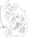
Figure 1 shows a flexible bag according to one embodiment of the present invention.
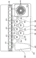
Fig. 2 is an exploded perspective view of an instrument for use with the bag of fig. 1 (including the bag of fig. 1) of an exemplary embodiment of the invention.
Fig. 3 shows a partial cross-sectional view of the apparatus of fig. 2, including the balloon assembly of fig. 2, with the bag of fig. 1 shown in phantom, according to an exemplary embodiment of the invention.
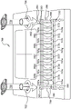
Figure 4 shows a motor used in one illustrative embodiment of the instrument of figure 2.
Fig. 5 shows a loading station (including the bag of fig. 1) for loading the bag of fig. 1 in accordance with an exemplary embodiment of the present invention.
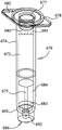
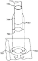
Fig. 6 shows a sample vial for loading a sample into the bag of fig. 1.
Fig. 7 shows a hydration vial for providing hydration fluid to the bag of fig. 1 in accordance with an exemplary embodiment of the present invention.
Fig. 8 shows a similar view to fig. 5 but presenting a different loading station configuration and loading station for vials used with the loading station, according to an exemplary embodiment of the present invention.
Fig. 9 shows a portion of the sample vial of fig. 8 and how the sample vial locks into the sample vial seat of the loading station of fig. 8 in an exemplary embodiment of the invention.
Fig. 10 shows a portion of the hydration vial of fig. 8 and how the hydration vial locks into the hydration vial seat of the loading station of fig. 8 according to an exemplary embodiment of the present invention.
Detailed description of the invention
Exemplary embodiments are described below with reference to the accompanying drawings. Many different forms and embodiments are possible without departing from the spirit and teachings of the present disclosure, and therefore the present disclosure should not be construed as limited to the exemplary embodiments set forth herein. Rather, these exemplary embodiments are provided so that this disclosure will be thorough and complete, and will convey the scope of the disclosure to those skilled in the art. In the drawings, the size and relative sizes of layers and regions may be exaggerated for clarity. Like reference numerals refer to like elements throughout the description.
Unless otherwise defined, all terms (including technical and scientific terms) used herein have the same meaning as commonly understood by one of ordinary skill in the art to which this disclosure belongs. It will be further understood that terms, such as those defined in commonly used dictionaries, should be interpreted as having a meaning that is consistent with their meaning in the context of this application and the relevant art and will not be interpreted in an idealized or overly formal sense unless expressly so defined herein. The terminology used in the description of the invention herein is for the purpose of describing particular embodiments only and is not intended to be limiting of the invention. Although some methods and materials similar or equivalent to those described herein can be used in the practice of the present disclosure, only certain exemplary materials and methods are described herein.
All publications, patent applications, patents, or other references mentioned herein are incorporated by reference in their entirety. In case of conflict in terminology, the present specification will control.
Various aspects of the disclosure, including apparatus, systems, methods, etc., may be described with reference to one or more exemplary embodiments. The terms "exemplary" and "illustrative" as used herein mean "serving as an example, instance, or illustration," and are not necessarily to be construed as preferred or advantageous over other embodiments disclosed herein. Furthermore, references to "an embodiment" or "an embodiment" of the present disclosure or invention include specific references to one or more embodiments thereof and vice versa and are intended to provide illustrative examples without limiting the scope of the invention, which is indicated by the appended claims rather than by the following description.
It should be noted that, as used in this specification and the appended claims, the singular forms "a," "an," and "the" include plural referents unless the content clearly dictates otherwise. Thus, for example, reference to "a tile" includes one, two or more tiles. Similarly, reference to multiple indicators should be construed as including a single indicator and/or multiple indicators unless the content and/or context clearly dictates otherwise. Thus, reference to a "tile" does not necessarily require a plurality of such tiles. Rather, it should be appreciated that one or more tiles are contemplated herein, independent of the combination.
The words "may" and "may" are used throughout this application in a permissive sense (i.e., meaning having the potential to), rather than the mandatory sense (i.e., meaning must). Furthermore, the terms "comprising," "having," "involving," "containing," "characterized by," variants thereof (e.g., "comprises," "having," "involves," "contains," etc.) and similar terms used herein, including the claims, are intended to be inclusive and/or open-ended, have the same meaning as the word "comprising" and variations thereof (e.g., "comprises" and "comprising"), and illustratively do not exclude additional, unrecited elements or method steps.
Directions and/or any terms used herein, such as "top," "bottom," "left," "right," "upper," "lower," "inner," "outer," "proximal," "distal," "forward," "reverse," etc., may be used solely to indicate relative directions and/or orientations, and may not otherwise limit the scope of the present disclosure, including the description, inventions, and/or claims.
It will be understood that when an element is referred to as being "coupled," "connected," or "responsive" or "on" another element, it can be directly coupled, connected, or responsive or on the other element or intervening elements may also be present. In contrast, when an element is referred to as being "directly coupled," "directly connected," or "directly responsive" or "directly on" another element, there are no intervening elements present.
Exemplary embodiments of the inventive concept are described herein with reference to cross-sectional illustrations that are schematic illustrations of idealized embodiments (and intermediate structures) of the exemplary embodiments. Variations from the shapes of the illustrations as a result, for example, of manufacturing techniques and/or tolerances, are to be expected. Thus, exemplary embodiments of the inventive concept should not be construed as limited to the particular shapes of regions illustrated herein but are to include deviations in shapes that result, for example, from manufacturing. Thus, the regions illustrated in the figures are schematic in nature and their shapes are not intended to illustrate the actual shape of a region of a device and are not intended to limit the scope of the exemplary embodiments.
It will be understood that, although the terms first, second, etc. may be used herein to describe various elements, these elements should not be limited by these terms. These terms are only used to distinguish one element from another. Thus, a "first" element may be termed a "second" element without departing from the teachings of the present embodiments.
It should also be understood that various embodiments described herein may be used in combination with any other embodiment described or disclosed without departing from the scope of the present disclosure. Thus, the products, components, elements, devices, apparatus, systems, methods, processes, compositions, and/or kits of certain embodiments of the present disclosure may include, incorporate, or otherwise contain the attributes, features, components, elements, steps, etc. (including systems, methods, apparatus, etc.) described in other embodiments disclosed herein without departing from the scope of the present disclosure. Thus, references to specific features associated with one embodiment should not be construed as limited to application within that embodiment.
The headings used herein are for organizational purposes only and are not meant to be used to limit the scope of the description or the claims. To facilitate understanding, identical reference numerals have been used, where possible, to designate identical elements that are common to the figures. Further, where possible, the same element numbers have been used in the various figures. Further, alternative configurations of particular elements may each include a separate letter appended to the element number.
The term "about" is used herein to mean approximately, within the stated area, approximately, or about. When the term "about" is used in conjunction with a numerical range, it modifies that range by extending the boundaries above and below the numerical values set forth. Generally, the term "about" is used herein to modify numerical values above and below the stated value by a variance of 5%. When such a range is expressed, another embodiment includes from the one particular value and/or to the other particular value. Similarly, when values are expressed as approximations, by use of the antecedent "about," it will be understood that the particular value forms another embodiment. It will be further understood that the endpoints of each of the ranges are significant both to the other endpoint, and independently of the other endpoint.
The word "or" as used herein means any one member of a particular list and also includes any combination of members of that list.
By "sample" is meant an animal, a tissue or organ from an animal, a cell (within a subject, taken directly from a subject, or maintained in culture or from a cultured cell line), a cell lysate (or lysate fraction) or a cell extract; a solution containing one or more molecules (e.g., polypeptides or nucleic acids) derived from cells, cellular material, or viral material; or a solution containing non-naturally occurring nucleic acids, which is assayed as described herein. The sample can also be any bodily fluid or excretion (such as, but not limited to, blood, urine, feces, saliva, tears, bile or cerebrospinal fluid) that may or may not contain host or pathogen cells, cellular components or nucleic acids.
The phrase "nucleic acid" as used herein refers to naturally occurring or synthetic oligonucleotides or polynucleotides, whether DNA or RNA or DNA-RNA hybrids, single-stranded or double-stranded, sense or antisense, capable of hybridizing to complementary nucleic acids by Watson-Crick base pairing. Nucleic acids of the invention can also include nucleotide analogs (e.g., BrdU) and non-phosphodiester internucleoside linkages (e.g., Peptide Nucleic Acids (PNAs) or thiodiester linkages). In particular, nucleic acids may include, but are not limited to, DNA, RNA, cDNA, gDNA, ssDNA, dsDNA, or any combination thereof.
By "probe", "primer" or "oligonucleotide" is meant a defined sequence of single-stranded nucleic acid molecules that can base pair with a second nucleic acid molecule containing a complementary sequence ("target"). The stability of the resulting hybrid depends on the length, GC content and the degree of base pairing that occurs. The degree of base pairing is influenced by parameters such as the degree of complementarity between the probe and the target molecule and the stringency of the hybridization conditions. Hybridization stringency is affected by parameters such as temperature, salt concentration, and the concentration of organic molecules such as formamide, and is determined by methods known to those skilled in the art. Probes, primers and oligonucleotides can be detectably labeled, either radioactively, fluorescently or non-radioactively, by methods well known to those skilled in the art. dsDNA binding dyes can be used to detect dsDNA. It will be understood that a "primer" is specifically configured to be extended by a polymerase, while a "probe" or "oligonucleotide" may or may not be so configured.
By "dsDNA binding dye" is meant a dye that typically fluoresces more strongly when bound to double stranded DNA with differential fluorescence over when bound to single stranded DNA or when free in solution. When referring to dsDNA binding dyes, it is to be understood that any suitable dye may be used herein, some non-limiting illustrative dyes are described in U.S. patent No. 7387887, which is incorporated herein by reference. Other signal generating substances may be used to detect nucleic acid amplification and melting, illustratively enzymes, antibodies, etc., as known in the art.
By "specifically hybridizes" is meant that the probe, primer, or oligonucleotide recognizes and physically interacts (i.e., base pairs) with substantially complementary nucleic acid (e.g., sample nucleic acid) under high stringency conditions, and does not substantially base pair with other nucleic acids.
By "high stringency conditions" is meant conditions that generally occur at about the melting temperature (Tm) -5 ℃ (i.e., 5 ° below the Tm of the probe). Functionally, high stringency conditions are used to identify nucleic acid sequences having at least 80% sequence identity.
Although PCR is the amplification method used in the examples herein, it should be understood that any amplification method using primers may be suitable. Such suitable procedures include Polymerase Chain Reaction (PCR), Strand Displacement Amplification (SDA), nucleic acid sequence-based amplification (NASBA), rolling circle amplification cascade (CRCA), loop-mediated isothermal amplification of DNA (LAMP), isothermal and chimeric primer-primed nucleic acid amplification (ICAN), target-based helicase-dependent amplification (HDA), transcription-mediated amplification (TMA), and the like. Thus, when the term PCR is used, it should be understood to include other alternative amplification methods. For amplification methods without discrete cycles, the reaction time may be used when measured at cycle or Cp, and additional reaction times may be added when additional PCR cycles are added in embodiments described herein. It should be understood that the scheme may need to be adjusted accordingly.
Although various examples herein refer to human targets and human pathogens, these examples are illustrative only. The methods, kits, and devices described herein can be used to detect and sequence a wide range of nucleic acid sequences from a wide variety of samples, including human, veterinary, industrial, and environmental samples.
Various embodiments disclosed herein use a self-contained nucleic acid analysis bag to illustratively determine the presence or absence of various biological substances, illustratively antigens and nucleic acid sequences, in a sample in a single closed system. Such systems, including bags and instruments for use with the bags, are disclosed in more detail in U.S. patent nos. 8394608 and 8895295 and U.S. patent application No. 2014-0283945, which are incorporated herein by reference. However, it should be understood that such bags are merely illustrative, and that the nucleic acid preparation and amplification reactions discussed herein may be performed using a variety of nucleic acid purification and amplification systems, as known in the art, in any of a variety of open or closed system sample containers known in the art, including 96-well plates, plates of other configurations, arrays, rotating disks, and the like. When the terms "sample well", "amplification vessel" and the like are used herein, these terms are meant to include wells, tubes and various other reaction vessels as used in these amplification systems. In one embodiment, the bag is used to assay for multiple pathogens. The pouch may illustratively include one or more blisters in the closed system that serve as sample wells. Illustratively, various steps including nucleic acid preparation, one large-volume multiplex PCR, one dilution of the amplified product and a second PCR, and finally, optional real-time detection or post amplification analysis such as melting-curve analysis, can be performed in the optionally disposable bag. Further, it should be understood that while various steps may be implemented in the bag of the present invention, one or more steps may be omitted for certain applications, and the bag configuration may be altered accordingly.
Fig. 1 shows an illustrative bag 510 that may be used in or reconfigured for various embodiments. The pouch 510 is similar to fig. 15 of U.S. patent No. 8895295, with like items numbered identically. Fitting 590 is provided with inlet channels 515a to 515l, which also serve as reagent reservoirs or waste reservoirs. Illustratively, the reagents may be freeze dried in fitting 590 and rehydrated prior to use. Blisters 522, 544, 546, 548, 564, and 566 with their respective channels 514, 538, 543, 552, 553, 562, and 565 are similar to the same numbered blisters of figure 15 of U.S. patent No. 8895295. Second stage reaction zone 580 of FIG. 1 is similar to U.S. patent application No. 8895295, except that second stage apertures 582 of high density array 581 are arranged in a slightly different pattern. The more circular pattern of high density array 581 of FIG. 1 eliminates holes in the corners and may result in more uniform filling of second stage holes 582. As shown, high density array 581 is provided with 102 second stage apertures 582. The bags 510 are suitable for FilmArray instruments (BioFire Diagnostics, LLC, Salt Lake City, UT). However, it should be understood that the bag embodiment is merely illustrative.
Although other containers may be used, bag 510 is illustratively formed from two layers of flexible plastic film or other flexible material such as polyester, polyethylene terephthalate (PET), polycarbonate, polypropylene, polymethyl methacrylate, and mixtures thereof, which may be prepared by any method known in the art, including extrusion, plasma deposition, and lamination. Metal foils or plastics with laminated aluminium may also be used. Other barrier materials are known in the art that can be sealed together to form the blister and channel. If plastic films are used, the layers may be bonded together, illustratively by heat sealing. Illustratively, the material has low nucleic acid binding capacity.
For embodiments employing fluorescence monitoring, plastic films are preferred that have sufficiently low absorbance and auto-fluoresce at the operating wavelength. Such materials can be identified by testing different plastics, different plasticizers and compounding ratios, and different thicknesses of the film. For plastics with aluminium or other laminated foils, the part of the bag to be read by the fluorescence detection device can be left without foil. For example, if fluorescence is detected in the second stage wells 582 of the second stage reaction zone 580 of the bag 510, one or both layers at the wells 582 will remain without foil. In the PCR example, a film laminate consisting of polyester (Mylar, Dupont, Wilmington DE) about 0.0048 inches (0.1219 mm) thick and polypropylene film 0.001-0.003 inches (0.025-0.076 mm) thick performed well. Illustratively, the bag 510 is made of a transparent material capable of transmitting approximately 80% -90% of incident light.
In an illustrative embodiment, the material is moved between the blisters by applying pressure, illustratively pneumatic pressure, across the blisters and the channel. Thus, in embodiments employing pressure, the bag material is illustratively sufficiently flexible to enable the pressure to have the desired effect. The term "flexible" is used herein to describe the physical characteristics of the pouch material. The term "flexible" is defined herein as readily deformable by the pressure levels used herein without cracking, breaking, crazing, etc. For example, thin plastic sheets such as SaranTMPackaging bag and Ziploc®Both the bag and the thin metal foil, such as aluminum foil, are flexible. However, even in embodiments employing pneumatic pressure, only certain regions of the blister and channel need be flexible. Further, only one side of the blister and channel need be flexible as long as the blister and channel can be easily deformed. Other areas of the bag 510 may be made of or reinforced with a rigid material.
Illustratively, plastic films are used for the bag 510. A sheet of metal (illustratively aluminum) or other suitable material may be ground or otherwise cut to produce a mold having a raised surface pattern. When mounted in a pneumatic press (illustratively a-5302-PDS, Janesville Tool inc., Milton WI), illustratively adjusted at an operating temperature of 195 ℃, the pneumatic press operates like a printer to melt the sealing surface of the plastic film only where the die contacts the film. As the pouch 510 is formed, various components, such as PCR primers (illustratively spotted onto the membrane and dried), antigen binding substrates, magnetic beads, and zirconium silicate beads, can be sealed within each blister. Reagents for sample processing may be co-located or separately located on the membrane prior to sealing. In one embodiment, Nucleoside Triphosphates (NTPs) are spotted onto the membrane separately from the polymerase and primers, substantially eliminating the activity of the polymerase until the reaction is hydrated by the aqueous sample. This allows for true hot start PCR and reduces or eliminates the need for expensive chemical hot start components if the aqueous sample has been heated prior to hydration.
The pouch 510 may be used in a similar manner as described in U.S. patent No. 8895295. In one illustrative embodiment, 300 μ l of a mixture comprising the sample to be tested (100 μ l) and lysis buffer (200 μ l) is injected into an injection port (not shown) in fitting 590 near inlet channel 515a and the sample mixture is aspirated into inlet channel 515 a. Water is also injected into a second injection port (not shown) of fitting 590 adjacent to inlet channel 5151 and is dispensed through a channel (not shown) provided in fitting 590, thereby hydrating up to 11 different reagents, each of which was previously provided in dry form at inlet channels 515 b-515 l. These reagents illustratively may include freeze-dried PCR reagents, DNA extraction reagents, wash solutions, immunoassay reagents, or other chemical entities. Illustratively, the reagents are used for nucleic acid extraction, first-stage multiplex PCR, dilution of multiplex reactions and preparation of second-stage PCR reagents, and control reactions. In the embodiment shown in fig. 1, all that needs to be injected is the sample solution of one injection port and the water of the other injection port. After injection, both injection ports may be sealed. For more information on various configurations of bag 510 and fitment 590, see U.S. patent No. 8895295, which has been incorporated by reference.
After injection, the sample moves from injection channel 515a to lysis blister 522 via channel 514. The cracking blisters 522 are provided with beads or particles 534, such as ceramic beads, and are configured for swirling upon impact using rotating blades or blades provided within a FilmArray @. Bead milling by shaking or vortexing the sample in the presence of lysis particles such as Zirconium Silicate (ZS) beads 534 is an effective method of forming the lysate. It is to be understood that terms such as "lyse," "lysis," and "lysate" as used herein are not limited to rupturing cells, and that such terms include the destruction of non-cellular particles such as viruses.
Fig. 4 shows a bead beating motor 819 that includes a blade 821 mountable on a first side 811 of a support member 802 of the instrument 800 shown in fig. 2. The blade may extend through the slot 804 to contact the bag 510. However, it should be understood that the motor 819 can be mounted to other structures of the instrument 800. In one illustrative embodiment, the Motor 819 is a Mabuchi RC-280SA-2865 DC Motor (Chiba, Japan) mounted on the support member 802. In one illustrative embodiment, the motor speed is 5000-. For the Mabuchi motor, it has been found that 7.2V provides sufficient rpm for the cleavage. It should be understood, however, that the actual speed may be somewhat slower when the blade 821 impacts the pocket 510. Other voltages and speeds may be used for lysis depending on the motor and paddle used. Optionally, a controlled small volume of air may be provided into the balloon 822 adjacent to the lysis blister 522. It has been found that, in some embodiments, partially filling the adjacent balloon with one or more small volumes of air helps to position and support the lysis blister during the lysis process. Alternatively, other structures, illustratively a rigid or compliant gasket or other retaining structure around lysis blister 522 may be used to restrain pouch 510 during lysis. It should also be understood that the motor 819 is illustrative only and that other devices may be used to grind, shake, or vortex a sample.
Once the cells have been sufficiently lysed, the sample moves through channel 538, blister 544 and channel 543 to blister 546, where the sample is mixed with nucleic acid binding substances such as silica coated magnetic beads 533. The mixture is allowed to incubate for an appropriate length of time, illustratively about 10 seconds to 10 minutes. A retractable magnet located within the instrument adjacent to the blister 546 captures the magnetic beads 533 from the solution, forming a pellet against the inner surface of the blister 546. The liquid is then moved out of blister 546 and back through blister 544 and into blister 522, blister 522 now serving as a waste container. One or more wash buffers from one or more of injection channels 515c-515e are provided to blister 546 via blister 544 and channel 543. Optionally, the magnet retracts and magnetic beads 533 are washed by moving the beads back and forth from blisters 544 and 546 through channel 543. Once the magnetic beads 533 are washed, the magnetic beads 533 are recaptured in the blister 546 by magnet activation, and the wash solution is then moved to the blister 522. This process can be repeated as necessary to wash the lysis buffer and sample debris from the nucleic acid-binding magnetic beads 533, illustratively including 3 or more washes, although one wash may be sufficient for some embodiments disclosed herein, and any number of washes is within the scope of the present disclosure.
After washing, the elution buffer stored at injection channel 515f moves to blister 548 and the magnet is withdrawn. The solution is circulated between blisters 546 and 548 via channel 552, breaking up the pellet of magnetic beads 533 in blister 546 and allowing the captured nucleic acids to dissociate from the beads and enter the solution. The magnet is again activated, capturing the magnetic beads 533 in the blister 546 and moving the eluted nucleic acid solution into the blister 548.
The first stage PCR master mix from injection channel 515g mixes with the nucleic acid sample in blister 548. Optionally, the mixture is mixed by forcing the mixture through passage 553 between 548 and 564. After several mixing cycles, the solution is contained in a blister 564, where a first-stage PCR primer deposit is provided, at least one set of primers per target, and a first-stage multiplex PCR is performed. If an RNA target is present, an RT step may be performed prior to or simultaneously with the first-stage multiplex PCR. The multiple PCR temperature cycles in the first phase of the FilmArray instrument are illustratively carried out for 15-20 cycles, although other levels of amplification may be desired, depending on the needs of a particular application. The first stage PCR mastermix may be any of a variety of mastermixes, as is known in the art. In one illustrative example, the first stage PCR master mix may be any chemical composition disclosed in US2015/0118715, incorporated herein by reference, that requires a PCR protocol of 20 seconds or less for each cycle.
After the first stage PCR has been performed for the desired number of cycles, the sample can be diluted, illustratively by forcing most of the sample back into blister 548, leaving only a small amount of sample in blister 564, and adding the second stage PCR master mix from injection channel 515 i. Alternatively, the dilution buffer from 515i can be moved to the blister 566 and then mixed with the amplified sample in the blister 564 by moving the fluid back and forth between the blisters 564 and 566. If desired, the dilution can be repeated several times using dilution buffers from injection channels 515j and 515k, or injection channel 515k can be retained for sequencing or for other post-PCR analysis, and then the second stage PCR master mix from injection channel 515h can be added to some or all of the diluted amplified sample. It will be appreciated that the level of dilution may be adjusted by varying the number of dilution steps or by varying the percentage of sample discarded prior to mixing with the dilution buffer or second stage PCR master mix containing the components for amplification (illustratively the polymerase, dntps and a suitable buffer), although other components may be suitable, particularly for non-PCR amplification methods. If desired, this mixture of sample and second stage PCR master mix may be preheated in the blister 564 before moving to the second stage wells 582 for second stage amplification. This preheating may avoid the need for hot start components (antibodies, chemicals, or others) in the second stage PCR mixture.
The illustrative second stage PCR master mix is incomplete, lacks primer pairs, and each of the 102 second stage wells 582 is preloaded with a specific PCR primer pair. The second stage PCR master mix may be devoid of other reaction components, if desired, and these components may also be pre-loaded in the second stage wells 582. Each primer pair may be similar or identical to a first-stage PCR primer pair, or may be nested within a first-stage primer pair. The sample moves from the blister 564 to the second stage well 582 to complete the PCR reaction mixture. Once high density array 581 is filled, the individual second stage reactions are sealed in their respective second stage blisters by any number of means, as is known in the art. An illustrative way of filling and sealing high density array 581 without cross contamination has been discussed in incorporated by reference U.S. patent No. 8895295. Illustratively, the various reactions in wells 582 of high density array 581 are thermally cycled simultaneously, illustratively with one or more Peltier devices, although other means for thermal cycling are known in the art.
In certain embodiments, the second stage PCR master mix contained the dsDNA binding dye LCGreen ® Plus (BioFire Diagnostics, LLC) to generate a signal indicative of amplification. However, it should be understood that this dye is merely illustrative and that other signals may be used, including other dsDNA binding dyes and probes that are fluorescently labeled, radiolabeled, chemiluminescent labeled, enzymatically labeled, etc., as known in the art. Alternatively, holes 582 of array 581 may have no signal provided and the results reported by subsequent processing.
When pneumatic pressure is used to move the material within the bag 510, in one embodiment an "air bladder" may be employed. The bladder assembly 810, a portion of which is shown in FIGS. 2-3, includes a bladder plate 824 housing a plurality of inflatable bladders 822, 844, 846, 848, 864, and 866, each of which is individually inflatable, illustratively by a source of pressurized gas. Because the airbag module 810 may be subjected to compressed gas and used multiple times, the airbag module 810 may be made of a tougher or thicker material than the bag. Alternatively, bladders 822, 844, 846, 848, 864, and 866 may be formed from a series of plates secured together with gaskets, seals, valves, and pistons. Other arrangements are also within the scope of the invention.
The success of the secondary PCR reaction depends on the template generated by the multiplex first-stage reaction. Generally, PCR is performed using high purity DNA. Methods such as phenol extraction or commercially available DNA extraction kits provide high purity DNA. Samples processed through bag 510 may need to be adjusted to compensate for the less pure preparation. PCR may be inhibited by components of the biological sample, which is a potential obstacle. Illustratively, hot start PCR, higher concentrations of taq polymerase, MgCl 2Adjustment of concentration, concentration of primerAdjustment and addition of adjuvants (such as DMSO, TMSO, or glycerol) optionally can be used to compensate for lower nucleic acid purity. Although purity issues are more likely to be issues with the first stage amplification, it should be understood that similar adjustments may also be provided in the second stage amplification.
When the bag 510 is placed within the instrument 800, the bladder assembly 810 is pressed against one face of the bag 510 such that if a particular bladder is inflated, the pressure will force liquid out of the corresponding blister in the bag 510. In addition to the air cells corresponding to the numerous blisters of bag 510, air cell assembly 810 may also have additional pneumatic actuators, such as air cells or pneumatically driven pistons, corresponding to the various channels of bag 510. Fig. 2-3 show illustrative piston or hard seals 838, 843, 852, 853, and 865 corresponding to channels 538, 543, 553, and 565 of pouch 510 and seals 871, 872, 873, 874 that minimize backflow to fitting 590. When activated, the hard seals 838, 843, 852, 853, and 865 form pinch valves to pinch off and close the respective passages. To confine liquid within a particular blister of the bag 510, a hard seal is activated on the passage leading to and from the blister, so that the actuator acts as a pinch valve to pinch off the passage. Illustratively, to mix two volumes of liquid in different blisters, a pinch valve actuator that seals the connecting channel is activated and a pneumatic bladder above the blisters is alternately pressurized, forcing the liquid back and forth through the channel connecting the blisters to mix the liquid therein. Pinch valve actuators can have various shapes and sizes, and can be configured to pinch off more than one channel at a time. Although pneumatic actuators are discussed herein, it should be understood that other ways of providing pressure to the bag are contemplated, including various electromechanical actuators, such as linear stepper motors, motor driven cams, rigid paddles driven by pneumatic, hydraulic, or electromagnetic forces, rollers, rocker arms, and in some cases, coiled springs (cocking springs). In addition, there are various methods of closing the channel, either reversibly or irreversibly, in addition to applying pressure perpendicular to the channel axis. These include wrapping the bag over the channel, heat sealing, rolling actuators, and various physical valves such as butterfly and ball valves sealed in the channel. Additionally, a small peltier device or other temperature regulator may be placed adjacent the channel and at a temperature sufficient to freeze the fluid, effectively forming a seal. Moreover, while the design of fig. 1 is applicable to automated instruments featuring actuator elements located on each blister and channel, it is also contemplated that the actuators may remain stationary and the bag 510 may be switched in one or two dimensions such that a few actuators may be used for several processing stations, including sample destruction, nucleic acid capture, first and second stage PCR, and other applications of the bag 510, such as immunoassays and immuno-PCR. The rollers acting on the tunnel and the blisters may prove particularly useful in configurations in which the bags 510 translate between stations. Thus, while a pneumatic actuator is used in the presently disclosed embodiments, when the term "pneumatic actuator" is used herein, it should be understood that other actuators and other ways of providing pressure may be used, depending on the configuration of the bag and the instrument.
Other prior art instruments teach PCR in sealed flexible containers. See, for example, U.S. patent nos. 6645758 and 6780617 and U.S. patent application No. 2014/0038272, which are incorporated herein by reference. However, inclusion of cell lysis in a sealed PCR vessel may improve ease of use and safety, particularly if the sample to be tested may contain biohazards. In the embodiments illustrated herein, waste from cell lysis and from all other steps remains within the sealed bag. However, it should be understood that the bag contents can be removed for further testing.
Fig. 2 shows an illustrative instrument 800 that may be used with bag 510. The instrument 800 includes a support member 802 that may form a wall of the housing or be mounted within the housing. The instrument 800 may further include a second support member (not shown) that is optionally movable relative to the support member 802 to enable insertion and extraction of the bag 510. Illustratively, a cover may cover the bag 510 once the bag 510 has been inserted into the instrument 800. In another embodiment, the two support members may be fixed, with the bag 510 being fixed in place by other mechanical means or by pneumatic pressure.
In the illustrated example, heaters 886 and 888 are mounted on a support member 802. However, it should be understood that this arrangement is merely illustrative and that other arrangements are possible. The airbag plate 810 with the airbags 822, 844, 846, 848, 864, 866, hard seals 838, 843, 852, 853, seals 871, 872, 873, 874 that will form the airbag module 808 can illustratively be mounted on a movable support structure that can be moved toward the bag 510 such that the pneumatic actuator is placed in contact with the bag 510. When bag 510 is inserted into instrument 800 and the movable support member is moved toward support member 802, each blister of bag 510 is in position adjacent each bladder of bladder assembly 810 and each seal of assembly 808 such that activation of the pneumatic actuator can force liquid from one or more blisters of bag 510 or can form a pinch valve for one or more channels of bag 510. The relationship between the blisters and channels of bag 510 and the bladders and seals of assembly 808 is illustrated in more detail in fig. 3.
Each pneumatic actuator is connected to a source of compressed air 895 via a valve 899. Although only a few hoses 878 are shown in FIG. 2, it should be understood that each pneumatic fitting is connected to a source 895 of pressurized gas via hose 878. The compressed gas source 895 may be a compressor, or the compressed gas source 895 may be a compressed gas cylinder, such as a carbon dioxide cylinder. Compressed gas cylinders are particularly useful if portability is desired. Other sources of compressed gas are within the scope of the invention.
The assembly 808 is illustratively mounted on a movable support member, but it should be understood that other configurations are possible.
Several other components of the instrument 810 are also connected to a source 895 of pressurized gas. The magnets 850 mounted on the second side 814 of the support member 802 are illustratively deployed and retracted via a hose 878 using gas from a compressed gas source 895, although other methods of moving the magnets 850 are known in the art. The magnet 850 is located in the recess 851 of the support member 802. It should be understood that the groove 851 may be a passage through the support member 802 such that the magnet 850 may contact the blister 546 of the pocket 510. However, depending on the material of the support member 802, it will be appreciated that the grooves 851 need not extend all the way through the support member 802, so long as the magnet 850 is close enough to provide a sufficient magnetic field at the blister 546 when the magnet 850 is deployed, and the magnet 850 does not significantly affect any magnetic beads 533 present in the blister 546 when the magnet 850 is retracted. When referring to retracting the magnet 850, it should be understood that an electromagnet may be used, and that the electromagnet may be activated and deactivated by controlling the current through the electromagnet. Thus, while the present description discusses withdrawing or retracting a magnet, it should be understood that these terms are broad enough to incorporate other ways of withdrawing a magnetic field. It should be appreciated that the pneumatic connection may be a pneumatic hose or a pneumatic air manifold, thus reducing the number of hoses or valves required.
Each pneumatic piston 868 of the pneumatic piston array 869 is also connected to a source 895 of pressurized gas via a hose 878. Although only two hoses 878 are shown connecting the pneumatic pistons 868 to the source of pressurized gas 895, it should be understood that each pneumatic piston 868 is connected to the source of pressurized gas 895. There are shown 12 pneumatic pistons 868.
A pair of heating/cooling devices, illustratively peltier heaters, are mounted to a second side 814 of support 802. The first stage heater 886 is positioned to heat and cool the contents of the blister 564 used for the first stage PCR. A second stage heater 888 is positioned to heat and cool the contents of the second stage bubble cap 582 of the bag 510 for the second stage PCR. However, it should be understood that these heaters may be used for other heating purposes as well, and may include other heaters as appropriate for a particular application.
When fluorescence detection is desired, an optical array 890 may be provided. As shown in fig. 2, optical array 890 includes a light source 898, illustratively a filtered LED light source, filtered white light or laser illumination, and a camera 896. The camera 896 illustratively has a plurality of photodetectors, each photodetector corresponding to a second stage aperture 582 in the bag 510. Alternatively, the camera 896 may capture an image containing all of the second stage apertures 582, and the image may be divided into separate regions corresponding to each of the second stage apertures 582. Depending on the configuration, the optical array 890 may be stationary or the optical array 890 may be placed on a mover attached to one or more motors and moved to obtain signals from each individual second stage aperture 582. It should be understood that other arrangements are possible.
As shown, the computer 894 controls the valve 899 of the compressed air source 895, and thus controls all of the pneumatics of the instrument 800. Computer 894 also controls heaters 886 and 888 and optical array 890. Each of these components is electrically connected, illustratively via a cable 891, but other physical or wireless connections are within the scope of the invention. It should be understood that the computer 894 may be located within the instrument 800 or may be external to the instrument 800. Further, the computer 894 may include a built-in circuit board that controls some or all of the components, and may also include an external computer, such as a desktop or laptop PC, to receive and display data from the optical array. An interface, illustratively a keyboard interface, may be provided that includes keys for entering information and variables such as temperature, cycle time, and the like. Illustratively, a display 892 is also provided. For example, the display 892 may be, for example, an LED, an LCD, or other such display.
Examples
Example 1: high density PCR
In one example, a standard commercially available immunofluorescence assay known for common respiratory viruses can detect the following 7 viruses: adenovirus, PIV1, PIV2, PIV3, RSV, influenza a virus and influenza b virus. Illustratively, a more complete set would include assays for other viruses including: coronavirus, human metapneumovirus, rhinovirus and non-HRV enterovirus. For highly variable viruses such as adenovirus or HRV, it is desirable to use multiple primers to target all branches of the viral lineage (illustratively 4 outer primer sets and 4 inner primer sets, respectively). For other viruses such as coronaviruses, there are 4 different lineages (229E, NL63, OC43, HKU1) which are not season-to-season specific, but are sufficiently divergent to require separate primer sets. FilmArray Respirancy Panel (BioFire Diagnostics, LLC, Salt Lake City, UT) includes adenovirus, coronavirus HKU1, coronavirus NL63, coronavirus 229E, coronavirus OC43, human metapneumovirus, human rhinovirus/enterovirus, influenza A virus/H1, influenza A virus/H3, influenza A virus/H1-2009, influenza B virus, parainfluenza virus type 1, parainfluenza virus type 2, parainfluenza virus type 2, and UT Influenza virus type 3, parainfluenza virus type 4 and respiratory syncytial virus. In addition to these viruses, FilmArray Respirancy Panel comprised the following 3 species of bacteria: bordetella pertussis: (B.pertussis)Bordetella pertussis) Chlamydophila pneumoniae: (Chlamydophila pneumoniae) And Mycoplasma pneumoniae: (Mycoplasma pneumonia). High density array 581 can contain such sets in a single pocket 510. Other groups were available for FilmArray ®, with at least 20 pathogens tested per group.
Example 2: bag loading
Fig. 5 shows a loading station 600. As shown, bag 510 of fig. 1 has been loaded into slot 610 of loading station 600 such that only fitment 590 of bag 510 is visible. As shown, the loading station 600 is provided with a sample vial seat 602 for receiving a sample vial 650 and a hydration vial seat 604 for receiving a hydration vial 670. However, it should be understood that the seat and vial are used to assist in the workflow and are merely illustrative. Other configurations and use with other bags and other devices are also within the scope of the present disclosure.
The sample is pipetted or otherwise loaded into the sample vial 650. As discussed in more detail below, depending on the workflow, the sample vial 650 may already contain a buffer or other fluid 652 for receiving the biological sample, or the operator may add the biological sample in an appropriate buffer to the sample vial 650. Optionally, the buffer may be provided in a separate ampoule and the appropriate amount of buffer dispensed. Similarly, the hydration vial 670 may be pre-loaded with water, buffer, or other fluid 672, or an operator may load the hydration vial 670 with such fluid.
The illustrative fitting 590 includes an injection port 541 illustratively formed near a second surface 595 of the fitting 590. As shown, injection port 541 is located in a sample injection opening 563, which injection opening 563 is configured to receive a cannula transfer container, such as a cannula syringe, through a first surface 594 of fitting 590. In this illustrative configuration, the injection port 541 is protected from accidental puncture and will not open until the cannula transport container is placed in the sample injection opening 563. Similarly, illustrative fitting 590 includes a second injection port 588 illustratively formed near a second surface 595 of fitting 590, and is located in a hydrating fluid injection opening 583, which injection opening 583 is configured similar to sample injection opening 563. As configured in this illustrative embodiment, the injection port 541 is for receiving a sample of the sample to be tested that is to be moved to the chamber 592a or directly into the lysis blister 522 (fig. 1), and the second injection port 588 is configured for receiving a hydrating fluid 672 (shown in fig. 7), such as water or a buffer, which hydrating fluid 672 is moved to the chambers 592b through 592l for subsequent movement through the inlet channels 515b through 515 l. It is understood that the arrangement of the injection ports 541 and 588 and the openings 563 and 583 are illustrative and that other configurations are within the scope of the present disclosure.
As best shown in fig. 6, the illustrative sample vial 650 includes a top surface 662, a body 654, and a cannula 655, arranged similarly to many cannula-type syringes. In this illustrative embodiment, instead of a plunger as found in many cannula syringes, the sample vial 650 is provided with a cap 658 for extending through the top surface 662 to seal the vial body 654. Illustratively, the operator will pour, pipette, insert a swab, scoop out a solid or semi-solid material, or otherwise transfer a fluid and/or other material through the opening 657 in the top surface 662 and into the vial 654.
Depending on the type of sample to be tested, the sample vial 650 may be provided with a filter 646, the filter 646 illustratively being located at or near the hexagonal bottom surface 666 of the vial body 654. As shown, the filter 646 is held in place by an O-ring 644. However, it should be understood that the filter 646 may be secured in place by adhesive, by welding, by press fitting in place, or by other means known in the art. When cannula 655 is inserted into sample injection opening 653 and a sample is drawn into bag 510, the sample material is filtered as it is drawn through filter 646 and into cannula 655. Although the choice of Filter material depends on sample type and particle size, filters suitable for use with various biological samples include Pall 100 μm Absolute multiple Polypropylene Melt Blown Media and Millipore 80 μm Polypropylene Net Filter. Most syringe filters are designed to exclude organisms of a certain size, thereby removing these organisms from the filtrate. Unlike such pre-existing filters, these illustrative filters are selected based on their ability to exclude larger particles present in feces, soil, powder, etc., while allowing target organisms (e.g., bacteria, viruses, protozoa, and fungal organisms) having diameters of about 60 μm or less to pass through the filter. Moreover, the illustrative filter material is inert (i.e., does not bind organisms or nucleic acids) and is relatively resistant to clogging. It should be understood that these illustrative filters were selected for samples containing protozoa as the target organism (up to about 60 μm). Because some bag configurations may only test for smaller targets, filters with smaller pore sizes, such as 1-10 μm for bacteria and fungi, and less than 1 μm if only viral particles are detected, may be desirable. Of course, larger pore size filters can still be used to filter smaller targets. Such filters are particularly useful for sample types having large amounts of particulate matter, such as soil, feces, and powders that may clog fluid systems. Further, it should be understood that the pore size is selected based on the material to be filtered, and that other pore sizes are within the scope of the invention.
It should be appreciated that one or more dried components for sample preparation may be provided in the vial 654. Such additives may include buffers, stabilizers, proteases, dnases, dnase inhibitors, RNA, rnase inhibitors, lysozyme, reducing agents, and the like. Alternatively, such components may be included in the sample buffer or may be added downstream after the sample exits vial 650 for further processing. It will be appreciated that the choice of such additives will depend on the type of sample and the further processing desired. Additives that help reduce viscosity or help solubility to allow a sample to pass through filter 646 are particularly useful.
As shown, the bottom cap 664 is provided with a hexagonal portion 666, the hexagonal portion 666 being configured to fit into the hexagonal sample vial holder 602. Although in the illustrative embodiment hexagonal portion 666 and sample vial seat are hexagonal, it should be understood that other shapes may be used and that a hexagonal or other mating or interlocking shape may be provided to assist an operator in removing bottom cap 664. Alternatively, the operator can remove the bottom cap 664 by other means, such as using two hands to unscrew the bottom cap 664 from the bottle body 654. The bottom cap 654 may be press fit, fitted, or otherwise capped onto the bottle 654.
In the illustrated embodiment, the bottom cap 664 is provided with a base 648 such that the bottom end 659 of the insertion tube 655 extends into the base 648. Illustratively, the bottom end 659 of the insertion tube 655 fits tightly within the base 648 such that the base 648 provides an air-tight seal around the open bottom end 659 of the insertion tube 655. Optionally, a vent 649 is provided between the bottom cap 664 and the bottle 654.
Turning now to fig. 7, hydration vial 670 may be configured similarly to sample vial 650. However, it may be desirable to pre-load the hydration vial 670 with the hydration fluid 672 and pre-seal the hydration fluid 672 in the hydration vial 670, as shown in fig. 7. As shown in fig. 7, the illustrative hydration vial 670 includes a top surface 682, a body 674, and a cannula 675, which are arranged similarly to the sample vial 650. However, the tongues 680 of the cap 678 of the illustrative hydration vial 670 have been press fit into the opening 677 of the top surface 682, and the cap 678 may be sealed to the top surface 682, thereby preventing the hydration vial 670 from opening. This arrangement is merely illustrative, and it should be understood that other ways of sealing the hydration fluid 672 within the hydration vial 670 are contemplated herein. Illustratively, the vial body 674 and the cannula 675 may be provided completely full or substantially completely full of fluid such that handling or rotating the hydration vial 670 will not allow air to enter the cannula 675. Alternatively, some air 685 or other gas may be present within the vial body 674 and the operator may hold the hydrated body in an upright position to prevent air from entering the cannula 675. In yet another alternative embodiment, air 685 may be provided under pressure, and removal of bottom cap 684 will cause hydration fluid to be forced through cannula 675. As shown, the hydration vial 670 is not provided with a filter, but one may be provided as desired.
A bottom cap 684 may be provided to retain any fluid that may drip from the cannula 675 and to prevent contamination of the hydration fluid 672 in the cannula 675. A wiper 683 may be provided in the bottom cap 684 to wipe excess fluid from the bottom of the cannula 675. The conical shape of wiper 683 can also help retain the droplets in bottom cap 684 during subsequent handling and disposal. In the illustrative embodiment, the bottom cap 684 is provided with a hexagonal portion 686 for mating with the hexagonal hydration vial socket 604, although other shapes are possible with the sample vial 650, as discussed above. The hexagonal portion 686 and the hexagonal hydration vial seat 604 of the hydration vial 670 may have different sizes and/or different shapes than the hexagonal portion 666 and the hexagonal sample vial seat 602 of the sample vial 650 so that only the sample vial 650 is easily loaded into the sample vial seat 602 and only the hydration vial 670 is easily loaded into the hydration vial seat 604 to reduce the chance of the operator confusing the sample vial 650 with the hydration vial 670 so that the correct fluid is injected through the ports 541 and 588. Additionally, sample vial 650 and injection opening 563 may be partially or completely provided in matching specific colors (illustratively red), while hydration vial 670 and injection opening 583 may be partially or completely provided in different matching specific colors (illustratively blue) to provide visual assistance to the operator when the correct fluid is provided in ports 541 and 588. To further minimize the risk of inserting the wrong liquid into the wrong injection opening, the diameter of cannula 655 may be different than the diameter of cannula 675, and the diameters of sample injection opening 563 and hydration fluid injection opening 583 may be similarly different. Other configurations are within the scope of the present disclosure.
Returning to fig. 5, illustratively, to load the bag 510, the operator places a sample vial 650 in the sample vial seat 602 and a hydration vial 670 in the hydration vial seat 604 on the loading station 600. The bag 510 is also placed in the slot 610. The sample is placed in sample buffer 652 in any manner suitable for the type of sample, including inserting a swab 630, pipetting the fluid sample, dropping blood directly from the patient into the vial, and placing a solid or semi-solid sample, such as stool, in the vial with optional vortexing or other mixing, as is standard in the art. Depending on the sample type and desired target nucleic acid, the sample buffer may contain one or more additives or stabilizers illustratively used to treat biological or environmental samples such as proteases, dnases, dnase inhibitors, rnases, rnase inhibitors, lysozyme, and the like. Additionally or alternatively, these additives may be provided in the bag 510. Preferably, prior to vortexing or mixing, the operator closes the sample vial 650 by placing the tongue 660 of the cap 658 through the opening 657. The insertion of the tongue 660 pressurizes the air contained within the bottle 654. Illustratively, the volume of the tongue 660 is equal to or greater than the volume of the cannula 655. Illustratively, when the bottom cap 664 is removed, the hermetic seal between the base 648 and the bottom end 659 of the cannula 655 is broken and substantially all air is forced out of the cannula 655. If the volume of the tongue 660 is greater than the volume of the cannula 655, this will help ensure that a maximum amount of air is expelled from the cannula 655. Any overflow in the amount of fluid forced into and possibly through the cannula 655 may be captured in the bottom cap 664 and removed from the bottom of the cannula 655 by the wiper 663. By completely or substantially completely filling cannula 655, the amount of air bubbles in bag 510 when the bag is loaded is minimized. The one or more vents 649 may facilitate separation of the bottom cap 664 from the hydration vial 650.
Because bottom cap 664 is provided with a hexagonal portion 666, the hexagonal portion 666 being configured to fit into hexagonal sample vial holder 602, an operator can easily unscrew bottom cap 654 while the bottom cap engages holder 602, thereby exposing cannula 655. The cannula 655 is then inserted into the sample injection opening 563 and pushed in, opening the injection port 541. With or without pressure from the vial body, the vacuum within bag 590 (or the reduced pressure within the bag relative to atmospheric pressure or the pressure outside the bag), illustratively forcing the sample through a filter (if present), can be used to draw the sample into bag 510, illustratively into chamber 592a in fitting 590, for subsequent movement into lysis chamber 522. By ensuring that the cannula 655 is substantially filled with fluid 652, the amount of air or other gas that moves from the sample vial 650 into the pouch 510 is minimized, thereby minimizing the size and number of bubbles. Further, when a prior art syringe having a plunger is used and the vacuum within bag 590 draws fluid, the plunger pulls down on the syringe, thereby equalizing the pressure within the syringe. In the embodiment of fig. 5-6, because the opening at the top of each vial body is sealed, as fluid is drawn from the vial from the vacuum within the pocket 590, the vial will also experience a negative pressure and may degas the sample and draw some remaining air bubbles from the pocket 590. Cannula 655 is then withdrawn from sample injection opening 563 and sample vial 650 and bottom cap 664 are disposed according to the protocol. With the vial body 654 under negative pressure, air bubbles that may have collected near the injection port 541 can be drawn out of the bag 510 as the cannula 655 is withdrawn, further reducing the air bubbles in the bag.
Similarly, the operator unscrews the bottom cap 684 from the hydration vial 670, thereby exposing the cannula 675. If the contents of the hydration vial 670 are provided under pressure, a small amount of hydration fluid may leak into the bottom cap 684 when the cannula 675 is separated from the base 692. The one or more vents 693 may facilitate separation of the bottom cap 684 from the hydration vial 670. The cannula 675 is then inserted into the hydration injection opening 583 and pushed in, opening the injection port 588. The vacuum from within fitting 590 may be used to draw hydration fluid into bag 510, illustratively into chambers 592b-592l, for subsequent movement into each blister of bag 510. The cannula 675 is removed from the hydration infusion opening 583, the bag 510 is removed from the loading station 600 and placed in the instrument 800, and the run is started. It should be understood that the removal of the bottle is illustrative only. If the instrument and vial configuration permits, the vial can be permanently inserted into the injection port, thereby becoming part of the closed system of the bag and minimizing contamination from the sample. In such an embodiment, a seal may not be required.
In the illustrative embodiment of the sample vial 650 discussed above, the volume of the tongue 660 is equal to or greater than the volume of the cannula 655. In one exemplary embodiment where the bag 510 has a 1 ml fill volume, the vial 654 may be provided with 1.5 ml of sample fluid 652 and a 1 ml volume of air 645 above the sample fluid. Thus, the volume of the air is 40% of the bottle 654. However, it should be understood that other percentages of air may be used, including 10%, 20%, 30%, 50%, 60%, 70%, 80%, and amounts in between. When tongue 660 is inserted through opening 657, the air above the sample fluid is illustratively compressed by up to about 50%, but compressions in the range of 40-60%, 30-70%, 20-80%, and 10-90% are possible. It will be appreciated that the selection of the volumes of air and sample fluid depends on the sample size, cannula diameter, whether it is desired to remove the vial prior to running the fluid reaction, and some other factors. For example, a scooped or wiped sample may require a significantly larger volume of sample fluid regardless of the fill volume of the fluidic system.
The illustrative bottles 654 and 674 are cylindrical. However, because these illustrative vials do not provide a plunger, it should be understood that the vial body need not have a circular cross-section, and any body shape is within the scope of the present invention.
Fig. 8-10 show alternative embodiments of the loading station 600 and vials 650, 670, wherein like numerals indicate like parts. The loading station 700 as shown in fig. 8 may be similar to loading station 600, having a sample vial seat 702 and a hydration vial seat 704 and a slot 710 for receiving a bag 510, similar to those shown in fig. 1. However, according to at least one embodiment, the shape and location of the seats between the loading station 600 and the loading station 700 are significantly different. For example, in at least one embodiment, seats 702 and 704 are closer to bag 510 than seats 602, 604 of loading station 600. Because of this reduced distance, there is less chance of dripping when the bag 510 is loaded. Further, as best seen in fig. 9-10, the bottom cover 764 of the sample vial 750 is provided with 4 relatively short fins 767 that fit within the 4 mating grooves 703 of the sample vial holder 702, and the bottom cover 784 of the hydration vial 770 is provided with two relatively long fins 787 that fit within the two mating grooves 705 of the hydration vial holder 704. These fins replace the hexagonal portions 666 and 686 of the vials 650 and 670, respectively. The larger number of fins 767 on the bottom cover 764 prevents the sample vial 750 from being placed in the hydration vial holder 704, and the longer fins 787 of the bottom cover 784 prevents the hydration vial 770 from being placed in the sample vial holder 702. However, it should be understood that the use of different sizes and numbers of fins is illustrative only, and that different keying systems are within the scope of the present disclosure. As discussed above with respect to the loading station 600, the seats 702, 704 of the loading station 700 may be used to assist in unscrewing the bottom caps 764, 784 from their respective bottles 754, 774 to assist in the loading process.
Although sample vials 650, 750 and hydration vials 670, 770 are used in the illustrative examples for loading bag 510, it should be understood that these loading bottles are suitable for loading any of the bags disclosed herein. They are also suitable for loading other fluidic or microfluidic devices, particularly fluidic devices configured to draw liquids into the fluidic device using vacuum or suction.
Example 3: sample preparation
In this illustrative embodiment, samples from Lower Respiratory Tract Infections (LRTI) are used. However, it should be understood that the present method may be adapted to other sample types, including but not limited to biological and environmental sample types that are difficult to handle, and is particularly useful for any sample type that selectively binds to a collection material and then releases. LRTI is a common disease, but identification of causative agents can be difficult due to biased diagnostic techniques and inhibitory sample characteristics. The current "gold standard" for pathogen identification is bacterial culture, which is highly subjective, lacks sensitivity, and is an incomplete screening method because culture can only identify culturable pathogens, but non-culturable pathogens are not detected. LRTI samples include multiple sample types such as bronchoalveolar lavage (BAL), small BAL, bronchial lavage, sputum, and endotracheal suction (ETA), all of which have unique and often challenging characteristics. Sputum and ETA samples can be difficult to manipulate, can be slow to process, and can be highly inhibitory to molecular detection methods. In addition, LRTI pathogens include gram-positive and gram-negative bacterial, viral and fungal organisms, often requiring multiple sample processing methods.
Sputum is a semi-solid sample matrix with variable viscosity and particles. BAL may have a viscosity similar to clean saline or may have a viscosity similar to sputum, both of which may present disposal challenges. Difficulties include sample non-pipettability, volume inaccuracy of pipette due to viscosity change, air pockets, pullback, residue and foaming during bag injection or sample handling. Due to the high viscosity, it may be difficult to separate pathogens from the sample matrix. In addition, rnase activity present in such samples may affect RNA detection. For this sample type, a combination of physical and chemical lysis may be effective.
The sputum sample may be obtained using any suitable means, including expectorating the patient into a suitable collection container or inducing the patient to produce the sample. Most pathogen detection methods use a volume transfer system that may be difficult to use with sputum or other viscous samples. Typically, the sample is pre-treated to liquefy the sample for subsequent pipetting. In an illustrative embodiment, the swab is used to transfer a sample, reducing or eliminating the need for a pre-treatment step. While pipettes, other swabs, and other transfer devices may be used to transfer samples, the use of a flocked swab provides a simple and easy method of introducing samples into a testing system while minimizing sample handling problems. A suitable swab is a FLOQSwabs ™ shaft (Copan Diagnostics, Murrieta, CA). This illustrative flocked swab is hydrophilic and well suited for collecting pathogens. For such viscous samples or solid or semi-solid samples, illustratively having a viscosity of 3 cP or greater, the flocked swab may preferentially collect organisms over the solid material. The flocked swab may also preferentially release organisms relative to the sample matrix material. Other materials that preferentially collect and release organisms relative to the sample matrix may be used to transfer the sample, and it should be understood that the swab format is merely illustrative.
In an illustrative embodiment, the swab 630 may be placed in a sample collected from a patient, or may be placed in an environmental sample. The swab 630 may then be placed directly into the sample buffer 652 in the sample vial 650. Sample buffer 652 may be any buffer depending on the sample type. As shown in fig. 6, if desired, the tip of the swab 630 may be snapped off and the cap 658 may be used to close the vial 654. The presence of the swab tip 630 within the bottle body 654 should not significantly affect the use of the vial 650. The vial 650 may be shaken, illustratively by inverting 3 times, or illustratively more vigorously for 10 seconds to release any pathogens present from the swab 630. Alternatively, the swab 630 may be swirled in the sample buffer 652, and the swab 630 may then be removed from the vial 650. While not being bound by theory, it is believed that the flocked swab may preferentially collect cells, organisms and viruses relative to the sample matrix, and may then retain a portion of the sample matrix, such as a viscous sputum material, while releasing at least the organisms and viruses. However, it should be understood that other swabs or transfer devices may be used in various embodiments. Illustratively, the sample may be concentrated using any transfer material that selectively collects and releases the desired sample relative to the sample matrix. Such materials include swabs, brushes, sponges, filters, utensils, rings, papers, or other absorbent materials that selectively bind and release a desired sample and that can be placed in contact with the sample during sample transfer for analysis.
Thus, it has been found that such flocked swabs are suitable for collecting and releasing pathogens in viscous samples, such as LRTI samples, and that flocked swabs provide a fairly uniform collection volume. A single FLOQSwabs ™ swab collects approximately 150-300. mu.l of sample, including higher viscosity sample types such as sputum, in a fairly reproducible manner. It is within the scope of the present invention to repeatedly collect other materials having viscous samples in a small sample volume range (illustratively in the 2-fold to 4-fold volume range). It should be understood that the sample volume range is the volume range over which the sample collection material can be repeatedly collected, such that the illustrative 2-fold range is 150-. Illustrative examples include samples of sizes that can collect 50-150. mu.l and 300-. While such swabs may be used to collect a specimen from a patient, in one illustrative embodiment, a swab is used to collect a specimen in a repeatable manner and transfer the specimen from a suitable collection container to another container for further processing. However, it should be understood that other suitable collection and transfer materials may be used with the various embodiments disclosed herein, as are known in the art.
Pretreatment of difficult samples is known in the art for some time. For example, sputum can be treated with Dithiothreitol (DTT) and/or heated for 15 minutes or more, sometimes 30 minutes or more. A sample buffer 652 may be used which may partially or completely liquefy the sputum-like specimen, illustratively without such pretreatment. Buffers known in the art typically use detergents in an amount of 10% by volume or less. Illustrative sample buffer 652 of the present invention may contain 10% or more detergent, illustratively 12%, 15%, 18%, 20% or more detergent. Suitable detergents include nonionic, ionic and zwitterionic detergents which may be used. In an illustrative embodiment, a non-ionic detergent such as 15% Triton-X may be used. Other non-limiting detergents include Tween-20, SDS, and NP-40. It has been found that such higher concentrations of detergent can reduce or eliminate the need for pretreatment, such as heating the sample or DTT mixture pretreatment, prior to nucleic acid extraction. Thus, the sample may be processed with only 5 minutes or less, 2 minutes or less, 1 minute or less, or even no hold time. However, it should be understood that pretreatment may be desirable for some sample types. Sample buffer 652 may also contain a guanidinium compound, such as guanidinium hydrochloride. In one illustrative example, the buffer is acidic, illustratively having a pH of about 2 to about 6. In certain sample preparation methods, illustratively when the sample type is blood or a blood component, an alcohol such as isopropanol is used in sample buffer 652. However, other sample buffers may be alcohol-free. It has been found that in various illustrative embodiments employing detergents at concentrations of 10% or more, illustratively 15%, the alcohol may be omitted from sample buffer 652.
As discussed above, the sample vial 650 may be provided with a filter 646. When the cannula 655 is inserted into the sample injection opening 653 and a sample is drawn into the bag 510, the sample material is filtered as it is drawn through the filter 646 and into the cannula 655. Such a filter 646 may be clogged by a viscous sample such as sputum. In some embodiments, sample vial 650 may be provided with a protease, such as proteinase K, or the protease may be otherwise provided in sample vial 650 or may be added with sample buffer 652. If the protease is provided in a dry form, the introduction of the sample buffer 652 rehydrates the protease, and the introduction of the sample into the sample buffer 652 enables the protease to begin to break down the proteins in the sample even before the sample is transferred to the bag 510 and reaches the lysis blister 522. The action of the protease may help to reduce the viscosity of the sample, thereby improving the ability of the sample to pass through filter 646 or improving other downstream processing steps. Thus, more pathogens can be released from the sample with the protease present in the sample vial 650. However, in some embodiments using a protease, it may be desirable to add the protease directly to the sample buffer or later in the process, illustratively by drying the protease in inlet channel 515b, while in other embodiments, the protease may be omitted.
It is to be appreciated that preferential transfer of pathogens by using flocked swabs, higher detergent concentrations, filtration through filter 646 in the presence of proteases, or a combination thereof may obviate the need for heat or DTT pretreatment and may sufficiently break down such viscous samples. Such samples may then be prepared for subsequent lysis steps, followed by PCR or other testing.
Although the above illustrative description focuses on sputum and other LRTI sample types, it should be understood that the above methods and apparatus may be used with a wide variety of sample types, particularly (but not limited to) difficult sample types. In addition to sputum, BAL, and other LRTI sample types, other difficult biological samples include, but are not limited to, mucus, stool, tissue homogenates, ground tissue, paraffin-treated formalin-embedded tissue, bone homogenates, eschar, pus, synovial fluid, lymph node aspirates, and gastric lavage fluid. Environmental samples (illustratively soil, surfaces, powders, or food) can also present challenges. Transfer using a flocked swab or other transfer means that preferentially collects and releases pathogens allows for relatively consistent collection of pathogens, even from samples that are difficult to accurately pipette or measure. A sample buffer that partially or completely liquefies the sample matrix may be used. The sample is aspirated through the filter, illustratively in the presence of higher concentrations of detergents or additives to aid in sample preparation, to aid in breaking down the sample matrix to provide the sample in a form suitable for further processing.
Example 4: direct blood sample
In this embodiment, a direct blood sample is used for host RNA analysis. As used herein, "direct blood" means a blood sample that has not been cultured. Illustrative direct blood samples include whole blood directly from a host organism (illustratively a human), a whole blood component (e.g., plasma or serum), whole blood collected in an anticoagulant solution (e.g., EDTA, citrate), or whole blood collected in an RNA stabilization solution. It is understood that the host's response to infectious, acute, and/or chronic diseases results in changes in the production of certain RNA molecules, including but not limited to ribosomal RNA, messenger RNA (mrna), long noncoding RNA, or small interfering RNA. This change in RNA production can be used to indicate the source of the host disease. RNA in direct blood samples is typically purified using automated or manual extraction methods including centrifugation, washing, addition of optimized buffers, protein and nucleic acid digestion (often with additional washing), and elution. In many prior art methods, this is all done using equipment separate from the end point molecular diagnostic tool, and typically takes 90 minutes or more. The resulting purified sample is then manually added to an end-point molecular diagnostic system such as a cDNA microarray or qPCR instrument. The process of purifying host RNA samples typically requires a significant amount of time, external equipment, and sample handling, all of which can affect the integrity and quality of the sample. An alternative approach is to add a direct blood sample (illustratively in any of the forms defined above) directly to the sample buffer 652. Illustrative sample buffers contain chaotropic agents (chaotropic agents) that aid in nucleic acid binding and recovery while reducing proteins that degrade RNA, like RNAses. Illustratively, the ratio of direct blood sample to sample buffer is in the range of 1:8 to 1:1, more specifically in the range of 1:5 to 1:1.67, but it should be understood that other ratios are possible. The sample may then be loaded directly into the bag 510, as discussed above. As discussed above, host RNA is extracted and purified in a closed system, illustratively with minimal mixing or without any additional user manipulation in vial 650. Such sample preparation can be accomplished without any or all of the steps involved in centrifugation, ethanol precipitation, and DNA digestion. Thus, the sample can be processed in only 2 minutes or less and does not require external equipment from the end point molecular diagnostic tool.
One example of such an application is the detection of host RNA changes in response to influenza infection. A100 microliter (100. mu.L) whole blood sample collected in RNA stabilizing solution according to the manufacturer's instructions is added to sample buffer 652, illustratively sample buffer provided with a film array Respiratory Panel (BioFire Diagnostics, LLC). Illustratively, a sample volume of 300-900. mu.l or 2-5 times the sample buffer may be used. The mixture is then injected into the disposable bag 510. Sample extraction, purification, reverse transcription and two-stage polymerase chain reaction resulted in the measurement of significantly upregulated host RNA in response to viral infection relative to healthy controls. The entire process of sample purification and qPCR analysis required less than 70 minutes.
A further example of the present application is the detection of host RNA from whole blood collected in anticoagulant solution (EDTA). 100 microliters (100 μ L) of this whole blood sample was added to 800 μ L of the same sample buffer. The mixture is then injected into the bag 510. Sample extraction, purification, reverse transcription and two-stage polymerase chain reaction lead to the measurement of host RNA. The entire process of sample purification and qPCR analysis required less than 70 minutes.
These examples demonstrate that nucleic acids, illustratively high copy number nucleic acids, including but not limited to various RNA molecules, bacteria, viruses, or other microorganisms, can be extracted from direct blood samples using only lysis (illustratively chemical and/or mechanical lysis) and nucleic acid purification (illustratively by binding to a silica substrate and eluting, illustratively no more than 5 washes or no more than 3 washes, but as few as one wash is within the scope of the invention). These nucleic acids can be extracted and prepared without centrifugation or enzymatic digestion and without many repeated washing steps. As also demonstrated, these extracted nucleic acids are suitable as templates for subsequent amplification.
The present invention may be embodied in other specific forms without departing from its spirit or essential characteristics. The described embodiments are to be considered in all respects only as illustrative and not restrictive. The scope of the invention is, therefore, indicated by the appended claims rather than by the foregoing description. While certain embodiments and details have been included herein and in the following disclosure for the purpose of illustrating the invention, it will be apparent to those skilled in the art that various changes in the methods and apparatus disclosed herein may be made without departing from the scope of the invention, which is defined in the appended claims. All changes which come within the meaning and range of equivalency of the claims are to be embraced within their scope.
Claims (35)
1. A method of sample collection, the method comprising:
collecting a sample comprising biological or environmental material to provide a collected sample,
contacting the collected sample with a swab,
placing the swab with the collected sample in a sample buffer, thereby transferring at least a portion of the collected sample into the sample buffer to provide a sample buffer comprising the collected sample, and
the sample is filtered and the filtrate is then,
wherein there is no pretreatment step for more than 2 minutes,
wherein the collecting step lacks a swab collecting step,
wherein the collecting step comprises obtaining a sample from a bronchoalveolar lavage (BAL), a mini-BAL, a bronchial lavage, an endotracheal aspirate (ETA), or sputum to provide the collected sample, and
wherein the sample buffer comprises a detergent in an amount of at least 10% by volume of the sample buffer.
2. The method of collecting a sample of claim 1, further comprising contacting the sample in the sample buffer with a protease.
3. The method of collecting a sample of claim 1, wherein the swab is a flocked swab.
4. The specimen collection method of claim 1 wherein said collecting step comprises collecting said specimen from a specimen container without pipetting and said swab is configured to absorb and release an amount of specimen in the range of 4 volumes.
5. The sample collection method of claim 4, wherein said swab is configured to absorb and release within a two-fold volume range a sample from said biological or environmental substance.
6. The sample collection method of claim 4, wherein the substance is a substance having a viscosity of 3 cP or greater.
7. The sample collection method of claim 6, wherein the substance is sputum.
8. The sample collection method of claim 1, wherein the sample buffer comprises a detergent in an amount of at least 12% by volume of the sample buffer.
9. The sample collection method of claim 1, wherein the sample buffer comprises a detergent in an amount in the range of 12% -18% by volume of the sample buffer.
10. The sample collection method of claim 1, wherein the sample buffer comprises 15% Triton-X by volume of sample buffer.
11. The sample collection method of claim 1, wherein the filtering step comprises aspirating the sample through a filter in the presence of a protease.
12. The sample collection method of claim 1, wherein the sample buffer comprises an alcohol.
13. The sample collection method of claim 1, wherein the sample buffer is alcohol free.
14. The sample collection method of claim 1, wherein said sample comprises a sample matrix and a pathogen, wherein said swab preferentially retains said sample matrix while preferentially releasing said pathogen into said sample buffer.
15. The sample collection method of claim 1, wherein there is no hold time for the pretreatment step.
16. The sample collection method of claim 1, wherein the sample is sputum, and the sputum is not heat-treated or treated with DTT prior to the placing step.
17. The sample collection method of claim 1, wherein the sample buffer comprises a detergent selected from the group consisting of a non-ionic detergent, an ionic detergent, a zwitterionic detergent, and any combination thereof.
18. The sample collection method of claim 1, wherein the biological or environmental sample is a difficult sample type.
19. A method of sample collection, the method comprising:
collecting a sample comprising biological or environmental material to provide a collected sample,
contacting said collected sample with a swab, and
placing the swab in a sample buffer, thereby transferring at least a portion of the collected sample to the sample buffer to provide a sample buffer comprising the collected sample,
Wherein the sample buffer comprises a detergent in an amount of at least 10% by volume of the sample buffer,
wherein the collecting step lacks a swab collecting step,
wherein the collecting step comprises obtaining a sample from a bronchoalveolar lavage (BAL), a small BAL, a bronchial lavage, an endotracheal aspirate (ETA), or sputum to provide the collected sample.
20. The sample collection method of claim 19, further comprising aspirating the sample through a filter.
21. The method for collecting a sample of claim 19, further comprising contacting said sample in said sample buffer with a protease.
22. The method of sample collection of claim 19, wherein the sample is blood or a blood product.
23. The sample collection method of claim 22, wherein the sample buffer is alcohol-free.
24. The method of sample collection of claim 19, wherein the collected sample comprises a sample matrix and at least one pathogen, and the method further comprises filtering the collected sample and the filtering step separates the sample matrix from at least one of the pathogens.
25. The sample collection method of claim 19, wherein the collected sample comprises a sample matrix and at least one pathogen, and the method further comprises filtering the collected sample and the filtering step separates the sample matrix from the at least one pathogen without a pretreatment step of more than 5 minutes.
26. The method of collecting a sample of claim 25, wherein the sample is sputum, and the sputum is not heat treated prior to the step of placing.
27. The sample collection method of claim 19, wherein the buffer has a pH of 2-6.
28. The method for collecting a sample of claim 19, wherein the collecting step comprises contacting a sample matrix containing the sample with a material that preferentially collects and releases organisms relative to the sample matrix.
29. A method of sample collection, the method comprising:
collecting a sample comprising biological or environmental material to provide a collected sample,
contacting the sample with a material that preferentially collects and releases organisms relative to the sample matrix, and
placing the material with the collected sample in a sample buffer, thereby transferring at least a portion of the collected sample to the sample buffer to provide a sample buffer comprising the collected sample, and
treating the sample, wherein there is no pretreatment step of more than 2 minutes prior to treating the sample,
wherein the collecting step lacks a swab collecting step, an
Wherein the collecting step comprises obtaining a sample from a bronchoalveolar lavage (BAL), a mini-BAL, a bronchial lavage, an endotracheal aspirate (ETA), or sputum to provide the collected sample, and
Wherein the sample buffer comprises a detergent in an amount of at least 10% by volume of the sample buffer.
30. The method for collecting a sample of claim 29, wherein the material is a hydrophilic material.
31. A sample collection method according to claim 30, wherein the fixed amount of material can repeatedly absorb and release a sample amount in the range of 4-fold.
32. The method for collecting a sample of claim 31, wherein the material is provided as a swab.
33. The method of collecting a sample of claim 31, wherein the material is an adsorbent and is selected from the group consisting of a swab, a brush, a sponge, a filter, an appliance, a loop, and paper.
34. The method of sample collection of claim 29, further comprising filtering the sample.
35. The method of sample collection of claim 29, further comprising subjecting nucleic acids from the collected sample to amplification conditions.
Priority Applications (1)
| Application Number | Priority Date | Filing Date | Title |
|---|---|---|---|
| CN202210781180.6A CN115181781A (en) | 2015-11-02 | 2016-11-01 | Sample preparation of difficult sample types |
Applications Claiming Priority (3)
| Application Number | Priority Date | Filing Date | Title |
|---|---|---|---|
| US201562249592P | 2015-11-02 | 2015-11-02 | |
| US62/249592 | 2015-11-02 | ||
| PCT/US2016/059928 WO2017079167A1 (en) | 2015-11-02 | 2016-11-01 | Sample preparation for difficult sample types |
Related Child Applications (1)
| Application Number | Title | Priority Date | Filing Date |
|---|---|---|---|
| CN202210781180.6A Division CN115181781A (en) | 2015-11-02 | 2016-11-01 | Sample preparation of difficult sample types |
Publications (2)
| Publication Number | Publication Date |
|---|---|
| CN108473931A CN108473931A (en) | 2018-08-31 |
| CN108473931B true CN108473931B (en) | 2022-07-19 |
Family
ID=58635347
Family Applications (2)
| Application Number | Title | Priority Date | Filing Date |
|---|---|---|---|
| CN202210781180.6A Pending CN115181781A (en) | 2015-11-02 | 2016-11-01 | Sample preparation of difficult sample types |
| CN201680077342.0A Active CN108473931B (en) | 2015-11-02 | 2016-11-01 | Sample preparation of difficult sample types |
Family Applications Before (1)
| Application Number | Title | Priority Date | Filing Date |
|---|---|---|---|
| CN202210781180.6A Pending CN115181781A (en) | 2015-11-02 | 2016-11-01 | Sample preparation of difficult sample types |
Country Status (13)
| Country | Link |
|---|---|
| US (2) | US11175205B2 (en) |
| EP (2) | EP3789503B1 (en) |
| JP (3) | JP7126445B2 (en) |
| KR (1) | KR20180080241A (en) |
| CN (2) | CN115181781A (en) |
| AU (1) | AU2016350734B2 (en) |
| BR (1) | BR112018008331B1 (en) |
| CA (1) | CA3003172A1 (en) |
| CL (1) | CL2018001156A1 (en) |
| ES (1) | ES2862224T3 (en) |
| HK (1) | HK1252952A1 (en) |
| SG (1) | SG11201802946WA (en) |
| WO (1) | WO2017079167A1 (en) |
Families Citing this family (16)
| Publication number | Priority date | Publication date | Assignee | Title |
|---|---|---|---|---|
| US20160296945A1 (en) | 2013-03-15 | 2016-10-13 | Ancera, Inc. | Systems and methods for active particle separation |
| US20160299132A1 (en) | 2013-03-15 | 2016-10-13 | Ancera, Inc. | Systems and methods for bead-based assays in ferrofluids |
| US11285490B2 (en) | 2015-06-26 | 2022-03-29 | Ancera, Llc | Background defocusing and clearing in ferrofluid-based capture assays |
| US9933445B1 (en) | 2016-05-16 | 2018-04-03 | Hound Labs, Inc. | System and method for target substance identification |
| EP3490694A4 (en) * | 2016-07-31 | 2020-04-15 | Ancera Corp. | Multilayer disposable cartridge for ferrofluid-based assays and method of use |
| WO2018175411A1 (en) * | 2017-03-20 | 2018-09-27 | Nanocellect Biomedical, Inc. | Systems, apparatuses, and methods for cell sorting and flow cytometry |
| KR102205804B1 (en) * | 2017-05-24 | 2021-01-22 | 바이오파이어 디펜스, 엘엘씨 | Systems and methods for evacuating an array at the point of use |
| US20200245899A1 (en) | 2019-01-31 | 2020-08-06 | Hound Labs, Inc. | Mechanical Breath Collection Device |
| CN110157702A (en) * | 2019-05-24 | 2019-08-23 | 中国水产科学研究院南海水产研究所深圳试验基地 | It is a kind of for extracting the acquisition station of coral RNA sample |
| US11933731B1 (en) | 2020-05-13 | 2024-03-19 | Hound Labs, Inc. | Systems and methods using Surface-Enhanced Raman Spectroscopy for detecting tetrahydrocannabinol |
| IL298468A (en) * | 2020-05-29 | 2023-01-01 | Univ Rockefeller | Method and system for rna isolation from self-collected and small volume samples |
| WO2021257819A1 (en) * | 2020-06-18 | 2021-12-23 | Nanocellect Biomedical, Inc. | Microfluidic systems and methods for sorting particles |
| CN111822282B (en) * | 2020-07-24 | 2021-07-20 | 惠州法路源基因科技有限公司 | Sampling swab flocking equipment |
| US11806711B1 (en) | 2021-01-12 | 2023-11-07 | Hound Labs, Inc. | Systems, devices, and methods for fluidic processing of biological or chemical samples using flexible fluidic circuits |
| CN113136412A (en) * | 2021-04-22 | 2021-07-20 | 浙江珂瑞康生物医疗科技有限公司 | Biological load determination treatment liquid for biomedical material containing soluble protein |
| WO2023144713A1 (en) * | 2022-01-25 | 2023-08-03 | S.D. Sight Diagnostics Ltd | Sample carrier for use with a bodily sample |
Citations (8)
| Publication number | Priority date | Publication date | Assignee | Title |
|---|---|---|---|---|
| WO2003016552A2 (en) * | 2001-08-20 | 2003-02-27 | Whatman, Inc. | Dna purification and recovery from high particulate and solids samples |
| WO2003070898A2 (en) * | 2002-02-19 | 2003-08-28 | Choicepoint Asset Company | Selective extraction of dna from groups of cells |
| JP2004245831A (en) * | 2003-01-21 | 2004-09-02 | Denka Seiken Co Ltd | Membrane assay method |
| CN103229053A (en) * | 2010-07-27 | 2013-07-31 | 西北大学 | Devices and methods for filtering blood plasma |
| CN103327906A (en) * | 2011-01-05 | 2013-09-25 | 意大利科潘恩集团公司 | A process for realising a device for collecting and transferring samples for molecular biology |
| CN104159559A (en) * | 2011-11-10 | 2014-11-19 | 拜奥法尔诊断有限责任公司 | Loading vials |
| CN104246505A (en) * | 2012-04-05 | 2014-12-24 | 株式会社比尔生命 | Method and kit for immunological detection of mycobacterium tuberculosis complex |
| CN104321423A (en) * | 2012-07-09 | 2015-01-28 | 拜奥卡蒂斯股份有限公司 | A method for filtering a biological sample |
Family Cites Families (19)
| Publication number | Priority date | Publication date | Assignee | Title |
|---|---|---|---|---|
| US6645758B1 (en) | 1989-02-03 | 2003-11-11 | Johnson & Johnson Clinical Diagnostics, Inc. | Containment cuvette for PCR and method of use |
| US6780617B2 (en) | 2000-12-29 | 2004-08-24 | Chen & Chen, Llc | Sample processing device and method |
| US20040209331A1 (en) | 2001-07-16 | 2004-10-21 | Kirk Ririe | Thermal cycling system and method of use |
| US20040157219A1 (en) * | 2003-02-06 | 2004-08-12 | Jianrong Lou | Chemical treatment of biological samples for nucleic acid extraction and kits therefor |
| WO2005011867A2 (en) | 2003-07-31 | 2005-02-10 | Handylab, Inc. | Processing particle-containing samples |
| US7387887B2 (en) | 2004-04-20 | 2008-06-17 | University Of Utah Research Foundation | Nucleic acid melting analysis with saturation dyes |
| US8986614B2 (en) | 2010-02-23 | 2015-03-24 | Rheonix, Inc. | Self-contained biological assay apparatus, methods, and applications |
| EP3714979A1 (en) | 2005-05-09 | 2020-09-30 | BioFire Diagnostics, LLC | Self-contained biological analysis |
| US8652782B2 (en) * | 2006-09-12 | 2014-02-18 | Longhorn Vaccines & Diagnostics, Llc | Compositions and methods for detecting, identifying and quantitating mycobacterial-specific nucleic acids |
| US9481912B2 (en) | 2006-09-12 | 2016-11-01 | Longhorn Vaccines And Diagnostics, Llc | Compositions and methods for detecting and identifying nucleic acid sequences in biological samples |
| JP5266245B2 (en) | 2006-11-15 | 2013-08-21 | バイオファイアー ダイアグノスティックス,インコーポレイテッド | High density built-in biological analysis |
| AU2009281729A1 (en) * | 2008-08-15 | 2010-02-18 | Litmus Rapid-B Llc | Flow cytometry-based systems and methods for detecting microbes |
| KR101786506B1 (en) * | 2009-02-03 | 2017-10-18 | 네트바이오, 인코포레이티드 | Nucleic acid purification |
| WO2012027302A2 (en) * | 2010-08-21 | 2012-03-01 | The Regents Of The University Of California | Systems and methods for detecting antibiotic resistance |
| WO2012050787A1 (en) | 2010-09-29 | 2012-04-19 | Ibis Biosciences, Inc. | Fungal nucleic acid extraction |
| WO2013159116A1 (en) * | 2012-04-20 | 2013-10-24 | University Of Chicago | Fluidic devices for biospecimen preservation |
| DK3539666T3 (en) | 2012-05-24 | 2021-09-13 | Univ Utah Res Found | DEVICE FOR EXTREME PCR |
| CN105247065B (en) | 2013-03-15 | 2021-07-09 | 雅培分子公司 | Compositions and methods for nucleic acid extraction |
| US10093918B2 (en) | 2014-06-04 | 2018-10-09 | Lucigen Corporation | Sample collection and analysis devices |
-
2016
- 2016-11-01 JP JP2018522661A patent/JP7126445B2/en active Active
- 2016-11-01 BR BR112018008331-3A patent/BR112018008331B1/en active IP Right Grant
- 2016-11-01 CA CA3003172A patent/CA3003172A1/en active Pending
- 2016-11-01 CN CN202210781180.6A patent/CN115181781A/en active Pending
- 2016-11-01 EP EP20203395.7A patent/EP3789503B1/en active Active
- 2016-11-01 AU AU2016350734A patent/AU2016350734B2/en active Active
- 2016-11-01 US US15/340,612 patent/US11175205B2/en active Active
- 2016-11-01 ES ES16862803T patent/ES2862224T3/en active Active
- 2016-11-01 WO PCT/US2016/059928 patent/WO2017079167A1/en active Application Filing
- 2016-11-01 EP EP16862803.0A patent/EP3353278B1/en active Active
- 2016-11-01 SG SG11201802946WA patent/SG11201802946WA/en unknown
- 2016-11-01 KR KR1020187013973A patent/KR20180080241A/en not_active Application Discontinuation
- 2016-11-01 CN CN201680077342.0A patent/CN108473931B/en active Active
-
2018
- 2018-04-30 CL CL2018001156A patent/CL2018001156A1/en unknown
- 2018-09-26 HK HK18112308.2A patent/HK1252952A1/en unknown
-
2021
- 2021-10-01 JP JP2021162839A patent/JP2022008815A/en active Pending
- 2021-10-19 US US17/504,903 patent/US20220034770A1/en active Pending
-
2023
- 2023-03-08 JP JP2023035914A patent/JP2023085281A/en active Pending
Patent Citations (8)
| Publication number | Priority date | Publication date | Assignee | Title |
|---|---|---|---|---|
| WO2003016552A2 (en) * | 2001-08-20 | 2003-02-27 | Whatman, Inc. | Dna purification and recovery from high particulate and solids samples |
| WO2003070898A2 (en) * | 2002-02-19 | 2003-08-28 | Choicepoint Asset Company | Selective extraction of dna from groups of cells |
| JP2004245831A (en) * | 2003-01-21 | 2004-09-02 | Denka Seiken Co Ltd | Membrane assay method |
| CN103229053A (en) * | 2010-07-27 | 2013-07-31 | 西北大学 | Devices and methods for filtering blood plasma |
| CN103327906A (en) * | 2011-01-05 | 2013-09-25 | 意大利科潘恩集团公司 | A process for realising a device for collecting and transferring samples for molecular biology |
| CN104159559A (en) * | 2011-11-10 | 2014-11-19 | 拜奥法尔诊断有限责任公司 | Loading vials |
| CN104246505A (en) * | 2012-04-05 | 2014-12-24 | 株式会社比尔生命 | Method and kit for immunological detection of mycobacterium tuberculosis complex |
| CN104321423A (en) * | 2012-07-09 | 2015-01-28 | 拜奥卡蒂斯股份有限公司 | A method for filtering a biological sample |
Non-Patent Citations (4)
| Title |
|---|
| Performance of the BD GeneOhm MRSA Achromopeptidase Assay for Real-Time PCR Detection of Methicillin-Resistant Staphylococcus aureus in Nasal Specimens;Parul A. Patel等;《JOURNAL OF CLINICAL MICROBIOLOGY》;20110420;第49卷(第6期);第2266–2268页 * |
| Simple Method for Combining Sputum and Nasal Samples for Virus Detection by Reverse Transcriptase PCR;Ann R. Falsey等;《Journal of Clinical Microbiology》;20120612;第50卷(第8期);第2835页 * |
| Swab Sample Transfer for Point-Of-Care Diagnostics: Characterization of Swab Types and Manual Agitation Methods;Nuttada Panpradist等;《PLOS ONE》;20140930;第9卷(第9期);e105786:第1-11页 * |
| The theological properties of saliva;S.S. Davis;《Rheol. Acta》;19710331;第10卷;第28-35页 * |
Also Published As
| Publication number | Publication date |
|---|---|
| US20220034770A1 (en) | 2022-02-03 |
| EP3353278A4 (en) | 2019-03-06 |
| SG11201802946WA (en) | 2018-05-30 |
| BR112018008331B1 (en) | 2022-09-06 |
| EP3789503A1 (en) | 2021-03-10 |
| JP2022008815A (en) | 2022-01-14 |
| CA3003172A1 (en) | 2017-05-11 |
| BR112018008331A2 (en) | 2018-10-30 |
| CL2018001156A1 (en) | 2018-11-23 |
| EP3353278A1 (en) | 2018-08-01 |
| JP7126445B2 (en) | 2022-08-26 |
| AU2016350734B2 (en) | 2021-04-08 |
| JP2019502098A (en) | 2019-01-24 |
| JP2023085281A (en) | 2023-06-20 |
| AU2016350734A1 (en) | 2018-06-14 |
| KR20180080241A (en) | 2018-07-11 |
| US20170122851A1 (en) | 2017-05-04 |
| ES2862224T3 (en) | 2021-10-07 |
| EP3353278B1 (en) | 2021-03-10 |
| CN115181781A (en) | 2022-10-14 |
| US11175205B2 (en) | 2021-11-16 |
| CN108473931A (en) | 2018-08-31 |
| EP3789503B1 (en) | 2024-04-10 |
| WO2017079167A1 (en) | 2017-05-11 |
| HK1252952A1 (en) | 2019-06-06 |
Similar Documents
| Publication | Publication Date | Title |
|---|---|---|
| CN108473931B (en) | Sample preparation of difficult sample types | |
| US10464065B2 (en) | Nucleic acid purification | |
| US20240123452A1 (en) | Assay devices and methods of use thereof | |
| JP2013505010A (en) | Simple nucleic acid amplification apparatus and method of using simple nucleic acid amplification apparatus | |
| AU2017235971A1 (en) | Nucleic Acid Purification | |
| CN113727841A (en) | Apparatus, method and system for in situ sealing of reaction vessels | |
| AU2013205155A1 (en) | Nucleic acid purification |
Legal Events
| Date | Code | Title | Description |
|---|---|---|---|
| PB01 | Publication | ||
| PB01 | Publication | ||
| SE01 | Entry into force of request for substantive examination | ||
| SE01 | Entry into force of request for substantive examination | ||
| GR01 | Patent grant | ||
| GR01 | Patent grant |