CN1083953C - Twin mass flywheel friction damping device - Google Patents
Twin mass flywheel friction damping device Download PDFInfo
- Publication number
- CN1083953C CN1083953C CN96194025A CN96194025A CN1083953C CN 1083953 C CN1083953 C CN 1083953C CN 96194025 A CN96194025 A CN 96194025A CN 96194025 A CN96194025 A CN 96194025A CN 1083953 C CN1083953 C CN 1083953C
- Authority
- CN
- China
- Prior art keywords
- friction
- damping device
- friction member
- flywheel
- flywheel body
- Prior art date
- Legal status (The legal status is an assumption and is not a legal conclusion. Google has not performed a legal analysis and makes no representation as to the accuracy of the status listed.)
- Expired - Fee Related
Links
Images


Classifications
-
- F—MECHANICAL ENGINEERING; LIGHTING; HEATING; WEAPONS; BLASTING
- F16—ENGINEERING ELEMENTS AND UNITS; GENERAL MEASURES FOR PRODUCING AND MAINTAINING EFFECTIVE FUNCTIONING OF MACHINES OR INSTALLATIONS; THERMAL INSULATION IN GENERAL
- F16F—SPRINGS; SHOCK-ABSORBERS; MEANS FOR DAMPING VIBRATION
- F16F15/00—Suppression of vibrations in systems; Means or arrangements for avoiding or reducing out-of-balance forces, e.g. due to motion
- F16F15/10—Suppression of vibrations in rotating systems by making use of members moving with the system
- F16F15/12—Suppression of vibrations in rotating systems by making use of members moving with the system using elastic members or friction-damping members, e.g. between a rotating shaft and a gyratory mass mounted thereon
- F16F15/1204—Suppression of vibrations in rotating systems by making use of members moving with the system using elastic members or friction-damping members, e.g. between a rotating shaft and a gyratory mass mounted thereon with a kinematic mechanism or gear system
- F16F15/1205—Suppression of vibrations in rotating systems by making use of members moving with the system using elastic members or friction-damping members, e.g. between a rotating shaft and a gyratory mass mounted thereon with a kinematic mechanism or gear system with a kinematic mechanism, i.e. linkages, levers
-
- F—MECHANICAL ENGINEERING; LIGHTING; HEATING; WEAPONS; BLASTING
- F16—ENGINEERING ELEMENTS AND UNITS; GENERAL MEASURES FOR PRODUCING AND MAINTAINING EFFECTIVE FUNCTIONING OF MACHINES OR INSTALLATIONS; THERMAL INSULATION IN GENERAL
- F16F—SPRINGS; SHOCK-ABSORBERS; MEANS FOR DAMPING VIBRATION
- F16F15/00—Suppression of vibrations in systems; Means or arrangements for avoiding or reducing out-of-balance forces, e.g. due to motion
- F16F15/10—Suppression of vibrations in rotating systems by making use of members moving with the system
- F16F15/12—Suppression of vibrations in rotating systems by making use of members moving with the system using elastic members or friction-damping members, e.g. between a rotating shaft and a gyratory mass mounted thereon
- F16F15/129—Suppression of vibrations in rotating systems by making use of members moving with the system using elastic members or friction-damping members, e.g. between a rotating shaft and a gyratory mass mounted thereon characterised by friction-damping means
- F16F15/1292—Suppression of vibrations in rotating systems by making use of members moving with the system using elastic members or friction-damping members, e.g. between a rotating shaft and a gyratory mass mounted thereon characterised by friction-damping means characterised by arrangements for axially clamping or positioning or otherwise influencing the frictional plates
-
- F—MECHANICAL ENGINEERING; LIGHTING; HEATING; WEAPONS; BLASTING
- F16—ENGINEERING ELEMENTS AND UNITS; GENERAL MEASURES FOR PRODUCING AND MAINTAINING EFFECTIVE FUNCTIONING OF MACHINES OR INSTALLATIONS; THERMAL INSULATION IN GENERAL
- F16F—SPRINGS; SHOCK-ABSORBERS; MEANS FOR DAMPING VIBRATION
- F16F15/00—Suppression of vibrations in systems; Means or arrangements for avoiding or reducing out-of-balance forces, e.g. due to motion
- F16F15/10—Suppression of vibrations in rotating systems by making use of members moving with the system
- F16F15/12—Suppression of vibrations in rotating systems by making use of members moving with the system using elastic members or friction-damping members, e.g. between a rotating shaft and a gyratory mass mounted thereon
- F16F15/131—Suppression of vibrations in rotating systems by making use of members moving with the system using elastic members or friction-damping members, e.g. between a rotating shaft and a gyratory mass mounted thereon the rotating system comprising two or more gyratory masses
- F16F15/13128—Suppression of vibrations in rotating systems by making use of members moving with the system using elastic members or friction-damping members, e.g. between a rotating shaft and a gyratory mass mounted thereon the rotating system comprising two or more gyratory masses the damping action being at least partially controlled by centrifugal masses
-
- F—MECHANICAL ENGINEERING; LIGHTING; HEATING; WEAPONS; BLASTING
- F16—ENGINEERING ELEMENTS AND UNITS; GENERAL MEASURES FOR PRODUCING AND MAINTAINING EFFECTIVE FUNCTIONING OF MACHINES OR INSTALLATIONS; THERMAL INSULATION IN GENERAL
- F16F—SPRINGS; SHOCK-ABSORBERS; MEANS FOR DAMPING VIBRATION
- F16F15/00—Suppression of vibrations in systems; Means or arrangements for avoiding or reducing out-of-balance forces, e.g. due to motion
- F16F15/10—Suppression of vibrations in rotating systems by making use of members moving with the system
- F16F15/12—Suppression of vibrations in rotating systems by making use of members moving with the system using elastic members or friction-damping members, e.g. between a rotating shaft and a gyratory mass mounted thereon
- F16F15/131—Suppression of vibrations in rotating systems by making use of members moving with the system using elastic members or friction-damping members, e.g. between a rotating shaft and a gyratory mass mounted thereon the rotating system comprising two or more gyratory masses
- F16F15/13157—Suppression of vibrations in rotating systems by making use of members moving with the system using elastic members or friction-damping members, e.g. between a rotating shaft and a gyratory mass mounted thereon the rotating system comprising two or more gyratory masses with a kinematic mechanism or gear system, e.g. planetary
-
- F—MECHANICAL ENGINEERING; LIGHTING; HEATING; WEAPONS; BLASTING
- F16—ENGINEERING ELEMENTS AND UNITS; GENERAL MEASURES FOR PRODUCING AND MAINTAINING EFFECTIVE FUNCTIONING OF MACHINES OR INSTALLATIONS; THERMAL INSULATION IN GENERAL
- F16F—SPRINGS; SHOCK-ABSORBERS; MEANS FOR DAMPING VIBRATION
- F16F15/00—Suppression of vibrations in systems; Means or arrangements for avoiding or reducing out-of-balance forces, e.g. due to motion
- F16F15/10—Suppression of vibrations in rotating systems by making use of members moving with the system
- F16F15/12—Suppression of vibrations in rotating systems by making use of members moving with the system using elastic members or friction-damping members, e.g. between a rotating shaft and a gyratory mass mounted thereon
- F16F15/131—Suppression of vibrations in rotating systems by making use of members moving with the system using elastic members or friction-damping members, e.g. between a rotating shaft and a gyratory mass mounted thereon the rotating system comprising two or more gyratory masses
- F16F15/139—Suppression of vibrations in rotating systems by making use of members moving with the system using elastic members or friction-damping members, e.g. between a rotating shaft and a gyratory mass mounted thereon the rotating system comprising two or more gyratory masses characterised by friction-damping means
-
- F—MECHANICAL ENGINEERING; LIGHTING; HEATING; WEAPONS; BLASTING
- F16—ENGINEERING ELEMENTS AND UNITS; GENERAL MEASURES FOR PRODUCING AND MAINTAINING EFFECTIVE FUNCTIONING OF MACHINES OR INSTALLATIONS; THERMAL INSULATION IN GENERAL
- F16F—SPRINGS; SHOCK-ABSORBERS; MEANS FOR DAMPING VIBRATION
- F16F2230/00—Purpose; Design features
- F16F2230/0052—Physically guiding or influencing
- F16F2230/0064—Physically guiding or influencing using a cam
Abstract
A friction damping device (50) capable of generating friction torque for controlling the relative rotation of a first and a second flywheel mass of the twin mass flywheel (10), the friction damping device comprising a first (62) and a second (51) friction member operatively connected with one flywheel mass (12) via a common drive formation (cdf) which forms part of the second friction member. A third friction member (56) is sandwiched between the first and second friction members and is operatively connected with the other flywheel mass (11), and actuating means (61, 67) is operative to axially displace the first and second friction members relative to each other to modify the friction generated by the device upon rotation of the third friction member relative to the first or second friction members resulting from relative rotation of the flywheel masses.
Description
The present invention relates to a kind of friction damping device, it can control relatively rotating of twin mass flywheel first and second flywheel body that are used for automotive drive.
Usually, described automotive drive has an engine that is used to drive a flywheel body, and a gear-box that is driven by another flywheel body.Two flywheel body can relatively rotate with respect to each other within the specific limits, and between the two, there is a driving torque device to work, along with its corresponding increase of resistance that described flywheel body is rotated of raising of moment (that is: is being hanged down under the level of torque, relatively rotating between the flywheel body is not obvious, but under the high torque level, the relative rotation of described flywheel body is bigger when engine speed is identical).Described driving torque device can be spring (related domain is well-known) or bob-weight body, for example, the applicant at the device disclosed in the first to file GB9102029.1 (being disclosed as GB-A-2254906).Also provide and to have reduced the damping device that fluctuates in relative rotation between the flywheel body.
In some above-mentioned automotive drive, when engine idling, promptly in the idle running scope, the torque fluctuations of irregular low magnitude can be passed to gear-box from engine, and causes the problem such as gear idle running.In order to address the above problem, described damping device must produce lower damping in the idle running scope.
When described engine produces higher average moment, and gear is through selecting, vehicle be by this engine driving the time (that is: vehicle in the driving scope, and the direction that relatively rotates of flywheel body is along driving direction) time, flywheel body can reach its limit in relative rotation.Because engine produces uneven moment output, promptly in the upper and lower alternately fluctuation of mean value, this wave energy causes flywheel body to be interfered when shutting down, and relatively rotates thereby limit it.In order to overcome this problem, described damping device must produce higher damping in described driving scope.Owing to can drive engine with inertia force of motor vehicles, and engine is in the hypervelocity scope, and the relatively rotating along opposite hypervelocity direction of flywheel body, described damping device need relatively rotate direction work along two.Usually, this damping device is a friction-type unit, those devices as shown in GB2265437 or US4782933.
An object of the present invention is to provide a kind of friction damping device improved form that is used for twin mass flywheel.
Another object of the present invention provides a kind of friction damping device, with the relatively rotate limit of the rotation between the control flywheel body near this flywheel body.
Therefore, according to the present invention, a kind of friction damping device is provided, it can produce the friction torque in relative rotation of first and second flywheel body that are used to control twin mass flywheel, this friction damping device comprises one first and one second friction member, it operationally is connected with a flywheel body by a public transmission system, this transmission system constitutes the part of second friction member, with one the 3rd friction member, it is sandwiched between first and second friction members and operationally is connected with other flywheel body, it is characterized in that this friction damping device also comprises drive unit, its effect is to make the axial motion relative to one another of first and second friction members, changing the frictional force that this device is produced when first or second friction member rotates at the 3rd friction member, above-mentioned relatively rotating is the generation that relatively rotates by flywheel body.
In addition, according to the invention provides a kind of friction damping device in relative rotation that is used to control first and second flywheel body of twin mass flywheel, it is characterized in that this rubbing device comprises a folder that is substantially U-shaped, have a base portion and two and be fixed in an arm portion on the flywheel body rotationally, and the flange that is fixed together with another flywheel body rotationally, the arm contact that described flange presss from both sides with U-shaped after described flywheel body relatively rotates a prearranging quatity also produces frictional force.
In addition, according to the invention provides a kind of friction damping device in relative rotation that is used to control first or second flywheel body of twin mass flywheel, this friction damping device comprises first friction element that rotates with a flywheel body, this friction member is biased into second friction element that rotates with another flywheel body by a cup spring and engages, to produce surface friction drag, it is characterized in that during above-mentioned the relatively rotating of flywheel body, cup spring is compressed, so that the Bei Shi ratio, promptly described cup spring changes with the ratio of this cup spring with the interior contact radius of second adjacent element with the outer contacting radius of first adjacent element.
The present invention will be described in conjunction with the accompanying drawings with way of example below, wherein:
Fig. 1 is the view that the axial component along direction shown in the arrow A among Fig. 2 cuts open, and the clutch of a twin mass flywheel that is in its how much neutral positions is shown, and this flywheel comprises a friction damping device of the present invention;
Fig. 2 is the radial cross-section along Fig. 1 center line X-X;
Fig. 3 is the partial enlarged view of Fig. 1, and the detailed structure of described friction damping device is shown;
Fig. 4 is the radial cross-section along the amplification of the line Y-Y of Fig. 3;
Fig. 5 is the axial view along arrow A direction among Fig. 2 of the 3rd friction member;
Fig. 5 A is the localized axial view along arrow B direction among Fig. 2 of second friction member;
Fig. 6 is the axial view along arrow A direction among Fig. 2 of first friction washer;
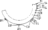
Fig. 7 is the circumferential view along the expansion of the friction damping device of the line among Fig. 3 22;
Fig. 7 A is 7 partial enlarged view, and the in relative rotation position of second scope of friction damping device 50 between flywheel body 11 and 12 is shown;
Fig. 7 B is the partial enlarged view of Fig. 7, and the in relative rotation position of three scope of friction damping device 50 between flywheel body 11 and 12 is shown;
Fig. 8 A and 8B represent improved friction damping device;
Fig. 9 represents improved second friction member;
Figure 10 is the longitudinal section view of the another kind of form of friction damping device of the present invention;
Figure 11 is the radial cross-section of another form of damping device of the present invention;
Figure 11 A is the radial cross-section of a kind of improved form of damping device shown in Figure 11;
Figure 12 is the radial cross-section of another form of damping device of the present invention;
Figure 13 be among Figure 12 rubbing device along the amplification radial view of arrow W direction;
Figure 14 is the axial view along the arrow below of the 3rd friction member among Figure 12;
Figure 15 first rubs and covers the axial view along arrow D direction of part among Figure 12;
Figure 16 is the radial cross-section of the CC direction along the line of first friction washer among Figure 15;
Figure 17 is the axial sectional view that a twin mass flywheel is in how much neutral positions, and the friction damping device that it has adopted the another kind of form of the present invention illustrates relevant bent axle along arrow G direction among Figure 18;
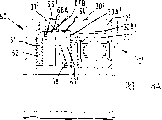
Figure 18 is the radial cross-section along Figure 17 center line V-V;
Figure 19 is the axial view along a side plate of arrow G direction among Figure 18;
Figure 19 A is the partial view of the H-H along the line of Figure 19 latus inframedium;
Figure 20 is the axial view along a flange plate of arrow G direction among Figure 18;
Figure 21 is the radial cross-section along Figure 17 center line W-W;
Figure 22 is a kind of localized axial view of improved form of the friction damping device of Figure 17.
Referring to Fig. 1-7B in the accompanying drawing, show a kind of twin mass flywheel 10, this twin mass flywheel is made up of two flywheel body 11 and 12.
A flywheel body 11 (being known as the input flywheel body again) is fixed on the bent axle (not shown) of this internal-combustion engine by a central hub 14 and bolt 18.In use a friction clutch (not shown) is fixed on second flywheel body 12 (being known as the output flywheel body again), so that this second flywheel body gear-box (not shown) relevant with links together.
Under normal transmission and overspeed condition, from shown in Figure 1, twin mass flywheel 10 clockwise rotates along direction shown in the arrow E.
Can relatively rotate between two flywheel body 11 and 12, and mainly be by a plurality of pivot connectors 40,46 controls of a plurality of torsion device, and by friction damping device 50 controls of the present invention.
The work of pivot connector 40 does not belong to the application's design.The complete work that discloses this pivot connector in the applicant's B. P. GB2229793 in first to file.
In a word, link 40 comprises a first connecting rod 41, and this connecting rod 41 pivotally is installed between the pivot plate 31 of central hub part 33 and flywheel body 12 by first pivot 43, and second connecting rod 42 is installed on the flywheel body 11 by moment device 46 by second pivot 44.Two connecting rods 41 and 42 are interconnected rotationally by the 3rd pivot 45.First connecting rod 41 is made into bob-weight body bodily form formula, and its quality away from first pivot pin end, 43 places is bigger.
Relatively rotating of flywheel body makes each link be in diverse location shown in Figure 1, but acts on centrifugal force on the link and the answer bias effect of moment device 46 can make this link recover it in position shown in Fig. 1.
The work of moment device 46 is not theme part of the present invention, and as mentioned above, the moment device can hinder the rotation of connecting rod 42 around pivot 44.In the applicant's UK Patent Application formerly 9416891.1 full disclosure install 46 work.
Work to friction damping device 50 describes below.
Described friction damping device comprises the element that (see figure 4) is from left to right installed in the following order:
A) the annular surface 15R (see figure 4) on the main cover plate 15.
B) friction member 51 (being known as the driven member and second friction member again) (seeing Figure 4 and 5 A), it has a discoid body 52, and this discoid body has surperficial 52R, 52L, and some jaws 53.Jaw 53 circumferential compartment of terrains be distributed in discoid body 52 around.The plane of jaw 53 is perpendicular to the plane of discoid body 52.Each jaw has two forks gang 54 and fork base 55 (Fig. 7).Each fork thigh has an external common transmission system CDF and inside first a transmission system DFI.Should be pointed out that the plane by pitching base 55 does not overlap with the surperficial 52R of discoid body 52, but on the direction of fork thigh 54, depart from.
C) friction member 56 (being known as driving component and the 3rd friction member again) (Figure 4 and 5), it has a ring bodies 57, and this ring bodies has a left annular surface 57L and right annular surface 57R, and a radially inwardly outstanding post 58.Ring bodies 57 is divided into two pairs of quadrants 59 and 60.Quadrant 59 is just in time relative, and with post 58 coplanars.Quadrant 60 also is relative, and coplanar, but departs from the plane of quadrant 59 in the axial direction.Circumferentially adjacent quadrant is connected by oblique tube 61.
D) friction member 62 (being known as the driven member and first friction member again) (seeing Fig. 4 and 6), it and the 3rd friction member 56 are similar, and that different is post 65A, the 66A that it has some radially outwards to stretch out, but the post that does not extend radially inwardly.Friction member 62 has a ring bodies 63, and this ring bodies has a left annular surface 63L and right annular surface 63R.Ring bodies 63 is to connect shoulder body 65 and 66 by oblique tube 67 to form, and is corresponding with the corresponding body on the 3rd friction member 56.Post 65A and quadrant 65 coplanars, and post 66A and quadrant 66 coplanars.Each post 65A, 66A have one first transmission system DFA.
E) cup spring 68 (see figure 4)s.An available wave washer (being known as wavy spring again) replaces this cup spring 68 in another embodiment.
F) friction member 69 (being known as driven member again) (seeing Fig. 3 and 4), the post 71 that it has a ring bodies 70 and extends radially outwardly in this ring bodies periphery.Each post 71 has transmission system DFC.At interior Zhou Youyi thickened portion 72 of ring bodies 70, this part has a shoulder body 73.From Fig. 4, be an annular surface 69R at the right-hand side of friction member 69.
G) an annular surface 14L on the wheel hub 14.
From Fig. 1, align at the element of the geometrical center position of twin mass flywheel 10 (promptly the first and the 3rd pivot aligns with the radial plane of twin mass flywheel 10) friction damping device, shown in Fig. 3 and 4, particularly:
A) the transmission system DFB engagement of the public transmission system CDF of fork thigh 54 and flywheel body 12.Transmission system DFB is the groove 80 that is located on the pivot plate 31.This can guarantee that second friction member 51 is to be fixed together with the pivot plate 31 of flywheel body 12 rotationally.
B) post 58 of the 3rd friction member 56 is rotatably mounted in the groove 81 of wheel hub 14.
C) because the transmission system DF1 engagement of the transmission system DFA of post 65A, 66A and second friction member 51, first friction member 62 is concentric and be rotatably mounted to second friction member 51.In addition, first friction member 62 only leans against on the fork base 55 of second friction member 51 at post 65A place.Sector 59 and 60 on the 3rd friction member 56 aligns with the quadrant 65 and 66 on first friction member 62 respectively, the lit range between second friction member and first friction member so that the 3rd friction member 56 can float vertically, that is: sector 59 aligns with quadrant 65 substantially, and quadrant 60 is alignd with quadrant 66 substantially, so that its interlaced (Fig. 7).As can be seen, fork base 55 contact with post 65A, plays a part to limit the stop member of the radial motion of first friction member, 62 relative the 3rd friction members 56, and plays maintenance cup spring 68 and be in pressurized state (seeing below).
D) cup spring 68 is coaxial and be attached on this friction member with first friction member 62, and first friction member 62 is biased into the left side of Fig. 4 and 7.Cup spring is by axial compression and be in pressurized state (with unrestricted not pressurized state is opposite fully in radial direction).
E) friction member 69 and cup spring 68 are coaxial and be attached on this spring.Keep cup spring 68 and friction member 69 to be in coaxial state by the shoulder shape part 73 of being close to cup spring 68 inner edges.The post 71 of friction member 69 is matched with between the two fork thighs of second friction member.Guarantee that thus friction member 69 is fixed on second friction member 51 rotationally.
Be understandable that the 3rd friction member 56 is to be rotatably connected to cover plate 15 and the wheel hub 14 of importing flywheel body 11.In addition, second friction member 51, first friction member 62, cup spring 68 and friction member 69 are rotatably mounted on the pivot plate 12 of output flywheel body 12.
This friction damping device 50 has successively first, second and the third phase that link to each other to slewing area along transmission and hypervelocity direction between flywheel body 11 and 12.
Along on the direction of transmission or hypervelocity, in first scope in relative rotation, post 65A keeps being close on the adjacent fork base 55, because quadrant 59,60 and 65,66 correspondingly keeps interlaced.In this first scope, flywheel body 11 and 12 relatively rotate between the ring surface 52L that causes annular surface 15R and engagement and the annular surface 69R of engagement and annular surface 14L between initial surface friction drag of generation.This surface friction drag produces a frictional damping moment (radius that depends on surperficial 15R, the 52L, 14L and the 69R that produce friction).The moment that is produced because of rubbing between surperficial 15R and the 52L is through second friction member 51, and more particularly the public transmission system CDF of second friction piece 51 that contacts by the transmission system DFB with pivot plate 31 reaches flywheel body 12.
The transmission system CDF of the transmission system DFC of the friction member 69 that the moment that produced because of rubbing between surperficial 14L and the 69R keeps in touch through the transmission system DF1 with second friction member 51 and second friction member 51 that keeps in touch with the transmission system DFB of pivot plate 31 reaches flywheel body 12.
Transmission system DFC and DF1 only transmit because of the moment that friction produced between surperficial 14L and the 69R, and transmission system CDF and DFB can transmit between surperficial 14L and the 69R and all moments that produced between surperficial 15R and the 52L.Relevant problem when above-mentioned total frictional damping moment is designed to overcome and moves under crawl speed with engine such as during gear idle running.
Along transmission or the hypervelocity direction second scope in relative rotation in (Fig. 7 A), the corresponding oblique tube 61 and 67 on friction member 56 and 62 is in contact with one another, so that first friction member 62 moves right along direction shown in the arrow K among Fig. 7 A.Post 65A no longer contacts with fork base 55.This makes cup spring 68 that first friction member 62 is biased into the 3rd friction member 56, and the 3rd friction member 56 is biased on second friction member 51, and second friction member 51 continues to be biased on the main cover plate 15.
In the 3rd scope of edge driving or hypervelocity direction, the top of oblique tube arrives, and quadrant 60 contact segments 65 (seeing Fig. 7 B).The total frictional damping moment that is produced by relatively rotating of flywheel body 11 and 12 in the 3rd scope can not fluctuate, because relatively rotate the length that can not change cup spring 68 in this scope.
Second with the 3rd scope in total frictional damping moment of being produced be designed to foot in restriction and the transmission of twin mass flywheel 10 or the relevant problem that exceeds the speed limit.
Second and the third phase moment that engagement is produced to other friction surface of slewing area internal cause reach flywheel body 11 by the post 58 of the 3rd friction member 56.Reach flywheel body 12 by the moment that friction produced between second friction member 51 and the 3rd friction member 56 by transmission system CDF and DFB.By the moment that is produced between the 3rd friction member 56 and the first friction member 62 transmission system DFA through contact with transmission system DF1 earlier, the public transmission system CDF that contacts with transmission system DFB of warp reaches flywheel body 12 again.
Clearly, during the relatively rotating of twin mass flywheel, motion is to axial arranged, and the moment of transmitting can produce potential transmission system wear problem between transmission system DFA and DF1 between described surface.But, because second friction member 51 and first friction member 56 are all smaller, therefore can make and do not have a large amount of extra costs with the material with better wear-resisting property (as spring steel).
Be further appreciated that between transmission system CDF and DFB can not move axially, and the area of contact between transmission system CDF and the DFB is greater than total area of contact of transmission system DFA and DFC and transmission system DF1.Can on transmission system DFB, produce lower contact load like this, and make pivot plate 31 to make by intensity lower material such as low carbon steel.
Clearly, described friction damping device 50 has lower frictional damping level in first scope in relative rotation of flywheel body 11 and 12, and has higher friction damping level in the second and the 3rd scope in relative rotation.In addition, the transition between the adjacent scope is smoothly.
Can adjust to above-mentioned friction damping device or at other rubbing device that discloses with the bottom of this specification, be applied to the different damping level of various objectives with generation, for example:
I) each element of this friction damping device can have different friction surface coating layers, and for example, polytetrafluoroethylene (PTFE) or non-asbestos friction material are the product of B120 as the product code of being made by Ray bestos GmbH, or adopt agglomerated material.
Ii) initial the need pressurizeed to cup spring.
Iii) more or less friction member can be arranged.
Iv) can increase another group oblique tube, relatively rotate scope to produce the 4th and the 5th.
V) between the Contact Transmission system of suitable element, can produce finite quantity and rotate, promptly can lost-motion between these elements.
By circumferential position or the angle that changes each oblique tube, the range of described first and second and three scopes in relative rotation and position can relative flywheel body 11 and 12 position of rest change.Specifically, this friction damping device needn't enter the 3rd scope along transmission or hypervelocity direction.In addition, flywheel body 11 and 12 on the transmission direction relatively rotating angle and may be different from angle between the described position of rest and the second scope starting point on the hypervelocity direction between the starting point of the geometrical center position and second scope.
In addition, this friction damping device can produce the surface friction drag that is greater than or less than on the hypervelocity direction along transmission direction in the 3rd scope, for example, has the height that is different from the inclined surface that exceeds the speed limit by guaranteeing the transmission inclined surface.
Fig. 8 a represent an improved friction damping device 50 that is similar to friction damping device 50 ', its main difference is:
A) second friction member 51 ', have friction material be bonded in annular portion 52 ' two axial sides.
B) fork strand 54 ' extend through pivot plate 31 ' transmission system DFB ' and enter flywheel plate 30 ' recess 30A '.Flywheel plate 30 ' locate not have transmission system at recess 30A ', therefore, by all moments that friction damping device produced by pivot plate 31 ' reach flywheel body 12 '.The advantage of this design is can form transmission system DFB on thin pivot plate by a punching operation more conveniently.But, this single punching operation be difficult to flywheel plate 30 ' on implement, and can weaken bearing flange 30B ' and bearing outer ring 30C '.
Therefore, twin mass flywheel 10 ' compact in the axial direction, output flywheel 12 ' mainly synthetic two-part, be pivot plate 31 ' and flywheel plate 30 ', pivot plate 31 ' only some has transmission system, and second friction member of axial orientation stretches into the recess of another parts (flywheel body 30 ') with normal gapped form.
C) post 65A ' do not contact fork base 55 '
D) cup spring 68 ' originally be not stressed
E) friction member 69 ' an axial sides be bonded with friction material.
It is favourable adopting friction material in this friction damping device, and particularly it can produce more stable friction factor, and therefore, the variation of frictional force and friction torque is less in use.
Fig. 8 B representation class be similar to friction damping device 50 ' improved friction damping device 50 ", its main difference is:
A) the second frictional damping part 51 " annular portion 52 that an inclination is arranged "
B) the corresponding inclined-plane that the inclined-plane on the 3rd frictional damping part 56 " has and the second frictional damping part 51 " contacts
C) the first frictional damping part 62 " does not tilt, and be bonded with friction material on each axial sides
D) on friction member 69 " is rotatably mounted to wheel hub 14 ", and near first friction member 62 "
E) cup spring 68 " is positioned at friction member 69 " and hub flange 90 " between, " rotate therefore with flywheel body 11.
Fig. 9 representation class be similar to second friction member 51 ' improved second friction member, 51 , different is, it has another transmission system 91, its axial orientation and fork strands 54 " direction opposite, and with the transmission system 92A engagement of friction member 92.Friction member 92 has and is bonded in a friction material on the axial sides.
Should be pointed out that friction member 92 is flat, and the transmission system of slope-less or axial orientation, this helps the adhesive friction material.Therefore, the moment that is produced by friction material 93 is reached friction member 92 by other transmission system, is reached second friction member 51 again.
This design helps providing the friction material that is rotatably mounted on second element, 51 , but this friction material preferably is used on the flat element (friction member 92).
Figure 10 representation class is similar to the friction damping device 150 of the another kind of form of friction damping device 50, but the end 154A of the fork thigh 154 of second friction member 151 distortion is formed on the local accessory that friction damping device 150 is packed into before the twin mass flywheel and to be made up of friction member 69, cup spring 68 and first and second and three friction members 62,151,56.
Figure 11 representation class is similar to the friction damping device 250 of the another kind of form of friction damping device 50, but the fork thigh 254 on second friction member 251 is flexible, and hook-like ends 254A is arranged.The elastic performance of fork thigh 254 makes friction damping device 250 can clamp before being assembled into twin mass flywheel and forms local accessory.
Figure 11 a representation class be similar to the friction damping device 250 of the another kind of form of damping device 250 ', different is that the axial distance q of local accessory outer surface is less than the spacing Q of adjacently situated surfaces on suitable cover plate 15 and the central hub 14.Clearly, in this embodiment, relevant flywheel body is not producing frictional damping moment in first scope in relative rotation basically, and this is favourable in some occasion.
The indicate friction damping device 450 of the another kind of form on the twin mass flywheel 410 that is contained in of Figure 12~16, described flywheel rotates (Figure 12) around axis N-N.
A) friction member 415A, it comprises the friction material 415B that is bonded on the thrust plate 415C.Friction member 415A is rotatably mounted on the main cover plate 415 by post 415D, and post 415D cooperates with jut 415E on protruding in cover plate 415.
B) friction member 451, have a discoid body 452, and this discoid body has right surperficial 452R and left surface 452L respectively, and some jaws 453.Friction member 451 can endwisely slip, and is rotatably mounted on the pivot plate 431 by jaw 453, and jaw 453 meshes with the transmission system 431A of pivot plate 431.
C) by 8 fork 400c, particularly by with wheel hub 414 on the public transmission system 4CDF of the fork 400c that meshes of the transmission system formed of 8 axial grooves 481 be rotatably mounted to friction member 400 (being known as second friction member again) on the wheel hub 414.Two axial sides at friction member 400 are fixed with two rubbing surface 400A and 400B.Rubbing surface 400A and 400B have annular surface 400L and 400R respectively.
D) friction member 462 (seeing Figure 14) (being known as the 3rd friction member again) is rotatably mounted on the pivot plate 431 by the outside jaw 462A (seeing Figure 12) with transmission system 431A engagement.The 3rd friction member 462 structurally is similar to first friction member 62, but it is to connect two groups of 8 sectors 465,466 by two groups of 8 oblique tubes 467, rather than is connected with 4 tiltlers by 4 quadrants of a friction member 62.Friction member 462 has right annular surface 463R and left annular surface 463L respectively.
E) friction member 456 (being known as first friction member again), it has a ring bodies 457 and circumferentially spaced oblique tube, and it is the radial rib 460L (seeing Figure 12,13,15 and 16) that is located on first axial sides.
On second axial sides of friction member 456, axially relative rib 460L has 8 circumferentially spaced jaws to 401 substantially.
8 circumferential arcuate rib 402 are also arranged on second axial sides of first friction washer.
F) cup spring 468 (being known as first friction member again) is cooperated by its element with 8 outside handgrip 468A and 8 inner handgrip 468B bias voltage friction generating means.Each outside handgrip 468A is bonded between a pair of jaw 401 with the circular gap of minimum.Clearly, outside handgrip 468A can guarantee that when engaging with jaw 401 friction washer 456 and cup spring 468 are concentric and be rotatably mounted on this spring.
In the another kind of structure of cup spring, one or two outside handgrip 468A can only be arranged or one or two inner handgrip 468B is only arranged, guarantee that with this friction member 456 is rotatably mounted on the wheel hub 414, but not necessarily concentric with it.
Geometrical center position in flywheel body 411 and 412, cup spring 486 are by axial pressure, and left axial surface 468L contact radius T place contact outside first friction washer 456, right axial surface 486R is at interior contact radius t place contact hub flange 414A.T is called as the cup spring ratio with the ratio of t, and greater than 1.Should be pointed out that circumferential arcuate rib 402 is radially between outer contacting radius T and interior contact radius t.
But, because the axial motion of friction member 456 relative the 3rd friction members 462 is flywheel body 411 and 412 results in relative rotation, and because the interior pawl 468B of cup spring 468 is an arc as Figure 12, along with the curved portion of interior pawl rolls on hub flange 414A, interior contact radius t increases.This can cause Bei Shi than reducing gradually, thereby the ratio of the power that makes this spring and deviation characteristic is different from the spring than work with fixing Bei Shi.This is favourable under some working state.
The further axial motion that friction member 456 leaves the 3rd friction member 462 makes circumferential arcuate rib 402 contact Belleville springs 468.This has the effect of unexpected reduction outer contacting radius T, and therefore causes the reduction gradually of Bei Shi ratio.
This progressively variation of Bei Shi ratio is particularly conducive to the adjustment rubbing device to be adapted to specific use.
Be appreciated that also and can realize gradually changing of Bei Shi ratio in the mode that is different from pawl in the arc Bei Shi.For example, the outer pawl 468A of Bei Shi can be arc or hub flange 414A be arc, in addition, the mode that can also be different from the circumferential arcuate rib on first friction washer 456 realizes the progressively variation of Bei Shi ratio.For example, the circumferential arcuate rib on cup spring 468 or the hub flange 414A or another axial surface can obtain this result.
The axial motion that should be pointed out that friction member 456 makes cup spring move vertically substantially, but this cup spring also has a rotative component, and the rubbing contact between particularly inner handgrip 468B and the fork 400C mainly is rotational motion.
In addition, the moment that is produced by friction member 456 reaches cup spring 468 earlier by the public transmission system of second friction member 400, reaches the fork 400C of second friction member 400 again, reaches wheel hub 414 at last.The moment that is produced by second friction member 400 also reaches wheel hub 414 by public transmission system.The advantage of this embodiment is similar to the advantage of friction damping device 50, and particularly, it allows wearing and tearing damping member 400 and 486 to be made by the harder material such as spring steel, and wheel hub 414 can be made by the softer material such as low carbon steel.
In another kind of structure, can will have the cup spring of public transmission system as second friction member.
Defining another kind of mode of the present invention is that friction member 462 is described as secondary friction member, and friction member 456 is described as elementary friction member, transmits surface friction drag on it by biasing spring.
Defining another mode of the present invention is that friction member 462 is described as second oblique tube, and friction member 456 is described as first oblique tube, makes its joint by the bias voltage of cup spring 468.During the relatively rotating of relevant flywheel body, the Bei Shi of cup spring 468 is than changing along with relatively rotating of oblique tube.
Referring to the Figure 17 in the accompanying drawing~21, disclosed the another kind of form of the friction damping device 650 that is used for twin mass flywheel 610.Twin mass flywheel comprises two flywheel body 611 and 612.
Two flange plate 631,632 are mirror image each other, and a flange plate 631 as shown in figure 20.Two flange plate 631 and 632 respectively have an internal annular section 635 radially, the ear 636 of radially extending is relatively arranged on it, radially be provided with and axially depart from annular portion 635, with when with rivet 637 two dishes 631 and 632 being leaned against when being fixed on the hub member 630 privately, each coils the ear of aiming on 631 and 632 and leans on mutually.There are faying surface 636A and 636B and shaped tab portions 636C in each ear 636.
In another kind of structure, can play the effect of a pair of flange plate 631,632 by a flange plate.
By bearing 619 second flywheel body 612 is installed in rotation on first flywheel body 611.Bearing 619 is nonrotatably mounted tO on the wheel hub 614, and is positioned between the flange 614A and annular slab 628 of wheel hub.The outer ring of bearing 619 is nonrotatably mounted tO the middle part of second flywheel body 612 by stationary fit.
Relatively rotating between two flywheel body 611 and 612 mainly is by some pivot connectors 640 and friction damping device 695 controls.In addition, spring 660, first elastic device 670, second elastic device 680, damping device 690 and two friction damping devices of the present invention 650 are assisted control flywheel body 611 and 612 each concrete scope in relative rotation.
Pivot connector 640 is worked in the mode of the pivot connector 40 that is similar to twin mass flywheel 10, it has respectively first link 641 (forming bob-weight body body), second link (642) corresponding to first link 41, second link 42 and first and second and three pivots 43,44 and 45, and first and second and three pivots 643,644 and 645.
Figure 17 represents that described link is in its centrifugal middle position, and promptly the center of gravity CG of each first link 641 and corresponding first pivot 643 aligns on the radial plane of twin mass flywheel 610.This is the state that is adopted when twin mass flywheel rotates and do not transmit any moment.
Each friction damping device 650 (seeing Figure 21) comprises an elastic clip 651, and its cross section is a U-shaped, and the component 653 of a base portion 652 and two arcs is arranged.Base portion is fixed on first spring seat 622 by rivet 663.First spring seat 622 is positioned at an annular end of side plate 626,627 upper spring grooves 628, and the effect reaction by pressing spring 660 is on second spring seat 623, and be fixed in rotationally on the flywheel body 611, when flywheel 610 remained static, this second spring seat 623 interacted with another circumferential end of spring groove 628.
Each the outer side surface 653A contact side plate 626 of arm shape part 653 or the axial internal surface of side plate 627.
Each friction damping device 650 also comprises the surperficial 636C in the ear 636.
The faying surface 636A that will cause in the ear 636 along relatively rotating of transmission direction between the flywheel body 611 and 612 is near its corresponding second spring seat 623.In some occasion, flywheel body 611 will cause contacting of described faying surface 636A and second spring seat 623 with 612 along further relatively rotating of transmission direction, pressure spring 660 thus, and the 636C of ear enters between folder 651 the corresponding component 653 and contact surface 653B then.
Therefore, relatively rotating of flywheel body 611,612 finally is by a fixing transmission retainer (rivet 663 and a buffering hypervelocity stopping device (elastic device 680)) restriction.
Another kind of structure can have a fixing or snubber or stopper bushing that is used for transmission or hypervelocity direction, and this retainer can be installed on any flywheel body.Under the state of relatively rotating, two flywheel body are the restrictions that are subjected to the transmission retainer, ten fens appropriate sections near wheel hub 614 of the protruding 641A of each bob-weight body 641.Disadvantageous production tolerance will make the relevant portion of one of above-mentioned protruding 641A contact wheel hub and produce noise.The damping device that is installed on each bob-weight body can stop any this type of noise of generation, can also guarantee that this link can not surpass mid point, and promptly pivot 645 can be by connecting the line of pivot 643 and 644.Other embodiment can provide the damping device that is installed on the hub portion, and can on wheel hub or bob-weight body damping device be installed, with avoid when two flywheel body be by the hypervelocity stopping device when limiting the bob-weight body contacting under the state in relative rotation with wheel hub.
In another kind of structure, friction damping device 695 can by one such as 50 or 50 ' friction damping device of the present invention replace.
Referring to the Figure 22 in the accompanying drawing, show another kind of friction damping device 750.
Clearly, friction damping device 650 and 750 characteristics combination can produce another kind of structure, and wherein, two friction surfaces of elastic clip can be separated from one another along a radial line, or two friction surfaces of elastic clip can move toward each other.
Claims (20)
1. friction damping device, it can produce the friction torque in relative rotation of first and second flywheel body that are used to control twin mass flywheel, this friction damping device comprises one first and one second friction member, it operationally is connected with a flywheel body by a public transmission system, this transmission system constitutes the part of second friction member, with one the 3rd friction member, it is sandwiched between first and second friction members and operationally is connected with other flywheel body, it is characterized in that this friction damping device also comprises drive unit, its effect is to make the axial motion relative to one another of first and second friction members, changing the frictional force that this device is produced when first or second friction member rotates at the 3rd friction member, above-mentioned relatively rotating is the generation that relatively rotates by flywheel body.
2. friction damping device as claimed in claim 1 is characterized in that described first friction member is because of relatively rotating of flywheel body and with respect to relevant flywheel axial motion.
3. friction damping device as claimed in claim 1 is characterized in that second friction member has a disc-shaped part and one or several to comprise the part of the axial orientation of public transmission system.
4. friction damping device as claimed in claim 3, the part that it is characterized in that each first axial orientation are the form of the fork that has strand, and the outer surface of this fork thigh plays the effect of public transmission system.
5. friction damping device as claimed in claim 4 is characterized in that first friction member has a system between the fork thigh that is engaged in second element.
6. friction damping device as claimed in claim 4, it is characterized in that second friction member also has one second axial orientation part, its orientation is opposite with the axial direction of above-mentioned first portion, but also comprises that another is used for the transmission system that other friction member is connected with second friction member.
7. friction damping device as claimed in claim 1 is characterized in that comparing with the material of relevant flywheel, and the material of second friction member is harder.
8. friction damping device as claimed in claim 3, it is characterized in that one of first and second flywheel body are divided into two parts, a part wherein directly is operably connected under second friction member by public transmission system, and the axial orientation of second friction member part stretches in the groove of another part with gapped form.
9. friction damping device as claimed in claim 1, the axial motion that it is characterized in that relative second element of first element is to be caused by the contact between the oblique tube on the adjacent friction member.
10. friction damping device as claimed in claim 9 it is characterized in that described oblique tube is designed to have at least two continuous scopes in relative rotation, and the frictional damping moment that produces is different in adjacent scope.
11. friction damping device as claimed in claim 9 is characterized in that described second friction member has the inclined-plane.
12. friction damping device as claimed in claim 9 is characterized in that described first friction member has the inclined-plane.
13. friction damping device as claimed in claim 1 is characterized in that a spring bias voltage friction member engages friction member, and plays the effect that the frictional force that will be produced by first friction member reaches public transmission system.
14. friction damping device as claimed in claim 1 is characterized in that having other friction member that can operationally be connected with corresponding flywheel body, so that this device is many plates (multi-plate) friction damping devices.
15. friction damping device as claimed in claim 1 is characterized in that described second element can rotate a limited amount relative to first element or relative to relevant flywheel.
16. friction damping device as claimed in claim 1 is characterized in that some rubbing device element is built into pre-assembled local parts, so that insert as a unitary element in the assembling of this twin mass flywheel.
17. as the friction damping device of claim 16, it is characterized in that described pre-assembled local parts comprise axial pre-tensioned biased member, and, when this single device inserts twin mass flywheel, the axial compression that this biased member can not add.
18., it is characterized in that second friction member has a disc-shaped part and one or several to comprise the part of axial orientation of public transmission system and described rubbing device element is remained on the element of first axial orientation by system as local parts end as the friction damping device of claim 16.
19. friction damping device in relative rotation that is used to control first and second flywheel body of twin mass flywheel, it is characterized in that this rubbing device comprises a folder that is substantially U-shaped, have a base portion and two and be fixed in an arm portion on the flywheel body rotationally, and the flange that is fixed together with another flywheel body rotationally, the arm contact that described flange presss from both sides with U-shaped after described flywheel body relatively rotates a prearranging quatity also produces frictional force.
20. friction damping device in relative rotation that is used to control first or second flywheel body of twin mass flywheel, this friction damping device comprises first friction element that rotates with a flywheel body, this friction member is biased into second friction element that rotates with another flywheel body by a cup spring and engages, to produce surface friction drag, it is characterized in that during above-mentioned the relatively rotating of flywheel body, cup spring is compressed, so that the Bei Shi ratio, promptly described cup spring changes with the ratio of this cup spring with the interior contact radius of second adjacent element with the outer contacting radius of first adjacent element.
Applications Claiming Priority (2)
| Application Number | Priority Date | Filing Date | Title |
|---|---|---|---|
| GBGB9505750.1A GB9505750D0 (en) | 1995-03-21 | 1995-03-21 | A twin mass flywheel friction damping device |
| GB9505750.1 | 1995-03-21 |
Publications (2)
| Publication Number | Publication Date |
|---|---|
| CN1191595A CN1191595A (en) | 1998-08-26 |
| CN1083953C true CN1083953C (en) | 2002-05-01 |
Family
ID=10771623
Family Applications (1)
| Application Number | Title | Priority Date | Filing Date |
|---|---|---|---|
| CN96194025A Expired - Fee Related CN1083953C (en) | 1995-03-21 | 1996-03-21 | Twin mass flywheel friction damping device |
Country Status (9)
| Country | Link |
|---|---|
| US (1) | US6209419B1 (en) |
| EP (2) | EP0812399B1 (en) |
| JP (1) | JPH11502287A (en) |
| KR (1) | KR19980703152A (en) |
| CN (1) | CN1083953C (en) |
| BR (1) | BR9607913A (en) |
| DE (2) | DE69618822D1 (en) |
| GB (2) | GB9505750D0 (en) |
| WO (1) | WO1996029525A1 (en) |
Cited By (1)
| Publication number | Priority date | Publication date | Assignee | Title |
|---|---|---|---|---|
| KR20150006366A (en) * | 2013-07-08 | 2015-01-16 | 발레오 앙브라이아쥐 | Double damping flywheel with improved damping means |
Families Citing this family (28)
| Publication number | Priority date | Publication date | Assignee | Title |
|---|---|---|---|---|
| GB9620036D0 (en) * | 1996-09-26 | 1996-11-13 | Automotive Products Plc | A friction damper |
| GB2321947B (en) * | 1996-09-26 | 2000-06-28 | Automotive Products Plc | Friction plates for use in a friction damper. |
| EP0904502A2 (en) | 1997-03-27 | 1999-03-31 | Automotive Products Public Limited Company | Bearing arrangement of a twin mass flywheels |
| DE19713132A1 (en) * | 1997-03-27 | 1998-10-01 | Mannesmann Sachs Ag | Torsion vibration damper for especially vehicle clutch |
| GB9707928D0 (en) * | 1997-04-18 | 1997-06-04 | Automotive Products Plc | Vehicle drivelines |
| GB2329950A (en) * | 1997-04-18 | 1999-04-07 | Automotive Products Plc | Torsionally resilient means in vehicle drivelines |
| FR2771786B1 (en) * | 1997-11-28 | 2000-02-11 | Valeo | TORSION DAMPING DEVICE AND FRICTION UNIT ASSEMBLY FOR SUCH A DEVICE |
| DE19929940A1 (en) * | 1999-06-29 | 2001-01-18 | Mannesmann Sachs Ag | Clutch disc |
| ATE344405T1 (en) * | 2003-03-27 | 2006-11-15 | Luk Lamellen & Kupplungsbau | TORSIONAL VIBRATION DAMPER |
| GB0314084D0 (en) * | 2003-06-18 | 2003-07-23 | Automotive Prod Italia | Twin mass flywheels |
| DE102005012861A1 (en) * | 2005-01-26 | 2006-08-03 | Rohs, Ulrich, Dr.-Ing. | Damping device particularly for dual mass flywheel has friction device between first and second component where first component and a third component are mounted between two spaced surfaces |
| ATE525590T1 (en) * | 2007-02-12 | 2011-10-15 | Schaeffler Technologies Gmbh | METHOD FOR REDUCING VIBRATIONS OF AN OVERALL ANNUAL DISC-SHAPED COMPONENT AND ANNUAL DISC-SHAPED COMPONENT |
| JP2008082556A (en) * | 2007-11-30 | 2008-04-10 | Aisin Seiki Co Ltd | Torque fluctuation absorbing device |
| DE112009005528B4 (en) * | 2008-07-24 | 2020-08-13 | Exedy Corp. | Damping mechanism and flywheel assembly |
| KR101020814B1 (en) * | 2008-11-28 | 2011-03-09 | 현대자동차주식회사 | DUAl MASS FLY WHEEL |
| WO2010074752A1 (en) * | 2008-12-22 | 2010-07-01 | Progressive Flywheel Energy, Inc. | Flywheel energy storage battery |
| JP5656949B2 (en) * | 2012-10-01 | 2015-01-21 | トヨタ自動車株式会社 | Damper device for vehicle |
| KR101472435B1 (en) * | 2013-06-28 | 2014-12-12 | 주식회사평화발레오 | Dual mass damper flywheel |
| CN107023609A (en) * | 2016-01-29 | 2017-08-08 | 南京法雷奥离合器有限公司 | For automobile clutch disk or the torsional vibration damper of double mass flywheel |
| FR3079574B1 (en) * | 2018-03-30 | 2020-09-04 | Valeo Embrayages | TORSION DAMPING DEVICE WITH MAIN SHOCK ABSORBER AND ADDITIONAL SHOCK ABSORBER |
| CN110388409A (en) * | 2018-04-19 | 2019-10-29 | 南京法雷奥离合器有限公司 | Torsion damping damper |
| CN110439968B (en) * | 2018-05-04 | 2023-04-07 | 南京法雷奥离合器有限公司 | Torsional vibration damping system |
| DE102018119285A1 (en) * | 2018-08-08 | 2020-02-13 | Schaeffler Technologies AG & Co. KG | Drive system with damper arrangement provided therein |
| CN113557373B (en) * | 2019-04-18 | 2023-09-22 | 舍弗勒技术股份两合公司 | Shock absorber for vehicle and vehicle |
| WO2021052631A1 (en) * | 2019-09-17 | 2021-03-25 | Eaton Intelligent Power Limited | Variable main damper hysteresis pack |
| CN112706788A (en) * | 2021-01-18 | 2021-04-27 | 中车工业研究院有限公司 | Elastic transmission device of motor and wheel pair, bogie and motor car |
| DE102021122868A1 (en) | 2021-09-03 | 2023-03-09 | Schaeffler Technologies AG & Co. KG | torsional vibration damper |
| DE102021122870B3 (en) | 2021-09-03 | 2022-12-22 | Schaeffler Technologies AG & Co. KG | torsional vibration damper |
Citations (6)
| Publication number | Priority date | Publication date | Assignee | Title |
|---|---|---|---|---|
| GB2127131A (en) * | 1982-09-16 | 1984-04-04 | Daikin Mfg Co Ltd | Damper disc |
| US4782933A (en) * | 1985-03-27 | 1988-11-08 | Luk Lamellen Und Kupplungsbau Gmbh | Apparatus for compensating for fluctuations of torque between coaxial flywheels in a motor vehicle |
| US4867290A (en) * | 1988-09-02 | 1989-09-19 | Ford Motor Company | High excursion torsional vibration damper for controlled energy absorption |
| GB2265437A (en) * | 1992-03-27 | 1993-09-29 | Automotive Products Plc | Twin mass flywheel |
| DE4341371A1 (en) * | 1992-12-08 | 1994-06-09 | Valeo | Torsional vibration damper, in particular for motor vehicles |
| WO1994020769A1 (en) * | 1993-03-05 | 1994-09-15 | Automotive Products Plc | A twin mass flywheel |
Family Cites Families (26)
| Publication number | Priority date | Publication date | Assignee | Title |
|---|---|---|---|---|
| US3483888A (en) * | 1967-12-15 | 1969-12-16 | Waldes Kohinoor Inc | Self-locking retaining rings and assemblies employing same |
| US3788429A (en) * | 1972-07-14 | 1974-01-29 | Gmc Co | Disc brake and wheel assembly |
| US4101015A (en) * | 1976-12-29 | 1978-07-18 | Borg-Warner Corporation | Vibration damper with variable spring rate and damping friction |
| US4300669A (en) * | 1979-10-15 | 1981-11-17 | Borg-Warner Corporation | Cushion finger diaphragm spring clutch |
| DE3004663C2 (en) * | 1980-02-08 | 1982-04-01 | Halbach & Braun, 5600 Wuppertal | Planer drive |
| FR2532705B1 (en) * | 1982-09-07 | 1987-04-03 | Valeo | TORSION DAMPING DEVICE, IN PARTICULAR A CLUTCH FRICTION, IN PARTICULAR FOR A MOTOR VEHICLE |
| DE3306281A1 (en) * | 1983-02-23 | 1984-08-23 | Fichtel & Sachs Ag, 8720 Schweinfurt | Torsional vibration damper with a kinked spring characteristic for the generation of friction |
| DE3448510C2 (en) * | 1983-11-15 | 1996-12-05 | Luk Lamellen & Kupplungsbau | IC engine torque variation compensator |
| US5374218A (en) * | 1983-11-15 | 1994-12-20 | Luk Lamellen Und Kupplungsbau Gmbh | Assembly for compensation of fluctuations of torque |
| US5180335A (en) * | 1984-06-12 | 1993-01-19 | Luk Lamellen Und Kupplungsbau Gmbh | Torsion damping assembly for use with clutches in motor vehicles |
| DE8525579U1 (en) * | 1985-09-07 | 1993-06-03 | Luk Lamellen Und Kupplungsbau Gmbh, 7580 Buehl, De | |
| DE3621997A1 (en) * | 1986-07-01 | 1988-01-07 | Freudenberg Carl Fa | FLYWHEEL |
| DE3740570A1 (en) | 1986-12-04 | 1988-06-09 | Tochigi Fuji Sangyo Kk | Disc flywheel |
| FR2609132B1 (en) * | 1986-12-24 | 1991-03-08 | Valeo | SHOCK ABSORBER FOR TRANSMISSION, ESPECIALLY FOR MOTOR VEHICLES |
| DE3704643A1 (en) * | 1987-02-14 | 1988-08-25 | Daimler Benz Ag | SHARED FLYWHEEL |
| JPH0792114B2 (en) * | 1987-04-15 | 1995-10-09 | 株式会社大金製作所 | Flywheel assembly |
| DE3743801A1 (en) * | 1987-12-23 | 1989-07-06 | Daimler Benz Ag | SHARED FLYWHEEL |
| US4856638A (en) * | 1988-08-08 | 1989-08-15 | General Motors Corporation | Clutch damper with friction lag |
| DE3909234C1 (en) * | 1989-03-21 | 1990-05-31 | J.M. Voith Gmbh, 7920 Heidenheim, De | |
| US5362276A (en) * | 1992-09-02 | 1994-11-08 | General Motors Corporation | Selective torque clipping mechanism |
| FR2706963B1 (en) * | 1993-06-25 | 1995-09-15 | Valeo | |
| FR2714948B1 (en) * | 1993-11-15 | 1996-03-08 | Valeo | Shock absorber steering wheel, especially for motor vehicles. |
| ES2122823B1 (en) * | 1993-11-26 | 2000-02-01 | Fichtel & Sachs Ag | TORSION VIBRATION DAMPER IN THE DRIVE CHAIN OF AN AUTOMOBILE, WITH AXIAL TENSIONED FRICTION RING. |
| FR2714434B1 (en) * | 1993-12-23 | 1996-02-09 | Valeo | Damping device intended to be integrated into a motor vehicle powertrain. |
| FR2725003B1 (en) * | 1994-09-28 | 1997-01-10 | Valeo | TORSION DAMPING DEVICE |
| JP3534953B2 (en) * | 1996-09-05 | 2004-06-07 | ジヤトコ株式会社 | Power transmission clutch structure |
-
1995
- 1995-03-21 GB GBGB9505750.1A patent/GB9505750D0/en active Pending
-
1996
- 1996-03-21 DE DE69618822T patent/DE69618822D1/en not_active Expired - Lifetime
- 1996-03-21 WO PCT/GB1996/000675 patent/WO1996029525A1/en not_active Application Discontinuation
- 1996-03-21 KR KR1019970706555A patent/KR19980703152A/en not_active Application Discontinuation
- 1996-03-21 EP EP96907601A patent/EP0812399B1/en not_active Expired - Lifetime
- 1996-03-21 EP EP99100523A patent/EP0909906B1/en not_active Expired - Lifetime
- 1996-03-21 US US08/913,658 patent/US6209419B1/en not_active Expired - Fee Related
- 1996-03-21 JP JP8528204A patent/JPH11502287A/en active Pending
- 1996-03-21 GB GB9718989A patent/GB2313648B/en not_active Expired - Fee Related
- 1996-03-21 CN CN96194025A patent/CN1083953C/en not_active Expired - Fee Related
- 1996-03-21 DE DE69609167T patent/DE69609167T2/en not_active Expired - Fee Related
- 1996-03-21 BR BR9607913A patent/BR9607913A/en active Search and Examination
Patent Citations (6)
| Publication number | Priority date | Publication date | Assignee | Title |
|---|---|---|---|---|
| GB2127131A (en) * | 1982-09-16 | 1984-04-04 | Daikin Mfg Co Ltd | Damper disc |
| US4782933A (en) * | 1985-03-27 | 1988-11-08 | Luk Lamellen Und Kupplungsbau Gmbh | Apparatus for compensating for fluctuations of torque between coaxial flywheels in a motor vehicle |
| US4867290A (en) * | 1988-09-02 | 1989-09-19 | Ford Motor Company | High excursion torsional vibration damper for controlled energy absorption |
| GB2265437A (en) * | 1992-03-27 | 1993-09-29 | Automotive Products Plc | Twin mass flywheel |
| DE4341371A1 (en) * | 1992-12-08 | 1994-06-09 | Valeo | Torsional vibration damper, in particular for motor vehicles |
| WO1994020769A1 (en) * | 1993-03-05 | 1994-09-15 | Automotive Products Plc | A twin mass flywheel |
Cited By (2)
| Publication number | Priority date | Publication date | Assignee | Title |
|---|---|---|---|---|
| KR20150006366A (en) * | 2013-07-08 | 2015-01-16 | 발레오 앙브라이아쥐 | Double damping flywheel with improved damping means |
| KR102265136B1 (en) | 2013-07-08 | 2021-06-16 | 발레오 앙브라이아쥐 | Double damping flywheel with improved damping means |
Also Published As
| Publication number | Publication date |
|---|---|
| DE69609167T2 (en) | 2001-03-08 |
| GB2313648A (en) | 1997-12-03 |
| CN1191595A (en) | 1998-08-26 |
| EP0909906A3 (en) | 1999-06-02 |
| WO1996029525A1 (en) | 1996-09-26 |
| KR19980703152A (en) | 1998-10-15 |
| JPH11502287A (en) | 1999-02-23 |
| GB2313648B (en) | 1999-07-14 |
| DE69618822D1 (en) | 2002-03-14 |
| GB9718989D0 (en) | 1997-11-12 |
| EP0909906A2 (en) | 1999-04-21 |
| EP0812399B1 (en) | 2000-07-05 |
| BR9607913A (en) | 1998-01-13 |
| DE69609167D1 (en) | 2000-08-10 |
| GB9505750D0 (en) | 1995-05-10 |
| EP0909906B1 (en) | 2002-01-23 |
| US6209419B1 (en) | 2001-04-03 |
| EP0812399A1 (en) | 1997-12-17 |
Similar Documents
| Publication | Publication Date | Title |
|---|---|---|
| CN1083953C (en) | Twin mass flywheel friction damping device | |
| CN101061328A (en) | Torsional vibration damper | |
| CN1072338C (en) | Flywheel, in particular for motor vehicles | |
| CN1227462C (en) | Self-adjusting clutch-release bearing | |
| CN1085801C (en) | Twin mass flywheel | |
| CN1532435A (en) | Torsional damper | |
| CN1372623A (en) | Poewr transmission mechanism | |
| CN1372624A (en) | Power transmission mechanism | |
| CN1676966A (en) | Engine mount | |
| CN1168169A (en) | Automatically adjusting clutch | |
| CN1945050A (en) | A friction clutch for a motor vehicle, and a pre-assembled module for such a friction clutch | |
| CN1902409A (en) | Telescopic shaft for vehicle steering | |
| CN1576638A (en) | Dustproof cover impingement plate and suspension mechanism with the same | |
| CN1082635C (en) | Twin mass flywheel | |
| US6306043B1 (en) | Motor vehicle double flywheel torsional damper | |
| CN1576627A (en) | Torsional vibration damper | |
| CN1746524A (en) | Device for coupling two shafts having an axial offset | |
| CN1934365A (en) | Clutch, especially for a motor vehicle, comprising an improved cover mechanism | |
| CN1693729A (en) | Power transmission device | |
| US5409423A (en) | Belt pulley | |
| CN1601142A (en) | Drive belt pulley and belt drive system | |
| FR2902165A1 (en) | DOUBLE SHOCKWHEEL, IN PARTICULAR FOR MOTOR VEHICLE | |
| CN101720290A (en) | Bushing assembly | |
| CN1105506A (en) | Friction lining holder disc, particularly for motor vehicles | |
| CN1065597C (en) | Clutch module with integrated securing screws |
Legal Events
| Date | Code | Title | Description |
|---|---|---|---|
| C06 | Publication | ||
| PB01 | Publication | ||
| C10 | Entry into substantive examination | ||
| SE01 | Entry into force of request for substantive examination | ||
| C14 | Grant of patent or utility model | ||
| GR01 | Patent grant | ||
| C19 | Lapse of patent right due to non-payment of the annual fee | ||
| CF01 | Termination of patent right due to non-payment of annual fee |