CN108348327B - Modular intraocular lens design, tools and methods - Google Patents
Modular intraocular lens design, tools and methods Download PDFInfo
- Publication number
- CN108348327B CN108348327B CN201680064319.8A CN201680064319A CN108348327B CN 108348327 B CN108348327 B CN 108348327B CN 201680064319 A CN201680064319 A CN 201680064319A CN 108348327 B CN108348327 B CN 108348327B
- Authority
- CN
- China
- Prior art keywords
- base
- lens
- tab
- intraocular lens
- lens system
- Prior art date
- Legal status (The legal status is an assumption and is not a legal conclusion. Google has not performed a legal analysis and makes no representation as to the accuracy of the status listed.)
- Active
Links
Images


Classifications
-
- A—HUMAN NECESSITIES
- A61—MEDICAL OR VETERINARY SCIENCE; HYGIENE
- A61F—FILTERS IMPLANTABLE INTO BLOOD VESSELS; PROSTHESES; DEVICES PROVIDING PATENCY TO, OR PREVENTING COLLAPSING OF, TUBULAR STRUCTURES OF THE BODY, e.g. STENTS; ORTHOPAEDIC, NURSING OR CONTRACEPTIVE DEVICES; FOMENTATION; TREATMENT OR PROTECTION OF EYES OR EARS; BANDAGES, DRESSINGS OR ABSORBENT PADS; FIRST-AID KITS
- A61F2/00—Filters implantable into blood vessels; Prostheses, i.e. artificial substitutes or replacements for parts of the body; Appliances for connecting them with the body; Devices providing patency to, or preventing collapsing of, tubular structures of the body, e.g. stents
- A61F2/02—Prostheses implantable into the body
- A61F2/14—Eye parts, e.g. lenses, corneal implants; Implanting instruments specially adapted therefor; Artificial eyes
- A61F2/16—Intraocular lenses
- A61F2/1613—Intraocular lenses having special lens configurations, e.g. multipart lenses; having particular optical properties, e.g. pseudo-accommodative lenses, lenses having aberration corrections, diffractive lenses, lenses for variably absorbing electromagnetic radiation, lenses having variable focus
- A61F2/1648—Multipart lenses
-
- A—HUMAN NECESSITIES
- A61—MEDICAL OR VETERINARY SCIENCE; HYGIENE
- A61F—FILTERS IMPLANTABLE INTO BLOOD VESSELS; PROSTHESES; DEVICES PROVIDING PATENCY TO, OR PREVENTING COLLAPSING OF, TUBULAR STRUCTURES OF THE BODY, e.g. STENTS; ORTHOPAEDIC, NURSING OR CONTRACEPTIVE DEVICES; FOMENTATION; TREATMENT OR PROTECTION OF EYES OR EARS; BANDAGES, DRESSINGS OR ABSORBENT PADS; FIRST-AID KITS
- A61F2/00—Filters implantable into blood vessels; Prostheses, i.e. artificial substitutes or replacements for parts of the body; Appliances for connecting them with the body; Devices providing patency to, or preventing collapsing of, tubular structures of the body, e.g. stents
- A61F2/02—Prostheses implantable into the body
- A61F2/14—Eye parts, e.g. lenses, corneal implants; Implanting instruments specially adapted therefor; Artificial eyes
- A61F2/16—Intraocular lenses
- A61F2/1601—Lens body having features to facilitate aqueous fluid flow across the intraocular lens, e.g. for pressure equalization or nutrient delivery
-
- A—HUMAN NECESSITIES
- A61—MEDICAL OR VETERINARY SCIENCE; HYGIENE
- A61F—FILTERS IMPLANTABLE INTO BLOOD VESSELS; PROSTHESES; DEVICES PROVIDING PATENCY TO, OR PREVENTING COLLAPSING OF, TUBULAR STRUCTURES OF THE BODY, e.g. STENTS; ORTHOPAEDIC, NURSING OR CONTRACEPTIVE DEVICES; FOMENTATION; TREATMENT OR PROTECTION OF EYES OR EARS; BANDAGES, DRESSINGS OR ABSORBENT PADS; FIRST-AID KITS
- A61F2/00—Filters implantable into blood vessels; Prostheses, i.e. artificial substitutes or replacements for parts of the body; Appliances for connecting them with the body; Devices providing patency to, or preventing collapsing of, tubular structures of the body, e.g. stents
- A61F2/02—Prostheses implantable into the body
- A61F2/14—Eye parts, e.g. lenses, corneal implants; Implanting instruments specially adapted therefor; Artificial eyes
- A61F2/16—Intraocular lenses
- A61F2/1613—Intraocular lenses having special lens configurations, e.g. multipart lenses; having particular optical properties, e.g. pseudo-accommodative lenses, lenses having aberration corrections, diffractive lenses, lenses for variably absorbing electromagnetic radiation, lenses having variable focus
-
- A—HUMAN NECESSITIES
- A61—MEDICAL OR VETERINARY SCIENCE; HYGIENE
- A61F—FILTERS IMPLANTABLE INTO BLOOD VESSELS; PROSTHESES; DEVICES PROVIDING PATENCY TO, OR PREVENTING COLLAPSING OF, TUBULAR STRUCTURES OF THE BODY, e.g. STENTS; ORTHOPAEDIC, NURSING OR CONTRACEPTIVE DEVICES; FOMENTATION; TREATMENT OR PROTECTION OF EYES OR EARS; BANDAGES, DRESSINGS OR ABSORBENT PADS; FIRST-AID KITS
- A61F2/00—Filters implantable into blood vessels; Prostheses, i.e. artificial substitutes or replacements for parts of the body; Appliances for connecting them with the body; Devices providing patency to, or preventing collapsing of, tubular structures of the body, e.g. stents
- A61F2/02—Prostheses implantable into the body
- A61F2/14—Eye parts, e.g. lenses, corneal implants; Implanting instruments specially adapted therefor; Artificial eyes
- A61F2/16—Intraocular lenses
- A61F2/1662—Instruments for inserting intraocular lenses into the eye
-
- A—HUMAN NECESSITIES
- A61—MEDICAL OR VETERINARY SCIENCE; HYGIENE
- A61F—FILTERS IMPLANTABLE INTO BLOOD VESSELS; PROSTHESES; DEVICES PROVIDING PATENCY TO, OR PREVENTING COLLAPSING OF, TUBULAR STRUCTURES OF THE BODY, e.g. STENTS; ORTHOPAEDIC, NURSING OR CONTRACEPTIVE DEVICES; FOMENTATION; TREATMENT OR PROTECTION OF EYES OR EARS; BANDAGES, DRESSINGS OR ABSORBENT PADS; FIRST-AID KITS
- A61F2/00—Filters implantable into blood vessels; Prostheses, i.e. artificial substitutes or replacements for parts of the body; Appliances for connecting them with the body; Devices providing patency to, or preventing collapsing of, tubular structures of the body, e.g. stents
- A61F2/02—Prostheses implantable into the body
- A61F2/14—Eye parts, e.g. lenses, corneal implants; Implanting instruments specially adapted therefor; Artificial eyes
- A61F2/15—Implant having one or more holes, e.g. for nutrient transport, for facilitating handling
-
- A—HUMAN NECESSITIES
- A61—MEDICAL OR VETERINARY SCIENCE; HYGIENE
- A61F—FILTERS IMPLANTABLE INTO BLOOD VESSELS; PROSTHESES; DEVICES PROVIDING PATENCY TO, OR PREVENTING COLLAPSING OF, TUBULAR STRUCTURES OF THE BODY, e.g. STENTS; ORTHOPAEDIC, NURSING OR CONTRACEPTIVE DEVICES; FOMENTATION; TREATMENT OR PROTECTION OF EYES OR EARS; BANDAGES, DRESSINGS OR ABSORBENT PADS; FIRST-AID KITS
- A61F2/00—Filters implantable into blood vessels; Prostheses, i.e. artificial substitutes or replacements for parts of the body; Appliances for connecting them with the body; Devices providing patency to, or preventing collapsing of, tubular structures of the body, e.g. stents
- A61F2/02—Prostheses implantable into the body
- A61F2/14—Eye parts, e.g. lenses, corneal implants; Implanting instruments specially adapted therefor; Artificial eyes
- A61F2/16—Intraocular lenses
- A61F2002/1681—Intraocular lenses having supporting structure for lens, e.g. haptics
- A61F2002/169—Surrounding optic
-
- A—HUMAN NECESSITIES
- A61—MEDICAL OR VETERINARY SCIENCE; HYGIENE
- A61F—FILTERS IMPLANTABLE INTO BLOOD VESSELS; PROSTHESES; DEVICES PROVIDING PATENCY TO, OR PREVENTING COLLAPSING OF, TUBULAR STRUCTURES OF THE BODY, e.g. STENTS; ORTHOPAEDIC, NURSING OR CONTRACEPTIVE DEVICES; FOMENTATION; TREATMENT OR PROTECTION OF EYES OR EARS; BANDAGES, DRESSINGS OR ABSORBENT PADS; FIRST-AID KITS
- A61F2220/00—Fixations or connections for prostheses classified in groups A61F2/00 - A61F2/26 or A61F2/82 or A61F9/00 or A61F11/00 or subgroups thereof
- A61F2220/0025—Connections or couplings between prosthetic parts, e.g. between modular parts; Connecting elements
- A61F2220/0033—Connections or couplings between prosthetic parts, e.g. between modular parts; Connecting elements made by longitudinally pushing a protrusion into a complementary-shaped recess, e.g. held by friction fit
-
- A—HUMAN NECESSITIES
- A61—MEDICAL OR VETERINARY SCIENCE; HYGIENE
- A61F—FILTERS IMPLANTABLE INTO BLOOD VESSELS; PROSTHESES; DEVICES PROVIDING PATENCY TO, OR PREVENTING COLLAPSING OF, TUBULAR STRUCTURES OF THE BODY, e.g. STENTS; ORTHOPAEDIC, NURSING OR CONTRACEPTIVE DEVICES; FOMENTATION; TREATMENT OR PROTECTION OF EYES OR EARS; BANDAGES, DRESSINGS OR ABSORBENT PADS; FIRST-AID KITS
- A61F2250/00—Special features of prostheses classified in groups A61F2/00 - A61F2/26 or A61F2/82 or A61F9/00 or A61F11/00 or subgroups thereof
- A61F2250/0058—Additional features; Implant or prostheses properties not otherwise provided for
- A61F2250/006—Additional features; Implant or prostheses properties not otherwise provided for modular
-
- A—HUMAN NECESSITIES
- A61—MEDICAL OR VETERINARY SCIENCE; HYGIENE
- A61F—FILTERS IMPLANTABLE INTO BLOOD VESSELS; PROSTHESES; DEVICES PROVIDING PATENCY TO, OR PREVENTING COLLAPSING OF, TUBULAR STRUCTURES OF THE BODY, e.g. STENTS; ORTHOPAEDIC, NURSING OR CONTRACEPTIVE DEVICES; FOMENTATION; TREATMENT OR PROTECTION OF EYES OR EARS; BANDAGES, DRESSINGS OR ABSORBENT PADS; FIRST-AID KITS
- A61F2250/00—Special features of prostheses classified in groups A61F2/00 - A61F2/26 or A61F2/82 or A61F9/00 or A61F11/00 or subgroups thereof
- A61F2250/0058—Additional features; Implant or prostheses properties not otherwise provided for
- A61F2250/0067—Means for introducing or releasing pharmaceutical products into the body
Abstract
A modular IOL system includes a base and a lens, wherein the lens includes a tab for connecting to the base. The modular IOL allows for the adjustment or replacement of the lens while leaving the base in place, either intra-operatively or post-operatively.
Description
Correlation equationCross-reference to requests
U.S. provisional patent application No. 62/318,272 entitled "MODULAR intra-ocular LENS DESIGNS, TOOLS AND METHODS" filed on 35u.s.c. § 119(e) required 2016 (4/5/2015), us provisional patent application No. 62/256,579 entitled "MODULAR intra-ocular LENS DESIGNS, TOOLS AND METHODS" filed on 2015 11/17 (11/2015) AND us provisional patent application No. 62/250,780 priority filed on 2015 11/4 (2015) AND entitled "MODULAR intra-ocular LENS DESIGNS, TOOLS AND METHODS", each of which is incorporated herein by reference. This application relates to U.S. patent application No. 15/218,658 entitled "MODULAR INTRAOCULAR lens LENS DESIGNS, TOOLS AND METHODS" [ MODULAR INTRAOCULAR lens design, tools AND METHODS ] filed on 25/7/2016, to U.S. patent application No. 15/150,360 entitled "MODULAR INTRAOCULAR lens LENS DESIGNS, TOOLS AND METHODS ], to U.S. patent application No. 9,421,088, to U.S. patent application No. 14/828,083 entitled" MODULAR INTRAOCULAR lens LENS DESIGNS, TOOLS AND METHODS "[ MODULAR INTRAOCULAR lens design, tools AND METHODS ], to U.S. patent application No. 9,364,316, filed on 17/8/2015, to U.S. patent application No. 3526 entitled" MODULAR INTRAOCULAR lens design, tools AND METHODS "[ MODULAR INTRAOCULAR lens design, tools AND METHODS ], to U.S. patent application No. LENS DESIGNS, TOOLS filed on 30/1/2015 according to 35U.S. c. § 119(e), each of these patents is incorporated herein by reference. This application also relates to U.S. patent application No. 14/610,360 entitled "MODULAR INTRAOCULAR lens LENS DESIGNS, TOOLS AND METHODS" filed 2015, 1-month 30, which is hereby incorporated by reference in its entirety, in accordance with the priority benefit of U.S. patent application No. 61/941,167 entitled "MODULAR INTRAOCULAR lens LENS DESIGNS, TOOLS AND METHODS" filed 2014, 2-month 18, 35u.s.c. § 119(e) claiming priority of U.S. patent application No. 61/941,167 filed 2014, 2-month 18, which is hereby incorporated by reference. The present application also relates to U.S. patent application No. 15/054,915 entitled "MODULAR intra-ocular LENS DESIGNS & METHODS" [ MODULAR INTRAOCULAR lens design and METHODS ] filed on 26/2/2016, which relates to U.S. patent application No. 13/969,115 entitled "MODULAR intra-ocular LENS DESIGNS & METHODS" [ MODULAR INTRAOCULAR lens design and METHODS ] filed on 8/16/2013, now U.S. patent No. 9,289,287, which claims priority rights to U.S. patent application No. 61/830,491 entitled "MODULAR intra-ocular LENS DESIGNS AND METHODS" [ MODULAR INTRAOCULAR lens design and METHODS ] filed on 6/3/2013, 35u.s.c. § 119(e), each of which is incorporated herein by reference. This application also relates to U.S. patent application No. 15/176,582 entitled "MODULAR INTRAOCULAR LENS design AND method" filed on 8.7.2016, which relates to U.S. patent application No. 14/808,022 entitled "MODULAR INTRAOCULAR LENS design AND method" filed on 24.7.9.2015, U.S. patent application No. 13/937,761 entitled "MODULAR INTRAOCULAR LENS design AND method" filed on 9.7.3.4, which relates to U.S. patent application No. 13/748,207 filed on 23.1.2013 entitled "MODULAR INTRAOCULAR LENS design AND method", U.S. patent application No. 13/748,207 filed on 23.1.3.5.1.5 & METHODS "[ MODULAR INTRAOCULAR LENS design AND method ], U.S. patent application No. 466 filed on 58total optics AND method" filed on 24.25.24.1.25.25.25.55.1.1.1.23.3 U.S. provisional patent application No. 61/589,981 and us provisional patent application No. 61/677,213 entitled MODULAR INTRAOCULAR lens LENS DESIGNS & METHODS, filed on 7/30/2012, each of which is incorporated herein by reference, "[ laser etching of in situ INTRAOCULAR lenses and subsequent secondary implantation of lenses ].
Technical Field
The present disclosure relates generally to intraocular lenses (IOLs). More particularly, the present disclosure relates to embodiments of modular IOL designs, methods, and related tools.
Background
The human eye functions to provide vision by transmitting light through a transparent outer portion called the cornea and focusing the image by means of the crystalline lens onto the retina. The quality of the focused image depends on many factors including the size and shape of the eye and the transparency of the cornea and lens.
When age or disease causes the lens to become less transparent (e.g., cloudy), vision can deteriorate due to diminished light that can be transmitted to the retina. This deficiency of the lens of the eye is medically known as a cataract. The accepted treatment for this condition is to surgically remove the lens from the capsular bag and place an artificial lens (IOL) in the capsular bag. In the united states, the majority of cataractous lenses are removed by a surgical technique known as phacoemulsification. In this procedure, an opening is made in the anterior side of the capsular bag (capsulorhexis) and a fine phacoemulsification cutting tip is inserted into the diseased lens and vibrated ultrasonically. The vibrating cutting tip liquefies or emulsifies the lens so that it can be aspirated out of the capsular bag. The diseased lens, once removed, is replaced with an IOL.
After cataract surgery implantation of an IOL, the optical outcome may be less than ideal or may require adjustment over time. For example, shortly after surgery, it may be determined that the refractive correction is wrong, resulting in a phenomenon sometimes referred to as "refractive error". Also, for example, long after surgery, it may be determined that the patient needs or desires a different correction, such as a stronger refractive correction, an astigmatic correction, or a multifocal correction.
In each such case, the surgeon may be reluctant to attempt to remove the less than ideal IOL from the capsular bag and replace it with a new IOL. In general, manipulation of the capsular bag to remove the IOL presents a risk of damage to the capsular bag, including posterior capsule rupture. This risk increases over time as the capsular bag collapses around the IOL and tissue ingrowth surrounds the haptics of the IOL. It is therefore desirable to be able to correct or modify the optical outcome without the need to remove the IOL or manipulate the capsular bag.
Accordingly, there remains a need for an IOL system and method that allows the correction or modification of optical outcomes using a lens that can be attached to the base lens or the primary lens without manipulation of the capsular bag.
Disclosure of Invention
Embodiments of the present disclosure provide modular IOL systems that include an intraocular base and an optic that, when combined, form a modular IOL. In general, the modular IOL allows for the adjustment or replacement of the lens while leaving the base in place, either intra-operatively or post-operatively.
In one embodiment, a modular IOL system includes an annular base having two haptics extending radially outward. The base defines a central aperture and an inner periphery around which a radially inwardly open recess surrounds. The modular IOL system also includes a lens having an optic with a first tab and a second tab extending radially outward from the optic. The base and the lens may be assembled together with the first and second tabs of the lens seated in the recess of the base. The first tab may be an actuatable spring and the second tab may be a non-actuatable extension. The first tab may require radial compression to assemble the lens with the base. The first tab may include a pair of cantilever springs, each cantilever spring having one end attached to the optical body and the other end free.
Various techniques for delivering and/or assembling the modular IOL system are also disclosed. These techniques may be applied to modular IOL embodiments that are not specifically described herein.
Modular IOL systems, tools, and methods according to embodiments of the present disclosure may be applied to a variety of IOL types, including fixed single focus, multifocal, toric, accommodating, and combinations thereof. Furthermore, modular IOL systems, tools, and methods according to embodiments of the present disclosure may be used to treat large optical errors, phakic ectopy, aphakic, pseudocrystalline, and nuclear sclerosis, for example, in cataracts, near, far, and astigmatic eyes.
Various other aspects of embodiments of the present disclosure are described in the following detailed description and the accompanying drawings.
Drawings
The drawings illustrate example embodiments of the disclosure. The drawings are not necessarily to scale and may include like elements numbered the same and may include dimensions (in millimeters) and angles (in degrees) by way of example and not necessarily limitation. In the drawings:
FIG. 1 is a schematic view of a human eye shown in cross-section;
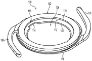
FIG. 2 is a perspective view of the base of a modular IOL according to the present disclosure;
FIG. 3 is a perspective view of the lens of a modular IOL according to the present disclosure;
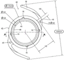
4A-4D are various views of an alternative base;
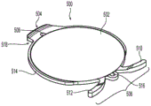
FIGS. 5A-5E are various views of an alternative lens;
6A-6D are top views of various iterations of a replacement lens;
FIG. 7 is a perspective view of a pinhole lens according to the present disclosure;
8A-8D are various views of an alternative pinhole component according to the present disclosure;
FIG. 9 is a top view of a base having drug delivery capabilities according to the present disclosure;
10A-10C are various views of an alternative base having drug delivery capabilities according to the present disclosure;
FIG. 11 is a flow chart illustrating an example process for using a modular IOL;
12A-12E illustrate an exemplary technique for implanting a modular IOL;
13A and 13B illustrate an embodiment of a probe for use with a modular IOL according to the present disclosure; and
figures 14A and 14B illustrate an embodiment of a forceps for use with a modular IOL according to the present disclosure.
Detailed Description
Referring to fig. 1, a human eye 10 is shown in cross-section. Eye 10 is depicted as an organ that reacts to light for a variety of purposes. The eye produces vision as a conscious sense organ. The rods and cones in the retina 24 produce conscious light perception and vision, including color discrimination and depth perception. In addition, the non-imaging light-sensitive ganglion cells of the human eye in the retina 24 receive light signals that affect pupil size adjustment, the regulation and suppression of the hormone melatonin, and the cyclic variation of the biological clock.
The eye 10 is not a strict sphere; but rather a fused two-piece unit. A smaller anterior unit, called the cornea 12, which bends more, is connected to a larger unit, called the sclera 14. The radius of the corneal section 12 is typically about 8mm (0.3 inch). The sclera 14 comprises the remaining five sixths; the radius is typically about 12 mm. The cornea 12 and sclera 14 are connected by a ring known as the limbus. Since the cornea 12 is transparent, the iris 16, the color of the eye and its black center, the pupil, can be seen, instead of the cornea 12. In order to see inside the eye 10, an ophthalmoscope is required, since the light rays are not reflected out. The fundus (the region opposite the pupil) containing the macula 28 shows a characteristic pale optic disc (papilla) through which blood vessels entering the eye pass, while the optic nerve fibers 18 exit the eyeball.
Thus, the eye 10 is constructed of three layers of film that wrap around three transparent structures. The outermost layer consists of the cornea 12 and sclera 14. The middle layer is composed of the choroid 20, ciliary body 22, and iris 16. The innermost layer is the retina 24, which circulates from the blood vessels of the choroid 20 and the retinal blood vessels that are visible in the ophthalmoscope. Contained within these membranes are aqueous humor, vitreous body 26 and flexible lens 30. Aqueous humor is a transparent fluid contained in two areas: the anterior chamber between the cornea 12 and iris 16 and the exposed area of the lens 30; and the posterior chamber between the iris 16 and the lens 30. The lens 30 is suspended to the ciliary body 22 by zonules 32 (zonules fraxini) formed of thin, transparent fibers. The vitreous body 26 is a transparent gel much larger than the aqueous humor.
The lens has three main components: lens capsule, lens epithelium, and lens fibers. The lens capsule forms the outermost layer of the lens, while the lens fibers form the majority of the interior of the lens. Lens epithelial cells located between the lens capsule and the outermost layer of lens fibers are predominantly present on the anterior side of the lens, but extend posteriorly to just beyond the equator.
The lens capsule is a smooth, transparent, basement membrane that completely surrounds the lens. The balloon is elastic and consists of collagen. Collagen is synthesized by lens epithelial cells, and its main components are type IV collagen and sulfated glycosaminoglycans (GAGs). The capsule is very elastic and thus gives the lens a more spheroidal shape when not under tension by the zonular fibers connecting the lens capsule to the ciliary body 22. The thickness of the bladder varies between about 2-28 microns, being thickest near the equator and thinnest near the posterior. The anterior curvature of the lens capsule is greater than the posterior curvature of the lens.
IOLs may be used to treat various diseases and conditions of lens 30. By way of example, and not necessarily by way of limitation, modular IOLs according to embodiments of the present disclosure may be used to treat cataract, large optical errors in near, far and astigmatic eyes, phakic ectopy, aphakic, pseudocrystalline, and nuclear sclerosis. However, for purposes of description, modular IOL embodiments of the present disclosure are described with reference to cataracts.
The following detailed description illustrates various embodiments of a modular IOL system including primary and secondary intraocular members (i.e., an intraocular base configured to releasably receive an intraocular optic). Features described with reference to any one embodiment may be applied to and incorporated into other embodiments.
Referring to fig. 2 and 3, base 100 and lens 200, when assembled, form an embodiment of a modular IOL. A general description of base 100 and lens 200 follows, further detailed description being provided in U.S. patent application No. 14/828,083, which is hereby incorporated by reference in its entirety.
With particular reference to fig. 2, the base 100 portion of the modular IOL includes an annular ring 102 defining a central bore 104. A pair of haptics 106 extend radially outward from the annular ring 102. Annular ring 102 includes a lower edge 108, an upper edge 110, and inwardly facing sidewalls to define an inwardly facing recess 112 into which lens 200 may be inserted to form a modular IOL.
The lower edge 108 of the base 100 may include one or more vent cuts 114 that aid in the removal of viscoelastic during surgery. The upper edge 110 may include one or more notches 116 to provide access to a probe (e.g., a Sinskey hook) during surgery, which may make it easier to manipulate the base 100. The base 100 may include an outer edge 118 extending around the periphery of the annular ring 102 to help reduce cell proliferation on the lens 200.
With particular reference to fig. 3, the lens 200 of the modular IOL includes an optic portion 202 and one or more tabs 204 and 206. As shown, the tab 204 is fixed, while the tab 206 may be actuated. The securing tab 204 may include a through hole 208 such that a probe 450 (e.g., a Sinskey hook) or similar device may be used to engage the hole 208 and manipulate the tab 204. Actuatable tab 206 is actuatable between a compressed position for delivery into aperture 104 of base 100 and an uncompressed extended position (as shown) for deployment into recess 112 of base 100, thereby forming an interlocking connection between base 100 and lens 200. It is also contemplated that the actuatable tab 206 can be inserted into the recess 112 and can be actuated between a compressed position (to facilitate insertion of the fixation tab 104 into the recess 112) and an uncompressed extended position (to further insert the fixation tab 104 into the recess 112) to form an interlocking connection between the base 100 and the lens 200.
The actuatable tab 206 may include two members 210 and 212, each member having one end connected to a peripheral edge 214 surrounding the optic 202 and the other end free, thereby forming two cantilever springs. The edge 214 may have an outer diameter that is greater than the inner diameter of the posterior edge 108 of the base 100 such that the lens 200 does not fall into the opening 104 of the base 100 and such that the lens 200 is circumferentially supported about its periphery by the posterior edge 108 of the base 100. A notch 216 may be formed in the peripheral edge 214 between the two members 210 and 212 to increase hinge-like flexibility. Notches 218 may be provided in the securing tabs 204 to provide access for a probe (e.g., a Sinskey hook) or similar device to manipulate the securing tabs 204 into the recesses 112 in the base 100. The free ends of members 210 and 212 may extend in opposite directions. It is also contemplated that one or more of members 210 and 212 may be curved to facilitate bending. For example, the radially outer surfaces of members 210 and 212 may be convex, while the radially inner surfaces of members 210 and 212 may be concave.
In general, when the base 100 and lens 200 are assembled together, these features can be configured such that the midplane of the optic 202 is parallel to the midplane of the base 100, while the central (anterior-posterior) axis of the optic 202 is coincident and collinear with the central (anterior-posterior) axis of the base 100. Assuming the anatomical symmetry of the natural lens capsule and the centering of the base 100 in the lens capsule, this configuration substantially aligns the central axis of the optic 202 with the central (anterior-posterior) axis of the capsular bag, thereby centering the optic 202. However, there may be cases where the visual (foveal) axis is not aligned with the anatomy (pupillary axis), where the difference is called the kappa angle. In such cases, it may be desirable to offset the central axis of the optic 200 relative to the base 100, thereby providing decentration. This can be achieved, for example, by: tabs 204 and 206, recesses 112, and/or haptics 106 are configured such that the central (anterior-posterior) axis of optic 202 is laterally (relative to the nose or temple) offset relative to the central (anterior-posterior) axis of base 200. By way of example and not limitation, the sidewalls defining the recess 112 in the base may be offset relative to the haptics 106 such that the central axis of the optic 202 is offset. Different offsets may be provided, for example 0.5mm to 2.0mm in increments of.5 mm. Angular orientation marks may be provided on the base 100 and lens 200 to indicate the direction of the offset (relative to the nose or temple). Similarly, the midplane of the assembled base 100 and optic 200 may be tilted relative to the equatorial plane of the natural capsular bag. To compensate for this tilt, tabs 204 and 206, recesses 112, and/or haptics 106 may be configured such that the midplane of optic 202 is inversely tilted, for example.
As will be described in more detail later, for example, the lens 200 can be rolled about axis 220 or axis 222 for delivery via an injector. Axes 220 and 222 substantially bisect lens 200. The axis 220 passes through the center of the optic 202 and through the centers of the two tabs 204 and 206. The axis 222 passes through the center of the optic 202 between the two tabs 204 and 206, such that the diametrically opposed tabs 204 and 206 are located on either side of the axis 222.
The base 100 and lens 200, including the alternative embodiments described herein, may be formed by cryogenic processing and polishing of hydrophobic acrylic materials. Alternatively, the base 100 may be manufactured by forming two (front and rear) components and bonding them together. For example, the two components may be low temperature processed hydrophilic acrylic joined together by a uv curable adhesive. Alternatively, the two components may be formed of different materials that are bonded together. For example, the anterior component may be formed of a hydrophilic acrylic that does not adhere to ocular tissue, while the posterior component may be formed of a hydrophobic acrylic that adheres to ocular tissue.
As another alternative, the base 100 may be manufactured by low temperature machining a first component and overmolding a second component. The first component may include geometric features that become interlocked when overmolded, thereby reducing the need to use an adhesive to connect the components. For example, the base 100 may be manufactured by: low temperature processing of hydrophilic acrylic to form a back component, and overmolding of a front component of moldable material such as silicone.
While hydrophobic acrylic makes the base 100 and lens 200 visible using Optical Coherence Tomography (OCT), it may be desirable to include materials that enhance OCT visualization. Example "OCT-friendly" materials include, but are not limited to, polyvinyl chloride, glycol-modified poly (ethylene terephthalate) (PET-G), poly (methyl methacrylate) (PMMA), and polyphenylsulfones, such as those sold under the trade name RADELTM, as described in U.S. patent application publication 2013/0296694 to Ehlers et al, which is incorporated herein by reference. Such OCT friendly materials may be applied to or incorporated into a portion of the base 100 or lens 200. As an example, concentric rings of OCT friendly material may be applied to each of the lower and upper edges 108/110. The rings may have different diameters to help detect tilting of the base. Also by way of example, an OCT friendly material may be applied to tab 204/206 of lens 200. This can help determine whether the base 100 and lens 200 are properly assembled in the eye. Dots of OCT friendly material can be applied to portions of the base 100 that are aligned with corresponding dots of OCT friendly material on the optics 200 to indicate correct assembly in the eye.
As an alternative to a solid material, the base 100 and lens 200 may be made of a hollow material that can then be inflated in the eye. In this arrangement, the base 100 and lens 200 may be made of, for example, molded silicone and inflated with a liquid such as saline, silicone gel, or the like using an injector and a needle. After implantation in the eye, the needle may pierce the walls of the base 100 and the lens 200 to inflate the components. The material may seal itself after the needle is removed. As an alternative to a hollow material, the base 100 and lens 200 may be formed from a sponge-like material (e.g., a silicone hydrogel that expands when hydrated). Both methods allow the size of the corneal incision to be smaller because the base 100 and lens 200 are delivered in an uninflated or unexpanded state and then inflated or expanded once inside the eye.
Referring to fig. 4A-4D, an alternative base 400 is shown. Fig. 4A is a perspective view, fig. 4B is a top view, fig. 4C is a sectional view taken along line a-a in fig. 4B, and fig. 4D is a detailed sectional view of circle C in fig. 4C. The dimensions (mm) are given as examples and are not necessarily limiting. The alternative base 400 is similar to the base 100 described with reference to fig. 2, except as described below.
The alternative base 400 includes an annular ring 402 defining a central aperture 404. A pair of haptics 106 extend radially outward from annular ring 402. Annular ring 402 includes a lower edge 408, an upper edge 410, and an inward facing recess 412 into which lens 200 may be inserted to form a modular IOL. As will become apparent from the description with reference to fig. 4A-4D, the recess 412 of the base 400 is sized and configured differently than the recess 112 of the base 100.
The upper edge 410 of the annular ring 402 may include one or more notches 116 to provide intraoperative access for a probe (e.g., a Sinskey hook), which allows for easier manipulation of the base 400. Haptic 106 may include a hole 416 adjacent annular ring 402 for the same purpose as notch 116. A pair of square edges 417 may extend around the posterior periphery of annular ring 402 to help reduce cell proliferation (posterior capsule opacification or PCO) on lens 200.
With particular reference to fig. 4D, the deep portion of the pocket 412 may have a square profile defined by a horizontal rear surface 418, a horizontal front surface 420, and vertical side or outer surfaces 422. The recess may also include a flared forward surface 426 extending radially inward and forward outward from the horizontal forward surface 420 and a flared rearward surface 428 extending radially inward and rearward outward from the horizontal rearward surface 418. The inner diameter of trailing edge 408 may be less than the inner diameter of leading edge 410. With this arrangement, lens 200 can be placed through the circular opening defined by anterior edge 410 to fall or rest on the posterior edge, and flared anterior wall 426 along with flared posterior wall 428 can act as a funnel to guide tabs 204 and 206 of lens 200 into the deep portion of recess 412. When fully seated in recess 412, horizontal posterior wall 418, horizontal anterior wall 420, and vertical side walls 422 form a keyed geometry with corresponding horizontal and vertical sides of tabs 204 and 206 to limit movement of lens 200 relative to base 400 in the anterior, posterior, and radial directions.
Referring to fig. 5A-5E, an alternative lens 500 is shown. Fig. 5A is a perspective view, fig. 5B is a top view, fig. 5C is a sectional view taken along line AA in fig. 5B, fig. 5D is a detailed sectional view of circle B in fig. 5C, and fig. 5E is a detailed top view of circle C in fig. 5B. The dimensions (mm) are given as examples and are not necessarily limiting. The replacement lens 500 is similar to the lens 200 described with reference to fig. 3, except as described below.
As seen in fig. 5C, the anterior and posterior sides of optic 502 may have convex radii corresponding to the desired optical power (diopters) of the optic. As shown, the securing tab 504 and the spring tabs 510 and 512 can have flared cross sections. More specifically, and as better seen in the detailed view shown in fig. 5D, the securing tabs 504 extend radially outward from the optic 502 from a thinner inner portion 504B to a flared thicker outer portion 504A. The aperture 508 may extend through the thinner inner portion 504B. The outermost profile of thicker portion 504A has a square profile with anterior horizontal sides, posterior horizontal sides, and lateral or outer vertical sides that are keyed to recesses 412 as previously described to minimize anterior-posterior and radial/lateral movement of lens 500 relative to base 400. The thicker portion 504A also improves engagement with the plunger of the injector, thereby mitigating clogging of the lens 500 in the injector. Thinner portion 504B also provides a forward and rearward offset from the surface defining recess 412 of base 400, thereby mitigating adhesion between lens 500 and base 400. As shown, the same splay configuration and associated advantages also apply to each spring tab 510 and 512.
Commercially available IOLs typically have a equator diameter (excluding haptics) of about 6mm, an anterior-posterior thickness of about 0.2mm at the 6mm diameter, and an anterior-posterior thickness of about 0.7mm at the center, thereby providing a total volume of about 12mm 3. Lens 500 is of similar size but base 400 adds a much larger volume. Base 400 may have a equator diameter of about 7.8mm (excluding haptics), an anterior-posterior thickness of about 1mm, providing a total volume of about 26 cubic millimeters when the lens is seated in the base 13.4mm3 base, 12.5mm3 optic. Thus, the combined size of the base 400 and lens 500 is much larger in volume than a commercially available conventional IOL. This relatively large volume is intended to fill the capsular bag more like a natural lens, increasing the stability of the base 400 and lens 500 and reducing post-operative migration due to the capsular bag collapsing around the base 400. By comparison, a typical natural lens has a equator diameter of about 10.4mm, an anterior-posterior dimension of about 4.0mm, and a corresponding volume of about 180mm 3. Due to anatomical variations, the volume of the natural lens may range from 130mm3 to 250mm 3. Thus, after the natural lens is removed, the base 400 plus lens 500 consumes more than 10% (about 20% to 10.4%) of the capsular bag volume, whereas conventional IOLs consume less than or equal to 10% (about 10% to 5%) of the capsular bag volume. In other words, the base 400 plus lens 500 consumes about twice the volume of the capsular bag as a conventional IOL.
Referring to fig. 6A-6D, various iterations of lens 500 are shown in schematic top views. In fig. 6A, lens 500A includes actuatable tab 506A with spring tabs 510A and 512A that include holes 520 for manipulation by a probe or similar device. The spring tabs 510A and 512A are relatively longer than the embodiment described with reference to fig. 5A-5E and extend in a radially outward direction from the optic 502 with the respective ends extending toward each other. This allows the actuatable tab 506A to be easily manipulated so that the fixed tab 504 can be inserted into the recess 412 of the base 400, and then the spring tabs 510A and 512B can be individually manipulated and tucked into the recess 412 using a probe placed in the hole 520. Holes 520 may be positioned on the spring tabs 510A and 512A and sized so that they are partially visible when positioned in the recess 412. In other words, if the hole 520 is fully visible, the spring tabs 510A and 512A are located forward of the front edge 410 of the base 400, if the hole 520 is not visible, the spring tabs 510A and 512A are located rearward of the rear edge 408 of the base 400, and if the hole 520 is partially visible (e.g., half visible), the spring tabs 510A and 512A are properly located in the recess 412 of the base 400. Because the ends of the spring tabs 510A and 512A are closer together than the ends of the arms 510 and 512 of the lens 500, a smaller field of vision is required to confirm that the actuatable tab 506A is located in the recess 412 of the base 400 when viewed under a microscope during surgery. Fig. 6B shows a similar lens 500B, but with shorter spring tabs 510B and 512B to provide greater resilience and stability in the recess 412 of the base 400.
In fig. 6C, actuatable tabs 506C include spring tabs 510C and 512C that extend in a radially outward direction from optic 502, with respective ends extending away from each other. By extending away from each other, spring tabs 510C and 512C provide a wider base in contact with recess 412 of base 400, thereby mitigating tipping of lens 500C within the base. Fig. 6D shows a similar lens 500D, but with spring tabs 510D and 512D having wider attachments to optics 502 to provide greater resilience and stability in the recess 412 of the base 400.
Referring to fig. 7, the optic portion 202 of lens 200 may include an opaque ring 230 defining a small central aperture 232 (pinhole) of 1.0-2.0mm to allow only focused light rays to enter the eye to increase the depth of focus. Opaque ring 230 may include a black mask or other surface treatment applied to the surface of optic 202 to partially or completely block visible light. The surface treatment may be applied to the optic 202 prior to implantation (i.e., at the time of manufacture) or may be applied post-operatively (i.e., after implantation) to customize the characteristics (e.g., size and location) of the aperture 232 to the needs of the patient. The surface treatment may include laser etching or frosting of the surface of the optic 202 to define or modify the opaque ring 230. Alternatively, the surface treatment may include selective activation or deactivation of chromophores on or embedded in the optic 202 to change its color or contrast (brighter or darker) and thus define or modify the aperture 232. As shown, the aperture 232 may be centered on the optic 202, or may be off-center, such that the lateral position of the aperture 232 may be adjusted relative to the visual axis by rotating the lens 200 relative to the base 100.
Alternatively, as shown in fig. 8A-8D, an opaque ring may include a third (separate) part 800 having a pinhole. Fig. 8A is a perspective view, fig. 8B is a sectional view taken along line a-a in fig. 8A, fig. 8C is a side view, and fig. 8D is a bottom view of the pinhole part 800. The pinhole component 800 may include an opaque front ring 830 defining a small central aperture 832 (pinhole) of 1.0-2.0mm to allow only focused light rays to enter the eye to increase the depth of focus. The securing tabs 804 may extend radially outward from the rear mount ring 820. Similarly, actuatable tabs 806, including spring members 810 and 812, can extend radially outward from the support ring 820 in another diametrical direction. Posterior holder ring 820 may have a height slightly higher than the thickness of lens 200 such that tabs 804 and 806 align with recesses 112 on base 100 when pinhole component 800 rests on the anterior side of lens 200. This configuration allows pinhole component 800 to be positioned on lens 200 with both lens 200 and pinhole component 800 attached to base 100. Pinhole member 800 may be attached to base 100 such that tabs 804 and 806 of pinhole member 800 are positioned offset (e.g., 90 degrees) relative to tabs 204 and 206 of lens 200. In other words, tabs 804 and 806 of pinhole component 800 utilize the portion of recess 112 of base 100 not occupied by tabs 204 and 206 of lens 200. Alternatively, a similar configuration may be used for the third component comprising a toric lens, a multifocal lens, a retractable lens, and the like.
Alternatively, as shown in fig. 9, the medication may be incorporated into or carried by the base 100. In contrast to the lens 200, the use of the base 100 as a drug carrier has many advantages. For example, it avoids any interference that one or more drugs may have with the optical performance of the lens 200. Moreover, since the base 100 does not require inversion as part of the manufacturing process (as required for the lens 200), the medication carried by the base 100 is not potentially compromised. The drug may be incorporated into the base 100 by: attaching one or more separate drug carriers to the base 100, having the material of the base 100 act as a carrier for the drug (e.g., like a sponge), incorporating one or more drug eluting materials into the base 100, or incorporating one or more refillable reservoirs carrying the drug into the base 100. For example, one or more portions of the base 100 may carry one or more drugs, and the portions may be separated from each other to avoid, for example, interactions between different drugs. The portion or portions of the base 100 carrying the drug may be selectively activated by light or thermal energy (e.g., laser, ultraviolet light, etc.) to release the stored drug or drugs in their entirety at one time or in multiple portions over time.
Examples of clinical indications for such drugs include wet or dry macular degeneration, open or closed angle glaucoma, uveitis, posterior capsule opacification, post-operative management after cataract surgery, and the like. Examples of drugs that may be used for wet macular degeneration include aflibercept, bevacizumab, pegaptanib, ranibizumab, steroids, and aptamers. Examples of drugs that can be used for dry macular degeneration include complement factors, antioxidants, and anti-inflammatory agents. Examples of drugs that may be used in open angle glaucoma include brimonidine, latanoprost, timolol, pilocarpine, brinzolamide and others belonging to the general class of beta blockers, alpha agonists, ROCK inhibitors, adenosine receptor agonists, carbonic anhydrase inhibitors, adrenergic and cholinergic receptor activators and prostaglandin analogs. Examples of drugs that may be used for uveitis include methotrexate, antibodies, dexamethasone, triamcinolone, and other steroid agents. Examples of drugs that may be used for posterior capsule opacification include antiproliferative agents, antimitotic agents, anti-inflammatory agents, and other drugs that inhibit the spread of lens epithelial cells. Examples of drugs that can be used for post-operative management after cataract surgery include antibiotics, such as fluoroquinolones; non-steroidal agents, such as ketorolac; and steroids, such as prednisolone. Other drugs that may be used to treat various ocular diseases and conditions include: anti-fibrotic agents, anti-inflammatory agents, immunosuppressive agents, antineoplastic agents, migration inhibitors, antiproliferative agents, rapamycin, triamcinolone acetonide, everolimus, tacrolimus, paclitaxel, actinomycin, azathioprine, dexamethasone, cyclosporine, bevacizumab, anti-VEGF agents, anti-IL-1 agents, canamab, anti-IL-2 agents, viral vectors, beta receptor blockers, alpha agonists, muscarinic agents, steroids, antibiotics, non-steroidal anti-inflammatory agents, prostaglandin analogs, ROCK inhibitors, nitric oxide, endothelin, matrix metalloproteinase inhibitors, CNPA, corticosteroids, and antibody-based immunosuppressive agents. These drugs may be used alone or in combination depending on the particular clinical indication of the patient.
In addition, a portion or portions of the base 100 carrying one or more drugs may face in a particular direction or directions, while other directions are masked or blocked to increase the concentration of the drug on a particular portion of the lens capsule. For example, posterior ocular structures may be the focus of drug delivery (e.g., to reduce macular degeneration), and/or anterior ocular structures may be the focus of drug delivery (e.g., delivery of glaucoma drugs near the angle, delivery of uveitis drugs, or post-operative management after cataract surgery).
By way of example, fig. 9 shows a top (front) view of a base 100 incorporating one or more drug carriers 90. As shown, the drug carriers 90 are spaced around the circumference of the front side of the body of the base 100. The drug carrier 90 may include a refillable reservoir (e.g., a silicone container), an eluting porous material (e.g., a biocompatible sponge), a biodegradable or bioerodible material (e.g., PLGA), or the like. The reservoir may also be designed to expose the drug to an aqueous environment by laser, ultraviolet light, RF signal, magnetic manipulation, or other means of remotely removing a diffusion barrier. For example, the carrier 90 may be disposed on a surface of the base 100, or may be embedded therein. To focus the delivery of the drug to a particular area of the eye, the carrier 90 may be exposed on one side (e.g., the anterior side as shown) while the material of the base 100 covers the other side.
An alternative medication carrying base 100 is shown in fig. 10A-10C. Fig. 10A is a perspective view, fig. 10B is a sectional view taken along line B-B in fig. 10A, and fig. 10C is a sectional view taken along line C-C in fig. 10A. As shown in fig. 10B and 10C, the base 100 may include an internal channel 96 extending around the circumference of an annular ring 102. The internal passage 96 is in fluid communication with the exterior of the base 100 via a series of ports 92, which may be equally distributed around the front side of the annular ring 102. A ring of material 94 may be disposed in the channel 96. The ring of material 94 may have a dehydrated volume that is less than the volume of the channel 96, and a hydrated volume that is greater than its dehydrated volume up to the volume of the channel 96. The ring of material 94 may comprise, for example, a high Equilibrium Water Content (EWC) silicone hydrogel or other similar hydratable or sponge-like material. In use, the base 100 with the dehydrated ring 94 may be soaked in a fluid, for example, containing a desired drug or drugs (e.g., steroids and NSAIDs), prior to implantation. The port 92 will allow the drug-laden fluid to flow to the dewatering ring 94, which will cause the dewatering ring 94 to increase in volume (expand) as hydration occurs with the drug-laden fluid. The hydration ring 94 may then occupy the entire volume of the channel 96. When the base 100 is implanted, the aqueous humor of the eye contacts the ring of hydrated material 96 adjacent the ostium 92, rather than submerging the entire ring 94 in the channel 96. Thus, the elution of drug from the ring 94 into the eye can be controlled by the number and size of the ports 92, which can be selected to achieve a desired elution rate for a given drug or combination of drugs.
In general, a modular IOL including an assembled base 100 and lens 200 (including the alternative embodiments described herein) allows for the adjustment or replacement of lens 200 while leaving base 100 in place, either intra-or post-operatively. Examples of situations where this is desirable include, but are not limited to: replacing the lens 200 to correct the less than ideal refractive outcome detected during surgery; replacing the lens 200 to correct the post-operative detected less than ideal refractive outcome (residual refractive error); rotationally adjusting the lens 200 relative to the base 100 to fine tune the toric correction; laterally adjusting the lens 200 relative to the base 100 to align the optics with the true optical axis (which may not be the center of the capsular bag); and replacing the lens 200 to address the changing optical needs or desires of the patient over a longer period of time. Examples of the latter case include, but are not limited to: adult IOL patients or pediatric IOL patients whose primary optical correction needs to change with developmental maturity; patients who wish to upgrade from monofocal IOLs to advanced IOLs (toric, multifocal, accommodating or other future lens technologies); patients who are not satisfied with advanced IOLs and who want to degrade to monofocal IOLs; and patients who develop medical conditions to which IOLs or certain types of IOLs are contraindicated.
Figure 11 shows an example of a process for implanting a modular IOL. In this example, intraoperative measurements can be made to select a desired lens 200 and/or to determine if intraoperative adjustments or replacement are required. An IOL implantation procedure, such as cataract surgery, may be initiated 310 in accordance with conventional practice. The natural lens capsule can then be prepared 312 to receive the modular IOL using conventional steps such as making a corneal entry incision, forming a capsulorhexis in the anterior capsular bag, and removing the cataractous lens by phacoemulsification or other means. The base 100 is then placed 314 in the pocket. At this point, 316 intraoperative measurements may be performed to determine the position of the base 100 relative to the anatomical structure. This information may be used, for example, to adjust the position of the base 100 and/or to help select a desired power of the optic 202 of the lens 200.
As a specific example, Optical Coherence Tomography (OCT) can be used to measure the Effective Base Position (EBP) along the visual axis, which will determine the Effective Lens Position (ELP) once the lens 200 is attached to the base 100. Because ELP affects refractive outcome, EBP information can be used to select a lens 200 with the appropriate refractive power. This may reduce residual refractive error, particularly because the post-operative EBP is relatively stable. OCT can also be used to detect decentration and tilt of the base 100 so that it can be adjusted intra-operatively. As described elsewhere herein, the base 100 can contain materials that enhance OCT visualization.
Optionally, a temporary lens 200 can be placed in the eye and attached to the base 100 prior to OCT measurements. This may be helpful if the iris is small, making OCT visualization of the base 100 challenging. The temporary lens 200 can be very thin (e.g., 0-2 diopters) so that it can be easily removed after OCT measurements are completed. As an alternative to a thin temporary lens, a thin disk of OCT reflective material may be placed on or attached to the base 100 prior to OCT measurements, which are then removed.
The lens 200 is then placed in the 320 capsular bag. The base 100 and lens 200 are then assembled 322 together as described in more detail below. At this point, intraoperative measurements 324 can be performed to determine whether the base 100 and lens 200 are properly assembled, to determine the position of the assembled base 100 and lens 200 relative to the anatomy, and/or to determine whether the optical correction is satisfactory 326.
For example, OCT can be used to determine if tabs 204 and 206 of lens 200 are in recess 112 of the base, and steps can be taken to properly assemble lens 200 and base 100, if desired. Additionally or alternatively, OCT can be used to measure ELP, decentration, or tilt, and steps can be taken to adjust the position of the lens 200 and/or the base 100, if desired. Additionally or alternatively, the optical result may be measured using wavefront aberration measurements. If it is determined 326 that the optical result is satisfactory, the process may be completed 328 according to conventional practice. If it is determined 326 that the optical result is not satisfactory, a determination 330 is made as to whether making an adjustment (e.g., rotation, lateral offset, etc.) to lens 200 and/or base 100 would result in a satisfactory optical result. If so, an adjustment 332 is made and the process is completed 328. If not, the lens 200 is detached 334 from the base 100, removed 336 from the eye, and a new lens 200 is selected 318 and implanted 328 in accordance with the same steps 320-328.
Figures 12A-12D illustrate a technique for implanting a modular IOL 100/200. As shown in fig. 12A, a modular IOL may be implanted by: the base 100 is first delivered into the capsular bag in a rolled configuration using an injector 300 (also known as an inserter or delivery tube) inserted through the corneal incision 13, through the capsulorhexis 36, and into the capsular bag 34. A conventional injector 300 (also referred to as an inserter) may be used to deliver the base 100 and lens 200. Examples of suitable injectors are described in U.S. patent No. 5,123,905 to Kelman, U.S. patent No. 4,681,102 to Bartell, U.S. patent No. 5,304,182 to Rheinish, and U.S. patent No. 5,944,725 to cic.
As shown in fig. 12B, the base 100 may be ejected from the injector and allowed to deploy. With gentle manipulation, haptics 106 of base 100 engage the medial equator of the lens capsule 34 and center the aperture 104 of base 100 with respect to the capsulorhexis 36.
As shown in fig. 12C-12D, lens 200 can be attached to base 100 by first inserting actuatable tabs 206 into recesses 112. With respect to fig. 12C, it should be understood that the actuatable tab can have the features of the actuatable tab 206 of fig. 3. The actuatable tab 206 may be manipulated into the recess 112 using the probe 450. Alternatively, actuatable tabs 206 may be manipulated into recesses 112 during an injection step using injector 300 to manipulate lens 200. In this alternative, the lens 200 is partially ejected from the injector 300 and the actuatable tab 206 is placed in the recess 112 of the base 100 while the fixed tab 204 remains in the injector 300. Once the actuatable tabs 206 are located in the recesses 112, the lens 200 may be fully ejected from the injector 300.
Lateral force may then be applied to compress the actuatable tabs 206 by using the probe 450 or similar device inserted into the holes 208 of the fixed tabs 204, thereby allowing the lens 200 to be advanced into the hole 104 of the base 100 such that the lens 200 and base 100 are coplanar. The compressive force can then be released from the actuatable tabs 206, thereby causing the securing tabs 204 to slide into the recesses 112 of the base 100, thereby connecting the lens 200 to the base 100. The reverse procedure may be taken to detach the lens 200 from the base 100.
Alternatively, the actuatable tab 206 may be compressed using the injector 300. In this alternative, the lens 200 is partially ejected from the injector 300 such that the actuatable tab 206 is placed in the recess 112 of the base 100 while the fixed tab 204 remains in the injector 300. Pushing the lens 200 with the injector 300 compresses the actuatable tabs 206 in the recess 112. When the actuatable tab 206 is compressed, a probe can be inserted into the second corneal incision to apply a reactive force to the base 100. Injector 300 may then be used to co-planarly position lens 200 with base 100 such that fixation tabs 204 are aligned with recesses 112. Lens 200 can then be fully ejected from injector 300, releasing the compression of actuatable tabs 206 and allowing securing tabs 204 to move into recesses 112 of base 100.
Prior to delivery of the lens 200, the lens 200 may be folded or rolled and placed in the injector 300 for delivery as described above. As described with reference to fig. 3, for example, lens 200 may be rolled about axis 220 or axis 222 (which substantially bisects lens 200). The lens 200 can be rolled in either a forward or rearward direction. In one example, lens 200 may be folded or rolled from one end to the other in a manner similar to rolling a poster. Alternatively, in another example, the opposing ends of lens 200 may be folded or rolled inward toward axis 220 or axis 222.
Another technique that may obviate the need to compress the actuatable tabs 206 to connect the lens 200 to the base 100 involves applying a torque to the fixed tabs 204. Referring to fig. 12E, lens 200 can be ejected from injector 300 and positioned on the anterior side of base 100. The actuatable tab 206 is placed in the recess 112 of the base. The probe 450 is placed in the hole 208 in the securing tab 204. Torque is applied to the securing tabs 204 by rotating the probe 450, causing the securing tabs 204 to flex back and radially inward, and the optic 202 to bend forward. The securing tabs 204 may then be aligned with the recesses 112 in the base 100 and the torque released, causing the securing tabs 204 to extend radially outward to their rest position in the recesses 112 of the base 100.
Referring to fig. 13A and 13B, an embodiment of a probe 450 is schematically illustrated. The probe 450 may resemble the Sinskey hook currently commonly used for cataract surgery, with some variations. As shown in fig. 13A, the probe 450 includes a shaft 460 and a distal portion 470. The proximal handle portion of the probe 450 is not shown, but may be a standard Sinskey handle. The distal portion 470, shown in detail in fig. 13B, includes a distal shaft 472, an elbow 474, an elbow extension 476, an insertion tip 478, and a collar 480. Insertion tip 478 is sized to fit into aperture 208 in lens 200 for manipulation thereof. Collar 480 is sized larger than aperture 208 so that tip 478 does not penetrate into aperture 208, thereby preventing probe 450 from sticking to lens 200.
Referring to fig. 14A and 14B, an embodiment of a folding forceps 600 is shown. Folding forceps 600 include a pair of leaf spring arms 602, each having a gripping portion 604 and an angled distal portion 606. Arm 602 is attached proximally at junction 608. The distal portion 606 includes a tip 610 associated with each arm. The arms 602 are biased as shown, but can be squeezed to separate the distal tip 610, limited by the stop 612. With this arrangement, arms 602 can be squeezed and tips 610 can be inserted into diametrically opposed holes or recesses in the lens, such as hole 208 and recess 216 of lens 200 or holes 516 and 518 of lens 500. When arms 602 are released, tips 610 move closer together, causing lens 200 or 500 to arch and corresponding tabs 204/206 or 504/506 to move closer together. As the tabs 204/206 or 504/506 come closer together, they can be inserted into the recess 112/412 of the base 100/400 without the need to compress the actuatable tab 206/506 of the lens 200/500.
The foregoing discussion of the disclosure has been presented for purposes of illustration and description. The foregoing is not intended to limit the disclosure to the form or forms disclosed herein. While the present disclosure includes a description of one or more embodiments and certain variations and modifications, other variations and modifications are within the scope of the disclosure, e.g., as may be within the skill and knowledge of those in the art, after understanding the present disclosure. It is intended to obtain rights which include alternative embodiments to the extent permitted, including alternate, interchangeable and/or equivalent structures, functions, ranges or steps to those claimed, whether or not such alternate, interchangeable and/or equivalent structures, functions, ranges or steps are disclosed herein, and without intending to publicly dedicate any patentable subject matter.
Claims (24)
1. A modular intraocular lens system comprising:
a base comprising an annular ring, the annular ring comprising:
an upper edge surrounding a front opening, wherein the upper edge has a front surface and a rear surface,
a lower edge surrounding a rear opening, wherein the lower edge has a front surface and a rear surface, and wherein a horizontal portion of the front surface of the lower edge extends parallel to a horizontal portion of the rear surface of the lower edge,
a wall extending between the upper edge and the lower edge, wherein the wall has a radially inner surface, and wherein an annular portion of at least one of the upper edge and the lower edge is inclined relative to the wall,
a channel extending through the base from the front opening to the rear opening, an
A recess surrounding the channel, wherein the recess is defined by a horizontal front surface located at the rear surface of the upper rim, a horizontal rear surface located at the front surface of the lower rim, and the radially inner surface of the wall; and
a lens configured for insertion into and removal from the base, the lens comprising:
an optical device, and
at least one tab protruding from the optic, wherein the tab is received by the recess of the base and the optic extends through the channel of the base when the lens is inserted into the base.
2. The modular intraocular lens system of claim 1, wherein a thickness of the upper edge decreases as the upper edge approaches the anterior opening.
3. The modular intraocular lens system of claim 1, wherein the annular portion of the upper rim is inclined relative to the wall.
4. The modular intraocular lens system of claim 1, wherein the flared portion of the anterior surface of the superior edge is angled relative to the wall.
5. The modular intraocular lens system of claim 1, wherein the posterior surface of the superior edge is inclined relative to the wall.
6. The modular intraocular lens system of claim 1, wherein the flared portion of the anterior surface and the posterior surface of the superior edge have different slopes relative to the wall.
7. The modular intraocular lens system of claim 1, wherein the base has a central longitudinal axis, and wherein each of the anterior and posterior surfaces of the lower edge includes a portion extending perpendicular to the wall.
8. The modular intraocular lens system of claim 1, wherein each of the anterior and posterior surfaces of the lower edge includes a portion that is inclined relative to the wall.
9. The modular intraocular lens system of claim 1, wherein the height of the base measured in the anterior-posterior direction is 1.01 mm.
10. The modular intraocular lens system of claim 1, wherein the base is 7.78mm in diameter.
11. A modular intraocular lens system comprising:
a base comprising an annular ring, the annular ring comprising:
an upper edge surrounding a front opening,
a lower edge surrounding a rear opening,
a wall extending between the upper edge and the lower edge,
a channel extending through the base from the front opening to the rear opening, an
A recess surrounding the channel, wherein the recess is defined by the upper edge, the lower edge, and a surface of the wall; and
a lens configured for insertion into and removal from the base, the lens comprising:
an optical device, and
a tab protruding from the optic, wherein the tab is received by the recess of the base and the optic extends through the channel of the base when the lens is inserted into the base.
12. The modular intraocular lens system of claim 11, wherein the tab is a first tab, wherein the lens further comprises a second tab protruding from the optic, and wherein the first tab is stiffer than the second tab.
13. The modular intraocular lens system of claim 12, wherein the optic has an optic axis, and wherein the first tab is asymmetric about a plane bisecting the second tab and containing the optic axis.
14. The modular intraocular lens system of claim 12, wherein the first tab is asymmetric about a plane that bisects the optic and the second tab.
15. The modular intraocular lens system of claim 12, wherein the lens further comprises a hole extending therethrough, and wherein the hole is located where the first tab intersects the optic.
16. The modular intraocular lens system of claim 12, wherein the second tab comprises:
a radially inner portion protruding from a periphery of the optic; and
a radially outer portion, wherein the radially outer portion projects radially outward from the radially inner portion, and wherein the radially outer portion comprises one or more flexible arms.
17. The modular intraocular lens system of claim 16, wherein the lens further comprises a bore extending through the radially inner portion.
18. A modular intraocular lens system comprising:
a base comprising an annular ring, the annular ring comprising:
an upper edge surrounding a front opening, wherein the upper edge has a front end,
a lower edge surrounding a rear opening, wherein the lower edge has a rear end,
a wall extending between the upper edge and the lower edge, wherein the wall includes a radially inner surface, and wherein a ratio between a distance of the base between a front surface of the upper edge and a rear surface of the lower edge, measured in a front-to-rear direction, and a diameter of the base is between 0.11 and 0.14,
a channel extending through the base from the front opening to the rear opening, an
A recess surrounding the channel, wherein the recess is defined by surfaces of (a) and (b):
(a) said upper edge and said lower edge, and
(b) the radially inner surface of the wall; and
a lens configured for insertion into and removal from the base, the lens comprising:
an optical device, and
at least one tab protruding from the optic, wherein the tab is received by the recess of the base and the optic extends through the channel of the base when the lens is inserted into the base.
19. The modular intraocular lens system of claim 18, wherein the height of the base measured in the anterior-posterior direction is 1.01mm, and wherein the diameter of the base is 7.78 mm.
20. The modular intraocular lens system of claim 18, wherein each of the upper edge and the lower edge is angled relative to the wall.
21. A modular intraocular lens system comprising:
an annular base, the annular base comprising:
the plane of the middle weft line is provided with a plurality of parallel lines,
a first end section surrounding a first end opening, wherein the first end section comprises:
(a) a first surface, wherein the first surface is at a first angle relative to the equator plane, an
(b) A second surface opposite the first surface, wherein the second surface is at a second angle relative to the equator plane, and wherein the first angle and the second angle are different,
a second end section surrounding a second end opening,
a wall extending between the first end section and the second end section, wherein an annular portion of at least one of the first end section and the second end section is inclined relative to the wall,
a channel extending through the annular base from the first end opening to the second end opening, an
A recess surrounding the channel, wherein the recess is defined by the first end section, the second end section, and a surface of the wall; and
a lens configured for insertion into and removal from the annular base, the lens comprising:
an optical device, and
at least one tab protruding from the optic, wherein the tab is received by the recess of the annular base and the optic extends through the channel of the annular base when the lens is inserted into the annular base.
22. The modular intraocular lens system of claim 21, wherein the second angle is greater than the first angle.
23. The modular intraocular lens system of claim 21, wherein a thickness of the first end segment measured in a direction along the central longitudinal axis of the annular base decreases as the first end segment approaches the first end opening.
24. The modular intraocular lens system of claim 21, wherein the annular portion of each of the first end segment and the second end segment is inclined relative to the wall.
Priority Applications (1)
| Application Number | Priority Date | Filing Date | Title |
|---|---|---|---|
| CN202111087756.0A CN113730030A (en) | 2015-11-04 | 2016-11-03 | Modular intraocular lens design, tools and methods |
Applications Claiming Priority (7)
| Application Number | Priority Date | Filing Date | Title |
|---|---|---|---|
| US201562250780P | 2015-11-04 | 2015-11-04 | |
| US62/250,780 | 2015-11-04 | ||
| US201562256579P | 2015-11-17 | 2015-11-17 | |
| US62/256,579 | 2015-11-17 | ||
| US201662318272P | 2016-04-05 | 2016-04-05 | |
| US62/318,272 | 2016-04-05 | ||
| PCT/US2016/060350 WO2017079449A1 (en) | 2015-11-04 | 2016-11-03 | Modular intraocular lens designs, tools and methods |
Related Child Applications (1)
| Application Number | Title | Priority Date | Filing Date |
|---|---|---|---|
| CN202111087756.0A Division CN113730030A (en) | 2015-11-04 | 2016-11-03 | Modular intraocular lens design, tools and methods |
Publications (2)
| Publication Number | Publication Date |
|---|---|
| CN108348327A CN108348327A (en) | 2018-07-31 |
| CN108348327B true CN108348327B (en) | 2021-10-01 |
Family
ID=57281312
Family Applications (2)
| Application Number | Title | Priority Date | Filing Date |
|---|---|---|---|
| CN202111087756.0A Pending CN113730030A (en) | 2015-11-04 | 2016-11-03 | Modular intraocular lens design, tools and methods |
| CN201680064319.8A Active CN108348327B (en) | 2015-11-04 | 2016-11-03 | Modular intraocular lens design, tools and methods |
Family Applications Before (1)
| Application Number | Title | Priority Date | Filing Date |
|---|---|---|---|
| CN202111087756.0A Pending CN113730030A (en) | 2015-11-04 | 2016-11-03 | Modular intraocular lens design, tools and methods |
Country Status (7)
| Country | Link |
|---|---|
| US (2) | US11076948B2 (en) |
| EP (1) | EP3370645A1 (en) |
| JP (3) | JP6993328B2 (en) |
| CN (2) | CN113730030A (en) |
| AU (3) | AU2016349363B2 (en) |
| CA (1) | CA3002085A1 (en) |
| WO (1) | WO2017079449A1 (en) |
Families Citing this family (39)
| Publication number | Priority date | Publication date | Assignee | Title |
|---|---|---|---|---|
| CN102883682A (en) | 2010-04-27 | 2013-01-16 | 雷恩斯根公司 | Accommodating intraocular lens device |
| EP2806828B1 (en) | 2012-01-24 | 2021-07-21 | The Regents of The University of Colorado, A Body Corporate | Modular intraocular lens designs and methods |
| US8900300B1 (en) | 2012-02-22 | 2014-12-02 | Omega Ophthalmics Llc | Prosthetic capsular bag and method of inserting the same |
| US9486311B2 (en) | 2013-02-14 | 2016-11-08 | Shifamed Holdings, Llc | Hydrophilic AIOL with bonding |
| EP2976042B1 (en) | 2013-03-21 | 2023-09-13 | Shifamed Holdings, LLC | Accommodating intraocular lens |
| US10195018B2 (en) | 2013-03-21 | 2019-02-05 | Shifamed Holdings, Llc | Accommodating intraocular lens |
| JP6625975B2 (en) | 2013-11-01 | 2019-12-25 | レンスゲン、インコーポレイテッド | Accommodating intraocular lens device |
| CN109806027A (en) | 2013-11-01 | 2019-05-28 | 雷恩斯根公司 | Double component modulability intraocular lens equipment |
| JP2017505702A (en) | 2014-02-18 | 2017-02-23 | クラービスタ メディカル, インコーポレイテッドClarvista Medical, Inc. | Modular intraocular lens design, apparatus and method |
| CA2952809C (en) | 2014-06-19 | 2019-11-26 | Omega Ophthalmics Llc | Prosthetic capsular devices, systems, and methods |
| US10004596B2 (en) | 2014-07-31 | 2018-06-26 | Lensgen, Inc. | Accommodating intraocular lens device |
| CA3008944C (en) | 2014-08-26 | 2021-11-16 | Shifamed Holdings, Llc | Accommodating intraocular lens |
| US10647831B2 (en) | 2014-09-23 | 2020-05-12 | LensGens, Inc. | Polymeric material for accommodating intraocular lenses |
| EP3250152A1 (en) | 2015-01-30 | 2017-12-06 | Clarvista Medical, Inc. | Modular intraocular lens designs |
| US9358103B1 (en) | 2015-02-10 | 2016-06-07 | Omega Ophthalmics Llc | Prosthetic capsular devices, systems, and methods |
| WO2017079449A1 (en) | 2015-11-04 | 2017-05-11 | Clarvista Medical, Inc. | Modular intraocular lens designs, tools and methods |
| US11141263B2 (en) | 2015-11-18 | 2021-10-12 | Shifamed Holdings, Llc | Multi-piece accommodating intraocular lens |
| WO2017096087A1 (en) | 2015-12-01 | 2017-06-08 | Daniel Brady | Accommodating intraocular lens device |
| US11045309B2 (en) * | 2016-05-05 | 2021-06-29 | The Regents Of The University Of Colorado | Intraocular lens designs for improved stability |
| WO2017205811A1 (en) | 2016-05-27 | 2017-11-30 | Thomas Silvestrini | Lens oil having a narrow molecular weight distribution for intraocular lens devices |
| US9993336B2 (en) | 2016-06-06 | 2018-06-12 | Omega Ophthalmics Llc | Prosthetic capsular devices, systems, and methods |
| CA3109979C (en) | 2016-10-21 | 2023-10-17 | Omega Ophthalmics Llc | Prosthetic capsular devices |
| US10350056B2 (en) | 2016-12-23 | 2019-07-16 | Shifamed Holdings, Llc | Multi-piece accommodating intraocular lenses and methods for making and using same |
| AU2018277037B2 (en) | 2017-05-30 | 2024-04-18 | Shifamed Holdings, Llc | Surface treatments for accommodating intraocular lenses and associated methods and devices |
| JP7082822B2 (en) | 2017-06-07 | 2022-06-09 | シファメド・ホールディングス・エルエルシー | Adjustable optical power intraocular lens |
| US11382736B2 (en) | 2017-06-27 | 2022-07-12 | Alcon Inc. | Injector, intraocular lens system, and related methods |
| WO2019048708A1 (en) * | 2017-09-11 | 2019-03-14 | Amo Groningen B.V. | Methods and apparatuses to increase intraocular lenses positional stability |
| AU2019249216A1 (en) | 2018-04-06 | 2020-10-01 | Omega Ophthalmics Llc | Prosthetic capsular devices, systems, and methods |
| AU2019310003A1 (en) * | 2018-07-23 | 2021-02-04 | SpyGlass Pharma, Inc. | Ophthalmic device for drug delivery |
| WO2020040003A1 (en) * | 2018-08-21 | 2020-02-27 | 富士フイルム株式会社 | Chemical solution and chemical solution container |
| US11337797B2 (en) * | 2018-12-19 | 2022-05-24 | Alcon Inc. | Cam actuated base folding mechanism |
| CN110148342A (en) * | 2019-05-30 | 2019-08-20 | 贵州奇火科技有限公司 | It is a kind of for simulating the eye model of cataract operation |
| CN110215519A (en) * | 2019-07-12 | 2019-09-10 | 温州医科大学附属眼视光医院 | Drug modification type intraocular lens and its preparation method and application |
| DE102019134386A1 (en) | 2019-12-13 | 2021-06-17 | Carl Zeiss Meditec Ag | Intraocular lens |
| USD968619S1 (en) * | 2020-02-07 | 2022-11-01 | Biotech Vision Care Pvt. Ltd. | Intraocular lens |
| US11399977B2 (en) | 2020-06-04 | 2022-08-02 | SpyGlass Pharma, Inc. | Ophthalmic implant system for drug delivery |
| US20220104936A1 (en) | 2020-10-05 | 2022-04-07 | SpyGlass Pharma, Inc. | IOL with Drug Delivery Devices and Uninterrupted PCO Barrier Edge |
| CA3198430A1 (en) | 2020-10-12 | 2022-04-21 | Omega Ophthalmics Llc | Prosthetic capsular devices, systems, and methods |
| US11357620B1 (en) | 2021-09-10 | 2022-06-14 | California LASIK & Eye, Inc. | Exchangeable optics and therapeutics |
Citations (4)
| Publication number | Priority date | Publication date | Assignee | Title |
|---|---|---|---|---|
| US20050015144A1 (en) * | 2003-07-14 | 2005-01-20 | Tran Son Trung | Intraocular lens system |
| US20100204787A1 (en) * | 2009-02-10 | 2010-08-12 | Stephen Van Noy | Accommodative intraocular lens system |
| CN102215781A (en) * | 2008-07-24 | 2011-10-12 | 纽镜有限公司 | Accommodating intraocular lens (AIOL) capsules |
| US20140172089A1 (en) * | 2012-12-17 | 2014-06-19 | Novartis Ag | Capsule Expander Devices, Systems, and Methods for Inhibiting Capsular Opacification and Stabilizing the Capsule |
Family Cites Families (217)
| Publication number | Priority date | Publication date | Assignee | Title |
|---|---|---|---|---|
| US3937222A (en) | 1973-11-09 | 1976-02-10 | Surgical Design Corporation | Surgical instrument employing cutter means |
| US4092743A (en) | 1976-10-04 | 1978-06-06 | Kelman Charles D | Intraocular lenses |
| US4168547A (en) | 1977-04-01 | 1979-09-25 | Medicinska Akademia | Anterior-chamber lens-carrier |
| US4409691A (en) | 1981-11-02 | 1983-10-18 | Levy Chauncey F | Focussable intraocular lens |
| US4435856A (en) | 1982-04-14 | 1984-03-13 | Esperance Francis A L | Bifocal intraocular lens structure and spectacle actuation frame |
| US5507805A (en) | 1982-05-03 | 1996-04-16 | American Cyanamid Company | Intraocular lens and method of retaining in place |
| US4741330A (en) | 1983-05-19 | 1988-05-03 | Hayhurst John O | Method and apparatus for anchoring and manipulating cartilage |
| JPS6222641A (en) | 1985-07-22 | 1987-01-30 | 喜多 喜代司 | Assembling type intraocular lens |
| US4681102A (en) | 1985-09-11 | 1987-07-21 | Bartell Michael T | Apparatus and method for insertion of an intra-ocular lens |
| US4693245A (en) | 1985-10-01 | 1987-09-15 | Pao David S C | Nucleus splitter |
| JPS6389154A (en) | 1986-10-03 | 1988-04-20 | 財団法人 臨床眼科研究所 | Intraocular lens structure for cataract |
| US4842601A (en) | 1987-05-18 | 1989-06-27 | Smith S Gregory | Accommodating intraocular lens and method of implanting and using same |
| US5201762A (en) | 1987-05-20 | 1993-04-13 | Hauber Frederick A | Intraocular archromatic lens |
| US4769035A (en) | 1987-06-02 | 1988-09-06 | Kelman Charles D | Artificial lens and the method for implanting such lens |
| US4828558A (en) | 1987-07-28 | 1989-05-09 | Kelman Charles D | Laminate optic with interior Fresnel lens |
| JPH0197450A (en) | 1987-10-09 | 1989-04-14 | Canon Inc | Intraocular lens |
| US4816031A (en) | 1988-01-29 | 1989-03-28 | Pfoff David S | Intraocular lens system |
| US4878910A (en) | 1988-06-13 | 1989-11-07 | Koziol Jeffrey E | Intraocular lens assembly |
| US4960418A (en) | 1989-04-20 | 1990-10-02 | Tennant Jerald L | Surgical instrument and method for cutting the lens of an eye |
| US5358520A (en) | 1989-04-28 | 1994-10-25 | Nestle S.A. | Supplementary intraocular lens system |
| US4932971A (en) | 1989-06-05 | 1990-06-12 | Kelman Charles D | Clip-on optic assembly |
| US4911715A (en) | 1989-06-05 | 1990-03-27 | Kelman Charles D | Overlapping two piece intraocular lens |
| US4950272A (en) | 1989-06-19 | 1990-08-21 | Smirmaul Heinz J | Surgical instrument and method for removing the lens of an eye |
| US5152788A (en) | 1989-12-27 | 1992-10-06 | Minnesota Mining And Manufacturing Company | Multifocal diffractive ophthalmic lens and method of manufacture |
| ATE117810T1 (en) | 1990-03-15 | 1995-02-15 | Werner Fiala | USE OF A MULTIFOCAL BIBRIFFERENT LENS WITH ADJUSTED BIrefringence. |
| US5133747A (en) | 1990-03-16 | 1992-07-28 | Feaster Fred T | Epiphakic intraocular lens and process of implantation |
| US5098444A (en) | 1990-03-16 | 1992-03-24 | Feaster Fred T | Epiphakic intraocular lens and process of implantation |
| US5026396A (en) | 1990-05-07 | 1991-06-25 | Darin John J | Two-piece intraocular lens |
| DE4030899A1 (en) | 1990-09-29 | 1992-04-09 | Ipp Intellectual Property Prot | DEVICE FOR POSITIONING AN INTRAOCULAR LENS |
| US5378475A (en) | 1991-02-21 | 1995-01-03 | University Of Kentucky Research Foundation | Sustained release drug delivery devices |
| JP3088806B2 (en) * | 1991-04-04 | 2000-09-18 | 株式会社メニコン | Aid for inserting and fixing intraocular lens |
| US5123905A (en) | 1991-06-07 | 1992-06-23 | Kelman Charles D | Intraocular lens injector |
| US5147369A (en) | 1991-07-01 | 1992-09-15 | Wagner Michael A | Forceps and method for nuclear fragment removal |
| US5326347A (en) * | 1991-08-12 | 1994-07-05 | Cumming J Stuart | Intraocular implants |
| US5222981A (en) | 1991-08-15 | 1993-06-29 | Werblin Research & Development Corp. | Multi-component intraocular lens |
| US5578081A (en) | 1991-11-12 | 1996-11-26 | Henry H. McDonald | Eye muscle responsive artificial lens unit |
| US6423094B1 (en) | 1991-11-18 | 2002-07-23 | Faezeh M. Sarfarazi | Accommodative lens formed from sheet material |
| RU2026652C1 (en) | 1991-11-26 | 1995-01-20 | Санкт-Петербургский филиал Межотраслевого научно-технического комплекса "Микрохирургия глаза" | Artificial eye lens |
| US5395378A (en) | 1992-05-18 | 1995-03-07 | Henry H. McDonald | Eye implantable lens haptics insertion and twist apparatus |
| US5304182A (en) | 1992-09-23 | 1994-04-19 | Kabi Pharmacia Ophthalmics, Inc. | Apparatus and method for curling and inserting flexible intraocular lenses |
| JP3103692B2 (en) | 1992-11-30 | 2000-10-30 | 京セラ株式会社 | Jig for mounting the support member of the intraocular lens |
| JP3164674B2 (en) | 1992-12-28 | 2001-05-08 | 京セラ株式会社 | Intraocular lens |
| US5354335A (en) | 1993-02-04 | 1994-10-11 | Isaac Lipshitz | Intraocular insert for implantation in the human eye |
| US5571177A (en) | 1993-06-14 | 1996-11-05 | Allergan | IOL structured for post-operative re-positioning and method for post-operative IOL re-positioning |
| US5895422A (en) | 1993-06-17 | 1999-04-20 | Hauber; Frederick A. | Mixed optics intraocular achromatic lens |
| US5417369A (en) | 1994-01-03 | 1995-05-23 | Lipson; Erik | Drinking straw assembly |
| DE4403326C1 (en) | 1994-02-03 | 1995-06-22 | Hans Reinhard Prof Dr Koch | Intraocular lens arrangement for astigmatism correction |
| US6358280B1 (en) | 1994-12-08 | 2002-03-19 | Herrick Family Limited Partnership A California Limited Partnership | Artificial lens including a lens system having eccentric axes for use in an eye having an enlarged pupil |
| US5616120A (en) | 1995-02-06 | 1997-04-01 | Andrew; Mark S. | Method and apparatus for lenticular liquefaction and aspiration |
| US5628795A (en) | 1995-03-15 | 1997-05-13 | Langerman David W | Spare parts for use in ophthalmic surgical procedures |
| US5968094A (en) | 1995-09-18 | 1999-10-19 | Emmetropia, Inc. | Compound intraocular lens |
| US5984962A (en) | 1996-01-22 | 1999-11-16 | Quantum Vision, Inc. | Adjustable intraocular lens |
| US5728155A (en) | 1996-01-22 | 1998-03-17 | Quantum Solutions, Inc. | Adjustable intraocular lens |
| EP0877586A1 (en) | 1996-01-26 | 1998-11-18 | Vision Pharmaceuticals L.P. | Primary and supplemental intraocular lens system |
| US5628798A (en) | 1996-03-18 | 1997-05-13 | Harry C. Eggleston | Adjustable and removable intraocular lens implant |
| US20090005864A1 (en) | 1996-03-18 | 2009-01-01 | Eggleston Harry C | Modular intraocular implant |
| US20040148022A1 (en) | 1996-03-18 | 2004-07-29 | Eggleston Harry C. | Modular intraocular implant |
| WO1998005273A1 (en) * | 1996-08-06 | 1998-02-12 | Chiron Vision Corporation | Foldable intraocular lens |
| US5944725A (en) | 1996-09-26 | 1999-08-31 | Bausch & Lomb Surgical, Inc. | Method and apparatus for inserting a flexible membrane into an eye |
| US5860985A (en) | 1996-10-18 | 1999-01-19 | Anschutz; Till Rainer | Ophthalmic instrument for cataract surgery |
| US5769890B1 (en) | 1997-01-16 | 2000-09-05 | Surgical Concepts Inc | Placement of second artificial lens in eye to correct for optical defects of first artificial lens in eye |
| US5928283A (en) | 1997-06-26 | 1999-07-27 | Visioncare Ltd | Telescopic device for an intraocular lens |
| IL121417A0 (en) | 1997-07-28 | 1998-01-04 | Israel Henry M | Intraocular ring |
| US5902598A (en) | 1997-08-28 | 1999-05-11 | Control Delivery Systems, Inc. | Sustained release drug delivery devices |
| US6027531A (en) | 1997-10-14 | 2000-02-22 | Tassignon; Marie-Joseb. R. | Intraocular lens and method for preventing secondary opacification |
| US8663235B2 (en) | 1997-10-14 | 2014-03-04 | Marie-José B. Tassignon | Bag-in-the-lens intraocular lens with removable optic |
| US5876442A (en) | 1998-01-15 | 1999-03-02 | Visioncare Ltd. | Intraocular lens implant with telescope support |
| US5814103A (en) | 1998-01-15 | 1998-09-29 | Visioncare Ltd. | Intraocular lens and telescope with mating fasteners |
| US6884262B2 (en) | 1998-05-29 | 2005-04-26 | Advanced Medical Optics, Inc. | Enhanced intraocular lens for reducing glare |
| US6066171A (en) | 1998-06-01 | 2000-05-23 | Visioncare Ltd. | Intraocular lens with pivoting telescope |
| US6197057B1 (en) | 1998-10-27 | 2001-03-06 | Gholam A. Peyman | Lens conversion system for teledioptic or difractive configurations |
| US6231603B1 (en) | 1998-11-10 | 2001-05-15 | Allergan Sales, Inc. | Accommodating multifocal intraocular lens |
| US6197058B1 (en) | 1999-03-22 | 2001-03-06 | Valdemar Portney | Corrective intraocular lens system and intraocular lenses and lens handling device therefor |
| US6537281B1 (en) | 1999-03-22 | 2003-03-25 | Valdemar Portney | Corrective intraocular lens system, intraocular lenses, and lens handling and installation devices for use therewith |
| US20030158560A1 (en) * | 1999-03-22 | 2003-08-21 | Valdemar Portney | Corrective intraocular lens system, intraocular lenses, and lens handling and installation devices for use therewith, and installation method |
| US6488708B2 (en) | 1999-04-09 | 2002-12-03 | Faezeh Sarfarazi | Open chamber, elliptical, accommodative intraocular lens system |
| US7662179B2 (en) | 1999-04-09 | 2010-02-16 | Sarfarazi Faezeh M | Haptics for accommodative intraocular lens system |
| US20030060881A1 (en) | 1999-04-30 | 2003-03-27 | Advanced Medical Optics, Inc. | Intraocular lens combinations |
| US6616692B1 (en) | 1999-04-30 | 2003-09-09 | Advanced Medical Optics, Inc. | Intraocular lens combinations |
| US6685741B2 (en) | 1999-07-29 | 2004-02-03 | Bausch & Lomb Incorporated | Intraocular lenses |
| US6280471B1 (en) | 1999-09-16 | 2001-08-28 | Gholam A. Peyman | Glare-free intraocular lens and method for using the same |
| US6277146B1 (en) | 1999-09-16 | 2001-08-21 | Gholam A. Peyman | Glare-free intraocular lens and method for using the same |
| US6599317B1 (en) | 1999-09-17 | 2003-07-29 | Advanced Medical Optics, Inc. | Intraocular lens with a translational zone |
| US6767363B1 (en) | 1999-11-05 | 2004-07-27 | Bausch & Lomb Surgical, Inc. | Accommodating positive and negative intraocular lens system |
| US6228113B1 (en) | 2000-01-10 | 2001-05-08 | Board Of Supervisors Of Louisiana State University And Agricultural And Mechanical College | Intracorneal astigmatic onlay |
| FR2804860B1 (en) | 2000-02-16 | 2002-04-12 | Humanoptics Ag | ACCOMODATIVE CRYSTALLINE IMPLANT |
| US6797004B1 (en) | 2000-03-02 | 2004-09-28 | Advanced Medical Optics, Inc. | Holders for intraocular lenses |
| US6551354B1 (en) | 2000-03-09 | 2003-04-22 | Advanced Medical Optics, Inc. | Accommodating intraocular lens |
| EP1138282A1 (en) * | 2000-03-30 | 2001-10-04 | Charles D. Kelman, M.D. | Intraocular lens assembly |
| US6413276B1 (en) | 2000-04-26 | 2002-07-02 | Emmetropia, Inc. | Modified intraocular lens and method of correcting optical aberrations therein |
| US6554859B1 (en) | 2000-05-03 | 2003-04-29 | Advanced Medical Optics, Inc. | Accommodating, reduced ADD power multifocal intraocular lenses |
| US6596026B1 (en) | 2000-11-27 | 2003-07-22 | Visioncare Ophthalmic Technologies, Inc. | Telescopic intraocular lens |
| US6558420B2 (en) | 2000-12-12 | 2003-05-06 | Bausch & Lomb Incorporated | Durable flexible attachment components for accommodating intraocular lens |
| US6464725B2 (en) | 2001-01-23 | 2002-10-15 | Bernt Christian Skotton | Two-lens adjustable intraocular lens system |
| US7198640B2 (en) | 2001-01-25 | 2007-04-03 | Visiogen, Inc. | Accommodating intraocular lens system with separation member |
| US8062361B2 (en) | 2001-01-25 | 2011-11-22 | Visiogen, Inc. | Accommodating intraocular lens system with aberration-enhanced performance |
| US20030078657A1 (en) | 2001-01-25 | 2003-04-24 | Gholam-Reza Zadno-Azizi | Materials for use in accommodating intraocular lens system |
| US7226478B2 (en) | 2001-01-25 | 2007-06-05 | Visiogen, Inc. | Optic configuration for intraocular lens system |
| US7780729B2 (en) | 2004-04-16 | 2010-08-24 | Visiogen, Inc. | Intraocular lens |
| US6818017B1 (en) | 2001-02-15 | 2004-11-16 | Stephen Shu | High gain wide range accommodating intraocular lens for implant into the capsular bag |
| US7645299B2 (en) | 2001-05-11 | 2010-01-12 | Koziol Jeffrey E | Intracorneal lens system having connected lenses |
| US6589280B1 (en) | 2001-05-11 | 2003-07-08 | Jeffrey E. Koziol | Method for producing a multifocal corneal surface using intracorneal microscopic lenses |
| US6638304B2 (en) | 2001-07-20 | 2003-10-28 | Massachusetts Eye & Ear Infirmary | Vision prosthesis |
| AU2002324929A1 (en) | 2001-09-07 | 2003-03-24 | Steven B. Siepser | Intraocular lens extracting device |
| US20030088253A1 (en) | 2001-11-07 | 2003-05-08 | Seil Randolph L | Dual action ophthalmic implant extractor |
| US7097660B2 (en) | 2001-12-10 | 2006-08-29 | Valdemar Portney | Accommodating intraocular lens |
| US20050021139A1 (en) | 2003-02-03 | 2005-01-27 | Shadduck John H. | Ophthalmic devices, methods of use and methods of fabrication |
| US6695881B2 (en) | 2002-04-29 | 2004-02-24 | Alcon, Inc. | Accommodative intraocular lens |
| US7160324B2 (en) | 2002-05-17 | 2007-01-09 | Amo Groningen, B.V. | Method in eye surgery |
| US20040010310A1 (en) | 2002-07-12 | 2004-01-15 | Peyman Gholam A. | Method and apparatus for correcting the refraction of an intraocular lens after implantation in the eye |
| US7101397B2 (en) | 2002-08-15 | 2006-09-05 | Eli Aharoni | IOL Implantation |
| US7125422B2 (en) | 2002-10-25 | 2006-10-24 | Quest Vision Technology, Inc. | Accommodating intraocular lens implant |
| US6991651B2 (en) * | 2002-11-27 | 2006-01-31 | Valdemar Portney | Adjustable intraocular lens system and intraocular lenses therefor |
| JP4480585B2 (en) | 2002-12-12 | 2010-06-16 | パワービジョン, インコーポレイテッド | Intraocular lens adjustment and method |
| US7001427B2 (en) | 2002-12-17 | 2006-02-21 | Visioncare Ophthalmic Technologies, Inc. | Intraocular implants |
| US6972032B2 (en) | 2003-01-14 | 2005-12-06 | Visioncare Ophthalmic Technologies Inc. | Intraocular lens implant |
| US7238201B2 (en) | 2003-02-13 | 2007-07-03 | Visiogen, Inc. | Accommodating intraocular lens system with enhanced range of motion |
| US7220278B2 (en) | 2003-02-26 | 2007-05-22 | Minu Telesystems Llc | Teledioptic lens system and method for using the same |
| DE10310961B4 (en) | 2003-03-13 | 2006-12-28 | Aixmed Gmbh | Posterior chamber lens |
| US7223288B2 (en) | 2003-05-21 | 2007-05-29 | Alcon, Inc. | Accommodative intraocular lens |
| US7186266B2 (en) | 2003-06-06 | 2007-03-06 | Teledioptic Lens System, Llc | Bifocal intraocular telescope for low vision correction |
| US20050027354A1 (en) | 2003-07-28 | 2005-02-03 | Advanced Medical Optics, Inc. | Primary and supplemental intraocular lens |
| DE10346024B4 (en) | 2003-08-26 | 2019-01-17 | Carl Zeiss Meditec Ag | Ciliary muscle-operated, accommodative lens implant |
| US20050125058A1 (en) | 2003-12-03 | 2005-06-09 | Eyeonics, Inc. | Accommodating hybrid intraocular lens |
| US20050131535A1 (en) | 2003-12-15 | 2005-06-16 | Randall Woods | Intraocular lens implant having posterior bendable optic |
| US7081134B2 (en) | 2003-12-19 | 2006-07-25 | Walter Cukrowski | Posterior chamber lens implant |
| US20050187621A1 (en) | 2004-02-24 | 2005-08-25 | Brady Daniel G. | Foldable unitary intraocular lens |
| US20110118834A1 (en) * | 2004-03-31 | 2011-05-19 | Yuhwa Lo | Fluidic intraocular lens systems and methods |
| US7300464B2 (en) | 2004-09-30 | 2007-11-27 | Alcon, Inc. | Intraocular lens |
| US7569073B2 (en) | 2004-12-29 | 2009-08-04 | Bausch & Lomb Incorporated | Small incision intraocular lens with anti-PCO feature |
| NL1029041C1 (en) | 2005-03-09 | 2006-09-12 | Akkolens Int Bv | Improved construction of an intraocular artificial lens |
| JP4937997B2 (en) | 2005-03-30 | 2012-05-23 | ニューレンズ・リミテッド | Accommodating intraocular lens (AIOL) assembly and discrete components therefor |
| US8137399B2 (en) | 2005-04-11 | 2012-03-20 | Vision Solutions Technologies, Inc. | Implantable prismatic device, and related methods and systems |
| US7632904B2 (en) | 2005-06-15 | 2009-12-15 | Bausch & Lomb Incorporated | High refractive-index, hydrophilic, arylsiloxy-containing monomers and polymers, and ophthalmic devices comprising such polymers |
| US7591849B2 (en) | 2005-07-01 | 2009-09-22 | Bausch & Lomb Incorpoted | Multi-component accommodative intraocular lens with compressible haptic |
| US20070010881A1 (en) | 2005-07-11 | 2007-01-11 | Alcon, Inc. | Intraocular lens system |
| US20120179249A1 (en) | 2005-07-21 | 2012-07-12 | Cornell University | Accommodating intraocular lens and methods of use |
| US7316713B2 (en) | 2005-08-29 | 2008-01-08 | Alcon, Inc. | Accommodative intraocular lens system |
| US8034107B2 (en) | 2005-09-01 | 2011-10-11 | Stenger Donald C | Accommodating intraocular lens |
| US9629712B2 (en) | 2005-09-01 | 2017-04-25 | Donald C. Stenger | Accommodating intraocular lens |
| US20070100443A1 (en) | 2005-10-27 | 2007-05-03 | Peyman Gholam A | Intraocular lens adapted for accommodation via electrical signals |
| US7985253B2 (en) | 2005-12-07 | 2011-07-26 | C&C Vision International Limited | Hydrolic accommodating intraocular lens |
| US7918886B2 (en) | 2006-05-25 | 2011-04-05 | Visioncare Ophthalmic Technologies Inc. | Double insertion intraocular implant |
| US20080147185A1 (en) | 2006-05-31 | 2008-06-19 | Xin Hong | Correction of chromatic aberrations in intraocular lenses |
| US20080046077A1 (en) | 2006-08-15 | 2008-02-21 | C&C Vision International Limited | Multiocular Intraocular Lens Systems |
| US20080103592A1 (en) | 2006-10-30 | 2008-05-01 | Calhoun Vision, Inc. | Piggyback lenses |
| AU2007338100B2 (en) | 2006-12-22 | 2014-01-30 | Amo Groningen Bv | Accommodating intraocular lens, lens system and frame therefor |
| US20080161912A1 (en) | 2007-01-02 | 2008-07-03 | Alcon, Inc. | Intraocular Lens |
| US7811320B2 (en) | 2007-01-29 | 2010-10-12 | Werblin Research & Development Corp. | Intraocular lens system |
| US8066769B2 (en) | 2007-01-29 | 2011-11-29 | Werblin Research & Development Corp. | Intraocular lens system |
| US9398949B2 (en) * | 2007-01-29 | 2016-07-26 | Emmetropia, Inc. | Intraocular lens system |
| US8066768B2 (en) | 2007-01-29 | 2011-11-29 | Werblin Research & Development Corp. | Intraocular lens system |
| US7857850B2 (en) | 2007-02-02 | 2010-12-28 | Adoptics Ag | Interfacial refraction accommodating lens (IRAL) |
| US8034106B2 (en) | 2007-02-02 | 2011-10-11 | Adoptics Ag | Interfacial refraction accommodating lens (IRAL) |
| US8273123B2 (en) | 2007-03-05 | 2012-09-25 | Nulens Ltd. | Unitary accommodating intraocular lenses (AIOLs) and discrete base members for use therewith |
| US20090088842A1 (en) | 2007-09-27 | 2009-04-02 | Drew Morgan | Intraocular Lens |
| US8377124B2 (en) | 2007-10-02 | 2013-02-19 | Novartis Ag | Two-element system to provide an ease of accommodation with variable-spherical aberration control |
| BRPI0820209A2 (en) | 2007-11-14 | 2015-06-16 | Alcon Inc | Intraocular lens |
| WO2009070438A1 (en) | 2007-11-30 | 2009-06-04 | Bausch & Lomb Incorporated | Optical material and method for modifying the refractive index |
| EP2237744B1 (en) | 2008-01-03 | 2018-04-04 | Forsight Labs, Llc | Intraocular accommodating lens. |
| US7998198B2 (en) | 2008-02-07 | 2011-08-16 | Novartis Ag | Accommodative IOL with dynamic spherical aberration |
| US8034108B2 (en) | 2008-03-28 | 2011-10-11 | Abbott Medical Optics Inc. | Intraocular lens having a haptic that includes a cap |
| KR20100004777A (en) | 2008-07-04 | 2010-01-13 | 김현호 | Intraocular lens and correction method of postoperative refractive error of intraocular lens |
| US8551167B2 (en) | 2008-11-20 | 2013-10-08 | Insight Innovations, Llc | Intraocular implant cell migration inhibition system |
| US8728158B2 (en) | 2009-02-09 | 2014-05-20 | Jeffrey C. Whitsett | Exchangeable intraocular lens device and method of use |
| CA2766655C (en) | 2009-06-26 | 2017-10-10 | Abbott Medical Optics Inc. | Accommodating intraocular lenses |
| US8287593B2 (en) * | 2009-11-24 | 2012-10-16 | Valdemar Portney | Adjustable multifocal intraocular lens system |
| NL2003881C2 (en) | 2009-11-30 | 2011-05-31 | Akkolens Int Bv | Adjustable intraocular lens. |
| US8652206B2 (en) | 2010-04-12 | 2014-02-18 | Samuel Masket | Anti-dysphotopic intraocular lens and method |
| CN102883682A (en) | 2010-04-27 | 2013-01-16 | 雷恩斯根公司 | Accommodating intraocular lens device |
| US9220590B2 (en) | 2010-06-10 | 2015-12-29 | Z Lens, Llc | Accommodative intraocular lens and method of improving accommodation |
| US20110313521A1 (en) * | 2010-06-21 | 2011-12-22 | Angelopoulos Robert D | Intraocular rings and associated systems and methods |
| KR101926743B1 (en) | 2010-06-23 | 2018-12-07 | 인튜어티브 서지컬 오퍼레이션즈 인코포레이티드 | Combinational scissor-grasper tool for use in laparoscopy |
| JP2012040326A (en) | 2010-08-14 | 2012-03-01 | Tadayuki Nishide | Interchaneable intraocular lens, and implantation method thereof |
| JP2013537457A (en) * | 2010-08-15 | 2013-10-03 | ニューレンズ・リミテッド | Individually assembled monolithic AIOL assemblies and AIOL assemblies containing them |
| US8940045B2 (en) | 2010-11-24 | 2015-01-27 | Santen Pharmaceutical Co., Ltd. | Intraocular lens |
| JP5705529B2 (en) | 2010-12-22 | 2015-04-22 | Hoya株式会社 | Intracapsular retainer |
| FR2979816A1 (en) | 2011-09-14 | 2013-03-15 | Qmp Holding Gmbh | IMPROVED HAPTIC DEVICE FOR SULCUS IMPLANT |
| US8574295B2 (en) | 2012-01-17 | 2013-11-05 | Vista Ocular, Llc | Accommodating intra-ocular lens system |
| US9364316B1 (en) | 2012-01-24 | 2016-06-14 | Clarvista Medical, Inc. | Modular intraocular lens designs, tools and methods |
| EP2806828B1 (en) | 2012-01-24 | 2021-07-21 | The Regents of The University of Colorado, A Body Corporate | Modular intraocular lens designs and methods |
| US10080648B2 (en) | 2012-01-24 | 2018-09-25 | Clarvista Medical, Inc. | Modular intraocular lens designs, tools and methods |
| US10028824B2 (en) | 2012-01-24 | 2018-07-24 | Clarvista Medical, Inc. | Modular intraocular lens designs, tools and methods |
| US8900300B1 (en) | 2012-02-22 | 2014-12-02 | Omega Ophthalmics Llc | Prosthetic capsular bag and method of inserting the same |
| WO2013158942A1 (en) | 2012-04-20 | 2013-10-24 | Hanita Lenses R.C.A. Ltd. | Intraocular assembly |
| US20150105760A1 (en) | 2012-04-30 | 2015-04-16 | Lensgen, Inc. | Method and system for adjusting the refractive power of an implanted intraocular lens |
| EP2844127A2 (en) | 2012-05-04 | 2015-03-11 | The Cleveland Clinic Foundation | Surgical instruments for oct assisted procedures |
| US9523865B2 (en) | 2012-07-26 | 2016-12-20 | Verily Life Sciences Llc | Contact lenses with hybrid power sources |
| US8857981B2 (en) | 2012-07-26 | 2014-10-14 | Google Inc. | Facilitation of contact lenses with capacitive sensors |
| US20140190839A1 (en) | 2012-08-06 | 2014-07-10 | Google Inc. | Contact lenses having two-electrode electrochemical sensors |
| US8971978B2 (en) | 2012-08-21 | 2015-03-03 | Google Inc. | Contact lens with integrated pulse oximeter |
| US10010270B2 (en) | 2012-09-17 | 2018-07-03 | Verily Life Sciences Llc | Sensing system |
| US8989834B2 (en) | 2012-09-25 | 2015-03-24 | Google Inc. | Wearable device |
| US8979271B2 (en) | 2012-09-25 | 2015-03-17 | Google Inc. | Facilitation of temperature compensation for contact lens sensors and temperature sensing |
| US8821811B2 (en) | 2012-09-26 | 2014-09-02 | Google Inc. | In-vitro contact lens testing |
| US8960899B2 (en) | 2012-09-26 | 2015-02-24 | Google Inc. | Assembling thin silicon chips on a contact lens |
| US20140088381A1 (en) | 2012-09-26 | 2014-03-27 | Google Inc. | Facilitation of tear sample collection and testing using a contact lens |
| US20140098226A1 (en) | 2012-10-08 | 2014-04-10 | Google Inc. | Image capture component on active contact lens |
| EP2914225B1 (en) | 2012-11-01 | 2021-02-17 | Poway Retinal Technologies LLC | Retinal repair device |
| US9186244B2 (en) | 2012-12-21 | 2015-11-17 | Lensgen, Inc. | Accommodating intraocular lens |
| EP3782584B1 (en) | 2013-06-03 | 2023-07-12 | Alcon Inc. | Modular intraocular lens designs |
| US20140371852A1 (en) * | 2013-06-16 | 2014-12-18 | Eli Aharoni | Scleral fixation bag |
| US9084561B2 (en) | 2013-06-17 | 2015-07-21 | Google Inc. | Symmetrically arranged sensor electrodes in an ophthalmic electrochemical sensor |
| BR102013015451A2 (en) * | 2013-06-19 | 2014-06-10 | Claudio Lovaglio Cancado Trindade | SMALL OPENING INTRA-OCULAR IMPLANT (PINHOLE) FOR EXPANDING THE DEPTH OF FOCUS |
| ES2722404T3 (en) | 2013-08-20 | 2019-08-09 | Oculentis Holding Bv | Intraocular lens assembly |
| JP6625975B2 (en) | 2013-11-01 | 2019-12-25 | レンスゲン、インコーポレイテッド | Accommodating intraocular lens device |
| CN109806027A (en) | 2013-11-01 | 2019-05-28 | 雷恩斯根公司 | Double component modulability intraocular lens equipment |
| WO2015087931A1 (en) | 2013-12-13 | 2015-06-18 | 株式会社Frontier Vision | Adjustable intraocular lens |
| JP2017505702A (en) | 2014-02-18 | 2017-02-23 | クラービスタ メディカル, インコーポレイテッドClarvista Medical, Inc. | Modular intraocular lens design, apparatus and method |
| CA2952809C (en) | 2014-06-19 | 2019-11-26 | Omega Ophthalmics Llc | Prosthetic capsular devices, systems, and methods |
| US10004596B2 (en) | 2014-07-31 | 2018-06-26 | Lensgen, Inc. | Accommodating intraocular lens device |
| US11077270B2 (en) | 2014-08-07 | 2021-08-03 | University Of Florida Research Foundation, Inc. | Patterns for flow control and bioadhesion control |
| US10265163B2 (en) | 2014-12-27 | 2019-04-23 | Jitander Dudee | Accommodating intraocular lens assembly |
| EP3250152A1 (en) | 2015-01-30 | 2017-12-06 | Clarvista Medical, Inc. | Modular intraocular lens designs |
| US9358103B1 (en) | 2015-02-10 | 2016-06-07 | Omega Ophthalmics Llc | Prosthetic capsular devices, systems, and methods |
| WO2017079449A1 (en) | 2015-11-04 | 2017-05-11 | Clarvista Medical, Inc. | Modular intraocular lens designs, tools and methods |
| US11045309B2 (en) | 2016-05-05 | 2021-06-29 | The Regents Of The University Of Colorado | Intraocular lens designs for improved stability |
-
2016
- 2016-11-03 WO PCT/US2016/060350 patent/WO2017079449A1/en active Application Filing
- 2016-11-03 CA CA3002085A patent/CA3002085A1/en active Pending
- 2016-11-03 CN CN202111087756.0A patent/CN113730030A/en active Pending
- 2016-11-03 AU AU2016349363A patent/AU2016349363B2/en active Active
- 2016-11-03 EP EP16794496.6A patent/EP3370645A1/en active Pending
- 2016-11-03 CN CN201680064319.8A patent/CN108348327B/en active Active
- 2016-11-03 JP JP2018522812A patent/JP6993328B2/en active Active
-
2018
- 2018-06-25 US US16/017,295 patent/US11076948B2/en active Active
-
2021
- 2021-06-28 US US17/360,387 patent/US20210322151A1/en active Pending
- 2021-12-09 JP JP2021200258A patent/JP7309832B2/en active Active
-
2022
- 2022-04-26 AU AU2022202735A patent/AU2022202735B2/en active Active
-
2023
- 2023-07-05 JP JP2023110651A patent/JP2023118885A/en active Pending
-
2024
- 2024-01-03 AU AU2024200032A patent/AU2024200032A1/en active Pending
Patent Citations (4)
| Publication number | Priority date | Publication date | Assignee | Title |
|---|---|---|---|---|
| US20050015144A1 (en) * | 2003-07-14 | 2005-01-20 | Tran Son Trung | Intraocular lens system |
| CN102215781A (en) * | 2008-07-24 | 2011-10-12 | 纽镜有限公司 | Accommodating intraocular lens (AIOL) capsules |
| US20100204787A1 (en) * | 2009-02-10 | 2010-08-12 | Stephen Van Noy | Accommodative intraocular lens system |
| US20140172089A1 (en) * | 2012-12-17 | 2014-06-19 | Novartis Ag | Capsule Expander Devices, Systems, and Methods for Inhibiting Capsular Opacification and Stabilizing the Capsule |
Also Published As
| Publication number | Publication date |
|---|---|
| AU2016349363A1 (en) | 2018-05-10 |
| EP3370645A1 (en) | 2018-09-12 |
| CA3002085A1 (en) | 2017-05-11 |
| WO2017079449A1 (en) | 2017-05-11 |
| JP6993328B2 (en) | 2022-01-13 |
| AU2016349363B2 (en) | 2022-01-27 |
| JP2018532510A (en) | 2018-11-08 |
| AU2024200032A1 (en) | 2024-01-25 |
| CN108348327A (en) | 2018-07-31 |
| JP7309832B2 (en) | 2023-07-18 |
| US20210322151A1 (en) | 2021-10-21 |
| AU2022202735A1 (en) | 2022-05-19 |
| US20180368974A1 (en) | 2018-12-27 |
| AU2022202735B2 (en) | 2023-10-05 |
| JP2023118885A (en) | 2023-08-25 |
| JP2022028954A (en) | 2022-02-16 |
| CN113730030A (en) | 2021-12-03 |
| US11076948B2 (en) | 2021-08-03 |
Similar Documents
| Publication | Publication Date | Title |
|---|---|---|
| CN108348327B (en) | Modular intraocular lens design, tools and methods | |
| US10028824B2 (en) | Modular intraocular lens designs, tools and methods | |
| AU2020202323B2 (en) | Modular intraocular lens designs | |
| US9925040B2 (en) | Modular intraocular lens designs, tools and methods | |
| CN109069267B (en) | Intraocular lens design for improved stability | |
| NL2019196B1 (en) | Intraocular lens system for implantation into a lens capsule of an eye of human or animal being. |
Legal Events
| Date | Code | Title | Description |
|---|---|---|---|
| PB01 | Publication | ||
| PB01 | Publication | ||
| SE01 | Entry into force of request for substantive examination | ||
| SE01 | Entry into force of request for substantive examination | ||
| GR01 | Patent grant | ||
| GR01 | Patent grant |