CN108189552B - Adjustable multifunctional film laminating machine - Google Patents
Adjustable multifunctional film laminating machine Download PDFInfo
- Publication number
- CN108189552B CN108189552B CN201711467552.3A CN201711467552A CN108189552B CN 108189552 B CN108189552 B CN 108189552B CN 201711467552 A CN201711467552 A CN 201711467552A CN 108189552 B CN108189552 B CN 108189552B
- Authority
- CN
- China
- Prior art keywords
- rod
- wheel
- frame
- embedded
- laminating machine
- Prior art date
- Legal status (The legal status is an assumption and is not a legal conclusion. Google has not performed a legal analysis and makes no representation as to the accuracy of the status listed.)
- Active
Links
- 238000010030 laminating Methods 0.000 title claims abstract description 36
- 238000007731 hot pressing Methods 0.000 claims abstract description 36
- 238000003825 pressing Methods 0.000 claims abstract description 23
- 238000003466 welding Methods 0.000 claims abstract description 17
- 230000005540 biological transmission Effects 0.000 claims description 11
- 238000007789 sealing Methods 0.000 claims description 10
- 229910000831 Steel Inorganic materials 0.000 claims description 3
- 239000010959 steel Substances 0.000 claims description 3
- 230000007704 transition Effects 0.000 claims description 3
- 206010063385 Intellectualisation Diseases 0.000 abstract 1
- 239000007888 film coating Substances 0.000 description 13
- 238000009501 film coating Methods 0.000 description 13
- 239000011248 coating agent Substances 0.000 description 7
- 238000000576 coating method Methods 0.000 description 7
- 239000000463 material Substances 0.000 description 5
- 238000010586 diagram Methods 0.000 description 4
- 230000000694 effects Effects 0.000 description 4
- 239000004033 plastic Substances 0.000 description 4
- 230000001105 regulatory effect Effects 0.000 description 4
- 238000001035 drying Methods 0.000 description 3
- 230000013011 mating Effects 0.000 description 3
- 239000002985 plastic film Substances 0.000 description 3
- 229920006255 plastic film Polymers 0.000 description 3
- 239000000853 adhesive Substances 0.000 description 2
- 238000004026 adhesive bonding Methods 0.000 description 2
- 230000001070 adhesive effect Effects 0.000 description 2
- 239000002131 composite material Substances 0.000 description 2
- 238000013329 compounding Methods 0.000 description 2
- 238000004519 manufacturing process Methods 0.000 description 2
- 230000000149 penetrating effect Effects 0.000 description 2
- 230000007547 defect Effects 0.000 description 1
- 238000009826 distribution Methods 0.000 description 1
- 239000003292 glue Substances 0.000 description 1
- 238000010438 heat treatment Methods 0.000 description 1
- 238000003475 lamination Methods 0.000 description 1
- 238000000034 method Methods 0.000 description 1
- 238000007761 roller coating Methods 0.000 description 1
- 210000002489 tectorial membrane Anatomy 0.000 description 1
Images


Classifications
-
- B—PERFORMING OPERATIONS; TRANSPORTING
- B41—PRINTING; LINING MACHINES; TYPEWRITERS; STAMPS
- B41F—PRINTING MACHINES OR PRESSES
- B41F23/00—Devices for treating the surfaces of sheets, webs, or other articles in connection with printing
- B41F23/08—Print finishing devices, e.g. for glossing prints
Landscapes
- Engineering & Computer Science (AREA)
- Mechanical Engineering (AREA)
- Lining Or Joining Of Plastics Or The Like (AREA)
Abstract
The invention discloses an adjustable multifunctional film laminating machine, which structurally comprises: the rotary table, the device shell, the hot-pressing intelligent adjusting device, the hot-pressing roller, the power switch, the pressing plate, the conveyer belt, the workbench and the moving wheel are embedded into four corners of the lower surface of the device shell in a two-to-two parallel manner and are in threaded connection with the four corners, the workbench is vertically connected to the center of the front surface of the device shell in a welding manner, the conveyer belt is tiled on the upper surface of the workbench and is connected with the workbench in a clearance fit manner, the hot-pressing roller is positioned at the upper end of the inner surface of the device shell and is fixedly connected with the upper end of the inner surface of the device shell, the hot-pressing intelligent adjusting device is positioned at the right side of the upper surface of the device shell and is welded with the device shell into an integrated structure, so that the device can adjust the spacing distance of the hot-pressing device when, thereby achieving more intellectualization of the laminating machine.
Description
Technical Field
The invention discloses an adjustable multifunctional film laminating machine, and belongs to the field of film laminating machines.
Background
Film coating machines can be divided into two major categories, namely immediate-coating type film coating machines and precoating type film coating machines. The paper-plastic composite film is special equipment for paper, plate and film lamination, and is pressed by a rubber roller and a heating roller to form a paper-plastic composite product.
Film coating machines can be divided into two major categories, namely immediate-coating type film coating machines and precoating type film coating machines. Is a special device for paper and film. The instant coating type film laminating machine comprises three parts of gluing, drying and hot pressing, has wide application range and stable and reliable processing performance, and is the film laminating equipment widely used in China at present. The precoating type laminating machine has no gluing and drying parts, has small volume, low manufacturing cost and flexible and convenient operation, is suitable for laminating of large-batch printed matters, is suitable for laminating of small-batch and scattered printed matters such as an automatic desktop office system and the like, and has development prospect.
The working principle of the film coating machine is that firstly, adhesive is coated on a plastic film through a roller coating device, the plastic film is heated through a hot-pressing roller to soften the film, then a printed product coated with a base material and the film are pressed and laminated to form a film coating product integrating paper and plastic, and the working principle of the coating type film coating machine, namely film coating, is a process for immediately pasting a film along with glue coating to carry out paper-plastic compounding. The film coating production process includes coating adhesive on plastic film, drying, compounding, pressurizing and adhering paper film to form the film coating product.
However, the laminating machine in the prior art cannot enable the device to adjust the spacing distance of the hot pressing device during laminating work, and cannot adjust different hot pressing pressures according to different materials, so that the laminating machine cannot be more intelligent.
Disclosure of Invention
Aiming at the defects in the prior art, the invention aims to provide an adjustable multifunctional laminating machine to solve the problems that the laminating machine cannot enable the device to adjust the spacing distance of a hot-pressing device during laminating work, and cannot adjust different hot-pressing pressures according to different materials, so that the laminating machine cannot be more intelligent.
In order to achieve the purpose, the invention is realized by the following technical scheme: the utility model provides a multi-functional laminating machine with adjustable, its structure includes: an adjusting turntable, a device shell, a hot-pressing intelligent adjusting device, a hot-pressing roller, a power switch, a pressing plate, a first conveying belt, a workbench and a moving wheel, the moving wheels are embedded into four corners of the lower surface of the device shell in a pairwise parallel manner and are in threaded connection with the four corners, the workbench is vertically connected to the center of the front surface of the device shell in a welding mode, the first conveying belt is flatly laid on the upper surface of the workbench and is connected with the workbench in a clearance fit manner, the hot-pressing roller is positioned at the upper end of the inner surface of the device shell and is fixedly connected with the upper end, the hot-pressing intelligent adjusting device is positioned at the right side of the upper surface of the device shell and is welded with the device shell to form an integrated structure, the adjusting turntable is embedded into the left side surface of the device shell and is movably matched with the device shell, and the power switch is arranged on the right side end surface of the front surface of the device shell;
the hot-pressing intelligent adjusting device is provided with a gas supercharging device, a manual adjusting device, a power conveying device, a lifting adjusting device, a jacking telescopic device and a negative pressure pump device;
the device comprises a shell, a negative pressure pump device, a power conveying device, a manual adjusting device, a lifting adjusting device and a pressing plate, wherein the negative pressure pump device is arranged on the left side of the inner surface of the shell of the device and is fixedly connected with the shell, the negative pressure pump device is connected to the left side end face of the gas pressurizing device in a penetrating mode, the power conveying device is arranged above the gas pressurizing device and is meshed into an integrated structure, the manual adjusting device is arranged in the center above the power conveying device, the lifting adjusting device is vertically connected to the lower surface of the power conveying device and is meshed with the lower surface of the power.
Furthermore, the gas supercharging device is provided with a first jacking cushion, a belt rotating wheel, a crank, a second conveying belt, a cam, a conveying wheel, a jacking rod, a pneumatic tube, a sealing gasket, a pushing rod, a return spring, a hook-shaped frame, a meshing wheel, a driving wheel, a rotating shaft, a hook, a cam frame, a pressurizing cabin, a spring rod, an adjusting pipeline and a stop valve.
Furthermore, the adjusting pipeline is embedded into the inner side surface of the pressurizing cabin and is of an integrated structure with the inner side surface, the stop valve is arranged on the inner side surface of the adjusting pipeline and is in clearance fit with the inner side surface, the two spring rods form a V shape and are arranged at the upper end of the inner side surface of the pressurizing cabin and are fixedly connected with the upper end of the inner side surface of the pressurizing cabin, the clamping hook is fixedly arranged on the outer side surface of the spring rods in a welding mode, the cam rack is arranged below the clamping hook and is movably connected with the clamping hook, the first jacking pad wraps the outer side surface above the crank and is in interference fit with the outer side surface, the crank and the rotating wheel are of a concentric circle structure and are welded together through a shaft, the second conveying belt wraps the outer side surface of the rotating wheel and is in clearance fit with the conveying wheel on the right side, and the cam and the conveying wheel, the ejection rod is arranged at the upper end of the outer side surface of the cam, the hook-shaped frame is arranged above the ejection rod and is movably connected with the ejection rod through a rotating shaft arranged on the inner side surface of the ejection rod, the reset spring wraps the outer side surface of the pushing rod and is fixedly connected with the hook-shaped frame arranged on the upper surface of the pushing rod, the sealing gasket wraps the lower surface of the pushing rod, the sealing gasket is arranged on the inner side surface of the pneumatic tube and is in transition fit with the pneumatic tube, the conveying wheel is matched with a driving wheel which is vertical to the conveying wheel through a steel rope, and the meshing wheel is meshed with the driving wheel.
Furthermore, the manual adjusting device is provided with a rack, a rotating wheel, an adjusting rod, a support rod, a spring, a side link, a second jacking pad, a button, a limiting rod and a limiting slider, wherein the rack is embedded into the inner side surface of the limiting slider and is in clearance fit with the rack, the rotating wheel is vertically connected with the upper surface of the rack and is meshed with the rack, the support rod is fixedly installed in front of the side link in a hinged connection mode, the limiting rod is located below the side link and is movably connected with the second jacking pad, the spring is located above the side link and is mechanically connected with the side link, the button is fixedly installed in the center of the outer side surface of the second jacking pad in a welding mode, the support rod is arranged on the front end face of the rotating wheel, and the adjusting rod is located in the center of the two racks and is welded with the support rod to form an integrated structure.
Further, power transmission device is equipped with cooperation gear, action wheel, motor power, cross, draw-in groove, gear shaft, cooperation balladeur train, the outside surface of cross is located to the cooperation balladeur train and rather than adopting clearance fit to link together, the cooperation gear is located the left and right sides both ends of cross lateral surface and rather than the welding together, the inboard surface of draw-in groove embedding cooperation gear, the action wheel is located the rightmost end of cross and rather than fixed connection together, motor power vertical connection is both intermeshing at the lower surface of action wheel, the lower surface at cooperation gear is connected perpendicularly to the gear shaft.
Furthermore, the lifting adjusting device is provided with a gear, a connecting frame, an adjusting chute, a transfer wheel, a belt pulley, a belt, a sliding frame, a sliding block, a threaded rod, a supporting spring, a pressing plate and a cushion block, wherein the connecting frame is of a rectangular structure, the belt pulley is arranged at four corners of the upper surface of the connecting frame, the transfer wheel is arranged on the upper surface of the connecting frame, the two transfer wheels are parallel to each other, the belt wraps the belt pulley and is connected with the outer side surface of the transfer wheel, the gear and the belt pulley above are of a concentric circle structure and are fixedly connected with the gear, the sliding block is arranged on the lower surface of the belt pulley below and is embedded in the sliding frame on the lower surface of the sliding block to be in clearance fit with the sliding frame, the threaded rod and the sliding frame are perpendicular to each other and are in threaded connection with the, the cushion block is fixedly connected to the center of the upper surface of the pressure plate in a welding mode.
Further, the telescoping device is moved in top is equipped with spacing commentaries on classics piece, expansion bracket, block rubber, ejector pin frame, carriage, air pressure bar, casing, the inboard surface of air pressure bar embedding casing is in the same place rather than the activity cooperation simultaneously, the expansion bracket is connected perpendicularly at the lower surface of air pressure bar and rather than fixed connection, spacing commentaries on classics piece is located the left side of expansion bracket and adopts clearance fit with it, the carriage is parallel to each other and with expansion bracket fixed connection with spacing commentaries on classics piece, the ejector pin frame is located the lower surface of expansion bracket and is in the same place through welded mode fixed connection with it, the outside surface of ejector pin frame is being wrapped up to the block rubber.
Further, the negative pressure pump device is provided with a pressure dividing pipe, a joint seat, an embedding rod, a base, a pipe body, a power box and a negative pressure motor, wherein the negative pressure motor is arranged on the upper surface of the base and fixedly connected with the base, the embedding rod is vertically embedded into the center of the outer side surface of the base, the power box is positioned on the left side surface of the negative pressure motor and electrically connected with the left side surface of the negative pressure motor, the negative pressure motor is embedded into the inner side surface of the pipe body, the negative pressure motor and the pipe body are mutually vertical, and the pipe body and the pressure dividing pipe are connected together through.
Advantageous effects
The invention relates to an adjustable multifunctional film laminating machine, which is characterized in that after equipment is electrified, a film to be laminated is heated and softened by a hot pressing roller, the film is horizontally laminated on a finished product under the conveying, then gas enters through a pressure distributing pipe after a negative pressure motor is electrified, so that a pressure rod is stressed to push the pressure rod downwards to push the pressure rod to enable the pressure plate to be pressed downwards, so that a pressing plate below the pressure plate is extruded to enable the laminated film to be smoothly laminated, when the spacing distance of the pressing plate needs to be adjusted, a front pushing pad is pushed forwards by a left button to enable a connecting rod to be pushed forwards, so that a support rod moves on a rotating wheel to drive the rotating wheel to rotate on a rack, and a matching sliding frame below the adjusting rod is pushed to move leftwards on a cross frame by a rack to enable a driving wheel to rotate under the driving of a power motor, and a cross frame rotates to enable a left matching gear to rotate and drive a gear The rotation of the driving gear enables the belt pulley to enable the connecting frame to be led under the rotating belt of the threaded rod through the belt under the action of the middle rotating wheel so that the sliding block moves on the sliding frame to enable the cushion block to pull the pressing plate upwards to enable the pressing plate below to adjust the distance upwards, when pressure needs to be adjusted, the right button is pressed to enable the matching sliding frame to enable the matching gear to drive the meshing wheel rightwards to enable the conveying wheel below to rotate, meanwhile, the conveying belt enables the rotating belt wheel in front to drive the crank to rotate, the stop valve negative pressure pump device is opened to supply air to the inside, the two spring rods can be opened and closed orderly through the belt of the cam frame under the rotation of the crank, the gas is pressurized under the jacking pressure of the jacking pad, meanwhile, the hook-shaped frame pushes the pushing rod to push the pressing rod to enter the inside of the pneumatic tube under the pressure, and then the pressing block below is pushed, just so can reach the laminating machine and can make the device can adjust hot press unit's interval distance when carrying out the tectorial membrane work to can carry out the regulation work of different hot pressing pressure according to the material of difference, thereby reach the more intelligent purpose that makes the laminating machine.
Drawings
Other features, objects and advantages of the invention will become more apparent upon reading of the detailed description of non-limiting embodiments with reference to the following drawings:
FIG. 1 is a schematic structural diagram of an adjustable multifunctional laminating machine of the present invention.
Fig. 2 is a schematic structural diagram of the intelligent hot-pressing adjustment device of the invention.
Fig. 3 is a detailed schematic diagram of the component structure of the hot-pressing intelligent adjusting device.
Fig. 4 is a first schematic view of the hot-pressing intelligent adjustment device of the invention.
Fig. 5 is a schematic diagram of a second use of the intelligent thermal pressure regulating device of the present invention.
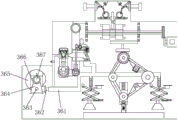
In the figure: an adjusting turntable-1, a device shell-2, a hot-pressing intelligent adjusting device-3, a hot-pressing roller-4, a power switch-5, a pressing plate-6, a first conveying belt-7, a workbench-8, a moving wheel-9, a gas supercharging device-31, a manual adjusting device-32, a power conveying device-33, a lifting adjusting device-34, a jacking telescopic device-35, a negative pressure pump device-36, a first jacking pad-311, a belt rotating wheel-312, a crank-313, a second conveying belt-314, a cam-315, a conveying wheel-316, a jacking rod-317, a pneumatic tube-318, a sealing pad-319, a pushing rod-3110, a reset spring-3111, a hook-3112, a meshing wheel-3113, a driving wheel-3114, a power switch-3111, a hook-type frame-3112, a pressure plate-6, a, Rotating shaft-3115, hook-3116, cam rack-3117, pressurizing cabin-3118, spring rod-3119, adjusting pipe-3120, stop valve-3121, rack-321, rotating wheel-322, adjusting rod-323, support rod-324, spring-325, link rod-326, second jacking pad-327, button-328, limit rod-329, limit slider-3210, matching gear-331, driving wheel-332, power motor-333, cross-334, clamping groove-335, gear shaft-336, matching carriage-337, gear-341, connecting rack-342, adjusting chute-343, middle rotating wheel-344, belt pulley-345, belt-346, carriage-347, sliding block-348, threaded rod-349, 349 and 327, The device comprises a supporting spring-3410, a pressure plate-3411, a cushion block-3412, a limit rotating block-351, an expansion bracket-352, a rubber block-353, a top rod bracket-354, a sliding bracket-355, a pneumatic rod-356, a shell-357, a pressure dividing pipe-361, a joint seat-362, an embedded rod-363, a base-364, a pipe body-365, a power supply box-366 and a negative pressure motor-367.
Detailed Description
In order to make the technical means, the creation characteristics, the achievement purposes and the effects of the invention easy to understand, the invention is further described with the specific embodiments.
Referring to fig. 1-5, the present invention provides an adjustable multifunctional film laminating machine, which comprises: the structure includes: adjusting turntable 1, device shell 2, hot-pressing intelligent adjusting device 3, hot-pressing roller 4, power switch 5, pressing plate 6, first conveyer belt 7, workstation 8, removal wheel 9, two liang of four corners that are parallel to each other of removal wheel 9 embedding device shell 2 lower surface and rather than adopting threaded connection, workstation 8 connects in the center of device shell 2 front surface perpendicularly through the welded mode, first conveyer belt 7 tiles in workstation 8's upper surface and rather than adopting clearance fit to link together simultaneously, hot-pressing roller 4 is located the upper end of device shell 2 inboard surface and rather than fixed connection, hot-pressing intelligent adjusting device 3 is located the right side of device shell 2 upper surface and welds into integrated structure with device shell 2 simultaneously, adjusting turntable 1 embedding device shell 2 left side surface is in the same place with device shell 2 activity fit simultaneously, the power switch 5 is arranged on the right end face of the front surface of the device shell 2;
the hot-pressing intelligent adjusting device 3 is provided with a gas pressurizing device 31, a manual adjusting device 32, a power conveying device 33, a lifting adjusting device 34, a jacking telescopic device 35 and a negative pressure pump device 36;
the negative pressure pump device 36 is arranged on the left side of the inner surface of the device shell 2 and fixedly connected with the inner surface of the device shell 2, the negative pressure pump device 36 is connected with the left end face of the gas supercharging device 31 in a penetrating way, the power conveying device 33 is arranged above the gas supercharging device 31 and meshed with the gas supercharging device to form an integrated structure, the manual adjusting device 32 is arranged in the center above the power conveying device 33, the lifting adjusting device 34 is vertically connected with the lower surface of the power conveying device 33 and mutually meshed with the lower surface of the power conveying device 33, the jacking expansion device 35 and the pressing plate 6 are fixedly connected into an integrated structure in a welding way, the gas supercharging device 31 is provided with a first jacking pad 311, a belt rotating wheel 312, a crank 313, a second conveying belt 314, a cam 315, a conveying wheel 316, a jacking rod 317, a pneumatic tube 318, a sealing gasket 319, a pressing rod 3110, a, A meshing wheel 3113, a transmission wheel 3114, a rotation shaft 3115, a hook 3116, a cam holder 3117, a pressure chamber 3118, a spring lever 3119, a regulating duct 3120, a stop valve 3121, wherein the regulating duct 3120 is embedded in the inner side surface of the pressure chamber 3118 and is integrated therewith, the stop valve 3121 is disposed on the inner side surface of the regulating duct 3120 and is in clearance fit therewith, the two spring levers 3119 form a V shape and is disposed at the upper end of the inner side surface of the pressure chamber 3118 and is fixedly connected therewith, the hook 3116 is fixedly mounted on the outer side surface of the spring lever 3119 by welding, the cam holder 3117 is disposed below the hook 3116 and is movably connected therewith, the first jacking pad 311 is wrapped around the outer side surface above the crank 313 and is in interference fit therewith, the crank 313 and the belt rotating wheel 312 are concentric and are welded together by the shaft 314, the second conveying belt is wrapped around the outer side surface of the belt rotating wheel 312 and is in clearance fit with the conveying wheel 316 on the right side The cam 315 is vertically parallel to the conveying wheel 316 and is concentric with the conveying wheel 316 and is fixedly connected with the same, the ejector rod 317 is arranged at the upper end of the outer side surface of the cam 315, the hook-shaped frame 3112 is positioned above the ejector rod 317 and is movably connected with the ejector rod 317 through a rotating shaft 3115 positioned on the inner side surface of the ejector rod 317, the return spring 3111 wraps the outer side surface of the push rod 3110 and is fixedly connected with the hook-shaped frame 3112 positioned on the upper surface of the push rod 3110, the sealing gasket 319 wraps the lower surface of the push rod 3110, the sealing gasket 319 is arranged on the inner side surface of the pneumatic tube 318 and is in transition fit with the pneumatic tube 318, the conveying wheel 316 is matched with a driving wheel 3114 which is perpendicular to the conveying wheel through a steel rope, the meshing wheel 3113 is meshed with the driving wheel 3114, the manual adjusting device 32 is provided with a rack 321, a rotating wheel 322, the power transmission device comprises a spring 325, a side link 326, a second jacking pad 327, a button 328, a limiting rod 329 and a limiting slider 3210, wherein the rack 321 is embedded into the inner side surface of the limiting slider 3210 and is in clearance fit with the inner side surface, the rotating wheel 322 is vertically connected with the upper surface of the rack 321 and is meshed with the upper surface, the support rod 324 is fixedly mounted in front of the side link 326 in a hinge connection mode, the limiting rod 329 is positioned below the side link 326 and is movably connected with the second jacking pad 327, the spring 325 is positioned above the side link 326 and is mechanically connected with the side link 326, the button 328 is fixedly mounted in the center of the outer side surface of the second jacking pad 327 in a welding mode, the support rod 324 is arranged on the front end surface of the rotating wheel 322, the adjusting rod 323 is positioned in the center of the two racks 321 and is welded with the two racks to form an integrated structure, the power transmission device 33 is provided with a matching, The lifting adjusting device comprises a driving wheel 332, a power motor 333, a cross 334, clamping grooves 335, a gear shaft 336 and a matching sliding frame 337, wherein the matching sliding frame 337 is arranged on the outer side surface of the cross 334 and is connected with the cross 334 in a clearance fit manner, the matching gears 331 are arranged on the left end and the right end of the outer side surface of the cross 334 and are welded with the cross 334, the clamping grooves 335 are embedded into the inner side surface of the matching gear 331, the driving wheel 332 is arranged at the rightmost end of the cross 334 and is fixedly connected with the cross 334, the power motor 333 is vertically connected with the lower surface of the driving wheel 332 and is mutually meshed, the gear shaft 336 is vertically connected with the lower surface of the matching gear 331, the lifting adjusting device 34 is provided with a gear 341, a connecting frame 342, an adjusting sliding groove 343, a transfer wheel 344, a belt 345, a belt 346, a sliding frame, the connecting frame 342 presents a rectangular structure, the pulleys 345 are mounted at four corners of the upper surface of the connecting frame 342, the middle rollers 344 are arranged on the upper surface of the connecting frame 342 and are parallel to each other, the belt 346 wraps the pulleys 345 and is connected with the outer side surface of the middle rollers 344, the gear 341 and the upper pulley 345 are in a concentric circle structure and are fixedly connected with each other, the sliding block 348 is arranged on the lower surface of the lower pulley 345 and is embedded in the inner part of the carriage 347 arranged on the lower surface of the sliding block and is in clearance fit with the lower surface of the sliding block, the threaded rod 349 is perpendicular to the carriage 347 and is in threaded connection with the carriage 347, the cushion block 2 is arranged on the lower surface of the carriage 347 and is connected with the carriage 347 through the supporting spring 3410, the cushion block 3412 is fixedly connected with the center of the upper surface of the pressing plate 3411 through welding, and the top, An expansion bracket 352, a rubber block 353, a top rod bracket 354, a sliding bracket 355, a pneumatic rod 356, a housing 357, wherein the pneumatic rod 356 is embedded in the inner side surface of the housing 357 and movably matched with the housing 357, the expansion bracket 352 is vertically connected to the lower surface of the pneumatic rod 356 and fixedly connected with the pneumatic rod 356, the limit rotating block 351 is located at the left side of the expansion bracket 352 and is in clearance fit with the expansion bracket 352, the sliding bracket 355 and the limit rotating block 351 are parallel to each other and are fixedly connected with the expansion bracket 352, the top rod bracket 354 is located at the lower surface of the expansion bracket 352 and is fixedly connected with the expansion bracket 352 by welding, the rubber block 353 wraps the outer side surface of the top rod bracket 354, the negative pressure pump device 36 is provided with a pressure dividing pipe 361, a joint seat 362, an embedded rod 363, a base 364, a pipe 365, a power supply box 366 and a negative pressure motor 367, the negative pressure motor 367 is located at the, the embedded rod 363 is vertically embedded in the center of the outer side surface of the base 364, the power supply box 366 is located on the left side surface of the negative pressure motor 367 and is electrically connected with the negative pressure motor 367, the negative pressure motor 367 is embedded in the inner side surface of the tube body 365, the tube body 365 is vertically embedded in the inner side surface of the tube body 365, the tube body 365 is combined with the voltage dividing tube 361 through the engaging seat 362 on the right side surface of the tube body, and the three are.
The power transmission device 33 of the present invention refers to a power device capable of supplying power during the operation of the device.
When the device is used, after the device is electrified, the film to be coated is heated and softened by the hot pressing roller 4, the film is coated on a finished product in a flat mode under conveying, then the negative pressure motor 367 is electrified, the gas is conveyed through the pipe body 365 so that the gas enters through the pressure distribution pipe 361, the gas pressure rod 356 is forced to push the gas pressure rod 356 downwards, the pressing plate 3411 is pressed downwards, the pressing plate 6 below is pressed, the coating is attached in a flat mode, when the spacing distance of the pressing plate 6 needs to be adjusted, the left button 328 is used for pushing the front second pushing pad 327 forwards, the connecting rod 326 forwards enables the support rod 324 to move on the rotating wheel 322 to drive the rotating wheel 322 to rotate on the rack 321, the adjusting rod 323 is pushed by the rack 321 to move the matching carriage 337 below the adjusting rod 323 to the left on the rack 334 and the driving wheel 332 rotates by the power motor 333, and the cross 334 rotates after the matching carriage 337 is matched with the clamping groove 335, so that the film is coated The left mating gear 331 rotates and drives the lower gear shaft 336 to rotate, so that the rotation of the driving gear 341 causes the belt pulley 345 to lead the connecting frame 342 to be led under the rotation of the threaded rod 349 under the action of the transfer wheel 347 by the belt 346, so that the sliding block 348 is displaced on the sliding frame 347, so that the pressing plate 3411 is pulled upwards by the cushion block 3112 to enable the pressing plate 346 on the lower part to adjust the distance upwards, when the pressure needs to be adjusted, the right button is pressed to cause the mating sliding frame 337 to right to cause the mating gear 341 to drive the meshing wheel 3113 to rotate so that the lower conveying wheel 316 on the lower part rotates, simultaneously, the front driving wheel 312 drives the crank 313 to rotate by the second conveying belt 314, the stop valve 321 and the negative pressure pump device 36 are opened to intake air inwards, the two spring rods 3119 can be opened and closed orderly by the lower belt of the cam frame 3116 by the rotation of the crank 313, the gas is pressurized by the pushing of the first pushing pad 311, and the pushing rod The pushing rod 3110 is pushed down to press the gas into the pneumatic tube 318, and the pneumatic rod 356 presses and pushes the pressing block 318 to complete the film coating adjustment.
The laminating machine solves the problems that the laminating machine cannot enable the device to adjust the spacing distance of the hot pressing device during laminating work, cannot adjust different hot pressing pressures according to different materials, and cannot enable the laminating machine to be more intelligent.
While there have been shown and described what are at present considered the fundamental principles and essential features of the invention and its advantages, it will be apparent to those skilled in the art that the invention is not limited to the details of the foregoing exemplary embodiments, but is capable of other specific forms without departing from the spirit or essential characteristics thereof. The present embodiments are therefore to be considered in all respects as illustrative and not restrictive, the scope of the invention being indicated by the appended claims rather than by the foregoing description, and all changes which come within the meaning and range of equivalency of the claims are therefore intended to be embraced therein. Any reference sign in a claim should not be construed as limiting the claim concerned.
Furthermore, it should be understood that although the present description refers to embodiments, not every embodiment may contain only a single embodiment, and such description is for clarity only, and those skilled in the art should integrate the description, and the embodiments may be combined as appropriate to form other embodiments understood by those skilled in the art.
Claims (8)
1. The utility model provides a multi-functional laminating machine with adjustable, its structure includes: adjust carousel (1), device casing (2), hot pressing intelligent regulation device (3), hot pressing roller rod (4), switch (5), pressure board (6), first conveyer belt (7), workstation (8), removal wheel (9), its characterized in that:
the moving wheels (9) are embedded into four corners of the lower surface of the device shell (2) in a pairwise parallel manner and are in threaded connection with the four corners, the working platform (8) is vertically connected to the center of the front surface of the device shell (2) in a welding mode, the first conveyer belt (7) is tiled on the upper surface of the workbench (8) and is connected with the workbench together in clearance fit, the hot-pressing roller (4) is positioned at the upper end of the inner side surface of the device shell (2) and is fixedly connected with the device shell, the hot-pressing intelligent adjusting device (3) is positioned on the right side of the upper surface of the device shell (2) and is welded with the device shell (2) to form an integrated structure, the adjusting turntable (1) is embedded into the left side surface of the device shell (2) and is movably matched with the device shell (2), the power switch (5) is arranged on the right end face of the front surface of the device shell (2);
the hot-pressing intelligent adjusting device (3) is provided with a gas pressurizing device (31), a manual adjusting device (32), a power conveying device (33), a lifting adjusting device (34), a jacking telescopic device (35) and a negative pressure pump device (36);
negative pressure pump device (36) are located the left side of device casing (2) internal surface and are in the same place rather than fixed connection simultaneously, negative pressure pump device (36) through connection is in the left side terminal surface of gas supercharging device (31), power transmission device (33) are located the top of gas supercharging device (31) and both mesh simultaneously and are synthesized integrated structure, manual adjusting device (32) are laid in the central authorities of power transmission device (33) top, lift adjusting device (34) are connected perpendicularly and are engaged with each other at the lower surface of power transmission device (33), top moves telescoping device (35) and pressure movable plate (6) and pass through welded mode fixed connection and become integrated structure.
2. The adjustable multifunctional laminating machine of claim 1, wherein: the gas supercharging device (31) is provided with a first jacking pad (311), a belt rotating wheel (312), a crank (313), a second conveying belt (314), a cam (315), a conveying wheel (316), a jacking rod (317), a pneumatic tube (318), a sealing gasket (319), a pushing rod (3110), a return spring (3111), a hook-shaped frame (3112), a meshing wheel (3113), a driving wheel (3114), a rotating shaft (3115), a clamping hook (3116), a cam frame (3117), a pressurizing cabin (3118), a spring rod (3119), an adjusting pipeline (3120) and a stop valve (3121).
3. The adjustable multifunctional laminating machine of claim 2, wherein: the adjusting pipeline (3120) is embedded into the inner surface of the pressurizing chamber (3118) and is in an integral structure, the stop valve (3121) is arranged on the inner surface of the adjusting pipeline (3120) and is in clearance fit with the inner surface, the two spring rods (3119) form a V shape and are arranged at the upper end of the inner surface of the pressurizing chamber (3118) and are fixedly connected with the same, the clamping hook (3116) is fixedly arranged on the outer surface of the spring rod (3119) in a welding manner, the cam rack (3117) is positioned below the clamping hook (3116) and is movably connected with the same, the first jacking pad (311) wraps the outer side surface above the crank (313) and is in interference fit with the same, the crank (313) and the rotating wheel (312) are in a concentric circle structure and are welded together through a shaft, the second conveying belt (314) wraps the outer surface of the rotating wheel (312) and is in clearance fit with the conveying wheel (316) positioned on the right side, the cam (315) is parallel to the conveying wheel (316) up and down and is in a concentric circle structure with the conveying wheel and is fixedly connected with the conveying wheel, the ejector rod (317) is arranged at the upper end of the outer side surface of the cam (315), the hook-shaped frame (3112) is positioned above the ejector rod (317) and is movably connected with the ejector rod (317) through a rotating shaft (3115) positioned on the inner side surface of the ejector rod, the reset spring (3111) wraps the outer surface of the push rod (3110) and is fixedly connected with the hook-shaped frame (3112) on the upper surface, the sealing gasket (319) wraps the lower surface of the pushing rod (3110), the sealing gasket (319) is arranged on the inner side surface of the pneumatic tube (318) and is in transition fit with the inner side surface, the conveying wheel (316) is matched with a transmission wheel (3114) which is perpendicular to the conveying wheel through a steel rope, and the meshing wheel (3113) is meshed with the transmission wheel (3114).
4. The adjustable multifunctional laminating machine of claim 1, wherein: the manual adjusting device (32) is provided with a rack (321), a rotating wheel (322), an adjusting rod (323), a support rod (324), a spring (325), a side link (326), a second jacking pad (327), a button (328), a limiting rod (329) and a limiting slider (3210), the rack (321) is embedded into the inner side surface of the limiting slider (3210) and is in clearance fit with the inner side surface, the rotating wheel (322) is vertically connected with the upper surface of the rack (321) and is meshed with the upper surface, the support rod (324) is fixedly installed in front of the side link (326) in a hinge connection mode, the limiting rod (329) is located below the side link (326) and is movably connected with the second jacking pad (327), the spring (325) is located above the side link (326) and is mechanically connected with the side link (326), the button (328) is fixedly installed in the center of the outer side surface of the second jacking pad (327) in a welding mode, the support rod (324) is arranged on the front end face of the rotating wheel (322), and the adjusting rod (323) is positioned in the center of the two racks (321) and welded with the racks to form an integrated structure.
5. The adjustable multifunctional laminating machine of claim 1, wherein: power transmission device (33) are equipped with cooperation gear (331), action wheel (332), motor power (333), cross (334), draw-in groove (335), gear shaft (336), cooperation balladeur train (337) are located the outside surface of cross (334) and are connected together rather than adopting clearance fit, cooperation gear (331) are located the left and right sides both ends of cross (334) lateral surface and are in the same place rather than the welding, draw-in groove (335) embedding cooperation gear's (331) inboard surface, action wheel (332) are located the rightmost end of cross (334) and are in the same place rather than fixed connection, motor power (333) are connected perpendicularly and are intermeshing at the lower surface of action wheel (332), gear shaft (336) are connected perpendicularly the lower surface of cooperation gear (331).
6. The adjustable multifunctional laminating machine of claim 1, wherein: the lifting adjusting device (34) is provided with a gear (341), a connecting frame (342), an adjusting sliding groove (343), a transfer wheel (344), a belt pulley (345), a belt (346), a sliding frame (347), a sliding block (348), a threaded rod (349), a supporting spring (3410), a pressing plate (3411) and a cushion block (3412), wherein the connecting frame (342) is in a rectangular structure, the belt pulley (345) is installed at four corners of the upper surface of the connecting frame (342), the transfer wheel (344) is arranged on the upper surface of the connecting frame (342) and the two transfer wheels (344) are parallel to each other, the belt (346) wraps the belt pulley (345) and is connected with the outer side surface of the transfer wheel (344), the gear (341) and the belt pulley (345) above are in a concentric circle structure and are fixedly connected with the gear, the sliding block (348) is positioned on the lower surface of the lower belt pulley (345) and is embedded into the sliding frame (347) positioned on the lower surface of the sliding, the threaded rod (349) and the carriage (347) are perpendicular to each other and are connected together in a threaded mode, the cushion block (3412) is arranged on the lower surface of the carriage (347) and is connected together through a supporting spring (3410), and the cushion block (3412) is fixedly connected to the center of the upper surface of the pressing plate (3411) in a welding mode.
7. The adjustable multifunctional laminating machine of claim 1, wherein: the jacking telescopic device (35) is provided with a limiting rotating block (351), a telescopic frame (352), a rubber block (353), a top rod frame (354), a sliding frame (355), a pneumatic rod (356) and a shell (357), wherein the pneumatic rod (356) is embedded into the inner side surface of the shell (357) and is movably matched with the inner side surface of the shell, the telescopic frame (352) is vertically connected to the lower surface of the pneumatic rod (356) and is fixedly connected with the pneumatic rod, the limiting rotating block (351) is located on the left side of the telescopic frame (352) and is in clearance fit with the telescopic frame, the sliding frame (355) and the limiting rotating block (351) are parallel to each other and are fixedly connected with the telescopic frame (352), the top rod frame (354) is located on the lower surface of the telescopic frame (352) and is fixedly connected with the telescopic frame (352) in a welding mode, and the rubber block (353) wraps the outer side surface of the top.
8. The adjustable multifunctional laminating machine of claim 1, wherein: the negative pressure pump device (36) is provided with a pressure dividing pipe (361), a joint seat (362), an embedded rod (363), a base (364), a pipe body (365), a power supply box (366) and a negative pressure motor (367), wherein the negative pressure motor (367) is arranged on the upper surface of the base (364) and fixedly connected with the base (364), the embedded rod (363) is vertically embedded into the center of the outer side surface of the base (364), the power supply box (366) is located on the left side surface of the negative pressure motor (367) and electrically connected with the left side surface, the negative pressure motor (367) is embedded into the inner side surface of the pipe body (365), the pipe body (365) and the pressure dividing pipe (361) are connected together through the joint seat (362) located on the right side surface of the pipe body (365), and.
Priority Applications (1)
| Application Number | Priority Date | Filing Date | Title |
|---|---|---|---|
| CN201711467552.3A CN108189552B (en) | 2017-12-28 | 2017-12-28 | Adjustable multifunctional film laminating machine |
Applications Claiming Priority (1)
| Application Number | Priority Date | Filing Date | Title |
|---|---|---|---|
| CN201711467552.3A CN108189552B (en) | 2017-12-28 | 2017-12-28 | Adjustable multifunctional film laminating machine |
Publications (2)
| Publication Number | Publication Date |
|---|---|
| CN108189552A CN108189552A (en) | 2018-06-22 |
| CN108189552B true CN108189552B (en) | 2020-01-10 |
Family
ID=62586038
Family Applications (1)
| Application Number | Title | Priority Date | Filing Date |
|---|---|---|---|
| CN201711467552.3A Active CN108189552B (en) | 2017-12-28 | 2017-12-28 | Adjustable multifunctional film laminating machine |
Country Status (1)
| Country | Link |
|---|---|
| CN (1) | CN108189552B (en) |
Families Citing this family (4)
| Publication number | Priority date | Publication date | Assignee | Title |
|---|---|---|---|---|
| CN108995373A (en) * | 2018-06-27 | 2018-12-14 | 童春红 | A kind of novel multi-functional laminating machine |
| CN108784512B (en) * | 2018-06-29 | 2021-03-30 | 安徽中宝电梯科技有限公司 | Elevator guide rail cleaning device |
| CN110919924A (en) * | 2019-12-03 | 2020-03-27 | 江苏博阳智能装备有限公司 | Two automatic cutting laminating machine front end feeding mechanisms |
| CN112223895B (en) * | 2020-09-27 | 2022-01-28 | 张家口卷烟厂有限责任公司 | Transmission system of printing device of cigarette making machine |
Citations (6)
| Publication number | Priority date | Publication date | Assignee | Title |
|---|---|---|---|---|
| DE102005022064A1 (en) * | 2005-05-12 | 2006-11-16 | Man Roland Druckmaschinen Ag | Extract system for printing press has separate extract cowls with independent adjustable extract ducts for each emission generating process station |
| CN105235347A (en) * | 2015-11-25 | 2016-01-13 | 孙波 | Workbench lifting cushion block of three-dimensional (3D) laminating machine for carpenters |
| KR101650713B1 (en) * | 2016-01-22 | 2016-08-24 | 코오롱패션머티리얼(주) | Separating device of hydrophobic and multi-porous type polyurethane membrane with softness and thin thickness |
| CN206171910U (en) * | 2016-10-26 | 2017-05-17 | 江苏比微曼智能科技有限公司 | Automatic laminator |
| CN206326978U (en) * | 2016-12-21 | 2017-07-14 | 广州市千彩纸品印刷有限公司 | The coating machine that a kind of hot-pressing roller height can be adjusted |
| CN107081959A (en) * | 2017-03-16 | 2017-08-22 | 赖良财 | A kind of slidingtype gold-stamping die-cutting cuts out individual all-in-one |
-
2017
- 2017-12-28 CN CN201711467552.3A patent/CN108189552B/en active Active
Patent Citations (6)
| Publication number | Priority date | Publication date | Assignee | Title |
|---|---|---|---|---|
| DE102005022064A1 (en) * | 2005-05-12 | 2006-11-16 | Man Roland Druckmaschinen Ag | Extract system for printing press has separate extract cowls with independent adjustable extract ducts for each emission generating process station |
| CN105235347A (en) * | 2015-11-25 | 2016-01-13 | 孙波 | Workbench lifting cushion block of three-dimensional (3D) laminating machine for carpenters |
| KR101650713B1 (en) * | 2016-01-22 | 2016-08-24 | 코오롱패션머티리얼(주) | Separating device of hydrophobic and multi-porous type polyurethane membrane with softness and thin thickness |
| CN206171910U (en) * | 2016-10-26 | 2017-05-17 | 江苏比微曼智能科技有限公司 | Automatic laminator |
| CN206326978U (en) * | 2016-12-21 | 2017-07-14 | 广州市千彩纸品印刷有限公司 | The coating machine that a kind of hot-pressing roller height can be adjusted |
| CN107081959A (en) * | 2017-03-16 | 2017-08-22 | 赖良财 | A kind of slidingtype gold-stamping die-cutting cuts out individual all-in-one |
Also Published As
| Publication number | Publication date |
|---|---|
| CN108189552A (en) | 2018-06-22 |
Similar Documents
| Publication | Publication Date | Title |
|---|---|---|
| CN108189552B (en) | Adjustable multifunctional film laminating machine | |
| CN203077822U (en) | Rotary table continuous type vacuum three-dimensional (3D) heat transfer printing machine | |
| CN201808262U (en) | Automatic film sticking machine | |
| CN108963286A (en) | A kind of lithium battery rubberizing paper equipment | |
| CN106553036A (en) | Automatic steel sheet laminating machine | |
| CN206277787U (en) | A kind of rotary-type full-automatic cold wave machine | |
| CN204776121U (en) | Soft bag production line | |
| CN206154873U (en) | A full -automatic printing inspection machine of moulding | |
| CN109366955B (en) | Plastic uptake flanging machine | |
| CN203305576U (en) | Positive pressure clamp-box corrugated machine | |
| CN109449500A (en) | A kind of lithium battery production equipment | |
| CN213890878U (en) | Flat vulcanization production line for steel wire rope core conveying belt | |
| CN108963341A (en) | The method of lithium battery rubberizing paper | |
| CN212241455U (en) | High-efficient automatic plank laminating machine | |
| CN110034325B (en) | Forming glue machine for electric core head | |
| CN108899587B (en) | Lithium battery Double-face adhesive gummed paper equipment | |
| CN219696515U (en) | An all-in-one battery shaping machine | |
| CN103213427B (en) | A kind of Full-automatic pen plate offset plate machine | |
| CN202969015U (en) | Full-automatic film coating machine for flat plates | |
| CN118205780A (en) | Gluing machine assembly line | |
| CN205470144U (en) | Automatic slip sheet packing equipment | |
| CN201998442U (en) | Brake pad mould movement type rotary hot pressing production line | |
| CN106515208A (en) | Rotating wheel type full-automatic cold stamping machine | |
| CN216272344U (en) | Paste beautiful line and glue mechanism | |
| CN223961881U (en) | A multi-station heat transfer machine |
Legal Events
| Date | Code | Title | Description |
|---|---|---|---|
| PB01 | Publication | ||
| PB01 | Publication | ||
| SE01 | Entry into force of request for substantive examination | ||
| SE01 | Entry into force of request for substantive examination | ||
| TA01 | Transfer of patent application right | ||
| TA01 | Transfer of patent application right |
Effective date of registration: 20191218 Address after: 516300 taiyang'ao industrial city, Baihua Town, Huidong County, Huizhou City, Guangdong Province Applicant after: Huizhou Xufeng new material manufacturing Co., Ltd Address before: 325011 No. 123 Yandang Middle Road, Longwan District, Wenzhou City, Zhejiang Province Applicant before: Qiu Deping |
|
| GR01 | Patent grant | ||
| GR01 | Patent grant |