CN107874454B - Multi-station rotary workbench and drilling and planting processing method thereof - Google Patents
Multi-station rotary workbench and drilling and planting processing method thereof Download PDFInfo
- Publication number
- CN107874454B CN107874454B CN201711314329.5A CN201711314329A CN107874454B CN 107874454 B CN107874454 B CN 107874454B CN 201711314329 A CN201711314329 A CN 201711314329A CN 107874454 B CN107874454 B CN 107874454B
- Authority
- CN
- China
- Prior art keywords
- station
- plate
- workbench
- brush body
- brush
- Prior art date
- Legal status (The legal status is an assumption and is not a legal conclusion. Google has not performed a legal analysis and makes no representation as to the accuracy of the status listed.)
- Active
Links
Images


Classifications
-
- A—HUMAN NECESSITIES
- A46—BRUSHWARE
- A46D—MANUFACTURE OF BRUSHES
- A46D3/00—Preparing, i.e. Manufacturing brush bodies
- A46D3/06—Machines for both drilling bodies and inserting bristles
-
- A—HUMAN NECESSITIES
- A46—BRUSHWARE
- A46D—MANUFACTURE OF BRUSHES
- A46D3/00—Preparing, i.e. Manufacturing brush bodies
- A46D3/08—Parts of brush-making machines
-
- B—PERFORMING OPERATIONS; TRANSPORTING
- B25—HAND TOOLS; PORTABLE POWER-DRIVEN TOOLS; MANIPULATORS
- B25H—WORKSHOP EQUIPMENT, e.g. FOR MARKING-OUT WORK; STORAGE MEANS FOR WORKSHOPS
- B25H1/00—Work benches; Portable stands or supports for positioning portable tools or work to be operated on thereby
Abstract
The invention discloses a multi-station rotary table and a method for drilling and planting processing by the same. The brush body is fed at the first station, then the brush body is rotated 180 degrees to the second station for drilling, the brush body is rotated 90 degrees to the third station for flocking after drilling, the brush body is rotated 90 degrees to the first station for discharging after flocking is finished, and then the feeding of a new brush body is finished at the first station, so that the circulation is performed. The operation of each station is synchronously carried out and mutually noninterfere, and the degree of automation and the production efficiency are high.
Description
Technical Field
The invention relates to manufacturing equipment of a hairbrush, in particular to a multi-station rotary workbench; the invention also relates to a method for drilling and planting processing by the multi-station rotary workbench, which can finish synchronously feeding, drilling, flocking and discharging on the brush plate, and belongs to the technical field of brush processing equipment and processing methods.
Background
The hair-planting machine is widely applied to drilling holes and hair-planting on brush bodies of daily brushes, industrial brushes and the like. For the processing of the plane brush, the drilling and planting workbench of the traditional hair planting machine is positioned below, the brush plate of the plane brush is clamped on the drilling and planting workbench, the length direction of the brush plate of the plane brush extends along the width direction of the drilling and planting workbench, the drilling and planting surface of the brush plate of the plane brush faces upwards, the machine head is positioned above the drilling and planting workbench, the machine head is provided with a drilling mechanism and a planting mechanism, the rear side of the machine head is connected to the machine base, and the machine base extends downwards and is connected to the common base.
When the plane brush is longer, the machine head needs to extend forward for a longer distance due to the fact that the drilling and planting workbench is wider, the cantilever structure leads to the fact that the whole hair planting machine body is large in weight, the space above the drilling and planting workbench is occupied by the drilling mechanism and the hair planting mechanism, automatic feeding and discharging devices cannot be arranged, feeding and discharging of the brush plate are completed by manual assistance, labor intensity is high, and a certain danger exists. In case of an error of an operator, for example, the brush plate with the hair planted is not removed in time, the hair planting nozzle interferes with the brush plate, and the equipment is damaged.
Disclosure of Invention
The invention aims at providing a multi-station rotary workbench, wherein each station can respectively perform feeding, drilling, flocking and discharging, the operation of each station is synchronous and is not interfered with each other, and the automation degree and the production efficiency are high.
In order to achieve the above purpose, the multi-station rotary table comprises a table center cylinder, wherein a top annular guide rail is arranged at the top of the table center cylinder, a plurality of stations are sequentially arranged along the circumference of the top annular guide rail, horizontal station rotary top plates are respectively arranged on the stations of the top annular guide rail, the outer sides of the station rotary top plates are respectively connected with station rotary vertical plates which extend downwards, the lower ends of the station rotary vertical plates are respectively connected with station rotary bottom plates which extend outwards horizontally, table support plates are respectively arranged below the station rotary bottom plates, and brush body tables are respectively arranged on the table support plates.
In contrast to the prior art, the invention has the following beneficial effects: the workbench support plate of each station is suspended below the station rotation bottom plate, and then is suspended on the top annular guide rail through the station rotation vertical plate and the station rotation top plate, and each station can rotate along the top annular guide rail to realize conversion among stations. Taking three stations as an example, the brush body can finish feeding at the first station, then revolve 180 degrees to the second station for drilling, then revolve 90 degrees to the third station for hair planting, and revolve 90 degrees to the first station for blanking after hair planting, thus the cycle is performed. When a certain brush plate is planted in the third station, the next brush plate is drilled in the second station, the two brush plates are synchronously performed, the brush plate is switched after synchronous completion, the first station utilizes the time of drilling holes in the second station and the third station and planting the hair to complete the blanking of the finished brush plate and the feeding of the new brush plate, and all the brush plates synchronously work and do not interfere with each other. Because each station is positioned on different phases, a drilling device, a hair planting device and a feeding and discharging manipulator are conveniently arranged outside each station respectively; and because the brush body workbench is vertically arranged, the processing surface of the brush body faces outwards and directly faces the drill bit and the hair planting nozzle, the cantilever arrangement and transmission modes of the drilling device and the hair planting device are avoided, the production efficiency is improved, and the overall weight of the equipment is reduced.
As an improvement of the invention, the inner and outer circumferential surfaces of the top annular guide rail are respectively provided with a top V-shaped ring with a tip part protruding outwards, the station revolving top plates are respectively and fixedly connected with top roller shafts extending downwards, the lower ends of the top roller shafts are respectively provided with top rollers through bearings, the middle parts of the outer circumferences of the top rollers are respectively provided with top roller V-shaped grooves recessed inwards, and the top roller V-shaped grooves are respectively embedded in the top V-shaped rings on the inner side and the outer side of the top annular guide rail; the lower end face of the top annular guide rail is provided with an annular gear ring, the center of the upper end face of each station revolving top plate is provided with a station conversion servo motor, the output shaft of each station conversion servo motor downwards passes through the station revolving top plate, the lower end head is provided with a station conversion driving gear, and each station conversion driving gear is meshed with the annular gear ring. The station conversion servo motor drives the station conversion driving gear to rotate, the station conversion driving gear is meshed with the annular gear ring, so that the station conversion driving gear advances along the annular gear ring, and the station revolving top plate drives the whole revolving working table to revolve along the top annular guide rail through the cooperation of the top idler wheels and the top V-shaped ring, so that station conversion is realized. The top V-shaped ring is embedded in the V-shaped groove of the top roller, so that the precision of rotation is ensured, loads in lateral and vertical directions can be well borne, the matching friction between the top roller and the top annular guide rail is good, and the noise is low during high-speed operation.
As a further improvement of the invention, a lateral support ring rail is arranged below the annular gear ring and is fixed at the upper part of the workbench center cylinder; the inner end surfaces of the station rotary vertical plates are respectively connected with a lateral supporting plate which horizontally and inwards extends, supporting roller shafts which extend downwards are respectively fixed on the lateral supporting plates, supporting rollers are respectively arranged below the supporting roller shafts, and the supporting rollers are respectively clamped on the inner circumferential surface and the outer circumferential surface of the lateral supporting ring rail. The support rollers below the lateral support plates are respectively clamped at the inner side and the outer side of the lateral support ring rail, so that on one hand, the function of righting is achieved, and the vertical axis of the brush body workbench is ensured to be parallel to the axis of the workbench center cylinder; on the other hand, when the rotary table rotates along the top annular guide rail, the supporting roller can bear the overturning force of the rotary table and the centrifugal force generated by high-speed rotation, so that stable station conversion, high speed and high efficiency are ensured.
As a further improvement of the invention, each workbench support plate is in a U shape with an outward opening, the brush body workbench is respectively arranged in a concave part in the middle of the workbench support plate, the top of each workbench support plate is respectively connected with the lower end of an output shaft of a station rotary speed reducer, the station rotary speed reducer is respectively fixed on the upper end surface of the station rotary bottom plate, and the input end of each station rotary speed reducer is respectively connected with the output end of a station rotary servo motor. The work station rotating servo motor drives the work table support plate to rotate through the work station rotating speed reducer, so that the brush body work table can rotate 360 degrees at each work station, one of the work table rotating brush body work table can meet the requirement of drilling holes and planting hairs on the brush plate with cambered surfaces in the horizontal direction, and the cambered surfaces of the brush plate can be always directed against the drill bit or the hair planting nozzle by rotating the brush body work table, so that the hairs of all parts are perpendicular to the brush plate; secondly, inclined holes can be drilled on the plane brush plate, so that the bristles after bristle planting are inclined at a certain angle with the brush plate; the vertical distance between the processing surface of the brush plate and the axis of the center cylinder of the workbench can be changed by the rotation of the workbench of the brush body and the matching of the drilling and hair planting mechanisms, so that the effect of moving along the Y direction is achieved; the 360-degree rotation of the four-brush workbench can avoid the reverse rotation of the upper row of holes after the processing is completed to the head end of the lower row of holes for processing, and the difficulty of control can be reduced by continuously rotating the upper row of holes to enter the processing of the lower row of holes.
As a further improvement of the invention, station rotary supporting plates are respectively arranged below the bottoms of the workbench supporting plates, the bottom centers of the workbench supporting plates are respectively provided with a workbench supporting plate hinge shaft which protrudes downwards to form the workbench supporting plates, and the workbench supporting plate hinge shafts are supported in the station rotary supporting plates through supporting plate bearings; the lower part of the workbench center cylinder is connected with a bottom annular guide rail, and the inner and outer circumferential surfaces of the bottom annular guide rail are respectively provided with a bottom V-shaped ring with a tip protruding outwards; the inner side of each station rotary supporting plate extends out towards the direction of the central cylinder of the workbench, each station rotary supporting plate is fixedly connected with a bottom roller shaft extending downwards, the lower end of each bottom roller shaft is provided with a bottom roller through a bearing, the middle part of the periphery of each bottom roller is provided with a bottom roller V-shaped groove which is concave inwards, and each bottom roller V-shaped groove is embedded on the bottom V-shaped rings on the inner side and the outer side of the bottom annular guide rail. Because the brush body workbench is longer in vertical length, the lower part is easy to shake; the bottom of the brush body workbench is hinged to the station rotary supporting plate, and the station rotary supporting plate supports the lower end of the rotary workbench through the cooperation of the bottom idler wheels and the bottom V-shaped ring of the bottom annular guide rail, so that the whole rotary workbench is quite stable in the rotary and working processes. The bottom V-shaped ring is embedded in the bottom roller V-shaped groove, so that the precision of rotation is guaranteed, loads in lateral and vertical directions can be well borne, the matching friction between the bottom roller and the bottom annular guide rail is good, and the noise is low during high-speed operation.
As a further improvement of the invention, the base of each brush body workbench is respectively fixed on the outer end surface of a lifting slide plate, the inner end surface of the lifting slide plate is respectively supported on a lifting guide rail through a lifting slide block, the lifting guide rail is fixed on a workbench support plate, a lifting driving servo motor is arranged on the upper part of the outer side surface of the workbench support plate, the output end of the lifting driving servo motor is connected with a lifting screw rod extending downwards, the upper end and the lower end of the lifting screw rod are respectively supported on the workbench support plate through screw rod bearings, the middle part of the lifting screw rod is screwed with a screw rod nut, and the screw rod nut is fixedly connected to the back surface of the lifting slide plate. The lifting drive servo motor drives the lifting screw rod to rotate, the screw rod nut drives the lifting slide plate to slide up and down along the lifting guide rail, the brush body workbench drives the brush plate to do lifting motion, and multiple rows of holes can be processed and planted in the height direction of the rotary workbench, namely the width direction of the brush plate under the condition that the heights of the drill bit and the bristle planting nozzle are unchanged.
As a further improvement of the invention, the upper end and the lower end of the outer end face of the brush body workbench base are respectively provided with a brush body bracket protruding outwards, the top of each brush body bracket is respectively provided with a brush body mounting plate, the brush body mounting plates extend along a horizontal plane, the lower sides of the brush body mounting plates are respectively provided with a lower clamping jaw, the upper sides of the brush body mounting plates are respectively provided with an upper clamping jaw, the inner ends of the lower clamping jaw and the upper clamping jaw are respectively fixed at the two ends of a clamping jaw cylinder, and the clamping jaw cylinder is arranged on the back surface of the brush body mounting plate. Placing the brush plate on a brush body mounting plate, and driving an upper clamping jaw and a lower clamping jaw to synchronously move in opposite directions by shrinkage of a piston rod of a clamping jaw cylinder to clamp the brush plate; the upper end and the lower end of the brush body workbench are respectively clamped with one brush plate, the brush body workbench is matched with double-head drilling and planting, the upper brush plate and the lower brush plate can be synchronously drilled and planted, and the production efficiency is doubled.
As a further improvement of the invention, the top of each brush body bracket is respectively hinged with a brush plate swinging arm, the top of each brush plate swinging arm is respectively fixed with the brush body mounting plate, the free end of each brush plate swinging arm extends towards the direction of the brush body workbench base and is respectively hinged on the vertical connecting plate, the middle part of the brush body workbench base is provided with a brush plate swinging servo motor, the output end of the brush plate swinging servo motor is provided with an eccentric wheel, the circumference of the eccentric wheel is hinged with a connecting rod, and the other end of the connecting rod is hinged with the middle part of the vertical connecting plate. The brush plate swinging servo motor drives the eccentric wheel to rotate through the speed reducer, one end of the eccentric wheel drives the connecting rod to do circular motion, the other end of the connecting rod pulls the vertical connecting plate to swing up and down, the vertical connecting plate drives the inner ends of the two brush plate swinging arms to swing at the same time, the brush plate swinging arms drive the brush plate to do swinging motion in the vertical direction synchronously, if the brush plate is provided with a cambered surface with two high sides and two low sides in the width direction, namely the height direction of the rotary worktable, the swinging can ensure that the drilling and the hair planting depth in the up-down direction of the cambered surface of the brush plate are the same.
As a further improvement of the invention, the first station is located on the front side of the table center cylinder, the second station is located on the rear side of the table center cylinder, and the third station is located on the right side of the table center cylinder. The first station can be used as a feeding and discharging station, the second station can be used as a drilling station, the third station can be used as a flocking station, and because the time of the feeding and discharging station is abundant, the feeding and discharging station arrives at the drilling station and walks 180 degrees, the drilling station arrives at the flocking station, and the flocking station arrives at the discharging station and walks only 90 degrees, so that the time occupied by idle stroke is reduced, and the production efficiency is improved.
The invention further aims to provide a method for drilling and planting by using the multi-station rotary workbench, wherein each station can respectively perform feeding, drilling, flocking and discharging, and the operations of each station are synchronous and do not interfere with each other, so that the production efficiency is high.
In order to achieve the above purpose, the method for drilling and planting processing by the multi-station rotary table comprises the following steps in sequence: the brush body is fed at the first station, then the brush body is rotated 180 degrees to the second station for drilling, the brush body is rotated 90 degrees to the third station for flocking after drilling, the brush body is rotated 90 degrees to the first station for discharging after flocking is finished, and then the feeding of a new brush body is finished at the first station, so that the circulation is performed.
Compared with the prior art, the invention has the following beneficial effects: the workbench support plate of each station is suspended below the station rotation bottom plate, and then is suspended on the top annular guide rail through the station rotation vertical plate and the station rotation top plate, and each station can rotate along the top annular guide rail to realize conversion among stations. When a certain brush plate is planted in the third station, the next brush plate is drilled in the second station, the two brush plates are synchronously performed, the brush plate is switched after synchronous completion, the first station utilizes the time of drilling holes in the second station and the third station and planting the hair to complete the blanking of the finished brush plate and the feeding of the new brush plate, and all the brush plates synchronously work and do not interfere with each other. Because each station is positioned on different phases, a drilling device, a hair planting device and a feeding and discharging manipulator are conveniently arranged outside each station respectively; and because the brush body workbench is vertically arranged, the processing surface of the brush body faces outwards and directly faces the drill bit and the hair planting nozzle, the cantilever arrangement and transmission modes of the drilling device and the hair planting device are avoided, the production efficiency is improved, and the overall weight of the equipment is reduced.
Drawings
Fig. 1 is a front view of a multi-station rotary table according to the present invention.
Fig. 2 is a top view of fig. 1.
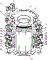
Fig. 3 is a cross-sectional view taken along A-A in fig. 2.
Fig. 4 is a perspective view of fig. 1.
Fig. 5 is a front view of the brush body table of fig. 1 with a station removed.
Fig. 6 is a rear view of fig. 5.
Fig. 7 is a cross-sectional view taken along B-B in fig. 5.
Fig. 8 is a perspective view of fig. 5.
Fig. 9 is a second perspective view of fig. 5.
Fig. 10 is a third perspective view of fig. 5.
FIG. 11 is a diagram of the top ring rail and top roller assembly of FIG. 1.
In the figure: 1. a workbench center barrel; 2. a top annular rail; 2a, a top V-shaped ring; 3a, a station revolving top plate; 3b, a station rotation vertical plate; 3c, a station rotating bottom plate; 3d, a lateral supporting plate; 4. a top roller; 4a, a top roller shaft; 5. an annular gear ring; 6. a station switching servo motor; 6a, station switching driving gears; 7. lateral support ring rails; 8. supporting rollers; 8a, supporting a roller shaft; 9. a station rotating servo motor; 9a, a station rotation speed reducer; 10. a work table support plate; 10a, lifting a guide rail; 11. a bottom annular rail; 12. a station rotary supporting plate; 12a, a pallet bearing; 13. a bottom roller; 13a, a bottom roller shaft; 14. a lifting slide plate; 15. a lifting driving servo motor; 15a, lifting a screw rod; 15b, a lead screw bearing; 15c, a lead screw nut; 16. a brush body workbench; 16a, a brush body mounting plate; 16b, lower clamping jaw; 16c, upper clamping jaw; 16d, clamping jaw cylinder; 16e, swinging the brush plate; 16f, vertical connecting plates; 16g, brushing a plate to swing the servo motor; 16h, connecting rod.
Detailed Description
In the following description of the present invention, the terms "upper", "lower", "front", "rear", "left", "right", "inner", "outer", and the like indicate orientations or positional relationships based on the orientations or positional relationships shown in the drawings, and are merely for convenience in describing the present invention and simplifying the description, and do not mean that the device must have a specific orientation.
As shown in fig. 1 to 4, the multi-station rotary table of the present invention comprises a table center cylinder 1, a top annular guide rail 2 is mounted at the top of the table center cylinder 1, a plurality of stations are sequentially provided along the circumference of the top annular guide rail 2, horizontal station rotary top plates 3a are respectively mounted on each station of the top annular guide rail 2, the outer sides of each station rotary top plate 3a are respectively connected with a station rotary vertical plate 3b extending downwards, the lower ends of each station rotary vertical plate 3b are respectively connected with a station rotary bottom plate 3c extending outwards horizontally, a table support plate 10 is respectively mounted below each station rotary bottom plate 3c, and brush body tables 16 are respectively mounted on each table support plate 10.
The work table support plate 10 of each station is suspended below the station rotation bottom plate 3c, and then is suspended on the top annular guide rail 2 through the station rotation vertical plate 3b and the station rotation top plate 3a, and each station can rotate along the top annular guide rail 2 to realize the conversion between stations. Taking three stations as an example, the brush body can finish feeding at the first station, then revolve 180 degrees to the second station for drilling, then revolve 90 degrees to the third station for hair planting, and revolve 90 degrees to the first station for blanking after hair planting, thus the cycle is performed. When a certain brush plate is planted in the third station, the next brush plate is drilled in the second station, the two brush plates are synchronously performed, the brush plate is switched after synchronous completion, the first station utilizes the time of drilling holes in the second station and the third station and planting the hair to complete the blanking of the finished brush plate and the feeding of the new brush plate, and all the brush plates synchronously work and do not interfere with each other. Because each station is positioned on different phases, a drilling device, a hair planting device and a feeding and discharging manipulator are conveniently arranged outside each station respectively; moreover, as the brush body workbench 16 is arranged vertically, the processing surface of the brush body faces outwards and directly faces the drill bit and the hair planting nozzle, the cantilever arrangement and transmission modes of the drilling device and the hair planting device are avoided, the production efficiency is improved, and the overall weight of the equipment is reduced.
As shown in fig. 5 to 11, the inner and outer circumferential surfaces of the top annular guide rail 2 are respectively provided with a top V-shaped ring 2a with a tip protruding outwards, the top roller shafts 4a extending downwards are respectively and fixedly connected to the station revolving top plates 3a, the lower ends of the top roller shafts 4a are respectively provided with top rollers 4 through bearings, the middle parts of the outer circumferences of the top rollers 4 are respectively provided with inwards concave top roller V-shaped grooves, and the top roller V-shaped grooves are respectively embedded on the top V-shaped rings 2a at the inner side and the outer side of the top annular guide rail 2; the annular gear ring 5 is installed to the lower terminal surface of top annular guide rail 2, and station conversion servo motor 6 is installed respectively in the up end center of each station revolving roof 3a, and the output shaft of each station conversion servo motor 6 passes station revolving roof 3a downwards respectively and the lower end installs station conversion drive gear 6a, and each station conversion drive gear 6a meshes with annular gear ring 5 respectively. The station conversion servo motor 6 drives the station conversion driving gear 6a to rotate, the station conversion driving gear 6a is meshed with the annular gear ring 5, so that the station conversion driving gear 6a advances along the annular gear ring 5, and the station revolving top plate 3a drives the whole revolving table to revolve along the top annular guide rail 2 through the cooperation of the top idler wheel 4 and the top V-shaped ring 2a, so that station conversion is realized. The top V-shaped ring 2a is embedded in the V-shaped groove of the top roller, so that the precision of rotation is ensured, the load in the lateral and vertical directions can be well borne, the matching friction between the top roller 4 and the top annular guide rail 2 is good, and the noise is low during high-speed operation.
A lateral support ring rail 7 is arranged below the annular gear ring 5, and the lateral support ring rail 7 is fixed at the upper part of the workbench center cylinder 1; the inner end surfaces of the station rotary vertical plates 3b are respectively connected with a lateral supporting plate 3d which horizontally and inwards extends, supporting roller shafts 8a which downwards extend are respectively fixed on the lateral supporting plates 3d, supporting rollers 8 are respectively arranged below the supporting roller shafts 8a, and the supporting rollers 8 are respectively clamped on the inner circumferential surface and the outer circumferential surface of the lateral supporting ring rail 7. The supporting rollers 8 below the lateral supporting plate 3d are respectively clamped at the inner side and the outer side of the lateral supporting ring rail 7, so that on one hand, the function of righting is achieved, and the vertical axis of the brush body workbench 16 is ensured to be parallel to the axis of the workbench center cylinder 1; on the other hand, when the rotary table rotates along the top annular guide rail 2, the supporting roller 8 can bear the overturning force of the rotary table and the centrifugal force generated by high-speed rotation, so that stable station conversion is ensured, and the speed and the efficiency are high.
Each work table support plate 10 is U-shaped with an outward opening, brush work tables 16 are respectively arranged in the concave parts of the middle parts of the work table support plates 10, the tops of the work table support plates 10 are respectively connected to the lower ends of output shafts of the station rotary speed reducers 9a, the station rotary speed reducers 9a are respectively fixed to the upper end surfaces of the station rotary bottom plates 3c, and the input ends of the station rotary speed reducers 9a are respectively connected with the output ends of the station rotary servo motors 9. The work station rotary servo motor 9 drives the work table support plate 10 to rotate through the work station rotary speed reducer 9a, so that the brush body work table 16 can rotate 360 degrees at each work station, one of the brush body work table 16 can meet the requirement of drilling holes and planting hairs on the brush plate with cambered surfaces in the horizontal direction, and the cambered surfaces of the brush plate can be always directed against the drill bit or the hair planting mouth by rotating the brush body work table 16, so that the hairs of all parts are perpendicular to the brush plate; secondly, inclined holes can be drilled on the plane brush plate, so that the bristles after bristle planting are inclined at a certain angle with the brush plate; the vertical distance between the processing surface of the brush plate and the axis of the center cylinder 1 of the workbench can be changed by the rotation of the workbench 16 of the brush body and the matching of the drilling and hair planting mechanisms, so that the effect of moving along the Y direction is achieved; the 360-degree rotation of the four-brush workbench 16 can avoid the reverse rotation of the upper row of holes after the processing is completed to the head end of the lower row of holes for processing, and the difficulty of control can be reduced by continuously rotating the lower row of holes.
Station rotary supporting plates 12 are respectively arranged below the bottoms of the workbench supporting plates 10, the centers of the bottoms of the workbench supporting plates 10 are respectively provided with a workbench supporting plate hinge shaft which protrudes downwards to form the workbench supporting plates, and the workbench supporting plate hinge shafts are supported in the station rotary supporting plates 12 through supporting plate bearings 12 a; the lower part of the workbench center cylinder 1 is connected with a bottom annular guide rail 11, and the inner and outer circumferential surfaces of the bottom annular guide rail 11 are provided with bottom V-shaped rings with tips protruding outwards; the inner side of each station rotary supporting plate 12 extends towards the direction of the workbench center cylinder 1, each station rotary supporting plate 12 is fixedly connected with a bottom roller shaft 13a which extends downwards, the lower end of each bottom roller shaft 13a is provided with a bottom roller 13 through a bearing, the middle part of the periphery of each bottom roller 13 is provided with a bottom roller V-shaped groove which is concave inwards, and each bottom roller V-shaped groove is embedded on the bottom V-shaped rings on the inner side and the outer side of the bottom annular guide rail 11. Because the brush body workbench 16 has longer vertical length, the lower part is easy to shake; the bottom of the brush body workbench 16 is hinged on the station rotary supporting plate 12, and the station rotary supporting plate 12 supports the lower end of the rotary workbench through the cooperation of the bottom idler wheels 13 and the bottom V-shaped ring of the bottom annular guide rail 11, so that the whole rotary workbench is quite stable in the rotary and working processes. The bottom V-shaped ring is embedded in the bottom roller V-shaped groove, so that the precision of rotation is ensured, the load in the lateral direction and the vertical direction can be well borne, the matching friction between the bottom roller 13 and the bottom annular guide rail 11 is good, and the noise is low during high-speed operation.
The base of each brush body work table 16 is fixed on the outer terminal surface of lift slide 14 respectively, the interior terminal surface of lift slide 14 is supported on lift guide rail 10a through the lift slider respectively, lift guide rail 10a is fixed on work table mounting plate 10, lift drive servo motor 15 is installed to the lateral surface upper portion of work table mounting plate 10, the output of lift drive servo motor 15 is connected with downwardly extending's lift lead screw 15a, the upper and lower both ends of lift lead screw 15a are supported on work table mounting plate 10 through lead screw bearing 15b respectively, the middle part of lift lead screw 15a has screwed in lead screw nut 15c, lead screw nut 15c fixed connection is at the back of lift slide 14. The lifting drive servo motor 15 drives the lifting screw rod 15a to rotate, the screw rod nut 15c drives the lifting slide plate 14 to slide up and down along the lifting guide rail 10a, the brush body workbench 16 drives the brush plate to do lifting motion, and multiple rows of holes can be processed and planted in the height direction of the rotary workbench, namely the width direction of the brush plate under the condition that the heights of the drill bit and the hair planting nozzle are unchanged.
The upper and lower both ends of the outer terminal surface of brush body workstation 16 base are equipped with the brush body support that outwards protrudes respectively, and brush body mounting panel 16a is installed respectively at the top of each brush body support, and brush body mounting panel 16a extends along the horizontal plane and the downside is equipped with down clamping jaw 16b respectively, and brush body mounting panel 16 a's upside is equipped with upper clamping jaw 16c respectively, and lower clamping jaw 16b and upper clamping jaw 16 c's inner end are fixed respectively at clamping jaw cylinder 16 d's both ends, and clamping jaw cylinder 16d installs the back at brush body mounting panel 16a. Placing the brush plate on the brush body mounting plate 16a, and shrinking the piston rod of the clamping jaw cylinder 16d to drive the upper clamping jaw 16c and the lower clamping jaw 16b to synchronously move in opposite directions so as to clamp the brush plate; the upper end and the lower end of the brush body workbench 16 are respectively clamped with a brush plate, the brush body workbench is matched with double-head drilling and planting, and can synchronously drill holes and plant hairs on the upper brush plate and the lower brush plate, so that the production efficiency is doubled.
The top of each brush body support articulates respectively has brush board swing arm 16e, and the top of each brush board swing arm 16e is fixed with brush body mounting panel 16a respectively, and the free end of each brush board swing arm 16e stretches out to brush body workstation base direction and articulates respectively on vertical connecting plate 16f, and brush board swing servo motor 16g is installed to the mid-mounting of brush body workstation base, and the eccentric wheel is installed to brush board swing servo motor 16 g's output, articulates on the circumference of eccentric wheel has connecting rod 16h, and the other end of connecting rod 16h articulates with vertical connecting plate 16 f's middle part mutually. The brush plate swing servo motor 16g drives the eccentric wheel to rotate through the speed reducer, one end of the eccentric wheel drives the connecting rod 16h to do circular motion, the other end of the connecting rod 16h pulls the vertical connecting plate 16f to swing up and down, the vertical connecting plate 16f drives the inner ends of the two brush plate swing arms 16e to swing at the same time, the brush plate swing arms 16e drive the brush plate to do swing motion in the vertical direction synchronously, and if the brush plate is provided with an arc surface with two high sides and two low sides in the middle in the width direction, namely in the height direction of the rotary worktable, the swing can ensure that the drilling and the hair planting depth in the up-down direction of the arc surface of the brush plate are the same.
The first station is located in the front side of the workbench center cylinder 1, the second station is located in the rear side of the workbench center cylinder 1, and the third station is located in the right side of the workbench center cylinder 1. The first station can be used as a feeding and discharging station, the second station can be used as a drilling station, the third station can be used as a flocking station, and because the time of the feeding and discharging station is abundant, the feeding and discharging station arrives at the drilling station and walks 180 degrees, the drilling station arrives at the flocking station, and the flocking station arrives at the discharging station and walks only 90 degrees, so that the time occupied by idle stroke is reduced, and the production efficiency is improved.
The invention relates to a method for drilling and planting by a multi-station rotary workbench, which sequentially comprises the following steps: the brush body is fed at the first station, then the brush body is rotated 180 degrees to the second station for drilling, the brush body is rotated 90 degrees to the third station for flocking after drilling, the brush body is rotated 90 degrees to the first station for discharging after flocking is finished, and then the feeding of a new brush body is finished at the first station, so that the circulation is performed.
The work table support plate 10 of each station is suspended below the station rotation bottom plate 3c, and then is suspended on the top annular guide rail 2 through the station rotation vertical plate 3b and the station rotation top plate 3a, and each station can rotate along the top annular guide rail 2 to realize the conversion between stations. When a certain brush plate is planted in the third station, the next brush plate is drilled in the second station, the two brush plates are synchronously performed, the brush plate is switched after synchronous completion, the first station utilizes the time of drilling holes in the second station and the third station and planting the hair to complete the blanking of the finished brush plate and the feeding of the new brush plate, and all the brush plates synchronously work and do not interfere with each other. Because each station is positioned on different phases, a drilling device, a hair planting device and a feeding and discharging manipulator are conveniently arranged outside each station respectively; moreover, as the brush body workbench 16 is arranged vertically, the processing surface of the brush body faces outwards and directly faces the drill bit and the hair planting nozzle, the cantilever arrangement and transmission modes of the drilling device and the hair planting device are avoided, the production efficiency is improved, and the overall weight of the equipment is reduced.
The above is only a preferred practical embodiment of the present invention, and is not limited to the scope of the present invention. In addition to the embodiments described above, other embodiments of the invention are possible. All technical schemes formed by equivalent substitution or equivalent transformation fall within the protection scope of the invention. The technical features of the present invention that are not described may be implemented by or using the prior art, and are not described herein.
Claims (10)
1. The utility model provides a multistation rotary table, includes workstation center section of thick bamboo, top annular rail is installed at the top of workstation center section of thick bamboo, its characterized in that: a plurality of stations are sequentially arranged along the circumference of the top annular guide rail, horizontal station rotating top plates are respectively arranged on each station of the top annular guide rail, the outer sides of the station rotating top plates are respectively connected with station rotating vertical plates extending downwards, the lower ends of the station rotating vertical plates are respectively connected with station rotating bottom plates extending outwards horizontally, working table support plates are respectively arranged below the station rotating bottom plates, and brush body working tables are respectively arranged on the working table support plates.
2. The multi-station rotary table according to claim 1, wherein: the upper end of each station revolving top plate is fixedly connected with a top roller shaft extending downwards, the lower end of each top roller shaft is provided with a top roller through a bearing, the middle part of the periphery of each top roller is provided with an inwards concave top roller V-shaped groove, and each top roller V-shaped groove is respectively embedded in the top V-shaped rings on the inner side and the outer side of the top annular guide rail; the lower end face of the top annular guide rail is provided with an annular gear ring, the center of the upper end face of each station revolving top plate is provided with a station conversion servo motor, the output shaft of each station conversion servo motor downwards passes through the station revolving top plate, the lower end head is provided with a station conversion driving gear, and each station conversion driving gear is meshed with the annular gear ring.
3. The multi-station rotary table according to claim 2, wherein: a lateral support ring rail is arranged below the annular gear ring and is fixed at the upper part of the workbench center cylinder; the inner end surfaces of the station rotary vertical plates are respectively connected with a lateral supporting plate which horizontally and inwards extends, supporting roller shafts which extend downwards are respectively fixed on the lateral supporting plates, supporting rollers are respectively arranged below the supporting roller shafts, and the supporting rollers are respectively clamped on the inner circumferential surface and the outer circumferential surface of the lateral supporting ring rail.
4. The multi-station rotary table according to claim 1, wherein: each work table support plate is in an outward U shape with an opening, the brush work table is arranged in a concave position in the middle of each work table support plate, the top of each work table support plate is connected to the lower end of an output shaft of a station rotary speed reducer, the station rotary speed reducer is fixed to the upper end face of the station rotary bottom plate, and the input end of each station rotary speed reducer is connected with the output end of a station rotary servo motor.
5. The multi-station rotary table according to claim 4, wherein: station rotary supporting plates are respectively arranged below the bottoms of the workbench supporting plates, the centers of the bottoms of the workbench supporting plates are respectively provided with a workbench supporting plate hinge shaft protruding downwards, and the workbench supporting plate hinge shafts are supported in the station rotary supporting plates through supporting plate bearings; the lower part of the workbench center cylinder is connected with a bottom annular guide rail, and the inner and outer circumferential surfaces of the bottom annular guide rail are respectively provided with a bottom V-shaped ring with a tip protruding outwards; the inner side of each station rotary supporting plate extends out towards the direction of the central cylinder of the workbench, each station rotary supporting plate is fixedly connected with a bottom roller shaft extending downwards, the lower end of each bottom roller shaft is provided with a bottom roller through a bearing, the middle part of the periphery of each bottom roller is provided with a bottom roller V-shaped groove which is concave inwards, and each bottom roller V-shaped groove is embedded on the bottom V-shaped rings on the inner side and the outer side of the bottom annular guide rail.
6. The multi-station rotary table according to claim 1, wherein: the base of each brush body workbench is respectively fixed on the outer end face of a lifting slide plate, the inner end face of the lifting slide plate is respectively supported on a lifting guide rail through a lifting slide block, the lifting guide rail is fixed on a workbench support plate, a lifting driving servo motor is installed on the upper portion of the outer side face of the workbench support plate, the output end of the lifting driving servo motor is connected with a lifting screw rod extending downwards, the upper end and the lower end of the lifting screw rod are respectively supported on the workbench support plate through screw rod bearings, a screw rod nut is screwed in the middle of the lifting screw rod, and the screw rod nut is fixedly connected with the back face of the lifting slide plate.
7. The multi-station rotary table according to claim 6, wherein: the brush body mounting plate is installed at the top of each brush body support respectively, the brush body mounting plate extends along the horizontal plane and the downside is equipped with down the clamping jaw respectively, the upside of brush body mounting plate is equipped with the clamping jaw respectively, the inner end of clamping jaw and last clamping jaw is fixed at the both ends of clamping jaw cylinder respectively down, the back at brush body mounting plate is installed to the clamping jaw cylinder.
8. The multi-station rotary table according to claim 7, wherein: the top of each brush body support is articulated respectively to have the brush board swing arm, and the top of each brush board swing arm is fixed with respectively the brush body mounting panel, each brush board swing arm's free end stretches out to brush body workstation base direction and articulates respectively on vertical connecting plate, brush body workstation base's mid-mounting has brush board to swing servo motor, the eccentric wheel is installed to brush board swing servo motor's output, articulated on the circumference of eccentric wheel has the connecting rod, the other end of connecting rod with the middle part of vertical connecting plate articulates mutually.
9. The multi-station rotary table according to any one of claims 1 to 8, wherein: first, second and third stations are sequentially arranged along the circumference of the top annular guide rail, the first station is located on the front side of the workbench center cylinder, the second station is located on the rear side of the workbench center cylinder, and the third station is located on the right side of the workbench center cylinder.
10. A method of drilling a workpiece on a multi-station rotary table as claimed in claim 9, comprising the steps of, in order: the brush body is fed at the first station, then the brush body is rotated 180 degrees to the second station for drilling, the brush body is rotated 90 degrees to the third station for flocking after drilling, the brush body is rotated 90 degrees to the first station for discharging after flocking is finished, and then the feeding of a new brush body is finished at the first station, so that the circulation is performed.
Priority Applications (1)
| Application Number | Priority Date | Filing Date | Title |
|---|---|---|---|
| CN201711314329.5A CN107874454B (en) | 2017-12-12 | 2017-12-12 | Multi-station rotary workbench and drilling and planting processing method thereof |
Applications Claiming Priority (1)
| Application Number | Priority Date | Filing Date | Title |
|---|---|---|---|
| CN201711314329.5A CN107874454B (en) | 2017-12-12 | 2017-12-12 | Multi-station rotary workbench and drilling and planting processing method thereof |
Publications (2)
| Publication Number | Publication Date |
|---|---|
| CN107874454A CN107874454A (en) | 2018-04-06 |
| CN107874454B true CN107874454B (en) | 2023-07-07 |
Family
ID=61773772
Family Applications (1)
| Application Number | Title | Priority Date | Filing Date |
|---|---|---|---|
| CN201711314329.5A Active CN107874454B (en) | 2017-12-12 | 2017-12-12 | Multi-station rotary workbench and drilling and planting processing method thereof |
Country Status (1)
| Country | Link |
|---|---|
| CN (1) | CN107874454B (en) |
Families Citing this family (3)
| Publication number | Priority date | Publication date | Assignee | Title |
|---|---|---|---|---|
| CN107928103B (en) * | 2017-12-13 | 2019-04-02 | 扬州市海星数控制刷设备有限公司 | Horizontal ring, which bores, plants all-in-one machine and its carries out boring the method for planting processing |
| CN109363343B (en) * | 2018-11-20 | 2024-01-19 | 扬州市海星数控制刷设备有限公司 | Multi-station rotary hair-planting control system and control method thereof |
| CN111084484B (en) * | 2020-01-22 | 2023-07-25 | 扬州颖特休闲日用制品有限公司 | Automatic production machine for brush heads of painting brushes |
Citations (11)
| Publication number | Priority date | Publication date | Assignee | Title |
|---|---|---|---|---|
| JPH0912001A (en) * | 1995-06-30 | 1997-01-14 | Josuke Ishimaru | Circulating device for table |
| CN2482336Y (en) * | 2001-06-22 | 2002-03-20 | 中国科学院合肥智能机械研究所 | Multi-station drilling inserting bristles machine |
| CN103433568A (en) * | 2013-08-05 | 2013-12-11 | 河南科技大学 | Gear milling machine for forming inner gear ring |
| CN203557120U (en) * | 2013-10-18 | 2014-04-23 | 宁波海天精工股份有限公司 | Numerically-controlled rotary workbench |
| CN105196426A (en) * | 2015-09-24 | 2015-12-30 | 湖北新三友数控机床有限公司 | Numerical-controlled four-station diamond drilling machine |
| CN105692060A (en) * | 2014-11-25 | 2016-06-22 | 中国科学院沈阳自动化研究所 | Multi-station cycle operation circular line |
| CN205343455U (en) * | 2015-11-19 | 2016-06-29 | 海克力斯(上海)自动化设备有限公司 | Automatic three station device of input or output material |
| CN205659144U (en) * | 2016-05-05 | 2016-10-26 | 成都杰仕德科技有限公司 | Rotary type dispensing device of xiLin bottle |
| CN106263499A (en) * | 2016-09-30 | 2017-01-04 | 南京信息职业技术学院 | The automatic embedding hair equipment of swinging six station hairbrush |
| CN107173984A (en) * | 2017-05-17 | 2017-09-19 | 湖北智丰数控机械有限公司 | The three-in-one drilling and hair-planting all-in-one of heavy duty disc, flat board, rod brush |
| CN207604631U (en) * | 2017-12-12 | 2018-07-13 | 扬州市海星数控制刷设备有限公司 | Multi-station turning workbench |
-
2017
- 2017-12-12 CN CN201711314329.5A patent/CN107874454B/en active Active
Patent Citations (11)
| Publication number | Priority date | Publication date | Assignee | Title |
|---|---|---|---|---|
| JPH0912001A (en) * | 1995-06-30 | 1997-01-14 | Josuke Ishimaru | Circulating device for table |
| CN2482336Y (en) * | 2001-06-22 | 2002-03-20 | 中国科学院合肥智能机械研究所 | Multi-station drilling inserting bristles machine |
| CN103433568A (en) * | 2013-08-05 | 2013-12-11 | 河南科技大学 | Gear milling machine for forming inner gear ring |
| CN203557120U (en) * | 2013-10-18 | 2014-04-23 | 宁波海天精工股份有限公司 | Numerically-controlled rotary workbench |
| CN105692060A (en) * | 2014-11-25 | 2016-06-22 | 中国科学院沈阳自动化研究所 | Multi-station cycle operation circular line |
| CN105196426A (en) * | 2015-09-24 | 2015-12-30 | 湖北新三友数控机床有限公司 | Numerical-controlled four-station diamond drilling machine |
| CN205343455U (en) * | 2015-11-19 | 2016-06-29 | 海克力斯(上海)自动化设备有限公司 | Automatic three station device of input or output material |
| CN205659144U (en) * | 2016-05-05 | 2016-10-26 | 成都杰仕德科技有限公司 | Rotary type dispensing device of xiLin bottle |
| CN106263499A (en) * | 2016-09-30 | 2017-01-04 | 南京信息职业技术学院 | The automatic embedding hair equipment of swinging six station hairbrush |
| CN107173984A (en) * | 2017-05-17 | 2017-09-19 | 湖北智丰数控机械有限公司 | The three-in-one drilling and hair-planting all-in-one of heavy duty disc, flat board, rod brush |
| CN207604631U (en) * | 2017-12-12 | 2018-07-13 | 扬州市海星数控制刷设备有限公司 | Multi-station turning workbench |
Also Published As
| Publication number | Publication date |
|---|---|
| CN107874454A (en) | 2018-04-06 |
Similar Documents
| Publication | Publication Date | Title |
|---|---|---|
| WO2019114022A1 (en) | Horizontal annular drilling and planting all-in-one machine and method for drilling and planting same | |
| CN107874454B (en) | Multi-station rotary workbench and drilling and planting processing method thereof | |
| CN104802037B (en) | Double-station numerical control machining center | |
| CN106475841B (en) | A kind of self-feeding having upender and reclaimer device | |
| CN111300267B (en) | Multifunctional clamp for machining | |
| CN103963071A (en) | Mechanical arm | |
| CN111203868A (en) | Robot arm capable of taking workpiece quickly | |
| CN207604631U (en) | Multi-station turning workbench | |
| CN107928102B (en) | Rolling brush disc brush integrated workbench | |
| CN207604632U (en) | Horizontal ring, which bores, plants all-in-one machine | |
| CN206182638U (en) | Workstation is planted to five brills of formula of putting to one side | |
| CN114619254A (en) | High-speed drilling and tapping machine capable of adjusting drilling depth | |
| CN220069115U (en) | Horizontal four-station center workbench | |
| CN116616555A (en) | Horizontal drilling, planting and leveling integrated machine and method for processing hairbrush by same | |
| CN208343787U (en) | A kind of finishing impression processing unit (plant) | |
| CN112571085A (en) | Gantry frame of high-speed five-axis machining center | |
| CN209919327U (en) | Double-spindle shaft vertical machine tool | |
| CN219720042U (en) | Horizontal multifunctional flocking workbench | |
| CN116548725A (en) | Long brush body four-station drilling and planting integrated machine and hair planting method thereof | |
| CN215317315U (en) | Truss manipulator | |
| CN214559034U (en) | Three-position five-axis numerical control machining center | |
| CN213672507U (en) | Mechanical welding and polishing integrated device | |
| CN220406025U (en) | Pneumatic spraying device | |
| CN214818672U (en) | Double-arm truss manipulator | |
| CN211540262U (en) | Heavy machine tool for machining steel structural part |
Legal Events
| Date | Code | Title | Description |
|---|---|---|---|
| PB01 | Publication | ||
| PB01 | Publication | ||
| SE01 | Entry into force of request for substantive examination | ||
| SE01 | Entry into force of request for substantive examination | ||
| GR01 | Patent grant | ||
| GR01 | Patent grant |