CN107848593B - Anti-theft lock for two-wheel vehicle - Google Patents
Anti-theft lock for two-wheel vehicle Download PDFInfo
- Publication number
- CN107848593B CN107848593B CN201680024649.4A CN201680024649A CN107848593B CN 107848593 B CN107848593 B CN 107848593B CN 201680024649 A CN201680024649 A CN 201680024649A CN 107848593 B CN107848593 B CN 107848593B
- Authority
- CN
- China
- Prior art keywords
- theft lock
- locking
- control unit
- bow
- lock
- Prior art date
- Legal status (The legal status is an assumption and is not a legal conclusion. Google has not performed a legal analysis and makes no representation as to the accuracy of the status listed.)
- Active
Links
Images


Classifications
-
- B—PERFORMING OPERATIONS; TRANSPORTING
- B62—LAND VEHICLES FOR TRAVELLING OTHERWISE THAN ON RAILS
- B62H—CYCLE STANDS; SUPPORTS OR HOLDERS FOR PARKING OR STORING CYCLES; APPLIANCES PREVENTING OR INDICATING UNAUTHORIZED USE OR THEFT OF CYCLES; LOCKS INTEGRAL WITH CYCLES; DEVICES FOR LEARNING TO RIDE CYCLES
- B62H5/00—Appliances preventing or indicating unauthorised use or theft of cycles; Locks integral with cycles
- B62H5/20—Appliances preventing or indicating unauthorised use or theft of cycles; Locks integral with cycles indicating unauthorised use, e.g. acting on signalling devices
-
- B—PERFORMING OPERATIONS; TRANSPORTING
- B62—LAND VEHICLES FOR TRAVELLING OTHERWISE THAN ON RAILS
- B62H—CYCLE STANDS; SUPPORTS OR HOLDERS FOR PARKING OR STORING CYCLES; APPLIANCES PREVENTING OR INDICATING UNAUTHORIZED USE OR THEFT OF CYCLES; LOCKS INTEGRAL WITH CYCLES; DEVICES FOR LEARNING TO RIDE CYCLES
- B62H5/00—Appliances preventing or indicating unauthorised use or theft of cycles; Locks integral with cycles
- B62H5/003—Appliances preventing or indicating unauthorised use or theft of cycles; Locks integral with cycles using chains or cables
-
- B—PERFORMING OPERATIONS; TRANSPORTING
- B62—LAND VEHICLES FOR TRAVELLING OTHERWISE THAN ON RAILS
- B62H—CYCLE STANDS; SUPPORTS OR HOLDERS FOR PARKING OR STORING CYCLES; APPLIANCES PREVENTING OR INDICATING UNAUTHORIZED USE OR THEFT OF CYCLES; LOCKS INTEGRAL WITH CYCLES; DEVICES FOR LEARNING TO RIDE CYCLES
- B62H5/00—Appliances preventing or indicating unauthorised use or theft of cycles; Locks integral with cycles
- B62H5/14—Appliances preventing or indicating unauthorised use or theft of cycles; Locks integral with cycles preventing wheel rotation
- B62H5/147—Appliances preventing or indicating unauthorised use or theft of cycles; Locks integral with cycles preventing wheel rotation by means of circular bolts
-
- G—PHYSICS
- G07—CHECKING-DEVICES
- G07C—TIME OR ATTENDANCE REGISTERS; REGISTERING OR INDICATING THE WORKING OF MACHINES; GENERATING RANDOM NUMBERS; VOTING OR LOTTERY APPARATUS; ARRANGEMENTS, SYSTEMS OR APPARATUS FOR CHECKING NOT PROVIDED FOR ELSEWHERE
- G07C9/00—Individual registration on entry or exit
- G07C9/00174—Electronically operated locks; Circuits therefor; Nonmechanical keys therefor, e.g. passive or active electrical keys or other data carriers without mechanical keys
- G07C9/00571—Electronically operated locks; Circuits therefor; Nonmechanical keys therefor, e.g. passive or active electrical keys or other data carriers without mechanical keys operated by interacting with a central unit
-
- E—FIXED CONSTRUCTIONS
- E05—LOCKS; KEYS; WINDOW OR DOOR FITTINGS; SAFES
- E05B—LOCKS; ACCESSORIES THEREFOR; HANDCUFFS
- E05B47/00—Operating or controlling locks or other fastening devices by electric or magnetic means
- E05B2047/0094—Mechanical aspects of remotely controlled locks
-
- G—PHYSICS
- G07—CHECKING-DEVICES
- G07C—TIME OR ATTENDANCE REGISTERS; REGISTERING OR INDICATING THE WORKING OF MACHINES; GENERATING RANDOM NUMBERS; VOTING OR LOTTERY APPARATUS; ARRANGEMENTS, SYSTEMS OR APPARATUS FOR CHECKING NOT PROVIDED FOR ELSEWHERE
- G07C9/00—Individual registration on entry or exit
- G07C9/00174—Electronically operated locks; Circuits therefor; Nonmechanical keys therefor, e.g. passive or active electrical keys or other data carriers without mechanical keys
- G07C2009/00753—Electronically operated locks; Circuits therefor; Nonmechanical keys therefor, e.g. passive or active electrical keys or other data carriers without mechanical keys operated by active electrical keys
- G07C2009/00769—Electronically operated locks; Circuits therefor; Nonmechanical keys therefor, e.g. passive or active electrical keys or other data carriers without mechanical keys operated by active electrical keys with data transmission performed by wireless means
- G07C2009/00793—Electronically operated locks; Circuits therefor; Nonmechanical keys therefor, e.g. passive or active electrical keys or other data carriers without mechanical keys operated by active electrical keys with data transmission performed by wireless means by Hertzian waves
Landscapes
- Engineering & Computer Science (AREA)
- Mechanical Engineering (AREA)
- Physics & Mathematics (AREA)
- General Physics & Mathematics (AREA)
- Lock And Its Accessories (AREA)
Abstract
An anti-theft lock for bicycles and other vehicles driven by persons, which can be switched from a locked state into a driving state, comprises means for operationally securing the anti-theft lock to the vehicle and a control unit (14) for switching the anti-theft lock from a locked state into the driving state and vice versa; characterized in that the control unit (14) has a receiver for the wirelessly transmitted signals of the attached mobile transmitter (10) and means for determining the distance of its relative mobile transmitter (10); when the distance exceeds a threshold value and the vehicle is not driving at the same time, the control unit switches the anti-theft lock into the locked state; and when the distance is below a threshold value, the control unit switches the anti-theft lock into the driving state.
Description
Technical Field
The invention relates to an anti-theft lock for bicycles and other vehicles driven by persons, which can be switched from a locked state into a driving state, comprising
(a) Means for operationally securing the anti-theft lock at the vehicle, and
(b) a control unit for switching the anti-theft lock from the locked state into the driving state and vice versa.
Background
The anti-theft lock is used to disconnect the functionality of the vehicle that is absolutely necessary for driving operation or to block the driving operation. A typical example for such an anti-theft lock is a frame lock (Rahmenschloss). In the case of bicycles with an electric drive, it is however also possible to block the activation of the drive, so that the driving operation is prevented by the motor resistance (motorwinderstandard).
Bicycles and other human-powered vehicles are increasingly being used for daily errands in urban areas. Protecting the vehicle from theft-as it were-is problematic. In addition to cable locks, U-locks or fold locks, frame locks that are securely fitted at the wheel frame have proven suitable.
A bicycle is understood to be a monorail vehicle that can be moved forward by muscle force or by means of a drive. Including bicycles with supporting wheels or additional wheels as well. Examples of such vehicles are a utility bike, an electric bicycle, an electric power assisted bicycle, a high speed electric power assisted bicycle, a tricycle, a scooter (Laufr ä der), a scooter, a bicycle, etc. In motor vehicles, such as cars and trucks, in which the drive is not effected by a person but only by a motor.
The known frame locks lock the rotational movement of one of the wheels by means of a mechanical locking bow (Schliessb ü gel). Thereby, unauthorized use of the vehicle is made difficult or prevented. Frame locks with motor-driven locking bows are known. An electromechanical drive anti-theft lock is shown in EP2357124a2, for example.
As in the case of a frame lock operated by hand, a manual locking or unlocking mechanism is necessary. Similarly, an electronically controlled frame lock must be unlocked with an electronic key. Such an electronic key may be a remote operation device or a mobile phone. In this case, it is just as troublesome and time-consuming to ensure and to ensure that the wheels are secured and unsecured by means of different operating steps for short trips. Accordingly, known embodiments of frame locks provide little comfort benefit to the user.
Unlike in the case of motor-operated vehicles, in the case of vehicles with manual drive and in particular in the case of bicycles, there is no motor which constitutes a natural anti-theft lock when it is not activated. In the case of such vehicles, additional locks or the like which have to be placed exclusively in the locked state are always necessary.
Disclosure of Invention
The object of the invention is to provide a more rapid and comfortable anti-theft system for vehicles of the type mentioned at the outset.
This object is achieved according to the invention in that,
(c) the control unit has a receiver for the wirelessly transmitted signals of the associated mobile transmitter and means for determining its distance from the mobile transmitter;
(d) when the distance exceeds a threshold value and the vehicle is not driving at the same time, the control unit switches the anti-theft lock into the locked state; and is
(e) When the distance is below a threshold value, the control unit switches the immobilizer into the driving state.
In the case of the solution according to the invention, one unit is firmly integrated into the anti-theft lock, and the second unit can be used independently and removably. These units are suitable for determining the distance between a user with a mobile transmitter and a vehicle with a control device. Depending on which the anti-theft lock is controlled.
Preferably, the anti-theft lock comprises a lock which can be fixed at the vehicle with a blocking device for blocking the rotation of the wheel. In particular, it can be provided that the locking device is actuated and the wheel is locked or unlocked. The solution according to the invention has the advantage that a safeguard against theft of the vehicle can be achieved without user manipulation. With the solution according to the invention, the anti-theft protection of the wheel can be forgotten. The invention simplifies especially the theft protection when there is no time or additional restrictions for the use of conventional keys and the operation of the lock. There is likewise no risk of contact with dirty parts of the vehicle, as is the case, for example, with conventional frame locks which are mechanically actuated.
In a further embodiment of the invention, a motor controlled by the control unit is provided for driving the locking device. The motor for locking is then activated. However, it is also possible to lock the motor of the auxiliary drive. The motor brake then prevents the vehicle from being used. Instead of the wheels, other components, such as steering wheels or pedals, can also be locked.
Preferably, the locking device is designed as a curved locking bow, which can be moved between the spokes of the wheel for locking. The locking bow can in particular have a gear-like angular region, into which a gear driven by the motor engages.
In a further embodiment of the invention, the control unit and the mobile transmitter comprise a bidirectional transmitting and receiving unit and the distance is determined by the signal strength of the signals exchanged between the control unit and the mobile transmitter.
The receiver in the control unit may be configured in particular for receiving and for processing signals of a smartphone, tablet or other mobile terminal device. The user has, for example, an inter-frequency radar transceiver, a mobile telephone or a smartphone, which can establish contact with the two-way radio unit of the control unit at the anti-theft lock via a wireless connection. The control unit can determine the transmission or reception intensity of the signal by means of a measuring method. The measurement results can be used to determine the distance between the control unit at the vehicle and the mobile transmitter at the user. The control logic circuit unlocks or secures the vehicle depending on the distance between the mobile wireless unit and the wireless unit of the immobilizer.
In a preferred embodiment, the wireless connection is implemented by means of bluetooth technology or similar radio technology. In this case, a compatible terminal or transponder acts as a digital key. Unlike in the case of known assemblies and keys for motor vehicles, unlocking and locking are effected "automatically" without any intervention by the user. Only the distance and the driving state of the vehicle are decisive. The moving vehicle is never locked.
The use of coded transmission of signals as an additional design provides protection against unauthorized access or operation. In this case, the first device can provide a unique access path, for example, by means of a one-time digital key (e.g., an identification code) in connection with its mobile transmitter. The exchanged code is stored in the memory of the control unit for a long period of time and is compensated with the memory content after the encrypted transmission by the mobile transmitter. Positive compensation enables control for transitions between states.
In a further advantageous embodiment, the immobilizer can be configured uniquely by the user by means of a smartphone application. The sensitivity of the sensor device described below, the distance for the locking and/or unlocking process, the charging state of the energy supply described below, and further states can be shown or configured here. Likewise, the digital key for the pickproof lock may be continued to be delivered to other users. This makes it possible to lease a vehicle without the need to privately deliver keys.
The anti-theft lock may include a sensor for determining the rotational speed of the wheel. From the rotational speed it is possible to determine whether the vehicle is running or not. The anti-theft lock does not lock the running vehicle. In this way, it is ensured that a loss of the mobile transmitter does not trigger an undesired and potentially dangerous locking during driving.
Alternatively or additionally, the anti-theft lock may comprise a tilt and/or acceleration sensor. It can thus be detected, for example, whether the locked vehicle is lifted or otherwise moved. Such a movement can be inferred as a theft if possible, which is signaled by an acoustic and/or optical alarm signal. Such movements can also be communicated to the transmitter, for example a mobile terminal device, by the control device, so that the user can take appropriate measures. The sensors can additionally also be used to detect driving states. Two mutually independent sensor systems are then available for this purpose. Thereby achieving redundancy.
Preferably, the immobilizer has a rechargeable battery that can be charged by the driving movement and is used to supply the control unit and/or the sensor with electrical energy. However, conventional batteries, solar cells or batteries which can be charged in other ways can also be provided. The energy supply provided for this purpose can also be used in the case of a vehicle with an electric auxiliary drive. This energy supply is ensured by a battery integrated into the housing. In this case, for example, the energy system of an electric bicycle or a hub generator (Nabendynamo) or a light generator (Lichtmaschin) of a bicycle serves as a supply device for an integrated battery. Furthermore, the charging electronics ensure continuous availability of the integrated battery and control the charging process. An interface is provided for emergency supply, which makes possible recharging via an external network part or other external energy source (for example, a smartphone, an emergency battery pack, a solar module, etc.).
Preferably, there are two electrically conductive and designated contacts at the accessible housing outer side. If a commercially available 9V battery pack is held at the contacts with the correct polarity, emergency supply can be achieved at any time in the case of an empty internal battery.
In the case of a particularly preferred embodiment of the invention, a sensor for detecting an atypical state and an optical and/or acoustic device for generating an alarm signal in the case of an atypical state are provided. Such an atypical state is a movement of the vehicle in which a theft can be inferred. However, other conditions in terms of weight, temperature, etc. may also be detected.
Preferably, the anti-theft lock has a closed, knock-resistant housing which provides a fastening point for tightening at the wheel frame. An inner frame made of steel plate accommodates the drive mechanism of the locking bow and protects the different parts of the locking part (Sperre) from manipulation.
In a further advantageous embodiment, the anti-theft lock has different fastening points for securing the fastening at the receiving point of the wheel frame in different positions and distances.
Advantageously, the anti-theft lock is equipped with a sensing device in the form of an acceleration or inclination detector and a wheel rotation sensor. Evaluation of the signals by the control algorithm ensures recognition of the driving operation and prevents a locking process during driving.
In a further preferred embodiment, the detection of the charging voltage present or the signal evaluation of the electric bicycle drive system makes it possible to detect a bicycle movement.
In a preferred embodiment, the anti-theft lock is equipped with an acoustic theft alarm system. The sound transducer emits an alarm signal in the case of tilting or wobbling of the bicycle and in the case of switching off the blocking device. Advantageously, the message of the theft attempt is transmitted to the mobile radio unit or smartphone by means of a wireless connection. Thereby alerting the bicycle owner.
In a preferred embodiment, the locking device is embodied as a circular, externally engaging locking bow, which can be set in motion by the drive. The drive is generated by an engaged gear wheel (which in turn is driven by a motor). By means of the drive mechanism, the lock bow can be moved into the open position and into the locked position.
Preferably, the locking bow is fixed in the opened and locked position, respectively, by an additional locking element in the form of a magnetic coil bolt (hubmagnetbolzen). It is thereby possible to reliably prevent a movement of the locking bow against the occupied end position. The magnetic coil bolt is spring loaded and automatically engages into a bore hole mounted in the side of the lock bow. The unlocking process is effected by a coupled control device which, depending on the control logic, pulls the magnetic coil bolt out of the bore hole against the spring stress and again releases the drive of the locking bow. If the next terminal position is reached, the magnetic coil bolt is automatically fixed again.
In a further advantageous embodiment, the locking bow is held in its position by a cam-driven, spring-loaded locking pin which engages in a recess of the locking bow in the unlocked and locked position.
Advantageously, the guidance of the locking bow at the rotating inner ring is implemented by low-friction guide rollers which are received by the spacer bolts of the inner housing frame. Likewise, the guidance of the locking bow in the plane of the axis of rotation is ensured by the guide ribs of the outer housing which are located on the inside. At the driven periphery, the movement of the locking bow is correspondingly ensured with low friction by the drive gear and by the guide gear. The design according to the invention, guided by the locking bow, makes it possible to achieve a long-lasting and low-friction movement of the locking bow using fewer components that can be produced at low cost.
Preferably, the rotation of the locking bow is limited accordingly by the end stop. The end stop can be limited, for example, in the form of a pin in a bore at the periphery of the lock bow. The locking bow has end stops for the open and locked position, respectively. The end stop is formed by a limitation of the rotational path in the case of the corresponding end stop pin abutting against a spacer bolt of the inner frame of the housing.
In a further advantageous embodiment, the anti-theft lock has an additional locking mechanism for the steel cable or the steel chain. The two-wheeled vehicle can be locked by means of a cable or chain using the surroundings, for example a bicycle stand or a fence. This embodiment improves the protection against theft and makes possible the protection of further parts of the wheel.
The invention is particularly advantageous in the case of bicycles which are driven with muscle force and are therefore not locked by the disconnected drive.
Drawings
The embodiments of the invention are the subject of the dependent claims. Embodiments are further described below with reference to the accompanying drawings.
Fig. 1 shows a section in the plane of rotation of the locking bow of an anti-theft lock in the form of a frame lock in the unlocked position.
Fig. 2 shows the locking bow according to fig. 1 in the locked position.
Fig. 3 is a cross-section through the assembly according to fig. 1, perpendicular to the plane of rotation of the locking bow.
Fig. 4 shows an exploded illustration of the components of the assembly according to fig. 1.
Fig. 5 shows an embodiment of the control electronics according to a block diagram.
Fig. 6 illustrates the assembly of an anti-theft lock in the form of a frame lock at a common bicycle frame.
Fig. 7 shows an alternative embodiment of the control electronics according to a block diagram.
Fig. 8 shows a smartphone with a mobile application for a user's operating menu.
Fig. 9 shows a smartphone with a mobile application for a user's configuration menu.
Fig. 10 shows a mobile transponder in the form of a key fob, which is suitable as an alternative to the smartphone or tablet computer according to fig. 9 for controlling the unlocking and locking process of the anti-theft lock as a function of the distance.
Fig. 11 is an exploded illustration of a locking device for a bicycle locking bow, which is closed by means of a spring-loaded locking pin in accordance with a second embodiment.
Fig. 12 shows the assembly according to fig. 11 in a second perspective view.
Fig. 13 shows the assembly according to fig. 11 in the open position.
Fig. 14 shows the assembly according to fig. 11 in the locked position.
Fig. 15 shows a further alternative drive principle of the locking bow by means of a worm drive from the front.
Fig. 16 shows the assembly according to fig. 15 from below.
Fig. 17 is a top view of the assembly according to fig. 15 oriented.
Figure 18 shows a frame lock with a locking mechanism that can lock additional wire rope or chain into the frame lock.
Detailed Description
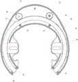
Figure 1 shows an anti-theft lock in the form of a frame lock for a bicycle or other two-wheeled vehicle. As shown in fig. 6, the frame lock 21 is firmly connected with the frame 55 of the bicycle. The locking bow 16 provided at the frame lock 21 is moved between the spokes of the wheel 56 for locking and then locks the rotation of the wheel 56. The locking bow 16 is provided with a rounding 17 on each side in order to improve the guidance in the locked position shown in fig. 2. The housing 22 houses mechanical and electrical components. The inner plate frame 28 is connected to the housing 22 and is screwed to the second frame 31 by means of spacer screws 34 and is fixed in a spaced-apart manner.
The two assembly receptacles 30 enable mounting at a bicycle frame 55, which is equipped with threaded bores 60 for receiving commercially available frame locks. As a guide for the locking bow 16, two toothed wheels 20 and 24 are used, as well as a plurality of radially arranged guide ribs 36, two guide rollers 32 and spacer bolts 34. The two guide rollers 32 serve to support the locking bow 16 with low friction. In addition, the gear 20 has the task of driving the locking bow 16. The engagement 18 at the periphery of the locking bow 16 makes possible the transmission of the drive force of the drive motor 42 and the conversion into a rotational movement of the locking bow 16. The pins 26 in the open position and the pins 27 in the locked position each form an end stop by the locking of the spacer bolts 34.
Fig. 1 shows the locking bow 16 in the open position. The wheel reference numbers are then not blocked. Fig. 2 shows the same components as fig. 1. In fig. 2, the locking bow 16 is visible in the locked position.
Fig. 3 shows the locking of the locking bow 16 by means of the magnet coil 40 and the magnet coil screw 41. The term "locking" is understood here to mean a state in which the locking bow is fixed in its position. In the locked condition, the wheel is in the illustrated front portion by latching of the locking bow. The locking bow 16 has two notches 17 and 19. The recess 17 is provided for latching in the open position of the locking bow 16. The recess 19 is provided for blocking the locking bow 16 in the locked position shown in fig. 2. The magnetic coil bolt 41 is spring-loaded with a spring 43 and automatically locks in one of the notches 17 or 19 once the locking bow 16 occupies one of the end positions. The magnet coil 40 is screwed to the housing 22 and guided through the drive-side plate frame 30. The circuit board 15 is located behind the board frames 31 and 30.
Fig. 4 shows a housing 22 which accommodates an energy carrier (e.g. an accumulator 38 or battery) and a magnetic coil 40. The drive motor 42 is firmly screwed to the drive-side plate frame 28. The drive gear 20 is connected in a force-fitting manner to a drive shaft 45 of the drive motor 42. The locking bow 16 is positioned and guided by the gear wheel 24 in such a way that the drive gear wheel 20 engages in a form-fitting manner in the toothing 18 and can transmit the drive force. The housing 22 accommodates the plate frame 28 or 31 by means of the guide ribs 36. The resulting composite of the housing 22, the plate frame 28 or 31 and the guide roller 32 guides the locking bow 16 during movement into the unlocked or locked position. The unlocked or locked position is limited by an end stop 26.
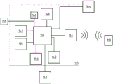
The block diagram depicted in fig. 5 shows the control of the locking or unlocking process for the frame lock 21. In addition to the frame lock 21, the mobile radio unit 10, the detection unit for the wheel rotation 50 and the on-board network 52 are shown. The components of the control electronics described below are located on the circuit board 15 within the housing 22. The central control unit 14 is used to receive, process and output electrical signals of the coupled components shown in fig. 5. The bidirectional bluetooth radio unit 12, which is firmly integrated into the frame lock 21, is connected to the mobile bidirectional bluetooth radio unit 10 by means of a bluetooth wireless connection. The mobile two-way bluetooth radio unit 10 may be implemented in the form of a smart phone, tablet computer or transponder. The central control unit 14 places the drive motor 42 and the magnetic coil 40 in operation depending on the distance of the moving wireless unit 10 relative to the frame lock 21. If the distance of the moving wireless unit relative to the frame lock 21 is greater than, for example, 2 meters, locking is performed. Unlocking is performed if the distance of the moving wireless unit relative to the frame lock 21 is less than, for example, 2 meters. In this case, the user can configure the distance (threshold value) uniquely for the locking or unlocking process. The hysteresis between the threshold values prevents a continuous change of the locking and unlocking process in the case of fluctuations in the measured values.
The battery 44 supplies the control electronics, which are shown in fig. 5 as a whole, and is monitored by the charging electronics 38. The charging electronics recharge the battery 38 when needed via the on-board network 52 of the bicycle. The signal generator 46 generates an audible alarm signal for deterrence in the event of a theft attempt and emits an audible message regarding the lock status. Such states are, for example, "low state of charge of the battery", "locking procedure is not possible", "successful authorization of the user", etc.
The inclination and acceleration sensor 48 recognizes the movements from the vehicle and transmits these information to the central control unit 14. The algorithm evaluates the signal and, in the case of an identified theft attempt, actuates the signal generator 46 or transmits the information to the owner's mobile radio unit 10.
In fig. 6, the frame lock 21 previously described is assembled at the bicycle. A threaded bushing 60 for receiving accessories, which is multiply integrated at the bicycle frame, is used as a fixing point for the frame lock 21. The frame lock 21 is connected to the fastening point 60 of the frame strip 54 of the bicycle frame 54 at the provided assembly receptacle 61 by means of two screws (not shown). The at least two differently arranged fitting accommodation portions 61 make possible the fixing of the frame lock 21 at different accommodation points 60 of the bicycle frame 55. The locking bow 16 is located between the spokes 58 in the locked position and thereby prevents rotation of the wheel 56.
Fig. 7 shows a block diagram for an alternative embodiment. This assembly is similar to that shown in fig. 5 with the following differences: the wireless unit 12 and the central control unit 14 are now integrated together in the microcontroller unit 114. Here a bluetooth chip with an antenna arrangement 154. A detection unit for the vehicle rotation 150 in the form of an optical transmitter and receiver is located on the circuit board 115 and can detect the spokes 58 in the travel path of the locking bolt. The electronic end position detection device 158 makes it possible to detect the position of the locking bow 16 in the open and locked position by means of an electrical contact ring (kontake tschleife). For energy supply, non-rechargeable lithium battery cells 160 are used. In the case of discharged battery cell 160, an emergency supply can be established by means of a 9V battery block via the two-pole contact 156. The locking of the locking bolt 16 in the unlocked and locked position is achieved without the second actuator. The capacitive sensor button 162 forms the operating interface at the frame lock. Which may be used, for example, to enter an unlock code that may be uniquely configured. A multicolored led 164 is used to signal the operational status of the frame lock.
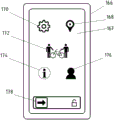
Fig. 8 shows a mobile terminal 166, which shows an operating menu for the frame lock 21 on a screen 167 by means of software. The symbols shown in the case of a selection are correspondingly directed to the lower menus with the corresponding options. The gear symbol 170 leads to a menu setting. This is shown in fig. 9. The orientation symbol 168 leads to a position determination or position indication of the frame lock 21. The lease symbol 172 leads to a secondary menu that allows the digital key to be shared with other users. The information symbol 174 leads to a secondary menu showing status information of the frame lock 21. Such as, for example, battery charge status, connection status, user identification, identification numbers of the immobilizer, interference messages and further statistical and functional data. User symbol 176 leads to the management of the user's account. The frame lock 21 may be manually unlocked or locked via wireless command using a digital slide control 178. The mobile terminal device may be a smartphone, tablet computer or similar device.
Fig. 9 shows a mobile terminal 166, which shows a configuration menu 170 for the frame lock 21 on a screen 167 by means of software. Multiple digital slider controls 180 enable individualized matching of different functional parameters. The slide control with the alarm symbol 182 enables activation or deactivation of the frame lock 21 and selection of the sensitivity of the alarm function. The slide control 184 with a distance symbol (user-direction-bicycle) makes it possible to activate or deactivate the frame lock 21 and to select the distance of the distance-dependent unlocking function. The slide control 186 with a distance symbol (of the user-reverse direction-bicycle) makes it possible to activate or deactivate the frame lock 21 and to select a distance depending on the distance of the locking function.
Fig. 10 shows a transponder in the form of a key fob 188. The key fob is suitable for controlling distance-dependent locking and unlocking of the frame lock 21 and may be used as an alternative to a smartphone, tablet computer or similar mobile terminal device. Here, the key fob does not have the possibility of uniquely configuring the frame lock 21, but rather only makes possible the utilization of the core functions of locking and unlocking depending on the distance and the transmission of status messages (e.g. theft alarm, status of the energy unit and connection status). The key fob 188 is equipped with a channel (durchfuehung) 192 adapted for securing at a key ring or arm band (not shown). The key 190 is adapted to be used to manually unlock or lock the anti-theft lock by pressing it with a wireless signal. The led 194 allows the user to identify operating conditions such as critical battery status, theft alarms, and additional functional messages. The battery box 196 makes it possible to replace the battery cells located inside.
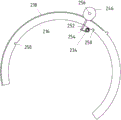
Fig. 11 shows an alternative locking arrangement of the locking bow 216 by means of a spring-loaded locking pin 252. The drive motor 242 is equipped with an offset (abgesetzte) semi-circular drive shaft 244. The drive shaft 244 receives the two unlocking cams 246 and 247 and the free-running drive gear 220 in a force-fitting manner via a geometrically designed shaft receptacle 256. The unlocking cam 246 has a driving pin (Mitnehmerstift) 248. The drive gear 220 rolls off the locking bow 216 equipped with the toothing 218 in a force-fitting and form-fitting manner. A double helical torsion spring or two helical torsion springs 254 is held on the spacer bolt 234 and guided in movement. The locking pin 252 may be spring-loaded into a recess 250 of the locking bow 216.
Fig. 12 shows in a further perspective view, in addition to the components shown in fig. 11, the geometry of the guide groove 260 of the drive gear 220 and the cam curve 258 of the unlocking cams 246 and 247.
Fig. 13 shows the mechanism of the locking device in a front view. The mechanism is shown in the release position. The locking pin 252 is forcibly guided out of the recess 250 of the locking bow 216 by the drive of the unlocking cams 246 and 247. The locking bow 216 is set in rotation and out of the locked position by the drive mechanism (see fig. 13).
Fig. 14 shows the mechanism of the locking device in a front view. The mechanism is shown in the locked position. The position of the unlocking cams 246 and 247 is such that the locking pin 252 is spring-loaded into the recess 250 of the locking bow 216 and thus locks the rotational movement of the locking bow 216.
Fig. 15 shows an alternative drive principle with the aid of a worm drive. A drive worm 302 is fixed to a drive shaft of the drive motor 342. The drive worm 302 engages in the worm gear 300 in a force-fitting and form-fitting manner. The worm gear 300 is connected in a force-fitting manner to the drive shaft 344. The drive gear 320 is likewise connected in a force-fitting manner to the drive shaft 344. The drive gear 320 engages in a force-fitting and form-fitting manner in the engagement section 318 of the lock bow 316. Likewise, the guide gear 324 engages into the engagement portion 318 of the locking bow 316.
FIG. 16 shows the driving principle in a rear view
Fig. 17 shows the driving principle in a top view. In addition to the components shown in fig. 15 and 16, fig. 17 shows a drive shaft 344 and the shaft 304 of the guide gear.
Fig. 18 shows a frame lock 421 equipped with receiving openings 406 adapted to receive and lock bolts 402. Bolt 402 is securely attached to the wire rope and has an annular groove 404. In the locked position of the locking bow 146, the bolt 402 inserted into the receiving opening 406 in advance is locked.
The described device works as follows:
in the initial condition, the bow 16 of the frame lock (as shown in fig. 2) is in the locked position. The terminal position identification means 158 provide the central control unit 14 with feedback about the starting position. The rear wheel 56 of the bicycle is locked by the locking bow 16 and wheel travel is not possible.
The two-way radio unit 12 of the frame lock sends out an identification signal at a periodic distance. The bicycle owner (e.g., in a pants pocket, at a key chain, in a rucksack, etc.) carries the mobile two-way wireless unit 10 with him. The bicycle owner is outside the wireless reach of the frame lock.
The mobile wireless unit 10 searches for the identification signal of the wireless unit 12 at periodic distances. If the bicycle owner with the moving wireless unit moves into the range of the wireless unit 12, then an encrypted wireless connection is made to each other based on the identification signal. If a radio connection is established, the determination of the distance between the radio units 10 and 12 is started by means of a measuring method. The received field strength of the incoming radio signal serves as a measurement quantity. This value is made available via the generic attribute profile (GATT) of the bluetooth low energy standard. The indicator for the reception field strength is called an RSSI (received signal strength indicator) value. The higher the measured field strength, the smaller the distance between the radio units 10 and 12. As long as the field strength does not exceed a certain value, the frame lock remains in the locked position. To validate the measured values, an algorithmic averaging method is used, which calculates a plurality of values for forming the result depending on the measurement time.
If the bicycle owner falls below a certain distance from the bicycle, the signal strength rises above a preset value. If the threshold is exceeded, direct proximity of the user is identified and a turn-on process is introduced. The distance to achieve opening or locking during the process may be in the range between 50 cm and 30 m and may be configurable by the user on demand.
The central control unit 14 evaluates the results of the field strength measurements and controls the opening process in dependence thereon. The distance-dependent control of the unlocking or locking process of the frame lock can be carried out manually by the mobile terminal 116 or the mobile transponder 188, also at the frame lock 21 itself. The mobile terminal 116, the mobile transponder and the frame lock have corresponding operating elements in the form of sensor keys or push buttons.
First, the magnet coil bolt 41 is pulled out of the locking position against a spring bias by actuation of the magnet coil 40. Thus, the opening process of the bow lock 16 is unlocked. Subsequently, the drive motor 42 is supplied with a polarized dc voltage in such a way that the connected drive gear 20 rotates counterclockwise (see fig. 2). The mesh in turn converts the rotational movement of the drive gear 20 clockwise into rotation of the lock bow 16. The locking bow 16 is moved into its end position (see fig. 1). In this case, the magnetic coil bolt 41 is again moved out of the forced position and is urged by a spring against the side of the locking bow 16.
The locking bow 16 is automatically locked if the magnetic coil bolt 41 reaches the notch 17 at the side of the locking bow. The terminal position identifying means 158 signals the arrival of the open position to the central control unit 14. If the bicycle is being used, the detection unit for the wheel rotation 50 recognizes the driving operation and the central control unit 14 locks the locking process. Additionally, movements during driving operation or during standstill are measured by the inclination and acceleration sensor 48 and evaluated by the central control unit 14.
As long as the evaluation of the signal identifies a travel operation, the locking process is not started. If a standstill from a bicycle is recognized, the wireless units 10 and 12 are in turn used to determine the distance between the bicycle owner and the bicycle. In this case, the measurement of the field strength of the radio signal is carried out for the determination of the distance, as described above.
If the bicycle owner with the mobile wireless unit 10 is beyond the set distance from the bicycle, the locking process is triggered. In this case, the central control unit 14 again releases the locking of the locking bow 16 by means of the magnetic coil 40 and controls the movement of the locking bow 16 into the locked position. Thus, the frame lock 21 occupies the starting position again.
The battery 38 supplies the various components of the control electronics, which are shown in fig. 5 or alternatively in fig. 7. As long as the frame lock 21 is in the locked position, the signals of the inclination and acceleration sensor 48 are evaluated by the central control unit 14. If the measured value exceeds the determined threshold value, an acoustic theft alarm is triggered by means of the signal generator 46. Likewise, the mobile wireless unit 10 may send out an audible or tactile message to the bicycle owner in the event of a theft attempt. Thus, an operation attempt at the bicycle or a lifting away of the bicycle can be reliably recognized.
An alternative assembly works as follows:
the anti-theft lock is implemented as a frame lock 21 for a two-wheeled vehicle. The measuring method for the distance detection and the actuation of the locking bow 16 are implemented as previously described. In the case of this alternative assembly, the locking bow 216 is secured and latched in the open or latched position, respectively, by the spring-loaded locking pin 252. In the initial condition, the locking bow 216 is in the open position. The locking pin 252 is held in the notch 250 of the locking bow 216 by the spring loading of the spring 254 and locks the movement of the locking bow 216 against the open position. The locking pins are guided laterally through recesses in the plate frames 28 and 31 in the housing and make possible a vertical movement of the locking pins 252 against the spring loading.
If the locking process is triggered by the control, the drive motor 242 is actuated and the drive shaft 244 is set in rotation. In this case, the unlocking cams 246 and 247, which are connected in a force-fitting manner to the drive shaft 244, are likewise set in rotation. The drive gear 220 is not connected in a force-fitting manner to the drive shaft 244 and therefore does not effect a rotation of the drive shaft 244. The two unlocking cams 246 and 247 are first rotated and, due to their cam curve shape 258, the locking pin 252 is moved out of the recess 250 of the locking bow 216 against a spring bias. The locking of the locking bow 216 in the open position is thus cancelled.
The unlocking cam 246 has a catch in the form of a pin 248. The pin 248 moves in the groove 260 of the drive gear 220 abutting the drive shaft 244. Once the unlocking cams 246 and 247 move the locking pin 252 into the release position, the driving pin 248 of the unlocking cam 246 reaches the end of the slot 260 of the drive gear 220. At this point, the pin 248, due to the force-fit and form-fit connection, drives the drive gear 220 and also sets the drive gear 220 in rotation. The drive gear 220 then sets the locking bow 216 in motion again by means of a force-fit and form-fit connection. In this case, the locking bow is moved into the locking position.
If the locking bow 216 reaches the locked position, the unlocking cams 246 and 247 are again in the starting position and the locking pin 252 is moved by spring loading into the second recess 250 of the locking bow 216 and thus into the locked position. In this position, the locking bow 216 cannot be moved against the locked position by external action. In the case of a subsequent actuation and a movement of the locking bow 216 back into the open position, which is linked to this, the locking device again operates according to the previously described principle.
An alternative assembly works as follows:
the anti-theft lock is implemented as a frame lock 21 for a two-wheeled vehicle. The measuring method for distance detection and the control of the mechanical device depending on this are implemented as previously described components. In the case of this alternative assembly, the drive torque is applied by a worm drive. If the locking or unlocking process is put into operation by the control of the frame lock, the drive motor 342, which is equipped with a gear module 346, drives the gear worm 302 fixed thereto with its drive shaft. The rotating worm 302 in turn drives the worm gear 300. Worm gear 300 drives drive shaft 344 through a force-fit connection. The drive gear 320, which is likewise connected in a force-fitting manner to the drive shaft 344, is set into rotation and drives the locking bolt 316 by means of a form-and force-fitting connection.
Depending on the direction of rotation of the electrical polarization of the dc drive motor 342, the lock bow moves in the locked or unlocked position. The advantage of this assembly lies in the self-locking effect of the worm drive. Because of this self-locking, it is not possible to move the locking bolt against the starting position by an external action. The additional locking means of the locking bow 316 can thus be dispensed with.
An alternative assembly works as follows:
the anti-theft lock is implemented as a frame lock 421 for a two-wheeled vehicle. The measuring method for the distance detection and the actuation of the locking bow 416 are implemented as previously described. The principle of operation of this assembly is not dependent on the drive design or locking mechanism of the locking bow 421. The frame lock 421 has a receiving opening 406 adapted to receive the bolt 402 and lock. Such as a steel cable 400 or chain (not shown) is securely attached to the bolt 402. The wire rope 400 or chain (not shown) is suitable for locking the frame lock 421 and thus the two-wheeled vehicle securely with the surrounding environment, such as a bicycle rack or fence. The bolt 402 is equipped with an annular groove 404. If the bolt 402 is inserted into the receiving opening 406 of the frame lock 421 and the locking process is triggered, the driven locking bow 416 moves in a form-fitting manner through the slot 404 of the bolt 402 and locks the bolt 402 firmly with the frame lock. Thus, the cable 400 or chain (not shown) connected to the surrounding environment is also securely connected to the frame lock. If the opening process is triggered, the locking bow 416 is again moved out of the groove 404 of the bolt 402 and the locking bow is again released. The assembly can reliably prevent the two-wheel vehicle from lifting.
The above components are described in detail. It is obvious, however, that this should not be limiting with regard to the scope of patent protection which is to be determined solely by the patent claims. Many alternatives and identically functioning devices are common to those skilled in the art, which may be used without deviating from the inventive idea. In particular, the geometric arrangement, materials, dimensions and numbers may be varied individually without departing from the inventive idea.
Claims (11)
1. An anti-theft lock for bicycles and other vehicles driven by humans, which can be switched from a locked state into a driving state, comprising:
(a) means for operatively securing the anti-theft lock at the vehicle, and
(b) a control unit (14) for switching the anti-theft lock from a locked state into the driving state and vice versa;
it is characterized in that the preparation method is characterized in that,
(c) the control unit (14) has a receiver (12) for receiving the wirelessly transmitted signal of the associated mobile transmitter (10) and means for determining its distance from the mobile transmitter (10);
(d) -when the distance exceeds a threshold value and the vehicle is not driving at the same time, the control unit (14) switches the anti-theft lock into the locked state; and is
(e) When the distance is below a threshold value, the control unit (14) switches the anti-theft lock into the driving state.
2. Anti-theft lock according to claim 1, characterized in that it comprises a lock (21) that can be fixed at the vehicle, the lock (21) being provided with blocking means for blocking the rotation of the wheel.
3. Anti-theft lock according to claim 2, characterized in that it comprises a motor (42) controlled by the control unit (14) for driving the blocking means.
4. Anti-theft lock according to claim 3, characterized in that the blocking device is configured as a curved locking bow (16) which can be moved for locking between the spokes (58) of a wheel (56).
5. Anti-theft lock according to claim 4, characterized in that the lock bow (16) has an angular range of engagement (18), into which angular range of engagement (18) a gear wheel (20) driven by the motor (42) engages.
6. Anti-theft lock according to one of claims 1 to 5, characterized in that the control unit (14) and the mobile transmitter (10) comprise a transmitting and receiving unit for two-way communication and the distance is determined by the signal strength of the signals exchanged between the control unit (14) and the mobile transmitter (10).
7. Anti-theft lock according to one of claims 1 to 5, characterized in that the receiver (12) is configured in the control unit for receiving and for processing signals of a smartphone, tablet or other mobile terminal device.
8. Anti-theft lock according to any one of claims 1 to 5, characterized in that it comprises a sensor (50) for determining the rotation speed of the wheel.
9. Anti-theft lock according to any one of claims 1 to 5, characterized in that it comprises a tilt and/or acceleration sensor (48).
10. The anti-theft lock according to one of claims 1 to 5, characterized in that it comprises a battery (44) which can be charged by the driving movement or a battery cell (160) for supplying the control unit (14) and/or a sensor with electrical energy.
11. Anti-theft lock according to one of claims 1 to 5, characterized in that it comprises a sensor (48 and 50) for detecting an atypical state and optical and/or acoustic means (164 and 146) for generating a warning signal in the case of the presence of an atypical state.
Applications Claiming Priority (3)
| Application Number | Priority Date | Filing Date | Title |
|---|---|---|---|
| DE102015005419.8 | 2015-04-29 | ||
| DE102015005419.8A DE102015005419A1 (en) | 2015-04-29 | 2015-04-29 | Automatic two-wheeler lock |
| PCT/EP2016/057254 WO2016173804A1 (en) | 2015-04-29 | 2016-04-01 | Immobiliser for two-wheeled vehicles |
Publications (2)
| Publication Number | Publication Date |
|---|---|
| CN107848593A CN107848593A (en) | 2018-03-27 |
| CN107848593B true CN107848593B (en) | 2021-05-25 |
Family
ID=55699625
Family Applications (1)
| Application Number | Title | Priority Date | Filing Date |
|---|---|---|---|
| CN201680024649.4A Active CN107848593B (en) | 2015-04-29 | 2016-04-01 | Anti-theft lock for two-wheel vehicle |
Country Status (6)
| Country | Link |
|---|---|
| US (1) | US10450021B2 (en) |
| EP (1) | EP3288821B1 (en) |
| JP (1) | JP2018522778A (en) |
| CN (1) | CN107848593B (en) |
| DE (1) | DE102015005419A1 (en) |
| WO (1) | WO2016173804A1 (en) |
Families Citing this family (40)
| Publication number | Priority date | Publication date | Assignee | Title |
|---|---|---|---|---|
| KR101922055B1 (en) * | 2016-08-31 | 2018-11-27 | 주식회사 바이시큐 | The method and apparatus about bicycle locking |
| JP2020504938A (en) * | 2016-12-12 | 2020-02-13 | ジャンスー ホンバオ ハードウェア カンパニー リミテッド | System and method for determining anomaly information associated with a vehicle |
| CN110114261B (en) * | 2016-12-19 | 2021-07-27 | 北京骑胜科技有限公司 | System and method for determining abnormality information related to vehicle |
| WO2018113752A1 (en) * | 2016-12-22 | 2018-06-28 | Dongxia Datong (Beijing) Management And Consulting Co., Ltd. | Systems and methods for monitoring a vehicle |
| US10612962B2 (en) * | 2017-01-19 | 2020-04-07 | Loginno Logistic Innovation Ltd. | Method of estimating mass of a shipping container and its contents |
| CN109353431B (en) * | 2017-05-11 | 2020-07-31 | 临海市小核桃工业设计服务部 | Automatic locking shared bicycle |
| KR101922079B1 (en) * | 2017-05-29 | 2018-11-27 | 주식회사 바이시큐 | Bicycle locking apparatus provided with function for preventing abnormal locking and Method thereof |
| DE102017116941A1 (en) * | 2017-07-26 | 2019-01-31 | ABUS August Bremicker Söhne Kommanditgesellschaft | Electronic bicycle lock |
| JP7122500B2 (en) * | 2017-08-10 | 2022-08-22 | パナソニックIpマネジメント株式会社 | bicycle locking device |
| JP2019048490A (en) * | 2017-09-08 | 2019-03-28 | パナソニックIpマネジメント株式会社 | Lock device for bicycles |
| CN107738708A (en) * | 2017-09-30 | 2018-02-27 | 中信戴卡股份有限公司 | A kind of device for being used to control vehicle location |
| US10183713B1 (en) * | 2017-11-06 | 2019-01-22 | LINKA Group Ltd. | Electronic security device for a bicycle |
| US11227073B2 (en) * | 2018-01-23 | 2022-01-18 | Niloy Roy | Anti-theft device |
| DE102018111296A1 (en) * | 2018-05-11 | 2019-11-14 | ABUS August Bremicker Söhne KG | Mobile castle |
| DE102018111286A1 (en) * | 2018-05-11 | 2019-11-14 | ABUS August Bremicker Söhne KG | Hand transmitter for a mobile lock |
| DE102018126356A1 (en) | 2018-06-29 | 2020-01-02 | Haveltec Gmbh | frame lock |
| EP3587227B1 (en) | 2018-06-29 | 2022-03-02 | haveltec GmbH | Frame lock |
| IT201800009118A1 (en) * | 2018-10-03 | 2020-04-03 | Texa Spa | "ANTI-THEFT SYSTEM FOR TWO-WHEEL ELECTRIC VEHICLE" |
| CN111140098A (en) * | 2018-12-14 | 2020-05-12 | 北京悠膳信息技术有限公司 | Vehicle lock control system, vehicle and vehicle lock control method |
| DE102018009866A1 (en) * | 2018-12-19 | 2020-06-25 | Nextbike Gmbh | Anti-theft device |
| CN115584892A (en) | 2018-12-27 | 2023-01-10 | 松下知识产权经营株式会社 | Vehicle control system |
| TWM580534U (en) * | 2019-01-10 | 2019-07-11 | 源文興工業股份有限公司 | Control device interconnecting electric bicycle and electronic lock |
| US12037817B2 (en) * | 2019-05-15 | 2024-07-16 | Rad Power Bikes Inc. | Bicycle security devices and system |
| CN113874278A (en) * | 2019-05-17 | 2021-12-31 | 北京骑胜科技有限公司 | Vehicle lock control device and method and vehicle |
| US20220220773A1 (en) * | 2019-06-18 | 2022-07-14 | Clint BARRETT | An Electric Lock |
| BE1027178B1 (en) | 2019-08-30 | 2020-10-28 | Sentinel Nv | ELECTRONIC RING LOCK WITH REMOVABLE CHAIN LOCK |
| CN110512963B (en) * | 2019-09-04 | 2024-07-30 | 上海钧正网络科技有限公司 | Impact-resistant anti-theft lock plate, switching method and vehicle |
| DE102019215703A1 (en) * | 2019-10-12 | 2021-04-15 | Robert Bosch Gmbh | Electric drive aid |
| CN110949317A (en) * | 2019-11-18 | 2020-04-03 | 上海钧正网络科技有限公司 | Vehicle anti-theft system and anti-theft method thereof and vehicle |
| CN111038623B (en) * | 2019-12-31 | 2021-05-07 | 东莞市帕瓦莱斯智能科技有限公司 | Automatic positioning and locking device for bicycle |
| DE102020114651A1 (en) | 2020-03-03 | 2021-09-09 | Helmut Greb | Locking device; Incentive system; Method for generating at least one bonus signal by means of an incentive system |
| DE102021105647A1 (en) * | 2020-03-17 | 2021-09-23 | ABUS August Bremicker Söhne Kommanditgesellschaft | LOCK |
| DE102020116008A1 (en) * | 2020-06-17 | 2021-12-23 | ABUS August Bremicker Söhne Kommanditgesellschaft | Portable electronic lock |
| DE102020208562A1 (en) | 2020-07-08 | 2022-01-13 | Robert Bosch Gesellschaft mit beschränkter Haftung | Immobilizer, clutch, vehicle transmission, power unit and vehicle method |
| US12015434B2 (en) * | 2021-03-29 | 2024-06-18 | Rad Power Bikes Inc. | Security systems and communication networks for electric bicycles |
| DE102021114205B4 (en) * | 2021-06-01 | 2022-12-29 | ABUS August Bremicker Söhne Kommanditgesellschaft | frame lock |
| USD964843S1 (en) * | 2021-10-28 | 2022-09-27 | Shenzhen Omni Intelligent Technology Co,. Ltd | Electronic horseshoe lock |
| KR102445261B1 (en) * | 2021-12-15 | 2022-09-20 | (주)일렉콤 | Bicycle locking device |
| DE202022103904U1 (en) | 2022-07-12 | 2023-07-13 | Haveltec Gmbh | frame lock |
| DE102023103181A1 (en) | 2023-02-09 | 2024-08-14 | 2Lock GmbH | wheel hub |
Citations (5)
| Publication number | Priority date | Publication date | Assignee | Title |
|---|---|---|---|---|
| JP4176609B2 (en) * | 2003-10-15 | 2008-11-05 | 本田技研工業株式会社 | non-motorized vehicle |
| CN201386437Y (en) * | 2009-04-17 | 2010-01-20 | 何玉峰 | Bluetooth remote control-type safe anti-theft lock |
| CN103038432A (en) * | 2010-08-10 | 2013-04-10 | 大众汽车有限公司 | Lock device |
| WO2014012564A1 (en) * | 2012-07-20 | 2014-01-23 | Velolock Ltd. | Locking device for a bicycle |
| WO2014044111A1 (en) * | 2012-09-24 | 2014-03-27 | 何萍 | Anti-theft alarming bicycle lock with remote control |
Family Cites Families (19)
| Publication number | Priority date | Publication date | Assignee | Title |
|---|---|---|---|---|
| DE19741643A1 (en) * | 1997-09-22 | 1999-03-25 | Klaus Dr Keck | Bicycle or motorcycle locking device |
| US6057657A (en) | 1998-07-02 | 2000-05-02 | Shimano, Inc. | Magnetically operated bicycle antitheft device |
| US20040119583A1 (en) * | 2002-12-19 | 2004-06-24 | Linden Edward A. | Bicycle-mountable lock usable with a remotely controllable bicycle lock and alarm system |
| DE20316619U1 (en) | 2003-10-28 | 2004-03-04 | Betz, Florian | Anti-theft device for bicycles and motorcycles, has a control device to control an electromechanical drive device and a removable signal transmitter to transmit a security code to the control device |
| DE102004054331A1 (en) * | 2003-11-10 | 2005-06-23 | Van Der Veer Designers B.V. | Lock for bicycles etc. consists of lock box with bolt engaging into holes in disc, e.g. brake disc etc |
| EP1818246B1 (en) | 2006-02-14 | 2011-11-30 | ABUS August Bremicker Söhne KG | Electronic bicycle lock |
| US8224313B2 (en) | 2008-09-24 | 2012-07-17 | Centurylink Intellectual Property Llc | System and method for controlling vehicle systems from a cell phone |
| DE102010008055A1 (en) | 2010-02-16 | 2011-08-18 | ABUS August Bremicker Söhne KG, 58300 | Two-wheel lock |
| DE102010008053A1 (en) * | 2010-02-16 | 2011-08-18 | ABUS August Bremicker Söhne KG, 58300 | lock |
| CH703839A2 (en) | 2010-09-30 | 2012-03-30 | Commune Municipale De Bienne Dept D Urbanisme | The management device of a bicycle park. |
| DE102011004464A1 (en) * | 2011-02-21 | 2012-08-23 | Brose Fahrzeugteile Gmbh & Co. Kommanditgesellschaft, Coburg | Safety system for bicycle, particularly for pedelec or electric bicycle, has electric or mechanical locking device, where semi-automatic activation of locking device by bicycle user takes place after outputting request signal |
| DE202012009617U1 (en) | 2012-12-19 | 2013-02-14 | Kurt Ott | Radio lock for bicycles |
| US20140266588A1 (en) * | 2013-03-15 | 2014-09-18 | Mesh Motion, Inc. | Peer-to-peer bike sharing system |
| CN103496360A (en) * | 2013-09-29 | 2014-01-08 | 长城汽车股份有限公司 | Parking braking control device and method |
| CN104512494A (en) | 2013-09-29 | 2015-04-15 | 凹凸电子(武汉)有限公司 | Electric vehicle and management method thereof |
| CN104192227A (en) * | 2014-09-01 | 2014-12-10 | 录可系统公司 | Bicycle management system and method |
| US9512649B2 (en) * | 2014-09-26 | 2016-12-06 | Mohamed Mohamed | Bicycle security device |
| NL2015831B1 (en) * | 2015-11-20 | 2017-06-07 | Bekker Michiel | Key lock. |
| CN207051993U (en) * | 2017-05-04 | 2018-02-27 | 杭州微拜斯科技有限公司 | Shared bicycle smart lock and its control system based on cell phone application control |
-
2015
- 2015-04-29 DE DE102015005419.8A patent/DE102015005419A1/en active Pending
-
2016
- 2016-04-01 US US15/570,165 patent/US10450021B2/en active Active
- 2016-04-01 JP JP2018507769A patent/JP2018522778A/en active Pending
- 2016-04-01 CN CN201680024649.4A patent/CN107848593B/en active Active
- 2016-04-01 EP EP16715278.4A patent/EP3288821B1/en active Active
- 2016-04-01 WO PCT/EP2016/057254 patent/WO2016173804A1/en active Application Filing
Patent Citations (5)
| Publication number | Priority date | Publication date | Assignee | Title |
|---|---|---|---|---|
| JP4176609B2 (en) * | 2003-10-15 | 2008-11-05 | 本田技研工業株式会社 | non-motorized vehicle |
| CN201386437Y (en) * | 2009-04-17 | 2010-01-20 | 何玉峰 | Bluetooth remote control-type safe anti-theft lock |
| CN103038432A (en) * | 2010-08-10 | 2013-04-10 | 大众汽车有限公司 | Lock device |
| WO2014012564A1 (en) * | 2012-07-20 | 2014-01-23 | Velolock Ltd. | Locking device for a bicycle |
| WO2014044111A1 (en) * | 2012-09-24 | 2014-03-27 | 何萍 | Anti-theft alarming bicycle lock with remote control |
Also Published As
| Publication number | Publication date |
|---|---|
| EP3288821A1 (en) | 2018-03-07 |
| JP2018522778A (en) | 2018-08-16 |
| DE102015005419A1 (en) | 2016-11-03 |
| US10450021B2 (en) | 2019-10-22 |
| CN107848593A (en) | 2018-03-27 |
| WO2016173804A1 (en) | 2016-11-03 |
| EP3288821C0 (en) | 2023-08-02 |
| US20180118294A1 (en) | 2018-05-03 |
| EP3288821B1 (en) | 2023-08-02 |
Similar Documents
| Publication | Publication Date | Title |
|---|---|---|
| CN107848593B (en) | Anti-theft lock for two-wheel vehicle | |
| TWI816788B (en) | Portable lock and an unlocking method thereof | |
| KR100606483B1 (en) | Vehicle locking apparatus | |
| CN110469206B (en) | Portable lock | |
| CN110685513B (en) | Two-wheel lock with alarm function | |
| CN109923034B (en) | Battery lock for electric vehicle | |
| TWI802691B (en) | Handheld transmitter for a portable lock, locking system and method of unlocking an electrically actuable portable lock | |
| JP4086115B2 (en) | Bicycle hub with lock mechanism and bicycle lock device | |
| TW201910615A (en) | Electronic two-wheeled vehicle lock | |
| CN111566297B (en) | Electronic lock with mode selection | |
| KR20190076361A (en) | Smart Bike Lock in Saddle | |
| EP3699076B1 (en) | Electric vehicle | |
| CN107826182B (en) | Intelligent bicycle lock mechanism and remote control system thereof | |
| EP1522471A1 (en) | Multifunction car theft alarm lock with tire pressure sensing device | |
| US11383674B2 (en) | Authentication system and corresponding security method | |
| KR20130128970A (en) | Locking apparatus for bicycle | |
| NL2031358B1 (en) | Bicycle with lock | |
| SK500502015A3 (en) | Security anti-theft system for non-motorized vehicles, in particular bicycles | |
| WO2020174720A1 (en) | Electric lock for delivery locker | |
| WO2020174722A1 (en) | Electric lock for delivery locker, and delivery locker | |
| SK500852015U1 (en) | Security anti-theft system for non-motorized vehicles, in particular bicycles |
Legal Events
| Date | Code | Title | Description |
|---|---|---|---|
| PB01 | Publication | ||
| PB01 | Publication | ||
| SE01 | Entry into force of request for substantive examination | ||
| SE01 | Entry into force of request for substantive examination | ||
| GR01 | Patent grant | ||
| GR01 | Patent grant |