CN107813037B - Arc welding joint of Zn-based coated steel sheet - Google Patents
Arc welding joint of Zn-based coated steel sheet Download PDFInfo
- Publication number
- CN107813037B CN107813037B CN201711244322.0A CN201711244322A CN107813037B CN 107813037 B CN107813037 B CN 107813037B CN 201711244322 A CN201711244322 A CN 201711244322A CN 107813037 B CN107813037 B CN 107813037B
- Authority
- CN
- China
- Prior art keywords
- welding
- end portion
- heat input
- speed
- welded
- Prior art date
- Legal status (The legal status is an assumption and is not a legal conclusion. Google has not performed a legal analysis and makes no representation as to the accuracy of the status listed.)
- Active
Links
- 238000003466 welding Methods 0.000 title claims abstract description 363
- 229910000831 Steel Inorganic materials 0.000 title claims abstract description 59
- 239000010959 steel Substances 0.000 title claims abstract description 59
- 238000000034 method Methods 0.000 claims abstract description 52
- 230000007246 mechanism Effects 0.000 claims description 10
- 239000012535 impurity Substances 0.000 claims description 3
- 239000011248 coating agent Substances 0.000 claims description 2
- 238000000576 coating method Methods 0.000 claims description 2
- 239000011148 porous material Substances 0.000 abstract description 36
- 239000011701 zinc Substances 0.000 description 39
- 238000007747 plating Methods 0.000 description 25
- 239000011324 bead Substances 0.000 description 17
- 238000012360 testing method Methods 0.000 description 17
- 239000002184 metal Substances 0.000 description 15
- 229910052751 metal Inorganic materials 0.000 description 15
- 230000008569 process Effects 0.000 description 14
- 239000011800 void material Substances 0.000 description 12
- 239000010410 layer Substances 0.000 description 11
- 230000000694 effects Effects 0.000 description 7
- 230000007423 decrease Effects 0.000 description 6
- 230000000052 comparative effect Effects 0.000 description 5
- 230000007797 corrosion Effects 0.000 description 5
- 238000005260 corrosion Methods 0.000 description 5
- 238000007599 discharging Methods 0.000 description 5
- 239000000463 material Substances 0.000 description 5
- 229910018134 Al-Mg Inorganic materials 0.000 description 4
- 229910018467 Al—Mg Inorganic materials 0.000 description 4
- CURLTUGMZLYLDI-UHFFFAOYSA-N Carbon dioxide Chemical compound O=C=O CURLTUGMZLYLDI-UHFFFAOYSA-N 0.000 description 4
- 238000005259 measurement Methods 0.000 description 4
- 238000007711 solidification Methods 0.000 description 4
- 230000008023 solidification Effects 0.000 description 4
- 239000011247 coating layer Substances 0.000 description 3
- 238000001816 cooling Methods 0.000 description 3
- 238000003618 dip coating Methods 0.000 description 3
- 238000002844 melting Methods 0.000 description 3
- 230000008018 melting Effects 0.000 description 3
- 239000000047 product Substances 0.000 description 3
- 229910000838 Al alloy Inorganic materials 0.000 description 2
- 230000015572 biosynthetic process Effects 0.000 description 2
- 238000009835 boiling Methods 0.000 description 2
- 229910002092 carbon dioxide Inorganic materials 0.000 description 2
- 239000001569 carbon dioxide Substances 0.000 description 2
- 230000006866 deterioration Effects 0.000 description 2
- 230000006872 improvement Effects 0.000 description 2
- 238000003825 pressing Methods 0.000 description 2
- 238000012545 processing Methods 0.000 description 2
- 229910052725 zinc Inorganic materials 0.000 description 2
- 229910018464 Al—Mg—Si Inorganic materials 0.000 description 1
- 208000025865 Ulcer Diseases 0.000 description 1
- HCHKCACWOHOZIP-UHFFFAOYSA-N Zinc Chemical compound [Zn] HCHKCACWOHOZIP-UHFFFAOYSA-N 0.000 description 1
- 229910001297 Zn alloy Inorganic materials 0.000 description 1
- 230000000712 assembly Effects 0.000 description 1
- 238000000429 assembly Methods 0.000 description 1
- 230000008901 benefit Effects 0.000 description 1
- 230000005540 biological transmission Effects 0.000 description 1
- 239000008199 coating composition Substances 0.000 description 1
- 238000007796 conventional method Methods 0.000 description 1
- 238000005536 corrosion prevention Methods 0.000 description 1
- 238000011156 evaluation Methods 0.000 description 1
- 230000002349 favourable effect Effects 0.000 description 1
- 238000010438 heat treatment Methods 0.000 description 1
- 238000003384 imaging method Methods 0.000 description 1
- 238000007654 immersion Methods 0.000 description 1
- 230000002401 inhibitory effect Effects 0.000 description 1
- 238000004519 manufacturing process Methods 0.000 description 1
- 239000000203 mixture Substances 0.000 description 1
- 239000002244 precipitate Substances 0.000 description 1
- 230000002265 prevention Effects 0.000 description 1
- 230000009467 reduction Effects 0.000 description 1
- 239000002436 steel type Substances 0.000 description 1
- 239000000126 substance Substances 0.000 description 1
- 230000001629 suppression Effects 0.000 description 1
- 230000036269 ulceration Effects 0.000 description 1
Images


Classifications
-
- B—PERFORMING OPERATIONS; TRANSPORTING
- B23—MACHINE TOOLS; METAL-WORKING NOT OTHERWISE PROVIDED FOR
- B23K—SOLDERING OR UNSOLDERING; WELDING; CLADDING OR PLATING BY SOLDERING OR WELDING; CUTTING BY APPLYING HEAT LOCALLY, e.g. FLAME CUTTING; WORKING BY LASER BEAM
- B23K9/00—Arc welding or cutting
- B23K9/02—Seam welding; Backing means; Inserts
- B23K9/032—Seam welding; Backing means; Inserts for three-dimensional seams
-
- B—PERFORMING OPERATIONS; TRANSPORTING
- B23—MACHINE TOOLS; METAL-WORKING NOT OTHERWISE PROVIDED FOR
- B23K—SOLDERING OR UNSOLDERING; WELDING; CLADDING OR PLATING BY SOLDERING OR WELDING; CUTTING BY APPLYING HEAT LOCALLY, e.g. FLAME CUTTING; WORKING BY LASER BEAM
- B23K9/00—Arc welding or cutting
- B23K9/095—Monitoring or automatic control of welding parameters
- B23K9/0953—Monitoring or automatic control of welding parameters using computing means
-
- B—PERFORMING OPERATIONS; TRANSPORTING
- B23—MACHINE TOOLS; METAL-WORKING NOT OTHERWISE PROVIDED FOR
- B23K—SOLDERING OR UNSOLDERING; WELDING; CLADDING OR PLATING BY SOLDERING OR WELDING; CUTTING BY APPLYING HEAT LOCALLY, e.g. FLAME CUTTING; WORKING BY LASER BEAM
- B23K9/00—Arc welding or cutting
- B23K9/095—Monitoring or automatic control of welding parameters
- B23K9/0956—Monitoring or automatic control of welding parameters using sensing means, e.g. optical
-
- B—PERFORMING OPERATIONS; TRANSPORTING
- B23—MACHINE TOOLS; METAL-WORKING NOT OTHERWISE PROVIDED FOR
- B23K—SOLDERING OR UNSOLDERING; WELDING; CLADDING OR PLATING BY SOLDERING OR WELDING; CUTTING BY APPLYING HEAT LOCALLY, e.g. FLAME CUTTING; WORKING BY LASER BEAM
- B23K9/00—Arc welding or cutting
- B23K9/23—Arc welding or cutting taking account of the properties of the materials to be welded
-
- C—CHEMISTRY; METALLURGY
- C22—METALLURGY; FERROUS OR NON-FERROUS ALLOYS; TREATMENT OF ALLOYS OR NON-FERROUS METALS
- C22C—ALLOYS
- C22C18/00—Alloys based on zinc
- C22C18/04—Alloys based on zinc with aluminium as the next major constituent
-
- C—CHEMISTRY; METALLURGY
- C23—COATING METALLIC MATERIAL; COATING MATERIAL WITH METALLIC MATERIAL; CHEMICAL SURFACE TREATMENT; DIFFUSION TREATMENT OF METALLIC MATERIAL; COATING BY VACUUM EVAPORATION, BY SPUTTERING, BY ION IMPLANTATION OR BY CHEMICAL VAPOUR DEPOSITION, IN GENERAL; INHIBITING CORROSION OF METALLIC MATERIAL OR INCRUSTATION IN GENERAL
- C23C—COATING METALLIC MATERIAL; COATING MATERIAL WITH METALLIC MATERIAL; SURFACE TREATMENT OF METALLIC MATERIAL BY DIFFUSION INTO THE SURFACE, BY CHEMICAL CONVERSION OR SUBSTITUTION; COATING BY VACUUM EVAPORATION, BY SPUTTERING, BY ION IMPLANTATION OR BY CHEMICAL VAPOUR DEPOSITION, IN GENERAL
- C23C2/00—Hot-dipping or immersion processes for applying the coating material in the molten state without affecting the shape; Apparatus therefor
- C23C2/04—Hot-dipping or immersion processes for applying the coating material in the molten state without affecting the shape; Apparatus therefor characterised by the coating material
- C23C2/06—Zinc or cadmium or alloys based thereon
-
- C—CHEMISTRY; METALLURGY
- C23—COATING METALLIC MATERIAL; COATING MATERIAL WITH METALLIC MATERIAL; CHEMICAL SURFACE TREATMENT; DIFFUSION TREATMENT OF METALLIC MATERIAL; COATING BY VACUUM EVAPORATION, BY SPUTTERING, BY ION IMPLANTATION OR BY CHEMICAL VAPOUR DEPOSITION, IN GENERAL; INHIBITING CORROSION OF METALLIC MATERIAL OR INCRUSTATION IN GENERAL
- C23C—COATING METALLIC MATERIAL; COATING MATERIAL WITH METALLIC MATERIAL; SURFACE TREATMENT OF METALLIC MATERIAL BY DIFFUSION INTO THE SURFACE, BY CHEMICAL CONVERSION OR SUBSTITUTION; COATING BY VACUUM EVAPORATION, BY SPUTTERING, BY ION IMPLANTATION OR BY CHEMICAL VAPOUR DEPOSITION, IN GENERAL
- C23C30/00—Coating with metallic material characterised only by the composition of the metallic material, i.e. not characterised by the coating process
-
- F—MECHANICAL ENGINEERING; LIGHTING; HEATING; WEAPONS; BLASTING
- F16—ENGINEERING ELEMENTS AND UNITS; GENERAL MEASURES FOR PRODUCING AND MAINTAINING EFFECTIVE FUNCTIONING OF MACHINES OR INSTALLATIONS; THERMAL INSULATION IN GENERAL
- F16B—DEVICES FOR FASTENING OR SECURING CONSTRUCTIONAL ELEMENTS OR MACHINE PARTS TOGETHER, e.g. NAILS, BOLTS, CIRCLIPS, CLAMPS, CLIPS OR WEDGES; JOINTS OR JOINTING
- F16B5/00—Joining sheets or plates, e.g. panels, to one another or to strips or bars parallel to them
- F16B5/08—Joining sheets or plates, e.g. panels, to one another or to strips or bars parallel to them by means of welds or the like
-
- B—PERFORMING OPERATIONS; TRANSPORTING
- B23—MACHINE TOOLS; METAL-WORKING NOT OTHERWISE PROVIDED FOR
- B23K—SOLDERING OR UNSOLDERING; WELDING; CLADDING OR PLATING BY SOLDERING OR WELDING; CUTTING BY APPLYING HEAT LOCALLY, e.g. FLAME CUTTING; WORKING BY LASER BEAM
- B23K2101/00—Articles made by soldering, welding or cutting
- B23K2101/18—Sheet panels
-
- B—PERFORMING OPERATIONS; TRANSPORTING
- B23—MACHINE TOOLS; METAL-WORKING NOT OTHERWISE PROVIDED FOR
- B23K—SOLDERING OR UNSOLDERING; WELDING; CLADDING OR PLATING BY SOLDERING OR WELDING; CUTTING BY APPLYING HEAT LOCALLY, e.g. FLAME CUTTING; WORKING BY LASER BEAM
- B23K2101/00—Articles made by soldering, welding or cutting
- B23K2101/34—Coated articles, e.g. plated or painted; Surface treated articles
-
- B—PERFORMING OPERATIONS; TRANSPORTING
- B23—MACHINE TOOLS; METAL-WORKING NOT OTHERWISE PROVIDED FOR
- B23K—SOLDERING OR UNSOLDERING; WELDING; CLADDING OR PLATING BY SOLDERING OR WELDING; CUTTING BY APPLYING HEAT LOCALLY, e.g. FLAME CUTTING; WORKING BY LASER BEAM
- B23K2103/00—Materials to be soldered, welded or cut
- B23K2103/02—Iron or ferrous alloys
- B23K2103/04—Steel or steel alloys
-
- B—PERFORMING OPERATIONS; TRANSPORTING
- B23—MACHINE TOOLS; METAL-WORKING NOT OTHERWISE PROVIDED FOR
- B23K—SOLDERING OR UNSOLDERING; WELDING; CLADDING OR PLATING BY SOLDERING OR WELDING; CUTTING BY APPLYING HEAT LOCALLY, e.g. FLAME CUTTING; WORKING BY LASER BEAM
- B23K2103/00—Materials to be soldered, welded or cut
- B23K2103/08—Non-ferrous metals or alloys
Landscapes
- Engineering & Computer Science (AREA)
- Chemical & Material Sciences (AREA)
- Mechanical Engineering (AREA)
- Materials Engineering (AREA)
- Physics & Mathematics (AREA)
- Plasma & Fusion (AREA)
- Metallurgy (AREA)
- Organic Chemistry (AREA)
- Chemical Kinetics & Catalysis (AREA)
- General Engineering & Computer Science (AREA)
- Theoretical Computer Science (AREA)
- Arc Welding In General (AREA)
- Butt Welding And Welding Of Specific Article (AREA)
- Coating With Molten Metal (AREA)
Abstract
The invention provides an arc welding joint of Zn-based coated steel sheet, which can inhibit the generation of pores at the beginning and end parts and has a pore occupancy rate of less than 30% in the welding length. A welded joint obtained by an arc welding method for a Zn-based plated steel sheet, wherein the method comprises the steps of setting a gap between sheets to be in the range of 0.2 to 1.5 mm: a 1 st step of moving the welding means from a welding start point at a 1 st welding speed and applying a 1 st welding heat input thereto to perform welding, a 2 nd step of moving the welding means at a 2 nd welding speed and applying a 2 nd welding heat input thereto to perform welding, and a 3 rd step of stopping the movement of the welding means and performing welding for 0.1 to 2 seconds at a stop position thereof; the 1 st step includes a welding portion where welding is performed at a 1 st welding speed lower than the 2 nd welding speed and at a 1 st welding heat input higher than the 2 nd welding heat input, and the 3 rd step performs welding at a welding current and a welding voltage lower than those of the 2 nd step.
Description
This application is a divisional application of patent application entitled "arc welding method and arc welded joint for Zn-based plated steel sheet" filed on 2015, 7/31/2015, application No. 201580063975.1.
Technical Field
The present invention relates to arc welding of Zn (zinc) -based coated steel sheets. In particular, the present invention relates to a favorable welded joint in which generation of pores and the like is suppressed.
Background
A Zn-based plated steel sheet obtained by plating a steel sheet with Zn or a Zn alloy is widely used in automobiles, houses, household electrical appliances, and the like because it is excellent in corrosion resistance, strength, workability, and the like, and also has a beautiful appearance. When arc welding is performed on Zn-based plated steel sheets, welding is performed by heating while supplying a wire between the Zn-based plated steel sheets as welding materials.
However, when arc welding is performed on a Zn-based plated steel sheet, the Zn-based plated steel sheet as a material to be welded is heated by an arc. Since the boiling point (906 ℃) of Zn in the plating layer is lower than the melting point of Fe in the steel sheet, Zn vapor is generated during welding, and this vapor enters the welded portion in a molten state, is trapped therein after solidification, and remains as a blowhole (blowhole) in the welded portion. Further, if the pores grow and reach the surface of the welded portion, they may remain as openings (dents).
In particular, in the overlap arc welding, Zn vapor generated from the overlapped portion of the Zn-based plated steel sheet enters the molten portion and rises toward the surface of the molten portion, and tends to form pores and dents in the welded portion and remain (hereinafter, when referred to as "pores", the "dents" are also included).
In order to suppress the generation of the blowholes, various methods have been proposed, and it is effective to provide a gap (gap) between the members to be welded. For example, patent document 1 proposes a method of providing a gap of about 0.5mm between two members to be overlap-welded and discharging generated gas to the opposite side of the welded portion (see page 1, left lower column). Patent document 2 proposes, as a conventional example, a method in which a convex portion is provided on at least one of two base materials, a void is formed around a welded portion, and a vaporized low boiling point substance is diffused and discharged from the void to the outside (see paragraph 0005). These methods are effective for suppressing the generation of blowholes, but it is difficult to sufficiently suppress the generation of blowholes over the entire length of the weld bead. In particular, in a region formed after welding starts (starting end portion) and a region formed before welding ends (end portion), the cooling rate of the weld metal is higher than that in the central portion of the region formed in the middle thereof, and therefore, it is difficult to suppress the occurrence of blowholes, and improvement is required.
Documents of the prior art
Patent document
Patent document 1: japanese laid-open patent publication No. 7-246465
Patent document 2: japanese laid-open patent publication No. 62-179869
Disclosure of Invention
Problems to be solved by the invention
If blowholes are generated when arc welding is performed on a Zn-based plated steel sheet, the blowhole occupancy of the entire welded portion increases, and the joint area of the welded portion decreases, thus greatly affecting the joint strength of the welded portion. Further, if a dent is formed on the outer surface of the welded portion, the appearance of the welded portion is deteriorated.
Therefore, an object of the present invention is to suppress occurrence of blowholes at a leading end portion, that is, a region formed after welding starts, and at a trailing end portion, that is, a region formed before welding ends, in arc welding of a Zn-based plated steel sheet, thereby reducing a blowhole occupancy rate of the entire welded portion.
Means for solving the problems
As a result of intensive studies in view of the above-described problems, the present inventors have found that, when arc welding is performed on a Zn-based plated steel sheet, by providing a gap between the sheets within a predetermined range, applying a welding condition different from that of the central portion to the leading end portion and the trailing end portion of the welded portion with respect to the welding conditions such as welding speed, welding heat input, welding current, and welding voltage, and stopping the arc at the trailing end portion, it is possible to promote the discharge of gas from the weld metal at the leading end portion and the trailing end portion, and suppress the generation of blowholes and dents, and have completed the present invention. Specifically, the present invention provides the following.
(1) The present invention is a method for arc welding a Zn-based plated steel sheet, in which a gap between sheets is set to a range of 0.2 to 1.5mm, and welding is performed by moving a welding mechanism along an overlapping portion of the steel sheet where welding is performed, the method comprising: a first step of moving the welding mechanism from a welding starting point at a first welding speed (1) and applying a first welding heat input to the welding mechanism (1) to perform welding; a 2 nd step of moving the welding means at a 2 nd welding speed to apply a 2 nd welding heat input to perform welding, subsequent to the 1 st step; and a 3 rd step, following the 2 nd step, of stopping the movement of the welding means and performing welding for 0.1 to 2 seconds at the stop position; the 1 st step includes a welded portion that is welded under conditions in which the 1 st welding speed is lower than the 2 nd welding speed and the 1 st welding heat input exceeds the 2 nd welding heat input, and the 3 rd step performs welding at a welding current and a welding voltage that are lower than those in the 2 nd step.
(2) The present invention is the arc welding method for a Zn-based plated steel sheet according to (1), wherein a start end portion of the welded portion after the 1 st step is a region of 10 to 40% of the total welding length, and a tail end portion of the welded portion after the 3 rd step is a region of 10 to 20% of the total welding length.
(3) The present invention is the arc welding method for Zn-based plated steel sheet according to the above (1) or (2), wherein in the step 1, welding is started from one end portion of the overlapped portion and welding is performed toward the other end portion, and the welding heat input in the step 1 is heat more than 1.2 times the welding heat input in the step 2.
(4) The present invention is the arc welding method for a Zn-based plated steel sheet according to the above (1) or (2), wherein in the step 1, welding is performed from a welding start point located more inside than one end of the overlap portion toward the one end, then welding is performed from the one end toward the other end by reversing the welding, the welding speed for welding toward the one end is lower than the welding speed in the step 2, the welding heat input is more than 1.2 times the welding heat input in the step 2, and the welding for welding toward the other end is performed at the same welding speed as the welding speed in the step 2.
(5) The present invention is the arc welding method for a Zn-based coated steel sheet according to any one of (1) to (4) above, wherein the void occupancy is less than 30% over the entire welding length.
(6) The present invention is the arc welding method for a Zn-coated steel sheet according to any one of (1) to (5) above, wherein the Zn-coated steel sheet has a hot-dip coating layer containing, in mass%, 4.0 to 22.0% of Al, 0.05 to 10.0% of Mg, 0 to 0.10% of Ti, 0 to 0.05% of B, 0 to 2.0% of Si, and 0 to 2.5% of Fe, with the balance consisting of Zn and unavoidable impurities.
(7) The present invention is the arc welding method according to any one of (1) to (6) above, wherein the Zn-based plated steel sheet has a plating deposit amount per surface of 20 to 250g/m2The thickness of the plate is 1.6 to 6.0 mm.
(8) The present invention is an arc welding joint formed by the arc welding method according to any one of the above (1) to (7), characterized in that the void occupancy is less than 30% over the entire welding length.
ADVANTAGEOUS EFFECTS OF INVENTION
According to the present invention, in arc welding in which the inter-plate gap of the Zn-based plated steel sheet is provided, the occurrence of the blowholes and dents at the leading end portion and the trailing end portion is suppressed, and the blowhole occupancy of the entire welded portion can be reduced. This helps prevent a decrease in welding strength and improves the safety and reliability of the welded portion. Further, a welded portion having a good appearance can be obtained.
Drawings
FIG. 1 is a schematic view showing a T-shaped test piece used in examples, wherein (a) is a perspective view and (b) is a front view.
Fig. 2 is a view schematically showing a welding portion.
FIG. 3 is a graph showing the relationship between the plate interspace and the gas hole occupancy in the examples.
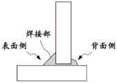
Fig. 4 is a view schematically showing a back bead formed on the back side of the welded portion.
Description of the symbols
1: welded member, 2: welded member, 3: projection, 4: plate gap, 5: starting end portion, 6: central portion, 7: terminal portion, 8: assembly.
Detailed Description
Hereinafter, embodiments of the present invention will be described. The present invention is not limited to these descriptions.
1. Inter-plate space
In the arc welding method for Zn-based plated steel sheets according to the present invention, it is preferable that the inter-sheet gap corresponding to the gap between the overlapped steel sheets is set to a range of 0.2mm to 1.5 mm.
In arc welding of Zn-based plated steel sheets, the cause of the occurrence of blowholes in the welded portion is, as described above, the gas evaporated from the Zn-based plating on the steel sheet surface by the input of welding heat. Therefore, it is effective to provide a gap for discharging the generated gas. For example, fillet welding is a method in which two steel plates are stacked, and the end of one steel plate is overlapped on the surface of the other steel plate, and fillet welding is performed. By providing a plurality of projections on the edge of one steel plate and bringing the steel plate into contact with the surface of the other steel plate via the projections, a gap having a size corresponding to the height of the projections is formed between the two steel plates. When arc welding is performed in this state, the generated gas is discharged from the side opposite to the weld metal through the gap, so that the ratio of the gas introduced into the weld metal is reduced, and the generation of blowholes can be suppressed. In the present invention, such a gap in the steel sheet is referred to as an "inter-plate gap".
If the plate gap is less than 0.2mm, the space for discharging the generated gas during the welding time is small, and the generation of the blowholes is not sufficiently suppressed. If it exceeds 1.5mm, the ratio of the back bead formed by the part of the bead overflowing from the gap to the back side increases, and the ratio of the front side bead decreases, which is not preferable in terms of joint strength. Therefore, in the present invention, it is preferably 0.2 to 1.5 mm. More preferably 0.5 to 1.2mm, and still more preferably 0.7 to 1.0 mm.
2. Welding conditions
An arc welding method according to the present invention is an arc welding method for performing welding by moving a welding mechanism along an overlapping portion of the steel plates to be welded, the arc welding method including: (i) a first step of moving the welding mechanism from a welding starting point at a first welding speed (1) and applying a first welding heat input to the welding mechanism (1) to perform welding; (ii) a 2 nd step, following the 1 st step, of moving the welding means at a 2 nd welding speed to apply a 2 nd welding heat input thereto to perform welding, (iii) a 3 rd step, following the 2 nd step, of stopping the movement of the welding means and performing welding at the stop position thereof for 0.1 to 2 seconds. The 1 st step includes a welded portion that is welded under the condition that the 1 st welding speed is lower than the 2 nd welding speed and the 1 st welding heat input exceeds the 2 nd welding heat input, and the 3 rd step performs welding at a welding current and a welding voltage that are lower than those in the 2 nd step.
According to the arc welding method of the present invention, the overlapped portion of the steel sheets sequentially passes through the 1 st step, the 2 nd step, and the 3 rd step (hereinafter, referred to as "1 st step", "2 nd step", and "3 rd step") along the weld line to form a welded portion. In the present specification, the welded portion region obtained after the 1 st step is hereinafter referred to as a "leading end portion", and the welded portion region obtained after the 3 rd step is hereinafter referred to as a "trailing end portion". The welded portion region between the leading end portion and the trailing end portion is referred to as a "central portion". As is clear from the welding process, the end portion is a region where a welded portion is formed by welding in the 3 rd step after welding in the 2 nd step. These various regions may be specified according to the length of the weld. As schematically shown in fig. 2, the overlapping portion formed by welding the members 1 and 2 to be welded is divided into a start end portion 5, a central portion 6, and a tail end portion 7 between a welding start point and a welding end point.
When welding is performed under the same condition over the entire welding length, the welded member immediately after the start of welding is heated at the leading end portion, and the heat supply is terminated at the trailing end portion, so that the molten weld metal is likely to solidify compared to the central portion. In this way, the cooling rate of the weld metal is high at the start end portion and the end portion, and the molten metal is solidified before the Zn vapor is discharged, so that the blowholes and dents are easily generated.
Therefore, in the 1 st step of forming the starting end portion after the start of welding, it is effective to delay solidification and suppress generation of blowholes by making the 1 st welding speed slower and the 1 st welding heat input higher than in the subsequent 2 nd step, and it is preferable to include a welded portion that is welded under a condition that the 1 st welding speed is lower than the 2 nd welding speed, that is, lower than the 2 nd welding speed, and the 1 st welding heat input exceeds the 2 nd welding heat input. The welding heat input is calculated from the following equation.
Welding heat input [ J/cm ] (welding current [ A ] voltage [ V ] 60)/welding speed [ cm/min ]
Since the time until the weld metal solidifies is increased by the increase in the welding heat input, the gas generated during welding is discharged from the molten metal, so that the residual in the molten portion is reduced, and the generation of blowholes and dents can be suppressed.
In the present invention, in the 1 st step, it is necessary to have a portion where welding is performed at a 1 st welding speed lower than a 2 nd welding speed, but if the welding speed is too low, it is not preferable in view of work efficiency. The 1 st welding speed is preferably 0.2 to 0.35m/min, more preferably 0.2 to 0.3 m/min.
Furthermore, the 1 st welding heat input in the 1 st process is preferably more than 1.2 times the 2 nd welding heat input in the 2 nd process. More preferably more than 1.3 times, but if too large, the gas generation will be excessive, and therefore preferably less than 2.0 times. For example, the 1 st welding heat input may be 6350 to 9000J/cm.
In the present invention, in the 2 nd step, welding is performed at the 2 nd welding speed which is higher than the 1 st welding speed. Considering the length of the welding bead and the operation efficiency, the length is preferably 0.35 to 0.50 m/min. Furthermore, with a 2 nd welding heat input that is less than the 1 st welding heat input. For example, the heat input for the 2 nd welding may be 4220 to 6030J/cm.
In the 1 st step and the 2 nd step, welding conditions such as welding current and welding voltage may be appropriately selected according to the members to be welded, the plating layer, the material, the shape of the product, and the like. For example, the welding current may be 140 to 180A, and the welding voltage may be 20 to 24V.
In the present invention, it is preferable that in the 3 rd step, the movement of the welding means is stopped, welding is performed for 0.1 to 2 seconds at the stop position, and welding is performed under a welding current and a welding voltage lower than those in the 2 nd step as welding conditions. The welding can be performed at a welding current of 90-120A and a welding voltage of 15-18V.
In step 3, since welding is continued without moving the welding means, solidification of the weld metal is slowed compared to when moving, and a time for discharging Zn vapor can be secured, which is effective in suppressing blowholes. If the welding time in step 3 is too short, the effect is insufficient. If the welding time is long, more weld beads are formed than necessary, which is not preferable in terms of work efficiency. Therefore, the welding time is preferably 0.1 to 2 seconds. In the present specification, welding in step 3 may be referred to as "crater processing (クレータ processing)".
In the present invention, it is preferable that the start end portion of the welded portion obtained after the 1 st step is a region of 10 to 40% of the total welding length, and the end portion of the welded portion obtained after the 3 rd step is a region of 10 to 20% of the total welding length. When the leading end portion and the terminal end portion are less than 10%, the area contributing to suppression of the blowholes is small, and the reduction of the blowholes over the entire welding length is insufficient. If the leading end portion exceeds 40%, the time required for the welding operation becomes long, which is not preferable in view of the operation efficiency. If the end portion exceeds 20%, the required weld bead is excessively formed, which is not preferable in view of work efficiency. In particular, the welding length of the tip portion is preferably formed in a range less than 10mm from the tip.
When the starting end portion of a predetermined length is formed in the 1 st step, the welding conditions may be changed to shift to the 2 nd step. After the 2 nd step, the welding conditions may be changed to the 3 rd step while stopping the movement of the welding means, and the welding may be terminated when the end portion of the predetermined length is formed.
In the present invention, as shown in fig. 2(a), a welding method in one direction may be used in which welding is started from one end of the overlapped portion and performed toward the other end. The increase in welding heat input increases the time until the weld metal solidifies, and is effective in suppressing blowholes. Therefore, the welding heat input in the 1 st process is preferably a heat exceeding 1.2 times the welding heat input in the 2 nd process.
In the present invention, as shown in fig. 2(b), the welding start point may be set to a position further inside than the one end of the overlapping portion. At this time, the welding mechanism is moved from the welding start point to the end portion to perform welding, and then is reversed to perform welding from the end portion to the other end portion (hereinafter, such a welding method is sometimes referred to as "reverse welding method").
The welding toward the one end portion is preferably performed under conditions that the welding speed is lower than that of the 2 nd process and the welding heat input exceeds 1.2 times of the 2 nd welding heat input. Since the welding toward the other end portion is followed by the 2 nd process, the same conditions of welding speed and welding heat input as those of the 2 nd process can be adopted.
3. Pore occupancy
The invention can inhibit the generation of pores and dents in the welding part. The pore occupancy (%) as an index thereof can be evaluated by the following equation. When the pore occupancy (%) is calculated, the length of the pores includes the length of the dents.
Air hole occupancy (%) is (sum of length of air holes)/(length of bead) × 100
The pore occupancy is preferably less than 30% in each of the start portion, the central portion, and the end portion. More preferably less than 15%, still more preferably less than 10%. The pore occupancy in the entire welding length is also preferably less than 30%, more preferably less than 15%, less than 10%, and still more preferably less than 8%. The lower the pore occupancy, the more the improvement of the welding strength and the prevention of the decrease in the appearance state are facilitated.
Zn-based plated steel sheet
In the present invention, the coating composition of the Zn-based coated steel sheet is not particularly limited, and Zn-Fe, Zn-Al-Mg-Si, and the like can be used. Preferably, the Zn-based coated steel sheet has a hot-dip coating layer containing, in mass%, 4.0 to 22.0% of Al, 0.05 to 10.0% of Mg, 0 to 0.10% of Ti, 0 to 0.05% of B, 0 to 2.0% of Si, 0 to 2.5% of Fe, and the balance of Zn and unavoidable impurities.
Al is an element effective for improving the corrosion resistance of a plated steel sheet and inhibiting the generation of Mg oxide-based dross in a plating bath. If less than 4.0%, these effects are insufficient. On the other hand, if the Al content is increased, a brittle Fe — Al alloy layer tends to grow on the base of the plating layer, which causes the deterioration of the plating adhesion. Therefore, the Al content is preferably 4.0 to 22.0%.
Mg plays the following role: the corrosion resistance of the plated steel sheet is remarkably improved by generating uniform corrosion products on the surface of the plating layer. If it is less than 0.05%, the effect is insufficient. On the other hand, if the Mg content in the plating bath is too high, Mg oxide-based dross is likely to be generated, which causes deterioration in the quality of the plating layer. Therefore, the Mg content is preferably 0.05 to 10.0%.
When Ti and B are contained in the hot-dip plating bath, there is an advantage that the degree of freedom of the production conditions in the hot-dip plating process is increased. Therefore, one or both of Ti and B may be added as necessary. The amount of addition is more effective at 0.0005% or more in the case of Ti, and 0.0001% or more in the case of B. However, if the content of Ti and B in the plating layer is excessive, the formation of precipitates causes poor appearance of the plating layer surface. Therefore, when these elements are added, Ti is preferably 0.10% or less and B is preferably 0.05% or less.
When Si is contained in the hot-dip plating bath, excessive growth of the Fe-Al alloy layer formed at the interface between the surface of the plated base sheet and the plated layer is suppressed, which is advantageous in improving the workability of the molten Zn-Al-Mg-based plated steel sheet. Therefore, Si may be contained as necessary. In this case, it is more effective to set the Si content to 0.005% or more. However, since excessive Si content causes an increase in the amount of dross in the hot-dip plating bath, the Si content is preferably 2.0% or less.
In the hot-dip plating bath, Fe is easily mixed because the steel sheet passes through the bath by immersion. The Fe content in the Zn-Al-Mg-based plating layer is preferably 2.5% or less.
The Zn-based plated steel sheet in the present invention is not particularly limited in the amount of plating deposited and the thickness of the plating. The coating adhesion amount on each surface is preferably 20 to 250g/m2. If the amount of plating adhesion is small, it is disadvantageous in maintaining the corrosion resistance and sacrificial corrosion prevention effect of the plating surface for a long period of time. On the other hand, if the amount of plating adhesion is large, the amount of gas generation increases, and blowholes are likely to be generated during welding. Therefore, the plating adhesion amount per one surface is preferably 20g/m2Above, 250g/m2The following.
The Zn-based plated steel sheet in the present invention can be made of various steel types depending on the application. High tensile steel plates may also be used. The thickness of the steel sheet may be 1.6 to 6.0 mm.
In the welded joint produced by the arc welding method of the present invention, the void occupancy is preferably less than 30% over the entire welding length. Good effects can be obtained in terms of welding strength and appearance.
The present invention is preferably applied to the fillet arc welding method, and MAG method, MIG method, or other gas shielded arc welding can be used. As the welded joint, a lap joint in which a part of a plurality of plate members are stacked, a T-joint in which an end face of one plate member is placed on a surface of another plate member so as to be substantially orthogonal, a cross joint in a cross shape, a corner joint in which a base material is held in an L shape substantially at a right angle, and the like can be applied.
Examples
The present invention will be described in further detail below with reference to examples, but the present invention is not limited to these descriptions.
< test example 1 >
Using a channel steel (30 mm. times.60 mm) formed of a Zn-Al-Mg-based plated steel sheet having a thickness of 2.3mm, welded members 1 and 2 were prepared as shown in FIG. 1 (a). The Zn-Al-Mg-based plated steel sheet used was coated at a rate of 90g/m2Has a hot-dip coating layer having a composition of, in mass%: 6.2 percent of AlO, 2.9 percent of Mg2, 0.05 percent of Ti0, 0.01 percent of B, 0.02 percent of Si, 0.8 percent of Fe0, and the balance of Zn.
As shown in fig. 1(b), 2 projections 3 are provided on the edge of the 1 st member to be welded 1 by locally crushing and projecting the side in contact with the 2 nd member to be welded 2 in the plate thickness direction by a projection-providing pressing device. The 1 st member to be welded 1 is placed on the flat surface portion of the 2 nd member to be welded 2, and the assembled body 8 assembled in a T-shape is obtained. The members 1 and 2 to be welded are in contact with each other via the projection 3, and therefore have a gap corresponding to the height of the projection. Then, carbon dioxide arc welding was performed on the assembly to fabricate a T-joint.
The dimension of the T-shaped assembly 8 is shown in fig. 1 (b). The projections 3 are provided at positions 10mm apart from both side ends of the member to be welded 1. The height of the protrusions can be increased by increasing the ratio of crushing by the protrusion-providing pressing device (the ulceration し ratio).
The welding conditions comprise 160A of welding current, 22.0V of arc voltage, 0.4m/min of welding speed, 45 degrees of welding gun angle and 52mm of welding bead length. A carbon dioxide gas as a shielding gas was supplied at a flow rate of 20l/min, and a commercially available product (MG-50T, manufactured by Kobe Steel) having a diameter of 1.2mm corresponding to YGW12 according to JIS Z3212 was used as a welding wire. Welding is started at one end of the overlapping portion, and welding is performed by moving the welding wire in one direction toward the other end.
Measurement and evaluation of pore occupancy:
in order to examine the influence of the gap between the plates, assemblies having projection heights of 0.5mm, 0.7mm, 1mm, 1.2mm, and 1.5mm were produced. 3 specimens (n: 3) having the same protrusion height were prepared, and 3 specimens (n: 3) having a T-junction having no protrusion were also prepared. Using these test pieces, arc welding was performed under the above welding conditions to prepare test pieces of T-joints. Then, the pore occupancy in these T-junctions was measured and evaluated.
The pore occupancy (%) was calculated from the following formula 1 by observing a photograph obtained by X-ray transmission imaging the surface of the welded portion. In the calculation of the pore occupancy (%) the length of the pores includes the length of the dents.
The measurement results are shown in FIGS. 3(a) and (b). Fig. 3(a) is a graph in which the pore occupancy was calculated over the entire length of the welded portion, and the maximum value and the minimum value of 3 test pieces (n is 3) are shown. In addition, in the entire welding length of about 52mm, a region about 10mm long from both ends of the welded portion is set as a leading end portion and a trailing end portion, and a region about 32mm long sandwiched between the leading end portion and the trailing end portion is set as a central portion. The pore occupancy in each region was measured, and the results calculated for each of the leading end portion, the central portion, and the terminal portion were displayed as an average value as shown in fig. 3 (b).
As shown in fig. 3(a), in the case where the projections were not provided (the void amount was 0mm), the pore occupancy exceeded 30%. On the other hand, in the case of the example having the projections, the average value of the pore occupancy was 15% or less, and in the case of the void amount of 1.5mm, the average value was 10% or less, and a good weld structure was obtained.
However, it is found that, when each region of the welded portion is observed for each welded portion, as shown in fig. 3(b), almost no pores are generated in the central portion, whereas the pore occupancy may exceed 30% at the leading end portion or the trailing end portion. In the leading end portion, no air holes are generated when the void amount is 1.2mm or more, and in the trailing end portion, air holes are generated regardless of the void amount. From this, even if the average value over the entire bead length is low, unlike the central portion, blowholes are likely to occur at the leading end portion and the trailing end portion.
Further, if the void amount is increased to 1.5mm, for example, the average value of the pore occupancy is reduced to 10% or less as shown in FIG. 3 (a). On the other hand, as shown in fig. 4, a part of the weld bead formed on the front surface side of the welded portion penetrates the back surface side from the gap to form a back weld bead, and particularly if the gap amount exceeds 1.2mm, the formation of the back weld bead becomes remarkable, and the weld bead amount on the front surface side decreases and becomes thin, which may impair the welding strength and appearance.
Thus, the generation of pores cannot be sufficiently suppressed only by increasing the amount of voids. It is necessary to find conditions suitable for suppressing the generation of pores at the leading end portion and the terminal end portion.
< test example 2 >
It is considered that, although the inter-plate gaps are provided, since the cooling rate is high at the leading end portion and the trailing end portion, the molten metal solidifies before the generated gas is discharged from the weld metal, resulting in generation of blowholes. Therefore, in order to secure the time for gas discharge, welding conditions for increasing the time for melting the weld metal at the leading end portion and the trailing end portion and reducing the occurrence of blowholes have been studied.
A T-shaped assembly was prepared by the same procedure as in test example 1, with the plate gap set to 1 mm. Then, arc welding was performed while changing the welding conditions variously, and a test piece of a T-joint was produced.
As shown in fig. 2(a), the welding mechanism is moved in one direction to perform welding. Welding is started with a position (welding start point) of about 4mm from one end of the portion where the members 1, 2 to be welded are in contact with each other as a start point, and the welding wire is moved in one direction toward the other end to perform welding. When the welding wire reaches the vicinity of the welding end point at the other end, the movement of the welding wire is stopped, and welding is continued for a predetermined time at the stop position, and then the welding is ended. The start end of the welded portion corresponds to a welding start point, and the end of the welded portion corresponds to a welding end point. The leading end portion and the terminal end portion are regions about 10mm long from both ends of the welded portion, respectively, and a region about 32mm long in the central portion sandwiched between the leading end portion and the terminal end portion.
In the 1 st step of forming the leading end portion, welding is performed at a speed lower than the welding speed in the 2 nd step of forming the central portion. In the 3 rd step of forming the terminal portion, welding is performed at a welding current, a welding voltage, and a welding speed lower than those in the 2 nd step. The pore occupancy was measured for the obtained T-junction test piece. The welding conditions and the measurement results are shown in table 1.
TABLE 1

(Note) Heat input [ J/cm ] (welding Current [ A ], Voltage [ V ], 60)/welding speed [ cm/min ]
As shown in table 1, comparative example 1 corresponds to a conventional method of welding under the same conditions of welding current, welding voltage, and welding speed over the entire welding length, and is an example of a 1mm plate gap of test example 1 shown in fig. 3 (b). The pore occupancy in comparative example 1 did not occur in the center portion as shown in fig. 3(b), but as shown in table 1, both showed high values of 23% at the leading end portion and 38% at the trailing end portion. Further, the pore occupancy rate over the entire length of the welded portion was 12%.
In contrast, in examples 1 to 3 of the present invention, welding was performed under conditions in which the welding speed at the starting end was set to be lower than that at the central portion and the welding heat input was more than 1.2 times that at the central portion. Welding was performed on the center portion under the same conditions as in comparative example 1. The welding current, the welding voltage, and the welding speed were set to be lower than those of the center portion at the end portion, and the welding was continued for 1.0 second at the movement stop position of the welding wire, and the crater treatment was performed.
The pore occupancy of the present invention examples 1 to 3 showed low values of 0 to 18% at the leading end, 15 to 18% at the trailing end, and 7% or less over the entire length of the welded portion. By setting the welding conditions of the leading end portion and the trailing end portion as described above, the solidification time of the weld metal becomes longer, the time for discharging the generated gas increases, and the rate of gas remaining in the melting portion decreases. It was confirmed that the method of the present invention is effective for suppressing the generation of blowholes over the entire length of the weld bead.
As described above, by combining the process of inputting high heat at a low speed to the welding start end portion and the process of performing the crater treatment on the end portion, the void occupancy rate is greatly reduced over the entire welding length, and excellent operation and effect are exhibited.
< test example 3 >
A T-shaped assembly was prepared by the same procedure as in test example 1, with the plate gap set to 1 mm. Then, arc welding was performed in the same manner as in test example 2 except that the welding conditions in the 1 st step for forming the leading end portion were changed, and a test body of a T-shaped joint was produced.
As shown in fig. 2(b), welding is performed by the reverse welding method. The position 10mm inside one end of the overlap portion to be welded was set as a welding start point. Starting welding with the welding start point as a starting point, and moving the welding wire in one direction toward the one end portion to perform welding. Then, the welding is performed by reversing the direction and moving the end portion toward the other end portion. Similarly to test example 1, after reaching the vicinity of the welding end point, the movement of the welding wire was stopped, and after the welding continued for a predetermined time at the stop position, the welding was ended. The end of the welded portion corresponds to a welding end point. The leading end portion and the distal end portion were each a region about 10mm long from both ends of the welded portion, and a central portion sandwiched between the leading end portion and the distal end portion was a region about 32mm long.
In this reverse welding method, the starting end portion is reciprocated in the 1 st step to perform welding, but after the one end portion is reversed, welding is performed under the same welding conditions (welding current 160A, welding voltage 22.0V, welding speed 0.4m/min, welding heat input 5280J/cm) as those in the 2 nd step of forming the center portion. In the step 1, the welding step performed toward one end is performed at a speed lower than the welding speed of the welding step performed toward the other end after the inversion. In the 2 nd step of forming the center portion and the 3 rd step of forming the end portion, welding was performed under the same conditions as in test example 2. The pore occupancy was measured for the obtained test body of the T-junction. Table 2 shows the welding conditions and the measurement results at the starting end.
TABLE 2

In table 2, "front stage" indicates a welding process performed toward one end in the first process, and "rear stage" indicates a welding process performed toward the other end after reversing. As shown in table 2, in invention example 4, the welding speed in the front stage of step 1 was set to be lower than that in step 2, and welding was performed under the condition that the input of welding heat exceeded that in step 2. Specifically, it was more than 1.2 times 5280(J/cm) of the central part. The pore occupancy at the starting end was as good as 9%. In contrast, in comparative examples 2 to 4, the welding heat input in the 1 st step was less than 1.2 times that in the 2 nd step, and the void occupancy was poor and was 28% to 44%. Further, the pore occupancy in the entire length of the welded portion including the pore occupancy in the central portion and the terminal portion was 6% in example 4 of the present invention, which is more preferable than comparative examples 2 to 4. It was thus confirmed that the method of the present invention is effective for reducing the number of blowholes even in the reverse welding method.
Claims (6)
1. A welded joint obtained by arc welding of a Zn-based plated steel sheet having a porosity of less than 30% over the entire welding length,
in the arc welding method, the gap between plates is set to be 0.2-1.5 mm, and the welding mechanism moves along the overlapped part of the steel plates for welding and jointing to perform welding,
the arc welding method comprises the following steps:
a 1 st step of moving the welding mechanism from a welding start point at a 1 st welding speed and applying a 1 st welding heat input thereto to perform welding,
a 2 nd step of moving the welding means at a 2 nd welding speed to apply a 2 nd welding heat input thereto to perform welding, and following the 1 st step, performing welding, and
a 3 rd step, following the 2 nd step, of stopping the movement of the welding means and welding the workpiece at the stop position for 0.1 to 2 seconds;
the 1 st step includes a welding portion that is welded under the conditions that the 1 st welding speed is lower than the 2 nd welding speed and the 1 st welding heat input exceeds the 2 nd welding heat input,
in the 3 rd step, welding is performed at a welding current and a welding voltage lower than those in the 2 nd step.
2. The welded joint according to claim 1, wherein the welded portion after the 1 st step is a leading end portion, the leading end portion is a region of 10 to 40% of the total welding length, the welded portion after the 3 rd step is a trailing end portion, and the trailing end portion is a region of 10 to 20% of the total welding length.
3. The welded joint according to claim 1 or 2, wherein in the 1 st step, welding is started from one end portion of the overlapping portion and welding is performed toward the other end portion, and the welding heat input in the 1 st step is a heat input that exceeds the welding heat input in the 2 nd step by 1.2 times.
4. The welded joint according to claim 1 or 2, wherein in the step 1, welding is performed from a welding start point located more inside than one end of the overlapping portion toward the end, and then reversed, welding is performed from the end toward the other end,
a welding speed of the welding toward the one end portion is lower than that of the 2 nd step, and a welding heat input thereof exceeds 1.2 times of the 2 nd welding heat input,
the welding toward the other end portion is performed at the same welding speed as the 2 nd welding speed.
5. The welded joint as defined in claim 1 or 2, wherein said Zn-based plated steel sheet has a hot-dip plated layer comprising, in mass%, 4.0-22.0% of Al, 0.05-10.0% of Mg, 0-0.10% of Ti, 0-0.05% of B, 0-2.0% of Si, 0-2.5% of Fe, and the balance of Zn and unavoidable impurities.
6. The welded joint according to claim 1 or 2, wherein the coating adhesion amount per one surface of said Zn-based coated steel sheet is 20 to 250g/m2The thickness of the plate is 1.6 to 6.0 mm.
Applications Claiming Priority (3)
| Application Number | Priority Date | Filing Date | Title |
|---|---|---|---|
| JP2014-240402 | 2014-11-27 | ||
| JP2014240402A JP6023156B2 (en) | 2014-11-27 | 2014-11-27 | Arc welding method for Zn-plated steel sheet |
| CN201580063975.1A CN107107244B (en) | 2014-11-27 | 2015-07-31 | The arc welding method of Zn systems clad steel sheet |
Related Parent Applications (1)
| Application Number | Title | Priority Date | Filing Date |
|---|---|---|---|
| CN201580063975.1A Division CN107107244B (en) | 2014-11-27 | 2015-07-31 | The arc welding method of Zn systems clad steel sheet |
Publications (2)
| Publication Number | Publication Date |
|---|---|
| CN107813037A CN107813037A (en) | 2018-03-20 |
| CN107813037B true CN107813037B (en) | 2020-03-17 |
Family
ID=56074006
Family Applications (2)
| Application Number | Title | Priority Date | Filing Date |
|---|---|---|---|
| CN201580063975.1A Active CN107107244B (en) | 2014-11-27 | 2015-07-31 | The arc welding method of Zn systems clad steel sheet |
| CN201711244322.0A Active CN107813037B (en) | 2014-11-27 | 2015-07-31 | Arc welding joint of Zn-based coated steel sheet |
Family Applications Before (1)
| Application Number | Title | Priority Date | Filing Date |
|---|---|---|---|
| CN201580063975.1A Active CN107107244B (en) | 2014-11-27 | 2015-07-31 | The arc welding method of Zn systems clad steel sheet |
Country Status (16)
| Country | Link |
|---|---|
| US (2) | US10518351B2 (en) |
| EP (2) | EP3330030B1 (en) |
| JP (1) | JP6023156B2 (en) |
| KR (2) | KR101849058B1 (en) |
| CN (2) | CN107107244B (en) |
| AU (2) | AU2015351713B9 (en) |
| BR (2) | BR122018000277A2 (en) |
| CA (2) | CA2985236C (en) |
| MX (1) | MX363441B (en) |
| MY (1) | MY167712A (en) |
| NZ (1) | NZ732155A (en) |
| PH (2) | PH12017500945B1 (en) |
| RU (2) | RU2654226C1 (en) |
| SG (2) | SG11201704173VA (en) |
| TW (2) | TWI622447B (en) |
| WO (1) | WO2016084423A1 (en) |
Families Citing this family (8)
| Publication number | Priority date | Publication date | Assignee | Title |
|---|---|---|---|---|
| JP6114785B2 (en) * | 2015-05-29 | 2017-04-12 | 日新製鋼株式会社 | Arc welding method for hot-dip Zn-based plated steel sheet with excellent weld appearance and weld strength, and method for producing welded member |
| KR102020515B1 (en) | 2016-12-23 | 2019-09-11 | 주식회사 포스코 | Welded member having excellent welded portion porosity resistance and fatigue property and method of manufacturing the same |
| KR102061471B1 (en) | 2017-02-22 | 2019-12-31 | 닛테츠 닛신 세이코 가부시키가이샤 | Laser Brazing Method and Manufacturing Method of Lap Joint Member |
| US10807177B2 (en) | 2017-02-22 | 2020-10-20 | Nippon Steel Nisshin Co., Ltd. | Method for MIG brazing, method for manufacturing lap joint member, and lap joint member |
| KR102119964B1 (en) | 2018-10-29 | 2020-06-05 | 주식회사 포스코 | Method for welding a zinc coated steel sheet |
| CN115151364B (en) * | 2020-02-26 | 2023-12-29 | 日本制铁株式会社 | T-joint, building structure and manufacturing method of T-joint |
| CN113846256A (en) * | 2021-08-16 | 2021-12-28 | 株洲冶炼集团股份有限公司 | High-aluminum hot-dip galvanized multi-element alloy |
| CN113751840A (en) * | 2021-09-02 | 2021-12-07 | 唐山钢铁集团有限责任公司 | Method for improving quality of welding seam of gas metal arc welding of zinc-aluminum-magnesium plating plate |
Family Cites Families (30)
| Publication number | Priority date | Publication date | Assignee | Title |
|---|---|---|---|---|
| JPS55156668A (en) | 1979-05-24 | 1980-12-05 | Mitsubishi Electric Corp | End face treating method in nonconsumable electrode system arc welding |
| SE8201383L (en) * | 1981-03-09 | 1982-09-10 | Mitsubishi Electric Corp | CONTROL FOR BACKWOOD ROBOT |
| JPH0641025B2 (en) | 1986-02-04 | 1994-06-01 | トヨタ自動車株式会社 | Overlap arc welding method |
| JPH0639554A (en) * | 1991-06-26 | 1994-02-15 | Kyodo Sanso Kk | Gas shielded metal arc welding method |
| JPH05212405A (en) * | 1992-01-31 | 1993-08-24 | Sumitomo Metal Ind Ltd | Plated steel sheet having excellent fillet weldability |
| JP3120929B2 (en) * | 1993-08-20 | 2000-12-25 | 株式会社神戸製鋼所 | Welding method for galvanized steel sheet |
| JP3491701B2 (en) | 1994-03-08 | 2004-01-26 | 本田技研工業株式会社 | Structural members |
| KR100244904B1 (en) * | 1996-03-04 | 2000-03-02 | 아사무라 타카싯 | Continuous hot rolling method |
| JPH106005A (en) * | 1996-06-24 | 1998-01-13 | Fanuc Ltd | Arc welding method |
| JP3802642B2 (en) * | 1997-03-17 | 2006-07-26 | 新日本製鐵株式会社 | Arc welding method for galvanized steel sheet |
| DE10215442B4 (en) * | 2002-04-09 | 2004-02-19 | Thyssenkrupp Stahl Ag | Three-dimensional knot structure |
| JP4776951B2 (en) | 2005-03-11 | 2011-09-21 | 新日本製鐵株式会社 | Zinc-based alloy-plated steel for welding with excellent weldability |
| JP4006009B2 (en) * | 2005-03-28 | 2007-11-14 | 大陽日酸株式会社 | MAG welding shield gas for galvanized steel sheet and welding method using this shield gas |
| US9526292B2 (en) * | 2005-05-17 | 2016-12-27 | Michael Waters | Power modules and headgear |
| NZ593724A (en) * | 2008-12-26 | 2012-11-30 | Nippon Steel Corp | Stainless steel flux-cored welding wire for the welding of steel sheets with a composition to reduce cracking and increase corrosion resistance and ductility |
| WO2011025015A1 (en) | 2009-08-31 | 2011-03-03 | 新日本製鐵株式会社 | Spot-welded joint and spot welding method |
| NL2004011C2 (en) * | 2009-12-23 | 2011-06-27 | Scafom Internat B V | ELEMENT OF A MODULAR SCAFFOLDING SYSTEM AND A METHOD OF MANUFACTURING IT. |
| JP2011131243A (en) * | 2009-12-24 | 2011-07-07 | Nippon Steel Corp | Arc welding method and arc weld joint of galvanized steel plate |
| JP5450293B2 (en) * | 2010-07-01 | 2014-03-26 | 株式会社神戸製鋼所 | Fillet welded joint and gas shielded arc welding method |
| EA022263B1 (en) * | 2010-07-22 | 2015-11-30 | Басф Се | HERBICIDAL ISOXAZOLO[5,4-b]PYRIDINES |
| JP2012081514A (en) | 2010-10-14 | 2012-04-26 | Nippon Steel Corp | Fillet arc welding method of galvanized steel sheet |
| CN102029464A (en) * | 2010-12-30 | 2011-04-27 | 马国红 | Hot dip galvanized thin plate butt welding method |
| JP5372217B2 (en) * | 2012-02-24 | 2013-12-18 | 日新製鋼株式会社 | Manufacturing method of arc-welded structural members |
| IN2014DN08181A (en) * | 2012-04-17 | 2015-05-01 | Nippon Steel & Sumitomo Metal Corp | |
| CN104602847B (en) * | 2012-10-01 | 2016-12-28 | 松下知识产权经营株式会社 | Arc welding control method |
| JP6505359B2 (en) * | 2012-11-16 | 2019-04-24 | 日鉄日新製鋼株式会社 | Arc welding method for Zn-based plated steel plate members |
| JP5980128B2 (en) * | 2013-01-04 | 2016-08-31 | 日新製鋼株式会社 | Manufacturing method of arc-welded structural members |
| JP2014133259A (en) | 2013-01-11 | 2014-07-24 | Nisshin Steel Co Ltd | Manufacturing method of arc welding structural member |
| JP2016106032A (en) | 2013-03-26 | 2016-06-16 | パナソニック株式会社 | Arc-weld control method and arc-welding device |
| US9221121B2 (en) * | 2013-03-27 | 2015-12-29 | General Electric Company | Welding process for welding three elements using two angled energy beams |
-
2014
- 2014-11-27 JP JP2014240402A patent/JP6023156B2/en active Active
-
2015
- 2015-07-31 CA CA2985236A patent/CA2985236C/en active Active
- 2015-07-31 SG SG11201704173VA patent/SG11201704173VA/en unknown
- 2015-07-31 AU AU2015351713A patent/AU2015351713B9/en active Active
- 2015-07-31 RU RU2017120205A patent/RU2654226C1/en active
- 2015-07-31 RU RU2017139378A patent/RU2686400C2/en active
- 2015-07-31 MX MX2017006848A patent/MX363441B/en unknown
- 2015-07-31 CN CN201580063975.1A patent/CN107107244B/en active Active
- 2015-07-31 EP EP17210051.3A patent/EP3330030B1/en active Active
- 2015-07-31 KR KR1020177017501A patent/KR101849058B1/en active IP Right Grant
- 2015-07-31 SG SG10201709716PA patent/SG10201709716PA/en unknown
- 2015-07-31 CN CN201711244322.0A patent/CN107813037B/en active Active
- 2015-07-31 NZ NZ732155A patent/NZ732155A/en unknown
- 2015-07-31 WO PCT/JP2015/071744 patent/WO2016084423A1/en active Application Filing
- 2015-07-31 EP EP15862715.8A patent/EP3225346B1/en active Active
- 2015-07-31 US US15/529,233 patent/US10518351B2/en active Active
- 2015-07-31 CA CA2968932A patent/CA2968932C/en active Active
- 2015-07-31 BR BR122018000277A patent/BR122018000277A2/en not_active Application Discontinuation
- 2015-07-31 BR BR112017011011-3A patent/BR112017011011B1/en active IP Right Grant
- 2015-07-31 KR KR1020177033618A patent/KR101994255B1/en active IP Right Grant
- 2015-07-31 MY MYPI2017000770A patent/MY167712A/en unknown
- 2015-09-07 TW TW104129537A patent/TWI622447B/en not_active IP Right Cessation
- 2015-09-07 TW TW106134713A patent/TWI632018B/en active
-
2017
- 2017-05-23 PH PH12017500945A patent/PH12017500945B1/en unknown
- 2017-09-18 US US15/707,035 patent/US20180071852A1/en not_active Abandoned
- 2017-11-10 AU AU2017258938A patent/AU2017258938B2/en active Active
- 2017-11-20 PH PH12017502108A patent/PH12017502108B1/en unknown
Also Published As
Similar Documents
| Publication | Publication Date | Title |
|---|---|---|
| CN107813037B (en) | Arc welding joint of Zn-based coated steel sheet | |
| CN110087812B (en) | Welded component and method for manufacturing same | |
| KR101764519B1 (en) | Solid wire for gas-shielded arc welding, gas-shielded arc welding metal, welding joint, welding member, welding method, and method for manufacturing welding joint | |
| JP6164367B2 (en) | Hot press member | |
| JP2014131809A (en) | Method for manufacturing arc welding structural member | |
| EP4265361A1 (en) | Welded structural member having excellent crack resistance and manufacturing method thereof | |
| AU2016271967C1 (en) | Arc welding method for hot-dip galvanized steel plate having excellent appearance of welded part and high welding strength, method for manufacturing welding member, and welding member | |
| JPH05305477A (en) | Wire for galvanized steel sheet having excellent arc weldability |
Legal Events
| Date | Code | Title | Description |
|---|---|---|---|
| PB01 | Publication | ||
| PB01 | Publication | ||
| SE01 | Entry into force of request for substantive examination | ||
| SE01 | Entry into force of request for substantive examination | ||
| GR01 | Patent grant | ||
| GR01 | Patent grant |