CN107685978B - Conveying device - Google Patents
Conveying device Download PDFInfo
- Publication number
- CN107685978B CN107685978B CN201710660890.2A CN201710660890A CN107685978B CN 107685978 B CN107685978 B CN 107685978B CN 201710660890 A CN201710660890 A CN 201710660890A CN 107685978 B CN107685978 B CN 107685978B
- Authority
- CN
- China
- Prior art keywords
- conveying
- plate
- driving unit
- substrate
- conveying plate
- Prior art date
- Legal status (The legal status is an assumption and is not a legal conclusion. Google has not performed a legal analysis and makes no representation as to the accuracy of the status listed.)
- Active
Links
Images


Classifications
-
- B—PERFORMING OPERATIONS; TRANSPORTING
- B65—CONVEYING; PACKING; STORING; HANDLING THIN OR FILAMENTARY MATERIAL
- B65G—TRANSPORT OR STORAGE DEVICES, e.g. CONVEYORS FOR LOADING OR TIPPING, SHOP CONVEYOR SYSTEMS OR PNEUMATIC TUBE CONVEYORS
- B65G25/00—Conveyors comprising a cyclically-moving, e.g. reciprocating, carrier or impeller which is disengaged from the load during the return part of its movement
- B65G25/04—Conveyors comprising a cyclically-moving, e.g. reciprocating, carrier or impeller which is disengaged from the load during the return part of its movement the carrier or impeller having identical forward and return paths of movement, e.g. reciprocating conveyors
Landscapes
- Engineering & Computer Science (AREA)
- Mechanical Engineering (AREA)
- Specific Conveyance Elements (AREA)
- Feeding Of Articles By Means Other Than Belts Or Rollers (AREA)
- Automatic Assembly (AREA)
- Container, Conveyance, Adherence, Positioning, Of Wafer (AREA)
Abstract
The invention provides a conveying device which comprises at least one conveying mechanism, wherein a conveying plate is arranged on the conveying mechanism, and lifting supporting legs and substrate fixing clamps arranged on the periphery of the conveying plate are arranged on the conveying plate. Compared with the prior art, the substrate is supported by the conveying plate, so that the substrate is not directly contacted with the conveying mechanism; the lifting supporting legs are arranged on the conveying plate, so that the contact area of the substrate and the conveying plate is reduced, and the influence of the existing conveying mechanism on the quality of the substrate product is avoided.
Description
Technical Field
The present invention relates to a conveying device, and more particularly, to a conveying device for conveying a substrate.
Background
The processing process flow of the CF (Chinese name: color filter) substrate comprises glass cleaning, coating, detecting, exposing, developing, detecting, baking and cooling, different equipment is used for processing different process flows, and the CF (color filter) substrate is mainly connected with a conveying device through a robot arm when being conveyed among the equipment. The CF substrate is driven by a driving roller to be conveyed in the design of the existing conveying device (Conveyer), guide wheels are arranged on two sides of the driving roller and used for keeping the stability of the movement direction of the substrate, and due to the fact that the back of the CF substrate is in direct contact with the driving roller, when the driving roller is dirty or damaged, marks or damage can be formed on the back of the substrate, and product quality is affected.
Disclosure of Invention
In order to overcome the defects of the prior art, the invention provides the conveying device, which bears the substrate through the conveying plate, avoids the direct contact between the conveying mechanism and the substrate, and solves the problem that the existing conveying mechanism influences the quality of the substrate product.
The invention provides a conveying device which comprises at least one conveying mechanism, wherein a conveying plate is arranged on the conveying mechanism, and lifting supporting legs and substrate fixing clamps arranged on the periphery of the conveying plate are arranged on the conveying plate.
Furthermore, the supporting legs are elastic retractable spring ejector pins.
Further, the base plate fixing clamp comprises a first driving unit and a plastic clamping plate, and the first driving unit drives the plastic clamping plate to fix the base plate placed on the conveying plate.
Furthermore, the two conveying mechanisms are respectively oppositely arranged, the two conveying mechanisms are respectively provided with a lifting mechanism, the two conveying mechanisms are lifted, and the conveying plate is arranged between the two conveying mechanisms.
Further, the conveying mechanism comprises a second driving unit and a transmission mechanism, and the second driving unit drives the transmission mechanism to realize the movement of the conveying plate.
Furthermore, the second driving unit is a servo motor, the transmission mechanism comprises a rack and a gear, the rack is fixed on the lifting mechanism through a fixing plate, an output shaft of the second driving unit is connected with the gear, the gear is meshed with the rack, and the conveying plate is fixed on the second driving unit.
Furthermore, a guide rail parallel to the rack is arranged on the fixed plate, and a sliding block of the guide rail is fixedly connected with the second driving unit.
Furthermore, a buffer cap is arranged on the thimble of the supporting leg.
Compared with the prior art, the invention carries the substrate through the transmission plate, so that the substrate is not directly contacted with the conveying mechanism; the lifting supporting legs are arranged on the conveying plate, so that the contact area of the substrate and the conveying plate is reduced, and the influence of the existing conveying mechanism on the quality of the substrate product is avoided.
Drawings
FIG. 1 is a top view of the present invention;
FIG. 2 is a left side view of FIG. 1;
FIG. 3 is a schematic view of the construction of a transfer plate of the present invention;
FIG. 4 is a schematic structural view of the support foot of the present invention;
FIG. 5 is a schematic view of the screw drive mechanism of the present invention;
fig. 6 is a schematic diagram of the transport of the delivery device of the present invention.
Detailed Description
The present invention will be described in further detail with reference to the accompanying drawings and examples.
As shown in fig. 1 and 2, the conveying device of the present invention includes at least one conveying mechanism 1, a conveying plate 2 is disposed on the conveying mechanism 1, and the conveying plate 2 is provided with a lifting support leg 3 and a substrate fixing clip 4 disposed on the periphery of the conveying plate 2.
As shown in fig. 1 and 2, in the present invention, two conveying mechanisms 1 are provided, two conveying mechanisms 1 are oppositely arranged, each conveying mechanism 1 is provided with a transfer plate 2, and when in operation, the two conveying mechanisms 1 operate in opposite directions and do not operate at the same height; the lifting mechanisms 21 are respectively arranged on the two conveying mechanisms 1, so that the two conveying mechanisms 1 are lifted, the conveying plate 2 is arranged between the two conveying mechanisms 1, the lifting mechanisms 21 are used for realizing the circular conveying of the conveying plate 2 between devices, and when the two conveying mechanisms 1 are not at the same height, the conveying plate 2 is conveyed through the conveying mechanisms 1.
As shown in fig. 1 and fig. 2, as an embodiment of the present invention, the conveying mechanism 1 includes a second driving unit 11 and a transmission mechanism 12, specifically, the second driving unit 11 is a servo motor, the transmission mechanism 12 is a rack transmission mechanism and includes a rack 13 and a gear 14, the rack 13 is fixed on the lifting mechanism 21 through a fixing plate 15, the fixing plate 15 is a strip rectangle and is arranged along the conveying direction of the conveying mechanism 1, the tooth surface of the rack 13 faces upward, the output shaft of the second driving unit 11 is connected with the gear 14, the gear 14 is engaged with the rack 13, the conveying plate 2 is fixed on the second driving unit 11, and two second driving units 11 are arranged between two racks 13; however, the present invention is not limited to this, the transmission mechanism 12 may also adopt a belt transmission, a stepping motor or a screw transmission, when adopting the screw transmission, as shown in fig. 5, an output shaft of the second driving unit 11 is parallel to the transmission direction of the conveying mechanism 1, one end of the screw 17 is connected with the output shaft of the second driving unit 11 through a coupling, the other end is fixed on the fixing plate 15 through a bearing seat 18, a sliding sleeve 19 on the screw 17 is fixed on the lower end of the transmission plate 2 and the edge of the screw 17 adjacent to the screw 17, and the screw 17 is in threaded connection with the sliding sleeve 19; when a stepping motor is adopted, the conveying plate 2 only needs to be fixed on the rotor base.
As shown in fig. 6, the conveying device is disposed between an upstream first apparatus 5A and a downstream second apparatus 5B, the two conveying mechanisms 1 are respectively defined as a first conveying mechanism 1A, a second conveying mechanism 1B, a conveying plate disposed on the first conveying mechanism 1A is a first conveying plate 2A, a conveying plate disposed on the second conveying mechanism 1B is a second conveying plate 2B, in an initial state, the first conveying mechanism 1A is located above the second conveying mechanism 1B, the first conveying plate 2A is located at the first apparatus, and the position of the second conveying plate 2B is not considered, when conveying, a substrate fixing clamp of the first conveying plate 2A is opened (shown in fig. 3), at this time, an ejector pin of a supporting leg is in a jacking state, a substrate produced by a robot arm or other transfer device is put into the first conveying plate 2A, the ejector pin of the supporting leg is lowered by the weight of the substrate, meanwhile, the substrate fixing frame is closed (shown in fig. 2), the substrate is fixed, the first conveying mechanism 1A conveys the first conveying plate 2A from the first device 5A to the second device 5B, the substrate fixing clamp on the first conveying plate 2A is opened, the substrate on the first conveying plate 2A is taken away by a robot arm or other transfer devices, and the substrate is placed into the second device 5B for the next process; when the first transfer plate 2A arrives at the second apparatus 5B, the second conveying mechanism 1B transfers the second transfer plate 2B from the second apparatus 5B to the first apparatus 5A; when the substrate in the first transfer plate 2A is taken out, the second transfer mechanism 1B is raised to the first device 5A, the substrate placing and fixing operation of the first transfer plate 2A is repeated, the substrate fixing frame on the second transfer plate 2B is closed, and after the substrate is fixed, the first transfer mechanism 1A is lowered, so that the second transfer plate 2B is not collided with the first transfer plate 2A on the first transfer mechanism 1A when being transferred from the first device 5A to the second device 5B, and at this time, the above-mentioned operation is repeated, and the circular transfer between the first device 5A and the second device 5B is realized.
Through foretell conveying mechanism 1 makes the transmission roller of having cancelled among the current conveying mechanism, has avoided transmission roller and base plate contact, can solve the influence of current conveyor to base plate product quality effectively.
As shown in fig. 2, in order to ensure the stability, a guide rail 16 parallel to the rack 13 is provided on the fixing plate 15, the guide rail 16 is parallel to and adjacent to the rack 13, and a slider of the guide rail 16 is fixedly connected to the second driving unit 11, but the present invention is not limited thereto, and the slider of the guide rail 16 may be connected to the transfer plate 2, which is suitable for the screw driving method.
As a preferred embodiment of the present invention, one side of the transfer plate 2 opposite to the conveying mechanism 1 is connected to the second driving unit 11 through the bracket 20, so that the two conveying mechanisms and the transfer plate 2 do not collide with each other when being lifted and lowered, and particularly, the bracket 20 is C-shaped.
In the present invention, the lifting mechanism 21 is a cylinder, and a piston rod of the cylinder 21 is fixedly connected to the fixing plate 15, specifically, two cylinders are provided, and are respectively provided at two ends of the fixing plate 15.
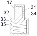
As shown in fig. 2 and 4, the array of supporting legs 3 on the conveying plate 2 is distributed on the conveying plate 2, preferably 5 rows and 5 columns, the thimble 31 of the supporting leg 3 is provided with a buffer cap 17 for preventing scratching the substrate, the substrate fixing clips 4 are respectively arranged at the middle positions of four sides of the conveying plate 2, so that the substrate can be more stably fixed, it is noted that, in order to realize the purpose of using for substrates with different sizes, an interval adjusting mechanism for adjusting the interval between the substrate fixing clips 4 can be arranged between the lower end of the substrate fixing clip 4 and the conveying plate 2, the interval adjusting mechanism can be selected from linear motors,
as shown in FIG. 4, the supporting foot 3 of the present invention comprises a housing 32, an inverted T-shaped thimble 31 disposed in the housing 32, a hole 34 with a diameter smaller than the lower end flange 33 of the thimble 31 is opened at the upper end of the housing 32, and a spring 35 is disposed between the thimble 31 and the inner cavity of the housing 32.
As shown in fig. 3, the substrate fixing clip 4 includes a first driving unit 41 and a plastic clamping plate 42, specifically, a support 22 is disposed on the conveying plate 2, the supports 22 are respectively disposed at the edges of the conveying plate 2, the support 22 includes two oppositely disposed plate bodies 23, shaft holes 24 are respectively disposed on the plate bodies 23, two ends of the plastic clamping plate 42 are connected to the shaft holes 24 on the plate bodies 23 through rotating shafts, the first driving unit 41 is disposed between the two plate bodies 23, and the first driving unit 41 drives the plastic clamping plate 42 to fix the substrate 27 placed on the conveying plate 2; the first driving unit 41 is an air cylinder, a cylinder body of the first driving unit 41 is fixed on the conveying plate 2, a piston rod of the first driving unit 41 is hinged to the rear end of the plastic clamping plate 42 (i.e. the plastic clamping plate 42 is located on the side opposite to the edge of the same side of the conveying plate 2), so that the plastic clamping plate 42 is controlled, and the front end of the plastic clamping plate 42 is pressed on the base plate 27 (shown in fig. 1 and 2), so that the base plate 27 is fixed.
As shown in fig. 1, the present invention further includes a controller 25 and an electric box 26, wherein the controller 25 controls the first driving unit 41 and the second driving unit 11, and the electric box 26 supplies power thereto.
The working principle of the invention is as follows: for convenience of understanding, the two conveying mechanisms 1 are respectively defined as a first conveying mechanism, a second conveying mechanism, and a conveying plate arranged on the first conveying mechanism is a first conveying plate, a conveying plate arranged on the second conveying mechanism is a second conveying plate, and the conveying mechanisms are arranged between the first equipment and the second equipment.
Lifting the first conveying mechanism to enable the two conveying mechanisms to be not on the same plane, wherein a substrate fixing clamp of a first conveying plate on the first conveying mechanism is opened (shown in figure 3), an ejector pin of a supporting leg is in a jacking state at the moment, a substrate is placed in the first conveying mechanism, the weight of the substrate enables the ejector pin of the supporting leg to descend, a substrate fixing frame is closed (shown in figure 2) at the same time, the substrate is fixed, the first conveying mechanism conveys the first conveying plate from first equipment to second equipment, the substrate fixing clamp on the first conveying plate is opened, and the substrate is taken away;
and secondly, after the second conveying mechanism conveys the second conveying plate from the second equipment to the first equipment, the second conveying mechanism ascends, the first conveying mechanism descends, and then the first step is repeated to carry out circulating conveying.
While the invention has been shown and described with reference to certain embodiments, those skilled in the art will understand that: various changes in form and details may be made therein without departing from the spirit and scope of the invention as defined by the appended claims and their equivalents.
Claims (5)
1. A conveyor apparatus, characterized by: the device comprises at least one conveying mechanism (1), wherein a conveying plate (2) is arranged on the conveying mechanism (1), a lifting supporting leg (3) and a substrate fixing clamp (4) arranged on the periphery of the conveying plate (2) are arranged on the conveying plate (2), and a distance adjusting mechanism for adjusting the distance between the substrate fixing clamps (4) is arranged between the lower end of the substrate fixing clamp (4) and the conveying plate (2); the conveying mechanism (1) comprises a second driving unit (11) and a transmission mechanism (12), wherein the second driving unit (11) drives the transmission mechanism (12) to realize the movement of the transmission plate (2); the second driving unit (11) is a servo motor, the transmission mechanism (12) comprises a rack (13) and a gear (14), the rack (13) is fixed on the lifting mechanism (21) through a fixing plate (15), an output shaft of the second driving unit (11) is connected with the gear (14), the gear (14) is meshed with the rack (13), and the conveying plate (2) is fixed on the second driving unit (11); the conveying mechanisms (1) are arranged in pairs and are respectively oppositely arranged, the two conveying mechanisms (1) are respectively provided with a lifting mechanism (21), the two conveying mechanisms (1) are lifted, and the conveying plate (2) is arranged between the two conveying mechanisms (1).
2. The delivery device of claim 1, wherein: the supporting legs (3) are elastic retractable spring thimbles.
3. The delivery device of claim 1, wherein: the substrate fixing clamp (4) comprises a first driving unit (41) and a plastic clamping plate (42), and the first driving unit (41) drives the plastic clamping plate (42) to fix the substrate placed on the conveying plate (2).
4. The conveying apparatus according to any one of claims 1 to 3, wherein: and a guide rail (16) parallel to the rack (13) is arranged on the fixed plate (15), and a sliding block of the guide rail (16) is fixedly connected with the second driving unit (11).
5. The delivery device of claim 2, wherein: the thimble of the supporting leg (3) is provided with a buffer sleeve (17).
Priority Applications (1)
| Application Number | Priority Date | Filing Date | Title |
|---|---|---|---|
| CN201710660890.2A CN107685978B (en) | 2017-08-04 | 2017-08-04 | Conveying device |
Applications Claiming Priority (1)
| Application Number | Priority Date | Filing Date | Title |
|---|---|---|---|
| CN201710660890.2A CN107685978B (en) | 2017-08-04 | 2017-08-04 | Conveying device |
Publications (2)
| Publication Number | Publication Date |
|---|---|
| CN107685978A CN107685978A (en) | 2018-02-13 |
| CN107685978B true CN107685978B (en) | 2020-09-01 |
Family
ID=61153234
Family Applications (1)
| Application Number | Title | Priority Date | Filing Date |
|---|---|---|---|
| CN201710660890.2A Active CN107685978B (en) | 2017-08-04 | 2017-08-04 | Conveying device |
Country Status (1)
| Country | Link |
|---|---|
| CN (1) | CN107685978B (en) |
Families Citing this family (3)
| Publication number | Priority date | Publication date | Assignee | Title |
|---|---|---|---|---|
| CN109590174A (en) * | 2018-11-29 | 2019-04-09 | 东莞华贝电子科技有限公司 | Shuttle type feeding device |
| CN112122195A (en) * | 2019-02-28 | 2020-12-25 | 南京涵铭置智能科技有限公司 | Vertical cleaning device and cleaning method thereof |
| CN111620062A (en) * | 2020-07-31 | 2020-09-04 | 苏州鼎纳自动化技术有限公司 | Large-area workpiece multilayer transmission device and detection or processing method thereof |
Family Cites Families (6)
| Publication number | Priority date | Publication date | Assignee | Title |
|---|---|---|---|---|
| CN201060862Y (en) * | 2007-06-29 | 2008-05-14 | 格兰达技术(深圳)有限公司 | Faulty goods acquisition and salable product complement device for full-automatic tray IC marking machine |
| CN102826348B (en) * | 2012-08-10 | 2016-02-03 | 昆山市和博电子科技有限公司 | A kind of single track double mechanical arms mobile device |
| CN105083980B (en) * | 2015-06-10 | 2017-12-01 | 合肥京东方光电科技有限公司 | Sputtering equipment and its substrate bearing device |
| CN105600447B (en) * | 2016-01-26 | 2018-07-13 | 深圳市华星光电技术有限公司 | Substrate shifting apparatus |
| CN106742687A (en) * | 2016-12-16 | 2017-05-31 | 无锡市汤成机电配件厂 | Glass plate fixed seat |
| CN106829475A (en) * | 2017-02-20 | 2017-06-13 | 东旭科技集团有限公司 | Glass substrate transmission equipment |
-
2017
- 2017-08-04 CN CN201710660890.2A patent/CN107685978B/en active Active
Also Published As
| Publication number | Publication date |
|---|---|
| CN107685978A (en) | 2018-02-13 |
Similar Documents
| Publication | Publication Date | Title |
|---|---|---|
| CN106144473B (en) | A kind of manipulator positions grasping mechanism | |
| CN104960326A (en) | Full-automatic glass panel printing machine | |
| CN107685978B (en) | Conveying device | |
| CN204977749U (en) | Full -automatic glass panels printing machine | |
| CN206050806U (en) | A kind of mechanical hand positions grasping mechanism | |
| CN110841929B (en) | Turntable type watch glass lens detector | |
| CN106516683B (en) | Material transferring transfer system | |
| CN214878160U (en) | Step-by-step conveyor is lifted to axle housing | |
| CN111250449B (en) | Assembly line equipment for automatically cleaning workpiece and dust-free treatment method for workpiece surface | |
| KR101663648B1 (en) | Turnover apparatus for measuring flexible display panel | |
| CN209104131U (en) | A kind of wafer locating unit | |
| CN207271726U (en) | Surface cleaning apparatus | |
| KR20070028025A (en) | Panel transferring lifter | |
| CN214326489U (en) | Photovoltaic glass loading attachment | |
| CN219636340U (en) | Automatic feeding mechanism for optical lens | |
| CN210102916U (en) | Glass substrate carrying device | |
| CN213474719U (en) | Cell-phone glass charging equipment | |
| KR100354103B1 (en) | Panel Sending Apparatus of Liquid Crystal Display Panel Inspection System | |
| CN109592407B (en) | PCB board self-cleaning and check out test set | |
| CN112378926A (en) | Flexible film visual detection device and method | |
| KR100358704B1 (en) | Panel Supplying Apparatus of Liquid Crystal Display Panel System | |
| CN220925474U (en) | Alignment and centering device | |
| CN214879886U (en) | Glass processing equipment and lifting device thereof | |
| CN115676384B (en) | Detection stacking equipment for manufacturing printed circuit board | |
| CN214794407U (en) | Novel automatic visual detection mechanism |
Legal Events
| Date | Code | Title | Description |
|---|---|---|---|
| PB01 | Publication | ||
| PB01 | Publication | ||
| SE01 | Entry into force of request for substantive examination | ||
| SE01 | Entry into force of request for substantive examination | ||
| GR01 | Patent grant | ||
| GR01 | Patent grant |