CN1076308C - Sucktion device - Google Patents
Sucktion device Download PDFInfo
- Publication number
- CN1076308C CN1076308C CN96122407A CN96122407A CN1076308C CN 1076308 C CN1076308 C CN 1076308C CN 96122407 A CN96122407 A CN 96122407A CN 96122407 A CN96122407 A CN 96122407A CN 1076308 C CN1076308 C CN 1076308C
- Authority
- CN
- China
- Prior art keywords
- piston
- cylinder
- liquid
- aspirator
- guiding channel
- Prior art date
- Legal status (The legal status is an assumption and is not a legal conclusion. Google has not performed a legal analysis and makes no representation as to the accuracy of the status listed.)
- Expired - Fee Related
Links
Images


Classifications
-
- B—PERFORMING OPERATIONS; TRANSPORTING
- B05—SPRAYING OR ATOMISING IN GENERAL; APPLYING FLUENT MATERIALS TO SURFACES, IN GENERAL
- B05B—SPRAYING APPARATUS; ATOMISING APPARATUS; NOZZLES
- B05B11/00—Single-unit hand-held apparatus in which flow of contents is produced by the muscular force of the operator at the moment of use
- B05B11/01—Single-unit hand-held apparatus in which flow of contents is produced by the muscular force of the operator at the moment of use characterised by the means producing the flow
- B05B11/10—Pump arrangements for transferring the contents from the container to a pump chamber by a sucking effect and forcing the contents out through the dispensing nozzle
- B05B11/1042—Components or details
- B05B11/1073—Springs
- B05B11/1078—Vacuum chambers acting like springs
-
- B—PERFORMING OPERATIONS; TRANSPORTING
- B05—SPRAYING OR ATOMISING IN GENERAL; APPLYING FLUENT MATERIALS TO SURFACES, IN GENERAL
- B05B—SPRAYING APPARATUS; ATOMISING APPARATUS; NOZZLES
- B05B11/00—Single-unit hand-held apparatus in which flow of contents is produced by the muscular force of the operator at the moment of use
- B05B11/01—Single-unit hand-held apparatus in which flow of contents is produced by the muscular force of the operator at the moment of use characterised by the means producing the flow
- B05B11/10—Pump arrangements for transferring the contents from the container to a pump chamber by a sucking effect and forcing the contents out through the dispensing nozzle
- B05B11/1001—Piston pumps
-
- B—PERFORMING OPERATIONS; TRANSPORTING
- B05—SPRAYING OR ATOMISING IN GENERAL; APPLYING FLUENT MATERIALS TO SURFACES, IN GENERAL
- B05B—SPRAYING APPARATUS; ATOMISING APPARATUS; NOZZLES
- B05B11/00—Single-unit hand-held apparatus in which flow of contents is produced by the muscular force of the operator at the moment of use
- B05B11/01—Single-unit hand-held apparatus in which flow of contents is produced by the muscular force of the operator at the moment of use characterised by the means producing the flow
- B05B11/10—Pump arrangements for transferring the contents from the container to a pump chamber by a sucking effect and forcing the contents out through the dispensing nozzle
- B05B11/1097—Pump arrangements for transferring the contents from the container to a pump chamber by a sucking effect and forcing the contents out through the dispensing nozzle with means for sucking back the liquid or other fluent material in the nozzle after a dispensing stroke
-
- B—PERFORMING OPERATIONS; TRANSPORTING
- B05—SPRAYING OR ATOMISING IN GENERAL; APPLYING FLUENT MATERIALS TO SURFACES, IN GENERAL
- B05B—SPRAYING APPARATUS; ATOMISING APPARATUS; NOZZLES
- B05B11/00—Single-unit hand-held apparatus in which flow of contents is produced by the muscular force of the operator at the moment of use
- B05B11/0005—Components or details
- B05B11/0037—Containers
- B05B11/0039—Containers associated with means for compensating the pressure difference between the ambient pressure and the pressure inside the container, e.g. pressure relief means
- B05B11/0044—Containers associated with means for compensating the pressure difference between the ambient pressure and the pressure inside the container, e.g. pressure relief means compensating underpressure by ingress of atmospheric air into the container, i.e. with venting means
Abstract
In a pump mechanism attached to a container to fill a liquid and eject the liquid from the container, the pump mechanism includes: a cylinder having a liquid introduction port; a piston which is displaceable in the cylinder; an ejection guide path for the liquid, the path being communicated with the space in the cylinder, the liquid stored in the cylinder being ejected via the ejection guide path by a pushing force which causes the piston to be displaced from the original position to a displaced position; and a recovery device for restoring the piston from the displaced position to the original position by a gas pressure and storing the liquid in the cylinder when the pushing force is released. With the pump mechanism, when it is to be subjected to a disposal process or a recycle process, it is not required to conduct selection according to the material and which can be therefore subjected to such a process at a low cost.
Description
The present invention relates to the aspirator on a kind of container that is installed in full of liquid (such as the soap lye of washing one's hands, shampoo, rinsing liquid), it is pumping liquid from container, and the liquid that then these is aspirated is up discharged.
Recently because easy to use, the sort of have press the liquid supplying apparatus that just can discharge the appropriate amount of fluid structure and be widely used.In this device, the parts of particular importance are to aspirate the aspirator that is stored in the liquid in the container and discharges certain quantity of fluid.
Referring to Fig. 9 and Figure 10, will be described the structure of the aspirator in the prior art below.Fig. 9 is the semisectional view under the state of aspirator before discharged liquid, and Figure 10 is the semisectional view of aspirator under the state behind the discharged liquid.
In Fig. 9 and Figure 10, lid shape base component 31 is spun on the opening of container (expression in the drawings) of full of liquid.Cylinder 32 is fixed on the base component 31.Ball valve 33 is arranged on the lower end of cylinder 32.A pipe (not expression in the drawings) that is used for through ball valve 33 pumping liquids links to each other with cylinder 32.The lower end of quill shaft 34 has a cup type piston 34a.The inner headed face closed contact of the periphery of piston 34a and cylinder 32.
Cap 35 and the nozzle 36 that fuses is housed in the upper end of axle 34.One ball valve 37 is arranged on the position of close cap 35 on the axle 34.
Between cylinder 32 and axle 34, a coil spring that is made of metal 38 is housed.Guide 39 is set makes coil spring 38 can't be bent into L shaped but can vertical stretching and compression.Another effect of guide 39 is the moving range that limits the ball of forming ball valve 33 as block.
In the aspirator of this structure, when liquid holdup (state shown in Figure 9) when depressing cap 39 under the state of cylinder 32 is being arranged, fluid pressure raises and has only ball valve 37 to open, and liquid is discharged from nozzle 36 like this.
When unclamping cap 35 under the state of finishing discharged liquid fully, piston 34a is pushed to the top by helical spring restoring force, and this spring is in compressive state always in the operating process of depressing cap 35.Simultaneously, in cylinder 32, produce negative pressure and have only ball valve 35 to open, so liquid is inhaled people's cylinder 32 and set up a kind of ejection readiness.
When the aspirator of this prior art was handled or reclaimed, before carrying out this processing, kinds of materials (such as resin and metal) must be separated from each other.In case this aspirator of hand disassembly particularly, the coil spring 38 that is made of metal should disassemble from the container body that resin is made.Therefore disposal cost is very high.
When this aspirator of long-time use,, may produce trouble because the performance of coil spring 38 reduces.Particularly thereby coil spring 38 often is immersed in the liquid and gets rusty easily.This can cause reducing of spring force or make spring breakage.When this influence produced, coil spring 38 can't apply required elastic reaction, so piston 34a can't return to original position.Consequence is to spray liquid again.
Except that the problems referred to above, the aspirator in the prior art also has other problem.That is to say,, be badly in need of reducing the size of aspirator and simplifying its structure in order to reduce raw-material consumption aborning and to effectively utilize resource.
Aspirator also has following problem: the restoring force numerical value of piston 34a must be according to the kind relative set of liquid.For example when having full-bodied colloidal liquid need handle the time, restoring force numerical value must be provided with highly.This is poor because have the flowing power of full-bodied liquid, and piston 34a must promote at a relatively high speed, so that the negative pressure that produces in the cylinder 32 is than the pressure height under the common fluid situation.According to this point, in prior art, need to replace have different elastic forces, be that the coil spring 38 of different elasticity moduluss is adjusted elastic force.Therefore, need to prepare to have the multiple coil spring of different elasticity moduluss, this has just increased cost of production.
In order to address these problems, the present invention has been proposed.Main purpose of the present invention provides a kind of aspirator, when it is handled or reclaims, needn't select according to material again, thereby can carry out above-mentioned processing to aspirator under low cost.
Second purpose of the present invention provides a kind of aspirator, and it is durable in use, even after using for a long time, also be difficult for producing operation failure, and simple in structure or number of parts is few.
The 3rd purpose of the present invention provides a kind of aspirator, antagonistic force or restoring force that it produces in the time of easily changing discharged liquid, thus be suitable for various liquid.
Can achieve the above object by following aspirator.This aspirator is contained on the container of a full of liquid, and sprays liquid from container, and it comprises: one has the cylinder that liquid is led population; The piston that can in cylinder, move; Article one, liquid is discharged guiding channel, and this passage links to each other with space in the cylinder, makes piston move to the another location from the initial position under thrust, thereby the liquid that is stored in the cylinder is sprayed through discharging guiding channel; And when discharging thrust by make the recovery position of the location restore of piston after moving storaging liquid and cylinder by the gaseous tension that thrust produced to the initial position.
In the aspirator of form, aspirator also comprises in of the present invention first: the lid shape base component that cooperates with container for cylinder is installed is shaped on a through hole in the central authorities of this base component; One is positioned at liquid leads near first valve of population, and it makes liquid only pass through this first valve on the direction from the container to the cylinder; Near second valve that is positioned at the discharge guiding channel, it makes liquid only pass through this second valve on the direction from the cylinder to the liquid outlet; One is shaped on the discharge guiding channel by foot guide and from the axle that piston stretches out on the axle, and piston can move by axle.Thrust makes the space in the piston almost be vacuum state, and gaseous tension is produced by the internal pressure in this space with by the pressure reduction of liquid effects between the bar pressure on the piston.
Aspirator of the present invention second in the form, aspirator also comprises: the lid shape base component that cooperates with container for cylinder is installed is shaped on a through hole in the central authorities of this base component; Near first valve that is positioned at the liquid introducing port, it makes liquid only pass through this first valve on the direction from the container to the cylinder; Near second valve that is positioned at the discharge guiding channel, it makes liquid only pass through this second valve on the direction from the cylinder to the liquid outlet; One is shaped on the discharge guiding channel by foot guide and from the axle that piston stretches out on the axle, and piston can move by axle.This aspirator comprise the gassiness chamber that is arranged in pedestal and one can gassiness chamber move and with the auxiliary piston of piston interlock, gaseous tension is produced by the pressure of the gas that is compressed in gassiness chamber by auxiliary piston.
In second kind of form, preferably cylindraceous from the axle that piston stretches out, with the cooresponding piston of axle on be shaped on a through hole, axle is at least as a part of discharging guiding channel.When adopting this structure, the structure of aspirator is further simplified.
In the 3rd form of aspirator of the present invention, aspirator also comprises: the lid shape base component that cooperates with container for cylinder is installed is shaped on a through hole in the central authorities of this base component; First cylinder that is positioned on the base component is shaped on a liquid return hole on the periphery of this first cylinder; Bottom surface one side from first cylinder is extended and is had second cylinder that liquid is led population; Near first valve that is positioned at the liquid introducing port, it can allow liquid only the direction from container to second cylinder by first valve; The first piston that also can move in first cylinder ringwise is shaped on first through hole at the center of first piston; A primary shaft that stretches out from first piston comprises first liquid reflux channel of discharging guiding channel and extending along roughly parallel with first discharge guiding channel direction with first through hole cooresponding first on it; Second piston that also can move in second cylinder ringwise is shaped on second through hole at the center of second piston, under thrust, causes that second piston moves, thereby forms the space that is roughly vacuum between second piston and the first cylinder bottom surface; Second of stretching out from second piston, it comprises corresponding with second through hole and discharges the second discharge guiding channel that guiding channel extends from first, second by the first cylinder bottom surface and airtight with its maintenance, and second couples together the first piston and second piston; An outlet device that is contained on the primary shaft, this outlet device comprise from first discharge that guiding channel extends the 3rd discharge guiding channel with from the 3rd second discharge guiding channel of discharging guiding channel top set and linking to each other with first liquid reflux channel; Second valve between primary shaft and outlet device, under the effect of thrust, because moving of first and second pistons, the liquid that is stored in second cylinder is only discharged the guiding channel by the first and the 3rd in the direction from second cylinder to the outlet device opening, and under the recovery device effect, when first and second pistons return to their original position, second valve be retained in the 3rd discharge in the guiding channel liquid only the direction from outlet device to first cylinder discharge the guiding channels by first and second.
In the aspirator of the 3rd form, the bottom surface that is preferably in first cylinder is shaped on second annular protrusion that can pass wherein, on the inner headed face of projection, make circular groove, making a groove near on second position of piston on second periphery around second.
Adopting this structure is for when the space between the lower surface of upper surface that makes second piston in air admission second cylinder because of certain reason and annular projection, can easily air be discharged to the outside.In having the aspirator of this structure, particularly during the upper taller position when second piston rises to than common use, in uphill process, second the groove and the circular groove of annular projection meet, formed one from groove through circular groove to exhaust passage that first cylinder extends.Therefore, the air that advances people's second cylinder can easily be arranged to first cylinder.When carrying out this operation periodically, the inside of second cylinder just can keep required degree of vacuum, and the performance of aspirator just can not reduce like this.Can adopt the aspirator of this structure to be limited only following situation in theory, the space that promptly roughly is vacuum therein always forms between the lower surface of the upper surface of second piston and annular projection.In having the aspirator of other structure, such as if the lower surface of the upper surface of second piston and annular projection closed contact mutually always wherein then needn't carry out bleeding, so needn't adopt said structure.
As mentioned above, in aspirator of the present invention, because the pressure of bar pressure and pressure gas or roughly be between the internal pressure in space of vacuum state and have pressure reduction can make piston reset, so do not need coil spring.Substituting the employed recovery device of coil spring can make with the resin material identical with the aspirator body.Metal helical spring aspirator is different with using, and when aspirator was handled or reclaimed, aspirator of the present invention need not dismantled and separate, so disposal cost reduces.
Because do not have use easily because of liquid causes the metal coil spring that gets rusty, even use for a long time, aspirator can not lose efficacy yet, so this device has good durability.
In addition, except coil spring, also can save guide element.Like this, the space in the cylinder just can more effectively be utilized, and can reduce height (along the size of piston moving direction).The result is that the size of aspirator has reduced.In addition, because saved coil spring and guide element, number of parts has also reduced, thereby simplifies the structure.
In aspirator of the present invention, the antagonistic force that produces when depressing piston (restoring force) can be by changing the original position setting of piston with respect to cylinder, that is, adjust arbitrarily by the amount of air that change is retained under the initial conditions in the cylinder.For example, when piston is arranged on roughly near the lid place of installing on the container (having at aspirator under the situation of two cylinders, near the place, bottom surface of another cylinder), almost there is not air residual.Under this structure, borrow thrust that piston is moved after, can in cylinder, form the space that is roughly vacuum at once.Under this condition, it is maximum that the internal pressure of cylinder and the difference of pressure between bar pressure reach, thereby form maximum restoring force.On the contrary, when in the cylinder during residual a certain amount of air, even when piston is depressed, internal pressure can suddenly not reduce yet, so restoring force is less.From the above description as can be seen, in suction of the present invention, by what change piston the such simple operations in position is set, the restoring force numerical value of piston can suitably be set according to the kind of liquid, therefore, different with the helical spring suction of use, this aspirator can not increase cost of production.
The aspirator of working as of the present invention not only can be used for hand by the type aspirator, also can be used for so-called triggering and distributes the type aspirator.Particularly aspirator can be configured to following form: promptly the power that is applied by the distributing box that handled by pointer or analogue directly or indirectly acts on the axle (or piston itself) that extends on the piston; Thereby liquid is discharged from nozzle.
Fig. 1 is the cutaway view under the state of aspirator (first embodiment) before discharged liquid;
Fig. 2 is the cutaway view of aspirator (first embodiment) under the state behind the discharged liquid;
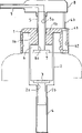
Fig. 3 is the cutaway view under the state of aspirator (second embodiment) before discharged liquid;
Fig. 4 is the cutaway view of aspirator (second embodiment) under the state behind the discharged liquid;
Fig. 5 is the cutaway view under the state of aspirator (the 3rd embodiment) before discharged liquid;
Fig. 6 is the cutaway view of aspirator (the 3rd embodiment) under the state behind the discharged liquid;
Fig. 7 is the cutaway view that is illustrated under the state that forms air discharging channel;
Fig. 8 is the cutaway view that is illustrated in order to recover restoring force under the air state of temporarily discharging in the vacuum chamber;
Fig. 9 is the semisectional view under the state of aspirator before discharged liquid in the prior art;
Figure 10 is the semisectional view of aspirator under the state behind the discharged liquid in the prior art;
Below with reference to accompanying drawings embodiments of the invention are specifically described.
Fig. 1 and Fig. 2 have represented the first embodiment of the present invention.Wherein be provided with and cover shape base component 1, to enable the opening part of its container that is spun on full of liquid (representing) with long and short dash line.On the inner peripheral surface of base component, be shaped on thread groove.Be shaped on cylindrical protrusion (lid) 1a with its formation one in the back side of base component 1 central authorities.Being shaped on one on projection 1a is used for induce one aperture 1b in the container of barometric pressure.Cylinder 2 assemblings also are fixed on the projection 1a.In order to prevent the inside of air admission cylinder 2, between cylinder and projection, be formed with good being connected of air-tightness.
On the cylinder bottom surface, be shaped on liquid and lead population 2a, three-point suspension valve (first valve) 3 is housed on it.A pipe 4 that is used for liquid in the aspiration container links to each other with the conduit 2b that leads population 2a extension from liquid.
Have in the quill shaft 5 and discharge guiding channel 5a.Above-mentioned axle passes the projection 1a of base component 1 and by its guiding, is in airtight conditions between the two.
Be provided with a piston 6 and the inner headed face closed contact of the periphery of piston 6 and cylinder 2 in the lower end of axle 5.In other words, when the inside of cylinder 2 kept airtight, piston 6 was movably.
Three-point suspension valve (second valve) 7 is housed with corresponding through hole 6a on the bottom surface of piston 6.
Nozzle 9 is made one with valve protection cap 8.
In the aspirator of this structure, (state shown in Figure 1) depresses container cap 8 when leaving liquid in cylinder 2, and the pressure of liquid raises, and makes three-point suspension valve 7 open (three-point suspension valve 3 cuts out at this moment).The three-point suspension valve 7 of liquid by opening, then finally ejection from nozzle 9 by discharging guiding channel 5a.
Simultaneously, between the lower surface of the upper surface of piston 6 and projection 1a, formed the space B that is roughly vacuum.Then, the lifting masterpiece that produces of the pressure reduction between the internal pressure of bar pressure by liquid effects and space B is used on the piston 6.That is to say, produced the effect opposite reaction of the power downward with promoting cap 8.Piston 6 is depressed manyly more, and it is many more that the numerical value of antagonistic force increases.
When cap 8 overcomes antagonistic force and the certain quantity of fluid that is forced into final position and corresponding single job when being sprayed cylinder 2 fully, just formed state shown in Figure 2.
In this state, after the power on the cap 8 of being applied to discharged, because barometric pressure and be roughly differential pressure action between the space B internal pressure of vacuum, piston 6 was above being pushed under the restoring force effect.This makes three-point suspension valve 3 open (this moment three-point suspension valve 7 close) liquid is sucked in the cylinder 2.When piston 6 turned back in position before it extrudes liquid and the cylinder 2 full of liquid, the sort of readiness that can spray liquid was set up once more.
As mentioned above, in first embodiment of the invention, by bar pressure and be roughly the pressure reduction between the space B internal pressure of vacuum and the power that produces as the recovery device of piston 6.Therefore, do not need metal coil spring.When aspirator being handled or during recovery process, needn't be selected according to material again, thereby can under low cost, carry out above-mentioned processing to aspirator.
The helical spring aspirator of metallic is different with using, and can avoid the operation failure that causes owing to getting rusty and stably show long-term discharge opeing ability such as the aspirator among the present invention.
In addition, owing to cut down metal coil spring and guide, can utilize the space in the cylinder and can reduce its height by actv..In addition, compare with the aspirator of prior art, number of parts has reduced, thereby makes designs simplification according to the minimizing of this number of parts.
Fig. 3 and Fig. 4 have represented the second embodiment of the present invention.
This embodiment and the first embodiment difference are to be provided with auxiliary piston 41, so that it can move constituting in the chamber that is full of air (gassiness chamber) 42 of one with base component 1 when keeping airtight.The chamber 42 that is full of air has replaced the space B among first embodiment.Other structure of second embodiment is identical with first embodiment.Therefore, corresponding parts are represented with identical sequence number and have been omitted description of them.
The aspirator of this structure is operated in the following manner.When (state shown in Figure 3) under the state that in cylinder 2, leaves liquid with under the hand during cap 8, the fluid pressure in the cylinder 2 raises, and the three-point suspension valve is opened, liquid is by discharging guiding channel 5a and spraying from nozzle 9 like this.When cap 8 resistant functions on auxiliary piston 41 antagonistic force and be forced into the final position and liquid when being sprayed fully, just formed state shown in Figure 4.In this state, after unclamping cap 8, auxiliary piston 41 is lifted under the compressed-air actuated effect in the chamber 42 that is full of air, and along with the mobile piston 6 of auxiliary piston also and then rises.At this moment, have only three-point suspension valve 3 to open, liquid is inhaled in people's cylinder 2 like this.At last, piston 6 turns back to full of liquid in original position and the cylinder 2, thereby sets up the sort of readiness that can spray liquid once more.
As mentioned above, in the described aspirator of second embodiment, air pressure is used as recovery device.Therefore, do not need metal coil spring, and this aspirator can reach the effect identical with first embodiment.
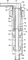
Fig. 5 to Fig. 8 has represented third embodiment of the invention.
On the bottom surface of second cylinder 12, be shaped on liquid and lead population 12a.Three-point suspension valve (first valve) 14 is housed on that position.One is used for the pipe of pumping liquid from container (expression in the drawings) and leads the guide wire 12b that population 12a extends from liquid and link to each other.
Have first in first axle 15 and discharge guiding channel 15a, above-mentioned axle also can be moved in vertical direction by base component 10 guiding.
The first piston 16 that has a through hole that extends from the first guiding channel 15a constitutes one with the end portion of primary shaft 15.The inner headed face closed contact of the periphery of first piston 16 and first cylinder 11, when the 11 inner maintenances of first cylinder were airtight, first piston just can move like this.
In primary shaft 15, except the first discharge guiding channel 15a, also be shaped on the first liquid return road 15b.The first liquid return road 15b is by first piston 16.
Have second in second 17 and discharge guiding channel 17a, and pass through the bottom surface of first cylinder 11, that is,, and keep airtight by annular protrusion 13.Make first and second to discharge guiding channel 15a and continuous discharge guiding channel of 17a formation in the primary shaft 15 thereby be installed into for second 17.
Have second piston 18 and second 17 end portion formation one of discharging the through hole of guiding channel 17a from second.First and second pistons 16 and 18 interconnect so that interlock mutually by second 17.
Cap (outlet device) 20 constitutes one with nozzle 19.Cap 20 is installed on the primary shaft 15, is provided with valve (second valve) 21 therebetween, and valve 21 cross sectional shapes are disk-shaped and have identical directivity with three-point suspension valve 14.Although not special expression, valve 21 middle parts promptly with first opposed area of discharging the opening part of guiding channel 15a, are formed with the linear slit, except the part of device, stick on the cap 20 around the marginal portion of slit.
Second liquid reflux channel 22 is from flow passage (the 3rd escape route) bifurcated of cap 20.In valve 21, the part that adheres to cap 20 is not the adjacent domain with the second liquid return road, 22 cooresponding these parts of partial sum.When cap 20 turned back to original position after liquid is discharged, under the negative pressure that produces in first cylinder 11, the non-adhesion section of valve 21 was sucked and is out of shape.This causes the opening in the second liquid return road 22 closed by valve 21 to be opened.Then be retained in liquid in the nozzle 19 from the slit that forms by valve 21 distortion to dirty, and be sucked into first cylinder 11 by the first liquid return road 15b.
On the inner headed face that is positioned at the projection 13 on first cylinder, 11 bottom surfaces, be shaped on one around second 17 circular groove 23.Second 17 periphery is shaped on groove 24, and it is positioned near second piston 18.As mentioned below, circular groove 23 and groove 24 are used for bleeding to keep required degree of vacuum.
On the inner headed face of the center through hole of base component 10, make spline 25 with predetermined space.To make spline 26 with spline 25 corresponding intervals, therefore, when depressing primary shaft 15 after keyway is aimed at, spline 26 can be by being shaped on the position of spline 25 at spline on the periphery of primary shaft 15.After this, primary shaft 15 can rotate slightly and make spline 26 block spline 25.Therefore, even then discharge thrust, primary shaft 15 can not be pushed again and get back to original position.In this manner, primary shaft 15 is subjected to spacing usually and is pulled to position shown in Figure 5.
Be still the aspirator with said structure, as liquid holdup (state shown in Figure 5) when depressing cap 20 under the state of the lower space of second cylinder 12, fluid pressure raises and valve 21 opens (this moment three-point suspension valve 14 keep cutting out).Valve 21 and then from nozzle 19 ejection of liquid by opening.
Simultaneously, the step-down operation of first piston 16 is discharged the liquid (a certain amount of withdrawing fluid) in the cylinder 11 of winning from through hole 11a, so liquid is expelled back in the container.
When second piston 18 descended in the discharge opeing operation, the space between the lower surface of piston upper surface and annular protrusion 13 increased.Then, by the pressure reduction between the internal pressure of the upper space (vacuum chamber) of the bar pressure and second cylinder 12 and the lifting masterpiece that produces be used on second piston 18.This masterpiece is the power that cap 20 is depressed in antagonistic force (restoring force) opposing.When cap 20 overcomes antagonistic force and the certain quantity of fluid that is pressed downwardly onto final position and corresponding single job when being ejected, just formed state shown in Figure 6.
After the liquid ejection, the power that is applied on the cap 20 is released.Then second piston 18 is lifted to original position under the effect of restoring force.This makes three-point suspension valve 14 open (this moment, valve 21 maintenances were closed), thereby makes liquid be sucked into the lower space of second cylinder 12.
When second piston 18 rose, first piston 16 also rose, and has therefore produced negative pressure in first cylinder 11.Then the non-adhesion section of valve 21 is sucked and is out of shape and makes the liquid that is not discharged from and is trapped in the nozzle 19 pass through valve.Those liquid by valve 21 then are sucked into first cylinder 11 by the first liquid return road 15b.Thereby stoped liquid to ooze from the end of nozzle 19.
When second piston 18 turns back in ejection liquid secondary piston residing position, or when turning back to state shown in Figure 5, the lower space full of liquid of second cylinder 12, the sort of readiness that can spray liquid is set up once more.
In having the aspirator of said structure, air may advance the upper space (space between the lower surface of the upper surface of second piston 18 and annular protrusion 13) of people's second cylinder 12 for a certain reason.According to this point, the present embodiment structure has the structure that can carry out bleeding.
Carry out bleeding in the following manner.At first, suitably rotate primary shaft 15 to cancel cause by the combination of spline 25 and spline 26 spacing.Upper higher position when this makes cap 20 rise to than common use.
After cap 20 rose, in uphill process, the groove 24 on second 17 ran into the circular groove 23 of annular protrusion 13, has formed the escape route of the air in the upper space that advances people's second cylinder 12 like this, shown in the arrow among Fig. 7.When cap 20 rose and forms state shown in Figure 8, those air that advanced in people's second cylinder 12 were discharged from cylinder fully, thereby have finished bleeding.
For the aspirator of this function is provided, the air-tightness between second 17 and annular protrusion 13 gradually changes.Especially, annular protrusion 13 is divided into first half 13a and lower part 13b by circular groove 23.First half 13a and second 17 s' air-tightness is provided with not too highly.On the contrary, lower part 13b and second 17 s' air-tightness is provided with very highly.As can be seen from Fig. 7, the width d1 of the lower part 13b of annular protrusion 13 is littler than the width d2 of groove 24.
Therefore, owing to there is a groove 24, air is through the lower part 13b people's circular groove 23 of going forward side by side, and then by the space between first half 13a and second 17, row advances first cylinder 11 again.When carrying out regular bleeding, just can keep required degree of vacuum, thereby the performance that prevents aspirator reduces.
As mentioned above, in third embodiment of the invention, by bar pressure and be roughly the pressure reduction between the interior volume pressure of vacuum and the power that produces as the recovery device of first and second pistons 16 and 18.Therefore, do not need metal coil spring.So, when aspirator being handled or during recovery process, needn't be selected according to material again, thereby can under low cost, carry out above-mentioned processing to aspirator.
The helical spring aspirator of metallic is different with using, and can avoid the operation failure that causes owing to getting rusty and stably show long-term discharge opeing ability such as the aspirator among the present invention.
In described aspirator of the 3rd embodiment and the described aspirator of first and second embodiment, can adjust the antagonistic force or the restoring force of cap easily.Generally by selecting to use coil spring to adjust restoring force with the revolution number of turns on different winding diameters or the per unit length.In the aspirator of the embodiment of the invention, can use expensive like this method just can freely adjust restoring force.
When for example having not a particle of air in the upper space that second piston 18 makes second cylinder 12 is set, under the situation of depressing second piston 18, thereby the internal pressure of second cylinder 12 and the pressure reduction between bar pressure will reach the maximum maximum restoring force that forms.On the contrary, when second piston 18 being set to make second cylinder, 12 upper spaces be residual certain air, when depressing piston, internal pressure is not greatly to reduce, so restoring force is less.
In the aspirator of the embodiment of the invention, can adjust restoring force with said method.Therefore, this aspirator can aspirate the different types of liquid with different viscosities at an easy rate.
According to aspirator of the present invention, when it is handled or reclaims, needn't select according to material again, thereby can under low expense, carry out above-mentioned processing aspirator.After using for a long time, this aspirator also is difficult for causing operation failure, and durability is good.In addition, this aspirator can be made into also littler than the device volume in the prior art, and number of parts is few, simple in structure.In this aspirator, the antagonistic force or the restoring force that produce in the time of adjusting liquid at an easy rate and will discharge are so it is applicable to multiple liquid.
Claims (13)
1. the aspirator of ejection liquid on the container that is installed in full of liquid and in the container, described aspirator comprises:
One has liquid introducing port (2a, cylinder 112a) (2,12);
The piston (6,18) that can in described cylinder (2,12), move;
Article one, liquid is discharged guiding channel (5a, 15a, 17a), described passage and described cylinder (2,12) space links to each other, under thrust, described piston (6,18) moves to the another location from initial position, be stored in described cylinder (2 thereby make, 12) (5a, 156a 17a) spray Nei liquid through described discharge guiding channel;
Engage and comprise the base component (1,10) of a through hole with described container;
When discharging thrust, make the location restore of described piston (6,18) after moving to initial position and described cylinder, store the recovery device of liquid by the gaseous tension that produces by thrust;
It is characterized in that, described recovery device comprises owing to described thrust and at described piston (6,18) vacuum of setting up above, described thrust with air tight manner respectively at described base component (1,10) move at least one axle (5,15,17) in and at described cylinder (2,12) interior mobile piston (6,18).
2. aspirator as claimed in claim 1 is characterized in that,
Base component (1) is to cover shape;
One first valve (3) is positioned near the described liquid introducing port (20), and it makes liquid only pass through described first valve (3) in the direction from described container to described cylinder (2);
One second valve (7) is positioned near the described discharge guiding channel (5a), and it makes liquid only pass through described second valve (7) in the direction from described cylinder (2) to a liquid outlet;
Axle (5) stretches out by described base component (1) guiding and from described piston (6), is shaped on described discharge guiding channel (5a) on the axle, and described piston (6) can move by described axle (5).
3. aspirator as claimed in claim 1 or 2, it is characterized in that, a lid (1a), described axle (5) is by described lid and airtight with its maintenance, described lid is closed in the opening that described axle (5) extends the described cylinder (2) of a side, described lid (1a) and described piston (6) form a space (B), under thrust, can form the state that is roughly vacuum in this space, under the action of pressure between the bar pressure on the described piston, produce gaseous tension at the internal pressure of this space (B) with by liquid effects.
4. aspirator as claimed in claim 1 or 2 is characterized in that, described discharge guiding channel (5a) is made of a hole that is formed on the described axle (5), is shaped on a through hole (6a) on the described piston (6) to link to each other with described discharge guiding channel (5a).
5. aspirator as claimed in claim 1 is characterized in that:
Described base component (10) is to cover shape;
Described cylinder is second cylinder (12);
One first cylinder (11) is positioned at described base component (10) and is included in the liquid return hole (11a) that forms on the periphery of described first cylinder (11);
One second cylinder (12) is contained on bottom surface one side of described first cylinder (11) and has described liquid introducing port (12a);
One first valve (14) is positioned near the described liquid introducing port (12a), and it can allow liquid only pass through described first valve (14) in the direction from described container to second cylinder (12);
Described piston is second piston (18);
A first piston (16) ringwise and can in described first cylinder (11), move, and be included in described first piston (16) in one first through hole being formed centrally;
One primary shaft (15) stretches out from described first piston (16), comprise on it with described first through hole cooresponding first and discharge guiding channel (15a), and comprise first liquid reflux channel (15b) that extends with described first discharge guiding channel (15a) almost parallel;
One second piston (18) ringwise and can described second cylinder (12) in, move, and be included in described second piston (18) in one second through hole and the space that is roughly vacuum that are formed centrally by cause that under thrust second piston (18) is mobile and form between described second piston (18) and described first cylinder (11) bottom surface;
Stretch out from described second piston (18) one second (17), it comprises corresponding with described second through hole and discharges the second discharge guiding channel (17a) that guiding channel (15a) extends from described first, described second (17) by described first cylinder (11) bottom surface and airtight with its maintenance, and described first piston (16) and second piston (18) are coupled together;
An outlet device (20) is contained on the described primary shaft (15), and it comprises from the 3rd discharge guiding channel of described first discharge guiding channel (15a) extension with from the described the 3rd second liquid reflux channel (22) of discharging guiding channel top set and joining with described first liquid reflux channel (15b);
One second valve (21) is positioned between described primary shaft (15) and the described outlet device (20), under the effect of thrust, because first and second pistons (16, moving 18), the liquid that is stored in described second cylinder (12) is only discharged the guiding channel by the described first and the 3rd along the direction from described second cylinder (12) to described discharge component openings (20), and under described recovery device effect, when described first and second pistons (16, when 18) returning to their original position, described second valve (21) is only discharged between the guiding liquid reflux channels (15b, 22) liquid that is retained in described the 3rd discharge guiding channel by described first and second along the direction from described outlet device (20) to described first cylinder (11).
6. aspirator as claimed in claim 5 is characterized in that, that described first cylinder (11) is included in is that the bottom surface of described first cylinder (11) forms, described second (17) can pass one of them annular protrusion (11); On the inner headed face of projection, form around described second circular groove (23); An and groove that on the close position of described second piston (18) on described second (17) periphery, forms.
7. the aspirator of ejection liquid on the container that is installed in full of liquid and in the container, described aspirator comprises:
A cylinder (2) that has liquid introducing port (2a);
The piston (6) that can in described cylinder (2), move;
Article one, liquid is discharged guiding channel (5a), described passage links to each other with the space of described cylinder (2), under thrust, described piston (6) moves to the another location from initial position, thereby the liquid that is stored in the described cylinder (2) is sprayed through described discharge guiding channel (5a);
When discharging thrust by the gaseous tension that produces by thrust make the location restore of described piston (6) after moving to initial position and described cylinder (2) the recovery device of storage liquid;
It is characterized in that, described recovery device comprises an auxiliary piston (41), it can move in gassiness chamber (42) and link with described piston (6), and air pressure is by being produced by the pressure of the gas of described auxiliary piston (41) compression in gassiness chamber (42).
8. aspirator as claimed in claim 7 is characterized in that, described gassiness chamber (42) is arranged in the base component (1) that engages with described container.
9. aspirator as claimed in claim 8 is characterized in that, described base component (1) is to cover shape.
10. aspirator as claimed in claim 8 or 9, it is characterized in that, comprise one by described base component (1) guiding and the axle (5) that stretches out from described piston (6), described axle (5) links to each other with the cap of accepting thrust (8), described piston (6) can move by described axle (5), and wherein auxiliary piston (41) is connected to by a bar (43) and is used to make piston (6) and auxiliary piston (41) interlock on the described cap (8).
11. aspirator as claimed in claim 10 is characterized in that, described axle (5) has described discharge guiding channel (5a).
12. aspirator as claimed in claim 11, it is characterized in that, described discharge guiding channel (5a) is made of a hole that is formed on the described axle (5), and described piston (6) has a through hole (6a), and this through hole forms and is connected to described discharge guiding channel (5a).
13. aspirator as claimed in claim 7 is characterized in that, one first valve (3) is positioned near the described liquid introducing port (2a), and makes liquid only pass through described first valve (3) in the direction from described container to described cylinder (12); One second valve (7) is positioned near the described discharge guiding channel (5a), and makes liquid only pass through described second valve in the direction from described cylinder (2) to a liquid outlet.
Applications Claiming Priority (6)
| Application Number | Priority Date | Filing Date | Title |
|---|---|---|---|
| JP23052095 | 1995-09-07 | ||
| JP230520/1995 | 1995-09-07 | ||
| JP230520/95 | 1995-09-07 | ||
| JP93770/96 | 1996-04-16 | ||
| JP93770/1996 | 1996-04-16 | ||
| JP09377096A JP3804691B2 (en) | 1995-09-07 | 1996-04-16 | Pump mechanism |
Publications (2)
| Publication Number | Publication Date |
|---|---|
| CN1159416A CN1159416A (en) | 1997-09-17 |
| CN1076308C true CN1076308C (en) | 2001-12-19 |
Family
ID=26435061
Family Applications (1)
| Application Number | Title | Priority Date | Filing Date |
|---|---|---|---|
| CN96122407A Expired - Fee Related CN1076308C (en) | 1995-09-07 | 1996-09-07 | Sucktion device |
Country Status (7)
| Country | Link |
|---|---|
| US (2) | US5881927A (en) |
| EP (2) | EP0761559B1 (en) |
| JP (1) | JP3804691B2 (en) |
| KR (1) | KR970016111A (en) |
| CN (1) | CN1076308C (en) |
| DE (2) | DE69637330T2 (en) |
| TW (1) | TW312676B (en) |
Families Citing this family (13)
| Publication number | Priority date | Publication date | Assignee | Title |
|---|---|---|---|---|
| US6269981B1 (en) | 1999-12-20 | 2001-08-07 | Reagan Nielsen | Oil dispensing apparatus |
| US7762427B2 (en) * | 2005-06-10 | 2010-07-27 | Kranson Industries, Inc. | Pump dispensing mechanism |
| US20090057345A1 (en) * | 2007-08-31 | 2009-03-05 | Dukes Stephen A | Fluid dispenser |
| US8807088B2 (en) | 2011-12-30 | 2014-08-19 | T.F.H. Publications, Inc. | Dispensing toy for animals |
| CN102991817A (en) * | 2012-10-15 | 2013-03-27 | 黄志勇 | Device for solving retention of bath foam in compression manner |
| CN102991818A (en) * | 2012-10-15 | 2013-03-27 | 黄志勇 | Rotational shaking device for avoiding bath foam detention |
| CA2837774A1 (en) * | 2013-12-20 | 2015-06-20 | Heiner Ophardt | Piston pump with vacuum relief |
| CN107697454B (en) * | 2017-10-10 | 2018-05-22 | 金华知产婺源信息技术有限公司 | A kind of cosmetics press Packaging Bottle without storage formula |
| CN109809027A (en) * | 2017-11-21 | 2019-05-28 | 丁要武 | Container without spring pump and including this without spring pump |
| CN109649819A (en) * | 2019-01-15 | 2019-04-19 | 兴必盛塑业(南通)有限公司 | A kind of pump assembly and the container with content discharge function |
| CN110155489A (en) * | 2019-06-18 | 2019-08-23 | 兴必盛塑业(南通)有限公司 | A kind of pump assembly and the container with content discharge function |
| IT202100006488A1 (en) * | 2021-03-18 | 2022-09-18 | It D Innovation Tech & Development S R L | DELIVERY DEVICE |
| FR3138834A1 (en) * | 2022-08-12 | 2024-02-16 | Aptar France Sas | Pump |
Citations (2)
| Publication number | Priority date | Publication date | Assignee | Title |
|---|---|---|---|---|
| FR2261202A1 (en) * | 1974-02-15 | 1975-09-12 | Wassilieff Victor | Multi-purpose aerosol container - chambers for vacuum and compressed gas to maintain pressure on liquid |
| US5316198A (en) * | 1991-03-28 | 1994-05-31 | Ing. Erich Pfeiffer Gmbh & Co. Kg | Media dispenser with elastically deformable plunger |
Family Cites Families (10)
| Publication number | Priority date | Publication date | Assignee | Title |
|---|---|---|---|---|
| US3561644A (en) * | 1967-10-17 | 1971-02-09 | Evertt L Works | Product dispenser and valve therefor |
| FR2434943A1 (en) * | 1978-08-31 | 1980-03-28 | Wassilieff Victor | Aerosol container with built-in cleaning pump - has piston compressing air and directing jet to clean valve automatically before liquid is dispensed |
| US4452379A (en) * | 1982-07-09 | 1984-06-05 | Bundschuh Robert L | Pump dispenser with one-piece stretchable biasing member and valve |
| FR2643338B1 (en) * | 1989-02-21 | 1991-05-10 | Valois | DISPENSING DEVICE WITH PUMP FOR FLUID PRODUCTS |
| FR2674024B1 (en) * | 1991-03-11 | 1994-03-11 | Daniel Crosnier | METERING DEVICE ADAPTABLE TO VARIOUS CONTAINERS. |
| FR2707605A1 (en) * | 1991-06-03 | 1995-01-20 | Wassilieff Victor | Device provided with a fluid chamber obturated by an aerosol valve and a vacuum chamber ensuring the pressurised diffusion of the liquid drawn in from a container |
| IT1252216B (en) * | 1991-12-16 | 1995-06-05 | Sar Spa | DISPENSER OF LIQUID SUBSTANCES OR CREAM OR PASTA SUBFORMATION |
| US5518147A (en) * | 1994-03-01 | 1996-05-21 | The Procter & Gamble Company | Collapsible pump chamber having predetermined collapsing pattern |
| FR2728809B1 (en) * | 1995-01-04 | 1997-04-04 | Daniel Crosnier | DOSING DEVICE ADAPTABLE TO VARIOUS CONTAINERS |
| US5673824A (en) * | 1995-05-31 | 1997-10-07 | Taplast Srl | Plastic dosing pump for dispensing liquids from containers |
-
1996
- 1996-04-16 JP JP09377096A patent/JP3804691B2/en not_active Expired - Fee Related
- 1996-08-13 TW TW085109808A patent/TW312676B/zh not_active IP Right Cessation
- 1996-08-14 US US08/696,802 patent/US5881927A/en not_active Expired - Lifetime
- 1996-08-26 DE DE69637330T patent/DE69637330T2/en not_active Expired - Lifetime
- 1996-08-26 DE DE69624642T patent/DE69624642T2/en not_active Expired - Lifetime
- 1996-08-26 EP EP96113661A patent/EP0761559B1/en not_active Expired - Lifetime
- 1996-08-26 EP EP00124659A patent/EP1083002B1/en not_active Expired - Lifetime
- 1996-09-06 KR KR1019960038578A patent/KR970016111A/en not_active Application Discontinuation
- 1996-09-07 CN CN96122407A patent/CN1076308C/en not_active Expired - Fee Related
-
1998
- 1998-10-02 US US09/165,093 patent/US6105830A/en not_active Expired - Lifetime
Patent Citations (2)
| Publication number | Priority date | Publication date | Assignee | Title |
|---|---|---|---|---|
| FR2261202A1 (en) * | 1974-02-15 | 1975-09-12 | Wassilieff Victor | Multi-purpose aerosol container - chambers for vacuum and compressed gas to maintain pressure on liquid |
| US5316198A (en) * | 1991-03-28 | 1994-05-31 | Ing. Erich Pfeiffer Gmbh & Co. Kg | Media dispenser with elastically deformable plunger |
Also Published As
| Publication number | Publication date |
|---|---|
| TW312676B (en) | 1997-08-11 |
| JPH09131275A (en) | 1997-05-20 |
| US6105830A (en) | 2000-08-22 |
| DE69624642T2 (en) | 2003-03-20 |
| EP0761559A3 (en) | 1998-05-06 |
| US5881927A (en) | 1999-03-16 |
| EP0761559A2 (en) | 1997-03-12 |
| DE69637330D1 (en) | 2008-01-03 |
| EP1083002B1 (en) | 2007-11-21 |
| EP1083002A3 (en) | 2003-06-04 |
| DE69624642D1 (en) | 2002-12-12 |
| EP0761559B1 (en) | 2002-11-06 |
| JP3804691B2 (en) | 2006-08-02 |
| DE69637330T2 (en) | 2008-03-20 |
| KR970016111A (en) | 1997-04-28 |
| CN1159416A (en) | 1997-09-17 |
| EP1083002A2 (en) | 2001-03-14 |
Similar Documents
| Publication | Publication Date | Title |
|---|---|---|
| CN1076308C (en) | Sucktion device | |
| CN1065199C (en) | Spray pump package employing multiple orifices for dispensing liquid in different spray patterns with automatically adjusted optimized pump stroke for each pattern | |
| CN1063683C (en) | Precompression pump sprayer | |
| CN1221451C (en) | Improvement in or relating to nozzle arrangement | |
| US4144987A (en) | Liquid sprayer | |
| CN1572667A (en) | Twirling dip tube | |
| US5720419A (en) | Pre-compression pump sprayer having improved inlet and discharge valving and an improved pump priming feature | |
| CA1144119A (en) | Accumulative pressure pump | |
| CN1842474A (en) | Push-type dispensing device | |
| CN1816736A (en) | Air foam pump with shifting air piston | |
| CN1103252C (en) | Spray container | |
| DE3601994A1 (en) | CONTINUOUSLY WORKING PUMP | |
| CN1237528A (en) | Quantitative closure with dischanging device | |
| CN1142806A (en) | Dispensing apparatus | |
| CN1532400A (en) | Quantitative pump distributor | |
| CN1258236A (en) | Articulated piston pump | |
| EP1380352B1 (en) | Dispenser pump | |
| CN104080537A (en) | Fluid-product dispenser | |
| CN1287908C (en) | Liquid product dispenser with pump | |
| CN1246584C (en) | Discharge valve apparatus for reciprocating compressor | |
| JPH1076195A (en) | Precompression pump sprayer | |
| CN1106227C (en) | Inner bag-type package having pump dispenser with improved dip tube | |
| CN101068624B (en) | Pump for manually dispensing a fluid substance sealed in a container | |
| CN1589974A (en) | Low profile, fine mist, finger-operated, precompression-type spray pump | |
| CN1747792A (en) | Pump |
Legal Events
| Date | Code | Title | Description |
|---|---|---|---|
| C06 | Publication | ||
| PB01 | Publication | ||
| C10 | Entry into substantive examination | ||
| SE01 | Entry into force of request for substantive examination | ||
| C14 | Grant of patent or utility model | ||
| GR01 | Patent grant | ||
| C17 | Cessation of patent right | ||
| CF01 | Termination of patent right due to non-payment of annual fee |
Granted publication date: 20011219 Termination date: 20130907 |