CN107548331B - Electric tool motor with reduced electrical noise - Google Patents
Electric tool motor with reduced electrical noise Download PDFInfo
- Publication number
- CN107548331B CN107548331B CN201680027409.XA CN201680027409A CN107548331B CN 107548331 B CN107548331 B CN 107548331B CN 201680027409 A CN201680027409 A CN 201680027409A CN 107548331 B CN107548331 B CN 107548331B
- Authority
- CN
- China
- Prior art keywords
- drop arm
- housing
- assembly
- gear
- arm assembly
- Prior art date
- Legal status (The legal status is an assumption and is not a legal conclusion. Google has not performed a legal analysis and makes no representation as to the accuracy of the status listed.)
- Active
Links
- 230000002829 reductive effect Effects 0.000 title description 8
- 239000012811 non-conductive material Substances 0.000 claims abstract description 17
- 239000004033 plastic Substances 0.000 claims description 21
- 229920003023 plastic Polymers 0.000 claims description 21
- 238000006243 chemical reaction Methods 0.000 description 24
- 238000004891 communication Methods 0.000 description 16
- 239000000428 dust Substances 0.000 description 13
- 230000033001 locomotion Effects 0.000 description 13
- 125000006850 spacer group Chemical group 0.000 description 13
- 239000000463 material Substances 0.000 description 12
- 229910052751 metal Inorganic materials 0.000 description 12
- 239000002184 metal Substances 0.000 description 12
- 230000001681 protective effect Effects 0.000 description 12
- 238000002955 isolation Methods 0.000 description 9
- 239000004020 conductor Substances 0.000 description 8
- 230000006378 damage Effects 0.000 description 7
- 238000010348 incorporation Methods 0.000 description 7
- 229910052782 aluminium Inorganic materials 0.000 description 6
- XAGFODPZIPBFFR-UHFFFAOYSA-N aluminium Chemical compound [Al] XAGFODPZIPBFFR-UHFFFAOYSA-N 0.000 description 6
- 238000000034 method Methods 0.000 description 6
- OKTJSMMVPCPJKN-UHFFFAOYSA-N Carbon Chemical compound [C] OKTJSMMVPCPJKN-UHFFFAOYSA-N 0.000 description 5
- 229910052799 carbon Inorganic materials 0.000 description 5
- 230000005484 gravity Effects 0.000 description 5
- 230000036961 partial effect Effects 0.000 description 5
- 230000004044 response Effects 0.000 description 5
- 230000004913 activation Effects 0.000 description 4
- 238000001994 activation Methods 0.000 description 4
- 230000008878 coupling Effects 0.000 description 4
- 238000010168 coupling process Methods 0.000 description 4
- 238000005859 coupling reaction Methods 0.000 description 4
- 239000003562 lightweight material Substances 0.000 description 4
- 238000004663 powder metallurgy Methods 0.000 description 4
- 230000009467 reduction Effects 0.000 description 4
- 229910000760 Hardened steel Inorganic materials 0.000 description 3
- 230000009471 action Effects 0.000 description 3
- 238000011068 loading method Methods 0.000 description 3
- 238000012986 modification Methods 0.000 description 3
- 230000004048 modification Effects 0.000 description 3
- 238000012546 transfer Methods 0.000 description 3
- 208000027418 Wounds and injury Diseases 0.000 description 2
- 230000004888 barrier function Effects 0.000 description 2
- 230000008901 benefit Effects 0.000 description 2
- 238000000576 coating method Methods 0.000 description 2
- 230000005611 electricity Effects 0.000 description 2
- 230000006870 function Effects 0.000 description 2
- 238000002347 injection Methods 0.000 description 2
- 239000007924 injection Substances 0.000 description 2
- 208000014674 injury Diseases 0.000 description 2
- 230000007246 mechanism Effects 0.000 description 2
- 239000008188 pellet Substances 0.000 description 2
- 239000006223 plastic coating Substances 0.000 description 2
- 229920002451 polyvinyl alcohol Polymers 0.000 description 2
- 230000035939 shock Effects 0.000 description 2
- 230000003068 static effect Effects 0.000 description 2
- KJLPSBMDOIVXSN-UHFFFAOYSA-N 4-[4-[2-[4-(3,4-dicarboxyphenoxy)phenyl]propan-2-yl]phenoxy]phthalic acid Chemical group C=1C=C(OC=2C=C(C(C(O)=O)=CC=2)C(O)=O)C=CC=1C(C)(C)C(C=C1)=CC=C1OC1=CC=C(C(O)=O)C(C(O)=O)=C1 KJLPSBMDOIVXSN-UHFFFAOYSA-N 0.000 description 1
- 229910000831 Steel Inorganic materials 0.000 description 1
- HCHKCACWOHOZIP-UHFFFAOYSA-N Zinc Chemical compound [Zn] HCHKCACWOHOZIP-UHFFFAOYSA-N 0.000 description 1
- 239000000853 adhesive Substances 0.000 description 1
- 230000001070 adhesive effect Effects 0.000 description 1
- 238000002048 anodisation reaction Methods 0.000 description 1
- 238000013459 approach Methods 0.000 description 1
- 230000009286 beneficial effect Effects 0.000 description 1
- 230000005540 biological transmission Effects 0.000 description 1
- 230000015556 catabolic process Effects 0.000 description 1
- 239000000919 ceramic Substances 0.000 description 1
- 229910010293 ceramic material Inorganic materials 0.000 description 1
- 239000011248 coating agent Substances 0.000 description 1
- 230000000295 complement effect Effects 0.000 description 1
- 238000010276 construction Methods 0.000 description 1
- 230000008602 contraction Effects 0.000 description 1
- 238000001816 cooling Methods 0.000 description 1
- 238000005336 cracking Methods 0.000 description 1
- 238000005520 cutting process Methods 0.000 description 1
- 238000006731 degradation reaction Methods 0.000 description 1
- 238000004512 die casting Methods 0.000 description 1
- 230000000694 effects Effects 0.000 description 1
- 238000001125 extrusion Methods 0.000 description 1
- 238000010304 firing Methods 0.000 description 1
- 210000002683 foot Anatomy 0.000 description 1
- 239000003292 glue Substances 0.000 description 1
- CPSYWNLKRDURMG-UHFFFAOYSA-L hydron;manganese(2+);phosphate Chemical compound [Mn+2].OP([O-])([O-])=O CPSYWNLKRDURMG-UHFFFAOYSA-L 0.000 description 1
- 238000009434 installation Methods 0.000 description 1
- 239000012212 insulator Substances 0.000 description 1
- 230000002452 interceptive effect Effects 0.000 description 1
- 238000005304 joining Methods 0.000 description 1
- 238000012423 maintenance Methods 0.000 description 1
- 238000004519 manufacturing process Methods 0.000 description 1
- 230000013011 mating Effects 0.000 description 1
- 238000005259 measurement Methods 0.000 description 1
- 150000002739 metals Chemical class 0.000 description 1
- 239000002991 molded plastic Substances 0.000 description 1
- 238000000465 moulding Methods 0.000 description 1
- 230000007935 neutral effect Effects 0.000 description 1
- 230000037361 pathway Effects 0.000 description 1
- 230000035515 penetration Effects 0.000 description 1
- 230000000452 restraining effect Effects 0.000 description 1
- 230000000717 retained effect Effects 0.000 description 1
- 239000005060 rubber Substances 0.000 description 1
- 238000006748 scratching Methods 0.000 description 1
- 230000002393 scratching effect Effects 0.000 description 1
- 238000007493 shaping process Methods 0.000 description 1
- 230000006641 stabilisation Effects 0.000 description 1
- 238000011105 stabilization Methods 0.000 description 1
- 239000010959 steel Substances 0.000 description 1
- 239000000758 substrate Substances 0.000 description 1
- 229920001169 thermoplastic Polymers 0.000 description 1
- 229920001187 thermosetting polymer Polymers 0.000 description 1
- 239000004416 thermosoftening plastic Substances 0.000 description 1
- 210000003371 toe Anatomy 0.000 description 1
- 238000013024 troubleshooting Methods 0.000 description 1
- 239000013598 vector Substances 0.000 description 1
- XLYOFNOQVPJJNP-UHFFFAOYSA-N water Substances O XLYOFNOQVPJJNP-UHFFFAOYSA-N 0.000 description 1
- 239000011701 zinc Substances 0.000 description 1
- 229910052725 zinc Inorganic materials 0.000 description 1
Images


Classifications
-
- B—PERFORMING OPERATIONS; TRANSPORTING
- B23—MACHINE TOOLS; METAL-WORKING NOT OTHERWISE PROVIDED FOR
- B23D—PLANING; SLOTTING; SHEARING; BROACHING; SAWING; FILING; SCRAPING; LIKE OPERATIONS FOR WORKING METAL BY REMOVING MATERIAL, NOT OTHERWISE PROVIDED FOR
- B23D59/00—Accessories specially designed for sawing machines or sawing devices
- B23D59/001—Measuring or control devices, e.g. for automatic control of work feed pressure on band saw blade
- B23D59/002—Measuring or control devices, e.g. for automatic control of work feed pressure on band saw blade for the position of the saw blade
-
- B—PERFORMING OPERATIONS; TRANSPORTING
- B23—MACHINE TOOLS; METAL-WORKING NOT OTHERWISE PROVIDED FOR
- B23D—PLANING; SLOTTING; SHEARING; BROACHING; SAWING; FILING; SCRAPING; LIKE OPERATIONS FOR WORKING METAL BY REMOVING MATERIAL, NOT OTHERWISE PROVIDED FOR
- B23D45/00—Sawing machines or sawing devices with circular saw blades or with friction saw discs
- B23D45/06—Sawing machines or sawing devices with circular saw blades or with friction saw discs with a circular saw blade arranged underneath a stationary work-table
- B23D45/065—Sawing machines or sawing devices with circular saw blades or with friction saw discs with a circular saw blade arranged underneath a stationary work-table with the saw blade carried by a pivoted lever
- B23D45/067—Sawing machines or sawing devices with circular saw blades or with friction saw discs with a circular saw blade arranged underneath a stationary work-table with the saw blade carried by a pivoted lever the saw blade being adjustable according to depth or angle of cut
-
- B—PERFORMING OPERATIONS; TRANSPORTING
- B23—MACHINE TOOLS; METAL-WORKING NOT OTHERWISE PROVIDED FOR
- B23D—PLANING; SLOTTING; SHEARING; BROACHING; SAWING; FILING; SCRAPING; LIKE OPERATIONS FOR WORKING METAL BY REMOVING MATERIAL, NOT OTHERWISE PROVIDED FOR
- B23D47/00—Sawing machines or sawing devices working with circular saw blades, characterised only by constructional features of particular parts
- B23D47/08—Sawing machines or sawing devices working with circular saw blades, characterised only by constructional features of particular parts of devices for bringing the circular saw blade to the workpiece or removing same therefrom
-
- B—PERFORMING OPERATIONS; TRANSPORTING
- B23—MACHINE TOOLS; METAL-WORKING NOT OTHERWISE PROVIDED FOR
- B23D—PLANING; SLOTTING; SHEARING; BROACHING; SAWING; FILING; SCRAPING; LIKE OPERATIONS FOR WORKING METAL BY REMOVING MATERIAL, NOT OTHERWISE PROVIDED FOR
- B23D47/00—Sawing machines or sawing devices working with circular saw blades, characterised only by constructional features of particular parts
- B23D47/12—Sawing machines or sawing devices working with circular saw blades, characterised only by constructional features of particular parts of drives for circular saw blades
-
- B—PERFORMING OPERATIONS; TRANSPORTING
- B23—MACHINE TOOLS; METAL-WORKING NOT OTHERWISE PROVIDED FOR
- B23D—PLANING; SLOTTING; SHEARING; BROACHING; SAWING; FILING; SCRAPING; LIKE OPERATIONS FOR WORKING METAL BY REMOVING MATERIAL, NOT OTHERWISE PROVIDED FOR
- B23D59/00—Accessories specially designed for sawing machines or sawing devices
- B23D59/006—Accessories specially designed for sawing machines or sawing devices for removing or collecting chips
-
- B—PERFORMING OPERATIONS; TRANSPORTING
- B27—WORKING OR PRESERVING WOOD OR SIMILAR MATERIAL; NAILING OR STAPLING MACHINES IN GENERAL
- B27G—ACCESSORY MACHINES OR APPARATUS FOR WORKING WOOD OR SIMILAR MATERIALS; TOOLS FOR WORKING WOOD OR SIMILAR MATERIALS; SAFETY DEVICES FOR WOOD WORKING MACHINES OR TOOLS
- B27G19/00—Safety guards or devices specially adapted for wood saws; Auxiliary devices facilitating proper operation of wood saws
- B27G19/02—Safety guards or devices specially adapted for wood saws; Auxiliary devices facilitating proper operation of wood saws for circular saws
Abstract
A power tool assembly comprising a drop arm assembly rotatably supporting an arbor and movable between a first drop arm position and a second drop arm position; an actuation device configured to transmit a force to the drop arm assembly when the drop arm assembly is in the first drop arm assembly position; a control system configured to control the actuation device to transmit a force to the drop arm assembly when an unsafe condition is sensed; a motor operatively connected to the arbor by a gear; and a gear housing that houses the gear, the gear housing being formed of a non-conductive material.
Description
Cross Reference to Related Applications
Priority is claimed IN U.S. provisional application serial No. 62/132,004 entitled "TABLE SAW WITH DROPPING BLADE" filed on march 12 OF 2015 and U.S. provisional application serial No. 62/131,977 entitled "SYSTEM AND method flag CONTROL OF a DROP ARM IN a TABLE SAW" filed on march 12 OF 2015, the disclosure OF each OF which is incorporated herein by reference IN its entirety.
Technical Field
The present disclosure relates to power tools, and more particularly to power tools with exposed shaping devices.
Background
Several power tools have been produced to facilitate forming a workpiece into a desired shape. One such power tool is a table saw. A wide variety of table saws are available for a variety of uses. Some table saws, such as cabinet table saws, are very heavy and relatively fixed. Other table saws, sometimes referred to as job site table saws, are relatively lightweight. The work site table saw is thus portable, enabling a worker to position the table saw at the work site. Some precision is often sacrificed when making the table saw sufficiently light to move. However, the convenience of positioning the table saw at the work site makes work site table saws very desirable in applications such as general construction projects.
Because the saw blade of a table saw is typically very sharp and moving at a high rate of speed, all table saws, including cabinet table saws and worksite table saws, present a safety hazard. Accordingly, serious injuries such as severed toes and deep tears may occur almost instantaneously. In response to the hazards inherent in exposed blades moving at high speeds, several different safety systems have been developed for table saws. One such safety system is a blade guard. The blade guard movably encloses the blade, thus providing a physical barrier that must be removed before the rotating blade is exposed. While the blade guard is effective at preventing some injury, either for the convenience of using the table saw or because the blade guard is not compatible for use with a particular form factor, the blade guard may be removed by the user. For example, blade guards are generally not compatible with slotting (dado) blades and often must be removed when performing non-through cuts.
Table saw safety systems have also been developed that are intended to brake the blade when the user's hand approaches or touches the blade. Various detents have been developed, including detents that are physically inserted into the teeth of the blade. However, when this type of braking device is actuated, the blade is often destroyed due to the braking member. Furthermore, the braking member is often damaged. Accordingly, each time the safety device is actuated, considerable resources must be expended to replace the blade and braking member. Another disadvantage of this type of safety device is that the forming device must be toothed. Further, if the spare blade and braking member are not at hand, the user must travel to the store to obtain a replacement. Thus, this type of safety system can be expensive and inconvenient.
Another type of table saw uses a safety control system that moves the blade below the level of the table in response to a sensed unsafe condition. One such system is disclosed in U.S. patent No. 8,286,537 issued on october 16 of 2012. The' 537 patent discloses a power tool that includes a workpiece support surface, a swing arm assembly movable along a swing path between a first swing arm position where a portion of a forming device supported by the swing arm assembly extends above the workpiece support surface, and a second swing arm position where the portion of the forming device does not extend above the workpiece support surface, and a latch pin movable between a first position where the latch pin engages the swing arm assembly and a second position where the latch does not engage the swing arm assembly.
Generally, the power tool of the' 537 patent operates in a known manner until an unsafe condition is sensed by the safety control system. In response to the sensed unsafe condition, the safety control system controls the pressure operated actuator to urge the latch pin from the first position to the second position and to urge the swing arm assembly away from the first swing arm position and toward the second swing arm position.
The safety control system described above is effective in reducing the likelihood of an unsafe condition, however, the effectiveness of the system depends on accurately determining that an unsafe condition exists. The ability of the system to accurately determine that an unsafe condition exists is hampered by any electrical noise in the system.
In view of the foregoing, it would be advantageous to provide a power tool having a sensing system and drop arm assembly with a reduced noise environment.
Disclosure of Invention
In one embodiment, the power tool assembly includes a drop arm assembly rotatably supporting the arbor shaft and movable between a first drop arm position and a second drop arm position, an actuating device configured to transmit a force to the drop arm assembly when the drop arm assembly is in the first drop arm assembly position; a control system configured to control the actuation device to transmit a force to the drop arm assembly when an unsafe condition is sensed; a motor operatively connected to the arbor by a gear; and a gear housing containing the gear, the gear housing being formed of a non-conductive material.
In one or more embodiments, the gear housing extends over a fan mounted on the power shaft of the motor.
In one or more embodiments, the power shaft defines a power shaft axis, and the gear housing further includes a plurality of radial vents configured to vent air driven by the fan radially outward from the axis.
In one or more embodiments, the non-conductive material is plastic.
In one or more embodiments, the power tool assembly includes an offset drive shaft operatively connected to the power shaft through the gear and at least partially within the gear housing, and at least one first bearing rotationally supporting the offset drive shaft and within the gear housing.
In one or more embodiments, the power tool assembly includes a cover plate enclosing the gear within the gear housing, the cover plate being made of a non-conductive material.
In one or more embodiments, the power tool assembly includes at least one second bearing that rotationally supports the offset drive shaft, the at least one second bearing being directly supported by the cover plate.
In one or more embodiments, a power tool assembly includes a drop arm assembly rotatably supporting an arbor shaft, a control system configured to place the drop arm assembly in a safe condition when an unsafe condition is sensed, a motor including a power shaft operably connected to the arbor shaft; and a housing partially enclosing the motor, the housing including a plurality of radial vents configured to vent air radially outward from an axis defined by the power shaft.
In one or more embodiments, the housing is formed of a non-conductive material.
In one or more embodiments, the housing extends over a fan mounted on a power shaft of the motor.
In one or more embodiments, the non-conductive material is plastic.
In one or more embodiments, the power tool assembly includes an offset drive shaft operatively connected to the power shaft by a gear and located at least partially within the housing, and at least one first bearing rotationally supporting the offset drive shaft and located within the housing.
In one or more embodiments, the power tool assembly includes a housing made of a non-conductive material and at least one second bearing that rotationally supports the offset drive shaft, the at least one second bearing being directly supported by the cover plate.
In one or more embodiments, the power tool assembly includes a gear operatively connected to the arbor and power shaft, the gear being received by the housing.
Drawings
The drawings illustrate various embodiments of the disclosure and together with the description serve to explain the principles of the disclosure.
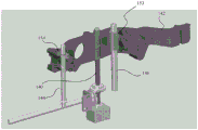
FIG. 1 depicts a perspective top view of a table saw mounted to a belt wheel carriage;
FIG. 2 depicts a side plan view of the right side of the table saw of FIG. 1 and with the housing, bevel plate and workpiece support surface removed and the height adjust carriage in an upper position;
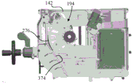
FIG. 3 depicts a side plan view of the left side of the table saw of FIG. 1 with the housing, the workpiece support surface, and the bevel plate removed;
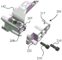
FIG. 4 depicts a perspective top view of the height adjustment carriage, drop arm assembly and motor assembly of the table saw of FIG. 1;
FIG. 5 depicts a perspective top view of the height adjust carriage of FIG. 4 along with a rod and tube to guide the movement of the height adjust carriage;
FIG. 6 depicts a side cross-sectional view of the motor assembly of FIG. 4;
FIG. 7 depicts a plan view of the motor assembly of FIG. 4 from the left side of the table saw;
FIG. 8 depicts a plan view of the motor assembly of FIG. 4 after the motor assembly has been rotated to provide the desired tension to the belt of FIG. 4, as viewed from the left side of the table saw;
FIG. 9 depicts a side plan view of the track portion of the height adjust carriage of FIG. 4;
FIG. 10 depicts an exploded view of the track portion of FIG. 9;
FIG. 11 depicts a partially exploded view of an exemplary embodiment of a track section;
FIG. 12 depicts a perspective top view of another exemplary embodiment of a rail bracket;
FIG. 12A depicts a top plan view of the rail bracket of FIG. 12;
FIG. 13 depicts a cross-sectional view of the track assembly of FIG. 10 supporting a drop arm assembly;
FIG. 14 depicts a bottom perspective cross-sectional view of the track assembly of FIG. 13;
FIG. 15A depicts an exploded view of the drop arm assembly of FIG. 4;
FIG. 15B depicts a side perspective view of the drop arm assembly of FIG. 4;
FIG. 15C depicts a side plan view of the drop arm assembly of FIG. 4;
FIG. 16 depicts a side plan view of the right side of the table saw of FIG. 1 with the housing and the workpiece support surface removed;
FIG. 17 depicts a perspective view of the height adjustment carriage of FIG. 4, and with a pyrotechnic assembly (pyrotechnical) and latch assembly mounted to the height adjustment carriage;
FIG. 18 depicts a perspective view of the cartridge of FIG. 17;
FIGS. 19 and 20 depict perspective views of the pyrotechnic housing of FIG. 17;
FIG. 21 depicts a partial top plan view of the table saw of FIG. 1 and with the throat plate removed;
FIG. 22 depicts a side cross-sectional view of the drop arm frame of FIG. 4 showing a common point shared by the location and center of gravity of the ribs of the drop arm frame;
FIG. 23 depicts a side perspective view of the pyrotechnic housing mounted to the height adjust carriage;
FIG. 24 depicts an exploded view of the pyrotechnic assembly of FIG. 17;
FIG. 25 depicts a top plan view of the active shot (active shot) of FIG. 17 with electrical connections;
26-29 depict the action projectile of FIG. 17 moving the latch assembly of FIG. 17 when the reaction plug of FIG. 24 is threaded into the pyrotechnic housing;
30-31 depict the latch assembly of FIG. 17 biasing the active projectile outward from the pyrotechnic housing when the reaction plug is removed;
FIG. 32 depicts a side plan view of the drop arm assembly of FIG. 4 indicating the axes of the various components;
FIG. 33 depicts a side plan view of the table saw of FIG. 1 after the drop arm assembly has been dropped against the surface with the height adjust carriage at the upper position;
FIG. 34 depicts a side plan view of the table saw of FIG. 1 and with the drop arm assembly locked and the height adjust carriage in a lower position;
FIG. 35 depicts a side plan view of the table saw of FIG. 1 after the drop arm assembly has been dropped against the surface and the height adjust carriage is at the lower position;
figure 36 depicts a perspective top view of the bounce latch assembly mounted to the height adjustment carriage;
37-39 depict left, top and right plan views of the height adjust carriage showing a rib configuration to provide increased strength;
40-41 depict perspective views of a ramp carriage showing a rib configuration to provide increased strength;
FIG. 42 depicts a saw control unit assembly mounted to a bevel carriage;
FIG. 43 depicts an exploded view of the saw control unit assembly and bevel carriage of FIG. 42;
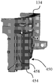
FIG. 44 depicts an exploded view of the saw control unit assembly, drop arm assembly and bevel carriage of FIG. 42;
FIG. 45 depicts a side perspective view of the ramp carriage showing coaxial wiring to provide communication with various components;
FIG. 46 depicts a shield and center conductor of coaxial wiring to provide electrical communication with various components;
FIG. 47 depicts a perspective view of the connection between the center conductor and the CCP;
FIG. 48 depicts a perspective view of the coaxial wiring offset from its normal position where it is connected to the ramp carriage and with the protective cover removed to show the exposed shield connected to the ramp carriage;
49-50 depict a protective cover to cover the stripped portion of the coaxial wire and also provide communication between the coaxial wire and other components;
FIG. 51 depicts a side perspective view of the table saw of FIG. 1, and with the housing removed to show how the components communicate with the coaxially routed shield;
FIG. 52 depicts an exploded view of the trunnion to pivot the ramp carriage, showing electrical isolation between the workpiece support surface and the ramp carriage;
FIG. 53 is a cross-sectional view of the arbor shaft showing the arbor shaft electrically isolated from the remainder of the belt and drop arm assembly;
FIG. 54 is an exploded view of the pulley of FIG. 53, providing electrical isolation between the belt and the arbor;
FIG. 54A is a side plan view of the outer shell of FIG. 54 showing the dovetail splines;
FIG. 55 depicts a perspective view of the motor assembly showing radially directed vents directing carbon dust away from one or more components;
FIG. 56 depicts a partially exploded view of the workpiece support surface and throat plate of FIG. 1;
FIG. 57 depicts a perspective view of the throat plate engaged by the knob with the workpiece support surface removed;
FIG. 58 depicts a top perspective view of the knob of FIG. 56;
FIG. 59 depicts a side plan view of the front of the throat plate;
FIG. 60 depicts a partial perspective view of the drop arm assembly, and wherein the arbor lock of FIG. 15B engages the pyrotechnic housing to maintain the drop arm assembly in a locked condition;
FIG. 61 depicts a partial top perspective view of the table saw of FIG. 1 and with the throat plate removed to allow resetting of the drop arm assembly;
FIG. 62 depicts a side perspective view of the HMI unit of FIG. 1;
FIG. 63 depicts an exploded view of the internal components of the HMI unit of FIG. 62;
FIG. 64 depicts a rear plan view of the table saw of FIG. 1 and with the bevel carriage at zero degrees;
FIG. 65 depicts a rear plan view of the table saw of FIG. 1 and with the bevel carriage at a forty-five degree incline such that the USB port of the saw control unit assembly is visible through the dust port access slot of the table saw housing; and
fig. 66-67 depict protective covers that can be used to protect the USB port of fig. 65 from unwanted access.
Corresponding reference characters indicate corresponding parts throughout the several views. Like reference numerals designate like parts throughout the several views.
Detailed Description
While the power tool described herein is susceptible to various modifications and alternative forms, specific embodiments thereof have been shown by way of example in the drawings and will herein be described in detail. It should be understood, however, that there is no intention to limit the power tool to the specific forms disclosed. Rather, the intention is to cover all modifications, equivalents, and alternatives falling within the spirit and scope of the disclosure as defined by the appended claims.
Referring to FIG. 1, a table saw assembly 100 is shown. The table saw assembly 100 includes a table saw 102 mounted to a wheel carriage 104. The table saw 102 includes a base housing 106 and a workpiece support surface 108. Support surface extensions 110 and 112 are provided to assist in supporting larger workpieces. A guide plate 114 is provided to guide the workpiece along the workpiece support surface 108.
A riving knife or dispenser 116 is positioned adjacent the forming device, which in this embodiment is a blade 118 that extends from within the base housing 106 to above the workpiece support surface 108. A blade guard 120 and kick-back pawl (kick-back paw) 117 may be attached to the dispenser 116. The blade 118 extends through a slot in a throat plate 122. A Human Machine Interface (HMI) unit 124 is provided at the front of the table saw 102.
An angle indicator 130 positioned adjacent the HMI unit 124 indicates the angle of the blade 118 relative to the workpiece support surface 108. The bevel adjustment lock 132 may be used to establish the angle of the blade 118 relative to the workpiece support surface 108 by pivoting a bevel carriage 134 (shown in fig. 2) within the base housing 106. The ramp carriage 134 is then clamped between the ramp adjustment lock 132 and the ramp clamp 133 (see fig. 3). As further depicted in fig. 3, a height adjustment wheel 136 is used to adjust the height of the blade 118 above the workpiece support surface 108 (not shown in fig. 3). Rotation of the height adjustment wheel 136 rotates a bevel gear 138 that engages a threaded rod 140. The threaded rod 140 is thus forced to rotate either clockwise or counterclockwise (depending on the direction in which the height adjustment wheel 136 is rotated).
The threaded rod 140 threadedly engages the height adjustment carriage 142. In one embodiment, the threaded rod 140 engages a threaded bushing 152 of the height adjustment carriage 142. The height adjust carriage 142 is thus forced to move up and down as the threaded rod 140 rotates. Rotation of the height adjust carriage 142 is prevented by a height adjust rod 144 and a height adjust tube 146 fixedly attached to the ramp carriage 134. The height adjustment rod 144 and the height adjustment tube 146 extend through openings 148 and 150, respectively, in the height adjustment carriage 142, which are shown in FIG. 4.
To reduce the weight of the table saw 102, a lightweight material, such as aluminum, is used in the manufacture of the height adjustment carriage 142. While effective for reducing weight, aluminum is generally not strong enough to withstand the various forces applied to the height adjust carriage 142 without deformation or damage (described more fully below). Accordingly, a powder metallurgy bushing 153, shown more clearly in FIG. 5, is provided within the opening 150. The bushing 153 distributes forces evenly along the opening 150, thereby reducing the likelihood of damage, particularly at the mouth of the opening 150, which can result in undesirable "slack" between the height adjust carriage 142 and the height adjust tube 146.
Similarly, a powder metallurgy slotted bushing 154 is provided at the upper mouth of opening 148 to protect opening 148 from damage from height adjustment rod 144. In other embodiments, one or more of the bushings 153/154 are replaced with linear bearings or split guide pads. In some embodiments, the ramp carriage 134 is protected by incorporating a dampening bushing at the location that supports the height adjustment rod 144 and/or the height adjustment tube 146.
Returning to fig. 4, the motor assembly 160 is supported by the height adjust carriage 142. The motor assembly 160 drives the belt 162 via an offset drive shaft 164 and pulley 166, shown more clearly in fig. 6, the belt 162 being made of a conductive material in one embodiment. Offset drive shaft 164 is offset from power shaft 168 by gear 170. The motor assembly 160 is attached to the height adjust carriage 142 in a manner that allows the belt 162 to be tensioned without the need for a linear tensioner, as explained with reference to fig. 7.
As shown in fig. 7, the motor assembly 160 is attached to the height adjustment carriage 142 with four screws 172, the four screws 172 being inserted through corresponding mounting slots 174 in a motor gear housing 176. Mounting slot 174 is oriented to define a motor mounting axis of rotation 178 that is below an axis of rotation 180 of power shaft 168, with power shaft 168 correspondingly lower than offset shaft 164. Accordingly, rotation in one direction of the jack screw 182 that is in threaded engagement with the plate 184 fixedly attached to the height adjust carriage 142 causes the jack screw (jack screw) 182 to push the plate 186 attached to the motor gear housing 176. In one embodiment, the plate 184 is either formed as part of the height adjust carriage 142 or integrated into the height adjust carriage 142 as a single unit. Thus, instead, the jack screw 182 is threadedly engaged with the height adjust carriage 142. Because the plate 186 impacted by the ejection screw 182 is above the motor mount axis of rotation 178, the motor assembly 160 rotates in the direction of arrow 188 from the position of fig. 7 to the position of fig. 8.
Returning to fig. 4, the above-described movement of the motor assembly 160 causes the pulley 166 attached to the offset drive shaft 164 to move in the direction of arrow 190 away from a driven pulley 192 rotatably supported by a drop arm assembly 194. Thus, the belt 162 is placed in tension. Accordingly, for initial assembly, the motor assembly 160 can be placed in the position of fig. 7 and then pivoted toward the position depicted in fig. 8 to a position that provides the desired tension of the belt 162. This configuration requires less linear travel than a linear adjustment mechanism to achieve the same tension within the constrained space. In other embodiments, a spring-loaded actuator replaces the ejection screw 182 to maintain the strap tension over time.
The tension of the strap 162 is verified using a strap tension meter inserted through a strap tension access port 196 (see fig. 4) in the upper surface of the strap protection cover 198. The positioning of the access port 196 on the upper surface of the belt guard 198 allows access to the belt 162 from above the table saw 102. This allows for easier setting of the tension of the belt while maintaining the structural requirements of the height adjustment carriage without having the saw flip up and down to gain access to the belt 162. Although depicted as a circular opening, in other embodiments, the access port 196 is of a different geometry, and in some embodiments is provided with a removable plug or access door.
Continuing with fig. 4, the drop arm assembly 194 is movably connected to the height adjust carriage 142 by a track shaft 200 defining a drop arm track axis 201. The position of the drop arm track axis 201 is controlled to be positioned between the axis of rotation 202 of the offset drive shaft 164 (see fig. 6), which is also the axis of rotation of the pulley 166, and the axis of rotation 183 of the driven pulley 192 using the track carriage 203 as further described with reference to fig. 9-10.
The rail bracket 203 includes a rail shaft hole 204 through which the rail shaft 200 is inserted. The track bracket 203 also includes an alignment aperture 205 and an anti-rotation slot 206 that receive a locator pin 207 and an anti-rotation pin 208, respectively, extending from the height adjust carriage 142. The rail bracket 203 is connected to the height adjust carriage 142 by two screws 210.
The axis 211 of the anti-rotation slot 206 is aligned to intersect the central axis 212 of the alignment bore 205. Accordingly, when locator pin 207 and anti-rotation pin 208 are positioned within alignment aperture 205 and anti-rotation slot 206, respectively, anti-rotation pin 208 and anti-rotation slot 206 provide precise angular positions for alignment of drop arm track axis 201.
The incorporation of the rail bracket 203 with the anti-rotation slot 206 and the anti-rotation pin 226 enables the use of lightweight materials while providing increased accuracy in positioning the saw blade 118. In some embodiments, precise positioning of the track carriage is achieved using two shoulder screws 213 (see fig. 11), or alignment pins 214 (fig. 12), received in corresponding apertures (not shown) on the height adjust carriage 142. Alignment of the saw blade 118 is also provided by incorporating an inner face 228 of the rail bracket 203 at an angle 230 of about 0.65 ° relative to a plane parallel to the drop plane (see below and fig. 21). This angling of the interior faces provides increased accuracy in positioning the blade 118 through various bevel angles even when the strap 162 is under increased tension.
Increased accuracy in positioning the blade 118 is also provided by the manner in which the drop arm assembly 194 is movably coupled to the height adjust carriage 142. Specifically, as shown in fig. 13, the rail axle 200 is movably supported by two bearings 215 within a drop arm frame 242 of the drop arm assembly 194. The track bolt 232 threadingly engages the track shaft 200 and compresses the bearing 215 against the inner bearing wall 234 of the spaced apart brackets 236 of the drop arm frame 242.
The shoulder 222 is formed in the track shaft bore 204 by forming a lower circular portion 224 of the track shaft bore 204 and an upper circular portion 226 of the track shaft bore 204. The diameter of the lower circular portion 224 is substantially the same as the diameter of the orbit shaft 200. In various embodiments, the upper circular portion 226 has the same or different diameter as the lower circular portion 224. However, the origin of the upper circular portion 226 is offset from the origin of the lower circular portion 224 in a direction opposite the position of the set screw 220.
Accordingly, the upper rounded portion 226 provides sufficient clearance for a snug fit between the track shaft 200 and the track shaft aperture 204. At the same time, the junction of the upper rounded portion 226 and the lower rounded portion 224 forms a shoulder 222 that extends along the entire length of the rail axle bore 204. Thus, when set screw 220 is installed, set screw 220 forces rail shaft 200 against shoulder 222, thereby forming a "three-point" lock between each set screw and the shoulder.
In some embodiments, the shoulder is replaced by two ball bearings that are pressed into the drop arm frame 242 using the outer race of the bearing. The rail shaft 200 is then inserted and with one side of the rail shaft engaging the inner race of one of the bearings. The track bolt is then screwed into the track shaft inboard from the opposite direction of the track shaft, thereby engaging the inner race of the other bearing. The orbital shaft and bolt assembly move the inner races of the two bearings toward each other. With the outer race secured in the drop arm and the inner race pulled together, the internal clearance is minimized, thus reducing or eliminating motion between the sides due to the internal clearance of the bearing.
Turning now to fig. 15A-15C, the drop arm assembly 194 is depicted in greater detail. As noted above, the driven pulley 192 is engaged with the belt 162 and is rotatably supported by the drop arm assembly 194. More specifically, the driven pulley 192 is rotatably supported by an arbor (arbor) 240, the arbor 240 being configured to rotatably support the blade 118 (see fig. 1). The arbor shaft 240 is rotatably supported within a drop arm frame 242.
The drop arm frame 242 also includes a spring recess 244 (fig. 15B) that houses a spring 246. The spring 246 is operatively connected to a flange 248 of a arbor lock 250. The arbor lock 250 includes an activation arm 252 and a locking ramp 254 positioned above the drop arm frame 242. The arbor 240 extends through the arbor slot 256 and two shoulder screws 258 extend through the guide slots 260 and threadingly engage the drop arm frame 242.
The drop arm assembly 194 includes a Capacitive Coupling Plate (CCP) 262 from which tab 264 extends. The CCP is mounted to the CCP bracket 268 using screws, five screws are illustrated, which are either the same or different types of screws 266, and the CCP bracket 268 is correspondingly mounted to the drop arm frame 242 using three set screws 269. CCP bracket 268 includes a raised lip 270 configured to provide electrical isolation between the CCP and the blade. While a single piece CCP bracket 268 is depicted in the embodiment of fig. 15a, in other embodiments, the bracket is formed using a plurality of modules that are not connected to each other in some embodiments.
CCP262 is part of a capacitive sensing system (discussed in more detail below) and is made of an electrically conductive material. As best depicted in fig. 15C, the shape of CCP262 is asymmetric. Also, the center of mass of the CCP262 moves toward the rail member (orbit) 272 of the drop arm frame 242. This shape provides sufficient capacitance while reducing the inertia of the drop arm assembly 194. In one embodiment, the finishing treatment for the CCP262 is a non-conductive coating. Acceptable coatings include manganese phosphate for steel CCPs and anodization for aluminum CCPs. Such thin, non-conductive covers provide isolation against accidental contact between the blade and the conductive portion of the CCP due to blade deflection during heavy cutting.
Specifically, screws 266 are used to mount the CCP262 to the CCP bracket 268 via threaded engagement protrusions 271. Optionally, a fastening element such as a nut (not shown) can be used in addition to the screw 266 to mount the CCP262 to the CCP bracket 268. In another embodiment, CCP bracket 268 is injection molded to CCP262 as a single unit. Thus, no fastening elements are required. The protrusions 271 are then inserted into the recesses 273 formed in the drop arm frame and adjusted to position the CCP262 at the desired location. The set screw 269 is then inserted through the aperture in the recess 273 to engage the projection 271.
The protrusions 271 electrically isolate the screws 266 and the CCP262 from the drop arm frame 242. The raised lip 270 of the CCP bracket 268 wraps around the CCP262 along the outside edge to protect the CCP262 from incidental contact with the blade during a power cut.
Continuing with fig. 15C, track member 272 includes a resilient tab 274/275 (see also fig. 15A) and a pad 276 mounted to the lower surface of drop arm frame 242. As best seen in fig. 15B, the drop arm assembly 194 further includes a latch pin 282, a hemispherical strike pin 280 and two alignment pins 278 supported by the drop arm frame 242.
Referring now to fig. 16, the drop arm assembly 194 is maintained in the latched position by the latch 300. The latch 300 is movably connected to a pyrotechnic housing 322 by a pin 302. The latch 300, also shown in fig. 17, includes a latch pin receiving area 304 that engages the latch pin 282 in the lockdown position. The latch 300 also includes two tines (prong) 306. The latch 300 is biased by a spring 308 such that the tines 306 are biased into contact with an actuator, which in one embodiment is a shot (shot) 310.
The projectile 310 is paired with another actuator or projectile 312 through a barrel 314 shown in fig. 18. The bridge 320 couples the two actuators or projectiles 310/312 in the barrel 314.
The cartridge 314 is shown mounted in a pyrotechnic housing 322 (also referred to as an actuator housing) in fig. 17. The pyrotechnic or actuator housing 322, also shown in fig. 19-20, includes an internally threaded chamber 324, a mounting plate 326 and a finger plate 328. The locking ramp 364 is located at an upper portion of the finger plate 328. The slit 330 extends along one side of the internally threaded chamber 324 and terminates at a rounded end portion 332. This arrangement allows for optimal positioning of the reaction projectile as explained further with reference to fig. 21 and 22.
FIG. 21 depicts a partial top plan view of the table saw 102 and wherein the throat plate 122 is removed from the throat plate opening 334. Visible through the throat opening 334 are an arbor nut 336 and blade 118 mounted to the arbor shaft 240. A portion of the drop arm 194 and the height adjust carriage 142 are also visible through the throat opening 334. Also depicted in fig. 21 is a drop plane 338. The drop plane 338 is a plane that is aligned with the interconnection of the projectile 310 and the drop arm assembly, and the drop arm assembly moves in a generally parallel manner along the drop plane 338 when the saw control system is activated, as discussed more fully below. Fig. 22 depicts a cross-sectional view of the drop arm assembly 194 taken parallel to the drop plane 338 of fig. 21.
Fig. 21 and 22 thus illustrate that the drop arm assembly 194 is configured such that the center of gravity 340 of the drop arm assembly 194 is located on, proximate to, or adjacent to the drop plane 338 such that the transfer of force from the projectile to the hemispherical strike pin 280 occurs as close as practicable to the drop plane 338.
Accordingly, pyrotechnic housing 322 is configured to substantially center the active projectile on drop plane 338. This results in reduced stress of the system and reduced sag time of the drop arm assembly 194. Additionally, the inactive projectiles (projectiles 312 in the configuration of fig. 21) are positioned inwardly with respect to the active projectiles while maintaining the barrel 314 in a position that is easily accessible through the throat plate opening 334. This arrangement ensures that the non-active projectile does not interfere with the movement of the drop arm assembly 194.
To further improve the alignment of the action projectile with the hemispherical strike pin 280, an alignment housing 342 is mounted to the pyrotechnic housing 322, as shown in fig. 17. The alignment housing 342 receives the hardened steel alignment pin 278 (fig. 15B), thereby reducing blade deflection under load and ensuring proper alignment between the active projectile and the hemispherical strike pin 280. The provision of the pin 278 in the drop arm assembly 194 also provides enhanced stabilization of the drop arm frame 242 against torsional loading or side loading relative to the rail axle 200 (fig. 4). The use of hardened steel pins as alignment pins extending from the aluminum drop arm frame 242 achieves this benefit while allowing for a lightweight/low inertia drop arm frame 242.
Although two pins 278 are shown in fig. 15B, in other embodiments, only one is used. In yet another embodiment, one or more protrusions or surfaces are used in the system. Additionally, in some embodiments, the alignment housing is positioned in the drop arm assembly 194 with the hardened steel pin extending from the pyrotechnic housing 322. In further embodiments, the alignment features are integrated into the latch 300 and/or the projectile.
A slot 330 in the housing 322 receives the bridge 320 of the barrel 314. The slot 330 thus allows for the incorporation of a spare projectile into the barrel 314. However, the slit 330 weakens the pyrotechnic housing 322. Thus, support is required at both a forward position and a rearward position relative to the slot 330 to prevent failure of the pyrotechnic housing 322. While the rear mounting plate 326 is securely bolted to the height adjust carriage 142 with two bolts 346 and pins 348 shown in fig. 23, the bolting of the front portion of the pyrotechnic housing 322 will result in unacceptably high stresses, even if a rounded tip portion 332 is provided that inhibits cracking at the tip of the slit 330. For this reason, finger plates 328 are used.
As depicted in fig. 17, the front portion of the pyrotechnic housing 322 is supported by contact between the finger plate 328 and the finger rib arrangement 344 on the height adjustment carriage 142. The finger plates 328 thus transmit force in the direction of the pyrotechnical effect (pyrotechnic) (below the pyrotechnic housing 322), but do not constrain the pyrotechnic housing 322 in any other degree of freedom, which greatly reduces the stress level in that portion and allows the pyrotechnic housing 322 to be formed from a affordable and lightweight material. In this embodiment, three fingers are provided. In other embodiments, more or fewer fingers are provided.
The disclosed pyrotechnic system provides a number of additional features. For example, the pyrotechnic assembly 350 of fig. 24 includes two projectiles 310/312. While in some embodiments the saw control system provides an electrical check to ensure that an unused projectile is connected, in some embodiments the safety control system is not configured to ensure that the connected projectile is properly installed in the pyrotechnic housing 322 and thus aligned with the hemispherical strike pin 280. However, the pyrotechnic assembly 350 shown in fig. 24 is configured to ensure that the user does not mistakenly connect the wrong projectile.
Fig. 24 depicts a pyrotechnic assembly 350 that includes a pyrotechnic housing 322, a cartridge 314, and a projectile 310/312, which have been described above. Pyrotechnic assembly 350 also includes electrical connector 352, connecting wire 354, and reaction plug 356.
Typically, the projectile 310/312 and barrel 314 are provided as a single unit. In addition, the table saw 102 is provided with a connection wire 354 that is inserted through an opening 358 of the reaction plug 356, as best shown in FIG. 25. One end of the connection line 354 is permanently attached to the saw control unit while the other end is attached to the electrical connector 352.
In other embodiments, the reactive plug 356 and the electrical connector 352 can be replaced with snap caps or flashlight-type caps. Additionally, in such an embodiment, electrical connector 352 can be omitted and replaced with a simple pigtail (pigtail) connector.
The reaction plug 356 also assists in the latching-out function, which ensures that the cartridge 314 is properly seated within the pyrotechnic housing 322. As shown in fig. 26, the spring 308 biases the latch 300 in a clockwise direction. When the reaction plug 356 is not properly threaded into the internally threaded chamber 324 as depicted in fig. 26, the tines 306 force the shot 312 upwardly within the internally threaded chamber 324 and the latch 300 is rotated in a clockwise direction to a position where the lower surface of the lower portion 360 of the latch 300 is positioned within the drop path of the latch pin 282. Accordingly, the counterclockwise orbital motion of the drop arm assembly 194 is constrained by contact between any portion of the drop arm assembly and the lower portion 360. Thus, the latch pin 282 cannot be received within the latch pin receiving area 304.
By rotating the reaction plug 356 in a direction such that it further engages the internally threaded chamber 324, the reaction plug 356 is forced against the barrel 314 or projectile 310, thereby forcing the projectile 310 or barrel 314 against the tines 306. This forces the spring 308 to compress and rotate the latch in a counterclockwise direction, resulting in the configuration of fig. 27. In fig. 27, the counterclockwise orbital motion of the drop arm assembly 194 is still constrained by contact between the latch pin 282 and the lower surface of the lower portion 360.
Continued rotation of the reaction plug 356 fully seats the barrel 314 within the internally threaded chamber 324, further rotating the latch 300 to the configuration of fig. 28. In fig. 28, the latch 300 has been rotated so that the side surface of the lower portion 360 is within the drop path of the latch pin 282. Accordingly, by orbiting the drop arm assembly 194 in a counterclockwise direction, as the latch pin 282 slides up the side surface of the lower portion 360, the latch pin 282 presses against the side surface of the lower portion 360, further compressing the spring 308 and rotating the latch 300 in a counterclockwise direction.
Continued counterclockwise orbital movement of the drop arm assembly 194 moves the latch pin 282 over the side surface of the lower section 360. Accordingly, the spring 308 forces the latch 300 to rotate in a clockwise direction, resulting in the configuration of fig. 29. In fig. 29, the latch 300 has been rotated in a clockwise direction such that the latch pin 282 is received within the latch pin receiving area 304.
Accordingly, if the reaction plug 356 is not sufficiently threaded into the pyrotechnic housing 322, the latch 300 provides a mechanical "lockout" and the drop arm assembly 194 is not able to be lifted into the cut/lock position. Although described with respect to a pyrotechnic device, the reaction plug 356 can be used with any desired type of actuator that provides both mechanical and electrical latching capabilities.
The reaction plug 356 is generally configured so that it can be easily turned by hand. In one embodiment, the reaction plug 356 includes ribs 362 (see fig. 24) configured to allow tightening/loosening. The ribs 362 are further configured to allow the reaction plug 356 to be tightened/loosened with a wrench (not shown). In some embodiments, the reaction plug is a hexagonal plug that can be turned with a standard hexagonal wrench rather than a wrench. In further embodiments, a locking feature separate from the reaction plug is provided that requires a tool to allow rotation of the reaction plug. For example, the locking feature may be a spring loaded component (ball bearing, spring tab) that operates by pushing on a locking tab that requires a screwdriver or similar tool to release. In other embodiments, holes and extrusion pins with round reaction plugs are used, which require special wrenches to tighten and loosen the reaction plugs.
Biasing the latch 300 into the active shot by the spring 308 also assists in the removal of the barrel 314 as explained initially with reference to fig. 30. Fig. 30 depicts the cartridge 314 fully seated within the pyrotechnic housing 322. To remove the barrel 314, the reaction plug 356 is removed. Removal of the reaction plug 356 allows the barrel 314 to be pushed up to the position depicted in fig. 31 as the latch 300 is biased against the action projectile. The user can then grasp the upper portion of the cartridge 314 over the inactive projectile rather than pulling the cartridge 314 using the connection line 354.
Referring back to fig. 16, when the active projectile 310 is activated by the saw control system, the projectile 310 applies a force to the drop arm assembly 194 through the hemispherical strike pin 280, wherein the hemispherical strike pin 280 is generally aligned with the drop plane 338 through the housing 322. This force is transferred to the latch pin 282 (see fig. 29), which forces the latch 300 to compress the spring 308 and move the latch pin receiving portion 304 of the latch 300 out of the drop path of the latch pin 282. The drop arm assembly 194 then orbits in a clockwise direction, moving the blade 118 (see fig. 2), the blade 118 being mounted to the arbor shaft 240 below the workpiece support surface 104.
As described above, the position of the drop arm track axis 201 is controlled to lie between the axis of rotation 202 of the offset drive shaft 164 and the axis of rotation of the driven pulley 192. This arrangement provides increased drop velocity of the drop arm assembly 194 and prevents damage or stretching of the belt which would result in degradation of powertrain performance, as explained further with reference to fig. 6, 15A and 32. Fig. 32 shows the drop arm orbit axis 201, the axis of rotation 202 of the offset drive shaft 164, and the axis of rotation 183 of the driven pulley 192. Because the pulley 166 is mounted to the height adjust carriage 142 and the driven pulley 192 is mounted on the drop arm assembly 194, the tensioning of the belt 162 moves the pulley 166 away from the drop arm track axis 201 (to the left in fig. 32) as described above. Thus, during the drop arm drop, the driven pulley 192 moves toward the pulley 166. Accordingly, axis 183 moves closer to axis 202. This reduction in distance allows the belt to relax, which results in a faster sag time.
The impact of the drop arm assembly 194 is partially absorbed by contact between the pad 276 and the surface 374, as shown in fig. 33. The pad 276 is mounted on the drop arm assembly 194 using any desired mounting means, such as glue, fasteners, clamping plates, etc. Positioning the pad 276 on the drop arm assembly 194 allows for a pad with a smaller sized geometry than mounting the pad on the surface 374.
For example, fig. 33 depicts the location of the impact between the drop arm assembly 194 and the surface 374 when the height adjust carriage 142 is initially in the fully raised position as depicted in fig. 2. When the height adjust carriage 142 is at the lowermost position depicted in fig. 34, the drop arm assembly 194 contacts the surface 374 at a lower position as depicted in fig. 35. Thus, covering the span of the surface 374 contacted by the drop arm assembly 194 would take more material than would be required to cover the portion of the drop arm assembly 194 contacting the surface 374. Thus, mounting the pad 276 on the drop arm assembly 194 reduces the amount of pad material required.
The configuration of the drop arm frame 242 is thus selected in part to provide a desired surface for the contact surface 374. Returning to fig. 22, the configuration of the drop arm frame 242 is further selected to reduce the weight of the drop arm frame 242. As depicted in fig. 22, a number of ribs 376/378/380/382 extend from the lower surface 384 to openings 386 that receive the arbor shaft 240. The ribs 376/378/380/382 provide strength that allows for the use of less material and/or allows for the use of lighter materials. In the context of the drop arm assembly 194, this translates into a reduced moment of inertia, thereby providing a more rapid descent of the drop arm assembly in response to a sensed unsafe condition.
The ribs 376/378/380/382 also reduce the resiliency of the drop arm assembly 194 once the pad 276 contacts the surface 374. As shown in fig. 22, each of the ribs 376/378/380/382 defines a respective axis 388/390/392/394. Axes 388/390/392/394 intersect at a point 396, and point 396 is coincident with center of gravity 340, adjacent center of gravity 340, and immediately adjacent center of gravity 340. This configuration reduces the rebound energy and allows a further reduction in the amount or weight of material.
The above-described configuration is generally insufficient to dissipate all of the bounce energy of the drop arm assembly 104. Accordingly, as shown in fig. 36, a rebound latch assembly 400 is provided. The bounce back latch assembly 400 includes a lower latch 402 and an upper latch 404 that are independently movably connected to the track bracket 203 by a pin 406. In some embodiments, the pin 406 is sized longer than necessary to provide tolerance. A wave washer (not shown) may be used between the head of the pin 406 and the latch 404 to allow for tolerances while providing the desired tension to the system.
The lower latch 402 and the upper latch 404 are biased into contact with a resilient surface 408 of the drop arm frame 242 by two springs 410 and 412, respectively. Spring 410/412 is anchored to rail bracket 203 by bolt 414. The rebound latch assembly 400 also includes a reset lever 416 that extends from the lower latch 402 to a position above the track bracket 203.
During the orbital movement of the drop arm assembly 194 in response to the sensed unsafe condition, the rebound surface 408 orbits in a clockwise direction (as viewed in fig. 36). As the resilient surface 408 orbits, the resilient tab 275 (see fig. 15A) orbits over the lower latch 402. Accordingly, the spring 410 biases the lower latch 402 into contact with the resilient surface 408 at a location inward of the outermost extent of the resilient projection 275. Subsequently, the drop arm assembly 194 contacts the surface 374 as described above. As the drop arm assembly 194 rebounds away from the surface 374, the lower latch 402 contacts the rebound ledge 275, thereby preventing further upward (counterclockwise) movement of the drop arm assembly 194.
Resilient tab 274 (see fig. 15A) and upper latch 404 operate similarly. The primary difference is that in order for the resilient projection 274 to track under the upper latch 404, a greater clockwise orbital movement of the resilient surface 408 is required. This occurs, for example, when the height adjust carriage 142 is positioned toward its uppermost position (such as the height depicted in fig. 16). Accordingly, at a higher position, resilient protection is provided by resilient tab 274 and upper latch 404, while at a lower height, such as the height depicted in fig. 34, resilient protection is provided by resilient tab 275 and lower latch 402.
When the user wishes to return the drop arm assembly 194 to the lock position, the user pushes the reset lever 416, which moves the lower latch 402 away from the resilient surface 408. Additionally, the lip 418 of the lower latch 402 contacts the upper latch 404, moving the upper latch 404 away from the resilient surface 408. The drop arm assembly 194 can then be raised to the latched position retained by the latch 300.
The above-described use of the rib configuration to reduce the weight of the drop arm assembly 194 also reduces the overall weight of the table saw 102, thereby making the table saw 102 more portable. The rib configuration is used in other areas of the table saw for the same purpose. For example, fig. 37-39 depict various views of the height adjustment carriage 142. A large number of rib arrangements 420 are provided to accommodate the large impact forces from the projectiles 310/312.
Similarly, as depicted in fig. 40-41, the ramp carriage 134 includes a rib configuration 422/424/426/428, among other structural features. Openings 430 and 432 are also shown in fig. 40-41. The rib arrangements 424 and 428 provide structural support for the surface 374, which surface 374 is impacted by the drop arm assembly 194 as described above. The rib configurations 422 and 426 and other structural features provide support that allows the openings 430 and 432 to be accommodated. The opening 430 is required to allow for installation of the motor assembly 160 (fig. 4), while the opening 432 is provided to enhance operation of the saw control unit, as will be discussed in greater detail below. In addition, removing material to form the opening 432 reduces the weight of the saw.
Accordingly, in one embodiment, a rib configuration is used throughout the table saw 102 to keep the table saw 102 light and portable without compromising the structure. Nonetheless, selective areas and components of the table saw 102 are provided in the form of a more robust material to ensure optimal function of the table saw 102, even after multiple pyrotechnic activations. For example, the force of a crash of a drop is transmitted through the drop arm, the rail bracket and into the height adjustment bar. Accordingly, the area of the track bracket 216 (FIG. 10) and the ramp/height adjust carriage surrounding the height adjust rod is typically formed of stronger and or heavier materials. Likewise, in some embodiments, the alignment housing 342 (fig. 17), pyrotechnic housing, and latch 300 are formed from stronger materials, such as by using powder metallurgy, zinc die casting, or the like.
Since many of the structural components are formed of lightweight materials, forces from pyrotechnic operations and from the arrestment (restraining) pendant arm assembly 194 are not dampened. The transmitted forces must therefore be taken into account when positioning sensitive components. One such sensitive component is housed within the saw control unit assembly 450 of fig. 42, which is mounted to the bevel carriage 134. The saw control unit assembly 450 includes electronics for controlling the table saw assembly 100. Such electronics include a memory with program instructions stored therein that, when executed by the processor of the saw control unit assembly 450, control the safety control system.
As shown in fig. 43, the saw control unit assembly 450 includes a Printed Circuit Board (PCB) 452 mounted to an outer housing 454. The outer housing 454 is correspondingly mounted to the inner housing 456. The saw control unit assembly 450 is then mounted to the bevel carriage 134. The inner housing 456 and the outer housing 454 electrically isolate the PCB 452 from the ramp carriage 134. The USB port 458 (see fig. 42) provides electronic access to the PCB 452.
The foregoing configuration of the saw control unit assembly 450 provides dampening of forces from pyrotechnic operation and from the resistance drop arm assembly 194. Nevertheless, some force may still be transferred to the PCB 452. Accordingly, if the PCB 452 is mounted perpendicular to either of these force vectors, a large shock/vibration load will be applied to the PCB 452, which can cause damage to the PCB 452. Accordingly, as best seen in fig. 44, PCB 452 is mounted at an angle of approximately 15 degrees relative to the plane in which the impact and projectile forces on surface 374 are applied.
If the PCB 452 is mounted in close proximity and parallel to a conductive body (such as a ramp carriage, as discussed in more detail below) that carries the signal, the signal can be capacitively coupled to the PCB 452 and cause undesirable noise in other signals. Thus, the bevel carriage 134 and saw control unit assembly 450 are configured such that there are no parallel metal surfaces to couple noise to the PCB 452. For this reason, an opening 432 is provided in the ramp carriage 134.
While mounting of the PCB 452 on the ramp carriage 134 is convenient for routing purposes, as discussed further below, in some embodiments the PCB 452 is mounted on a plastic base or bottom side of the workpiece support surface. In these embodiments, the transfer of force and signal coupling is reduced, but the routing is generally not optimal. Mounting the PCB 452 on the underside of the workpiece support surface has the added advantage of using the workpiece support surface as a heat sink for heat generating components of the PCB 452, such as a triac. In another embodiment, a component such as a second PCB that generates heat other than the PCB 452 is mounted to the bottom side of the workpiece support surface and uses the workpiece support surface as a heat sink.
As described above, in one embodiment, the positioning of the saw control unit assembly 450 is selected for ease of routing. The routing for one embodiment is depicted in FIG. 45. In FIG. 45, PCB 452 is connected to CCP262 by coaxial cable 460. The coaxial cable 460 shown in fig. 46 includes a center conductor 462 that is insulated from a shield 464 by an insulator 466. The outer plastic coating 468 protects and insulates the shield 464. As best shown in fig. 47, the center conductor 462 of the coaxial cable 460 is connected to the joint tab 264 of the CCP262 to provide a reliable connection that is able to withstand the shock loading of a pyrotechnic firing event.
Returning to fig. 45, the coaxial cable 460 is connected to the height adjust carriage 142 at location 470 and provides a sufficient margin (slack) in the line 460 between location 470 and the tab 264 to allow the drop arm assembly 194 to move without disengaging the coaxial cable 460 from the tab 264.
The coaxial cable 460 is further connected to the ramp carriage 134 at locations 472 and 474 and to the height adjust carriage 142 at location 476. Sufficient margin is provided in the coaxial cable 460 between positions 474 and 476 to allow movement of the height adjust carriage 142 relative to the ramp carriage 134.
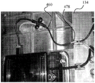
At various locations, the outer plastic cover 468 is peeled away to expose the shield 464. For example, fig. 48 depicts an outer stripped region 478 associated with location 474. The strip outer region 478 is placed in direct contact with the ramp carriage 134 at location 474. Typically, a protective cover 480 (see fig. 49) is then attached over the stripped area 478 to protect the stripped area 478 and ensure good contact between the shield 464 and the underlying metal components.
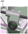
Depending on the location of the connection, a double screw protective cover, such as protective cover 480, or a single screw protective cover, such as protective cover 482 of fig. 50, may be used. In some embodiments, one or more of the protective covers are formed of plastic, while in other embodiments one or more of the protective covers are formed of metal to provide increased connectivity. Alternatively, the coaxial cable shield 464 can be soldered directly to other components or surfaces.
In some embodiments, only the connection locations where the protective covering 480/482 is provided are stripped away. Thus, in some embodiments, the cable is stripped at locations 472 and 476 of fig. 45, but at location 474 the cable is not stripped.
The coaxial cable shield 464 is thus connected to a metal component so that the shield 464 can be connected to a plurality of points without termination and so as to provide protection for the coaxial cable 460 where the outer plastic coating 468 is stripped. This ensures uninterrupted shield connections to all metal parts in the chassis assembly. The coaxial cable 460 is thus used to connect the shield to the ramp carriage 134, the height adjust carriage 142, the riving knife 116 and associated components, and the like.
A shield connection to angle indicator 130 (fig. 1) is also provided by location 472. As mentioned above, location 472 is in electrical communication with the ramp carriage 134, which is also shown in fig. 51. The ramp carriage 134 is correspondingly in electrical communication with the ramp clamp 133. Finally, when the ramp carriage 134 is locked by the ramp adjustment lock 132, the ramp clamp 133 is pressed into electrical communication with the angle indicator 130. Thus, the angle indicator 130 is placed in electrical communication with the shield 464.
The angle indicator 130 is electrically isolated from the workpiece support surface 108 by a non-conductive front plate 486. This allows the workpiece support surface 108 to be maintained at "neutral" while the angle indicator 130 is at "shield". In other embodiments, electrical isolation is provided to the bevel lock and the workpiece support surface by plastic spacers attached as a table, by using an all plastic front plate or a plastic front plate with small inserts for bevel clamping, or by using an all metal front plate with non-conductive spacers. If desired, the workpiece support surface 108 may be connected to ground to reduce interference with the sensing system from static electricity. Static electricity from the blades and components connected to the shield can be improved by connecting those components to ground through high resistance cables.
Since the bevel carriage 134 is suspended from the workpiece support surface 108, the support mechanism must also be insulated. As shown in fig. 52, the ramp carriage 134 includes a pair of tilt trunnions 488 (only one visible in fig. 52) that are pivotally supported by a pair of trunnion blocks 490 that are attached to the workpiece support surface 108. The trunnion block 490 is insulated from the inclined trunnion 488 by a pair of plastic trunnion inserts 492.
In some embodiments, the angle indicator 130 is connected to the shield or, alternatively or additionally, by a ramp carriage 134 or a height adjustment carriage 142. For example, fig. 45 shows the ramp carriage 134 connected to the "shield" at locations 472 and 476. Electrical communication with the locations 472 and 476 may be provided by a powder metallurgy bracket 496 (see fig. 51) in electrical communication with the height adjustment lever 484 and/or by a threaded rod bracket 498 in electrical communication with the height adjustment lever 484. Thus, while the PM brackets 496/498 provide additional strength (which allows other portions of the table saw 102 to be formed from lightweight metals), they can also provide good electrical communication between components.
As described above, the height adjust carriage 142 is connected to the shield 464. The drop arm frame 242 is in electrical communication with the height adjust carriage 142 via the rail bracket 203, respectively. Accordingly, the arbor shaft 240 and blade 118 are electrically isolated from the drop arm frame 242. As shown in fig. 53, the arbor 240 is electrically isolated from the drop arm frame 242 by a plastic bearing housing 500, wherein the plastic bearing housing 500 houses a bearing 501, the bearing 501 supporting a blade side 502 of the arbor 240. The pulley side 504 of the arbor 240 is supported by a bearing unit 506. The drop arm frame 242 includes an over-mold 508 that supports a rear bearing 510. Accordingly, the blade 118, as well as each of the arbor shaft 240, arbor nut 336, and blade washer 512/514, are electrically isolated from the drop arm frame 242. In an alternative embodiment, the bearings 510 are separated by a component (not shown) that can be incorporated into the rear bearing 510 either by press-fit, adhesive, over-molding, or by other techniques. The bearing can be formed of a non-conductive material (such as a ceramic material, as an example).
The arbor shaft 240 is further electrically isolated from the conductive belt 162 (fig. 15A) by the pulley 192. As depicted in fig. 53 and 54, the pulley 192 includes an inner core 520, an intermediate core 522, and an outer shell 524. A shim 526 is provided between the arbor shaft 240 and an inner shim lip 528 of the driven pulley 192. In another embodiment, more than one shim may be used in the system. A jam nut 530 maintains the pulley 192 on the arbor shaft 240.
The shim 526 provides proper alignment between the pulley 192 and the pulley 166. A motor end pulley 166 is attached to the motor assembly 160. The drive pulley 192 is attached to a drop arm assembly 194. Due to tolerance build-up, the two pulleys 192/166 may shift. Accordingly, in this embodiment, one of the pulleys is fixed and the other is adjustable. While shims are used in the embodiment of fig. 53, in other embodiments, the shims are replaced by a sliding collar or a collar that can be adjusted by rotation on an external thread. Other embodiments incorporate adjustable collars, movable collars with jackscrews in the pulley, skew planes on the pulley and shaft, c-turns instead of locknuts, adjustable multi-piece pulleys, or methods using pulleys of different sizes based on actual shaft offset measurements.
Returning to fig. 54, inner core 520 is wear resistant and may be formed of a conductive material. The inner core 520 includes an aperture 532 configured to couple with the arbor shaft 240, such as by threaded engagement. Other joining methods may also be used, such as splines, keys, press fit connections, and the like. The outer shell 524 is also resistant to wear and may be formed of a conductive material. The outer shell 524 includes an outer surface 534 configured to engage the band 162.
The intermediate core 522 is formed of a non-conductive material, which in one embodiment is insert molded plastic. The outer surface 536 of the inner core 520 and the inner surface 538 of the outer shell 524 include features to prevent sliding of the intermediate core 522 relative to the inner core 520 or the outer shell 524. Features include, but are not limited to: embossments, splines, dove-tails, protrusions, anti-slip structures, locking structures, etc.
As depicted in fig. 54A, in this embodiment, the outer shell 524 includes splines 540, which are dovetail shaped. The outer face exhibits an angle 542 of about 6 °. This provides increased locking, which is beneficial when using materials that exhibit different thermal expansion and contraction characteristics. Accordingly, when the intermediate core 522 is formed, a complementary dovetail structure is formed in the intermediate shell, as depicted in fig. 54. Thus, the outer and inner components of the pulley define a plurality of dovetail connections therebetween.
In other embodiments, electrical isolation between the arbor shaft 240 and the belt 162 is provided using an all plastic pulley, an anodized aluminum pulley, or a plastic over-molded pulley.
In some embodiments, a non-conductive tape is used in place of conductive tape 162. In this embodiment, a conductive pulley can be used with a non-conductive belt. In another embodiment, a conductive belt can be used with one conductive pulley and one non-conductive pulley.
The motor assembly 160 shown in fig. 6 is thus isolated from the arbor shaft 240 by the pulley 192. As depicted in fig. 6, the motor assembly 160 is also isolated by a pulley 166, the pulley 166 being made like a pulley 192 with a non-conductive intermediate core 580 between an inner core 582 and an outer shell 584.
Although the motor assembly 160 is thus electrically isolated from the arbor shaft 240 and blade 118, the motor can nevertheless generate electromagnetic interference. Accordingly, the motor assembly 160 is configured to reduce potential transmission of interfering electromagnetic energy. As depicted in fig. 6, power shaft 168 is radially supported within housing 586 by bearings 588. The other end of the power shaft 168 is radially supported within the motor gear housing 176 by a bearing 590. The offset drive shaft 164 containing the gear 170 is radially supported within the motor gear housing 176 by bearings 592. Bearing 594 is supported by a cover plate 596. A cover plate 596 is attached to the motor gear housing 176 and surrounds the gear 170 and positions the gear 170 to be driven by the armature pinion.
If all of the aforementioned components are made of metal, the motor assembly 160 will act like an antenna and transmit noise that can interfere with the sensing system. Specifically, the offset drive shaft 164 (also referred to as a gear shaft) and the bearings 588, 590, 592, and 594 each transmit noise that, if coupled to large components such as the motor gear housing 176, the motor casing 586, or the coverplate 596, would be transmitted in the vicinity of the sensing system if those components were all formed of metal. To reduce interference with the sensing system, the motor gear housing 176, casing 586 and cover plate 596 are therefore made of plastic, thereby significantly reducing the noise transmitted by the motor assembly 160. In an alternative embodiment, a non-metallic barrier is positioned between the shaft/bearing and the cover plate/gear housing.
In addition to interference from electrical noise, the motor assembly 160 also generates carbon dust, which can interfere with the operation of the sensing system including the CCP 262. For example, carbon dust from a common motor brush can accumulate on the components and can create a conductive path that will affect the sensing system. Accordingly, unlike a typical motor housing, the motor gear housing 176 is provided with a number of radial vents 610, as shown in fig. 55. The radial vents 610 turn the cooling air driven axially by the fan 612 (see fig. 6) and turn the air radially. Accordingly, any carbon entrained within the fan-driven air is forced in a direction away from the electrically isolated components comprising CCP262, thereby reducing the likelihood of carbon dust accumulating between the isolated components.
In some embodiments, additional reduction in electrical noise interference is achieved by incorporating an electronically commutated motor instead of an AC universal motor. Electronically commutated motors provide a more consistent noise level, which is more easily mitigated and the noise generated may be reduced. Other noise reduction features include the incorporation of ceramic bearings in place of plastic bearing spacers, the isolation of the gears from the pulley shaft with thermosets or thermoplastics, the partial isolation of the blades such as by using nonconductive blade washers, the incorporation of nonconductive couplings on the shaft, the incorporation of partially nonconductive cutter shafts, or the use of aluminum gear housings with isolated bearings.
The guide plate 114 of FIG. 1 is also configured to reduce potential interference with the sensing system. Specifically, the guide plate 114 is removably and movably attached to a guide rail 620/622 mounted to the workpiece support surface 108. The guide plate 114 is optionally in electrical communication with the workpiece support surface 108. Because the guide plate 114 is movable, the guide plate may contact the blade 118 or the riving knife 116 (or an associated pawl). To reduce the possibility of inadvertent contact that could affect the sensing system, the sides and top of the body portion of guide plate 114 are formed with spacer members 624, 626, 628, respectively. This allows the inner components and the end portions of the guide plate 114 to be formed of metal.
In one embodiment, one or more of the isolation members 624, 626, 628 can be removed and reinstalled by a user to allow for a customized jig or holder to be used with the tool. In another embodiment, a single spacer member is used. One spacer member may be "U" shaped to cover all three surfaces, or only one side of the guide plate.
In further embodiments, the body portion of the guide plate is injection molded with a release material. In some embodiments, the riving knife and associated pawl are signal isolated from the shield or are formed from a non-conductive material. In some embodiments, the spacer 628 is omitted and the recoil pawl is provided with a "lock-off" feature (similar to those common with the guard above) that locks off to prevent contact with the top of the fence. In further embodiments, the spacer member 628 is omitted and the guide plate is configured to extend only across the workpiece support surface 108 to a position where it cannot contact the recoil pawl.
Turning to fig. 58, the body portion 652 of the knob 650 includes two finger holes 660, a locking cam 662, and a lifting cam 664. The finger hole 660 provides an area for a user to obtain leverage to rotate the knob 650. In other embodiments, other geometries are provided to allow the user to gain leverage. In some embodiments, the body portion includes a coupling feature that allows a tool, such as a screwdriver, universal wrench, or other tool, to engage the knob 650 when rotation of the knob 650 is desired.
In one embodiment, the knob 650 and throat plate 122 are made of plastic to prevent interference with the sensing system. In areas subject to increased wear, metal inserts, such as insert 642, may be used to provide increased wear resistance. Such metal inserts are insulated from the workpiece support surface 108 by a plastic throat plate 122.
Removal of the throat plate 122 is often desirable in order to facilitate replacement of the blades 118 or other forming devices. Accordingly, the user simply rotates the knob 650 in the clockwise direction to urge the throat plate 122 upward as described above, and then removes the throat plate to expose the arbor nut 336, as depicted in fig. 21. Since the drop arm assembly 194 is solely supported by the latch 300 (see fig. 29), a user may inadvertently force the drop arm assembly 194 to move (disridge) when loosening or tightening the arbor nut 336. For example, when a blade wrench is used to turn the spindle nut in the tightening direction, a moment is generated which acts on the drop arm rail member 272 in a direction acting against the supporting force of the latch spring 308 and can cause unlocking. As described below, the arbor lock 250 is used to prevent such unlocking.
Referring to fig. 15B, once the throat plate 122 is removed, the user pushes the activation arm 252 in the direction of arrow 670. Referring now to fig. 21, when the activation arm 252 is pushed in the direction of arrow 670 of fig. 15B, the flange 248 compresses the spring 246 and forces the arbor lock 250 in the direction of arrow 672. The arbor lock 250 thus slides along the shoulder screws 258 and arbor shaft 240 by means of the guide slots 260 and arbor slots 256 guided by the shoulder screws 258.
As depicted in fig. 15B, when the arbor lock 250 is moved to the left, the narrow portion 674 of the arbor slot 256 moves into the notch 676 in the arbor 240, locking the arbor, which allows the user to rotate the arbor nut 336 (see fig. 21).
Additionally, as depicted in fig. 60, the locking ramp 254 is positioned on the locking ramp 364. Because the locking ramp 364 is part of the pyrotechnic housing 332 mounted to the height adjustment carriage 142, the drop arm assembly 194 cannot be unlocked from the latch 300 even when the arbor nut 336 is tightened. In alternative embodiments, the knife shaft lock is interconnected with other components attached to the height adjust carriage 142 or part of the height adjust carriage 142.
Removal of the throat plate 122 also allows the user to reset the drop arm assembly 194 in the event that the drop arm assembly 194 is unlocked or otherwise unlatched from the latch 300, either due to the saw control unit. As shown in fig. 61, the drop arm assembly 194 can be reset by: the reset lever 416 is first pushed in the direction of arrow 678, which moves the upper and lower latches 404, 402 as described above with respect to fig. 36, allowing the drop arm assembly 194 to be moved up the track. The user then positions the blade wrench 680 about the arbor nut 336 or arbor 240 to pull the drop arm assembly 194 back to the locked position, as described above with respect to fig. 26-29.
In some embodiments, a push bar or some other removable tool is used to lift the drop arm assembly 194. In further embodiments, the handle is provided on the drop arm assembly itself. In yet further embodiments, the drop arm assembly 194 is automatically lifted after unlocking, such as by using energy stored during movement of the drop arm assembly 194. In some embodiments, some of the energy from the motion of the drop arm assembly is stored in a spring positioned at surface 374.
The HMI unit 124 of FIG. 1 is shown in greater detail in FIG. 62. The HMI unit 124 includes a housing 700, an access point 702, shown herein as a Near Field Communication (NFC) access point, and several status indicators 704. Other types of communication protocols, such as bluetooth, bluetooth peak, Wi-Fi, data protocol, mobile protocol, Ultra Wideband (UWB) protocol, or any frequency band are possible. The housing 700 protects other components of the HMI unit 124 while providing user access to the components of the HMI unit 124. The NFC access point 702 is a location where an electronic device, such as a smartphone, can be located to transfer data from the transceiver of the HMI unit 124 to the smartphone. For this purpose, the user smart phone is provided with an application comprising a communication protocol. The user can use the NFC access point 702 to obtain the current status of the table saw 102 as well as unique identification information for the table saw. The application can then be used to obtain maintenance recommendations, a reset procedure or a troubleshooting procedure, and to provide for registration of the table saw. Applications can also lock or unlock the system. For example, an application is used to lock or unlock one or more of the bypass switch and the motor power switch using a personal identification number or code.
Status indicators 704 are used to provide a desired warning or status indicator to the user. In some embodiments, the status indicator 704 indicates available power, a bypass security system, a security or system error that can be fixed by the user, and a security or system error that can be fixed by the service center. In different embodiments, more or fewer status indicators 704 are provided. The configuration of the HMI unit 124 enables the status indicator 704 to be viewed even in bright daylight, as discussed further with reference to fig. 63.
As shown in fig. 63, the status indicator 704 is illuminated by four LEDs 706 on a Printed Circuit Board (PCB) 708. In some embodiments, each of the LEDS 706 is provided as a colored LED having a color different from the other LEDS. An NFC antenna 710 is also disposed on the PCB 708. The PCB 708 is supported by a support 712 attached to the housing 700. Spacers 714 are attached to the support 712 by clips 716. The spacer 714 includes several recesses 718 including openings (not shown) at lower portions of the recesses 718, the recesses 718 receiving respective ones of the LEDs 706. Spacers 714 provide suitable spacing between the LEDs and diffuser (diffuser) 720, as well as suitable spacing between NFC antenna 710 and smartphone access point 702. The recesses 718 of the spacers 714 also prevent light penetration (light blue) between the different colored LEDs 706. The recess 718 of the spacer 714 also includes one or more openings or passages 719. The pathway directs dust away from the LED706, thereby preventing the LED706 from being covered.
The diffuser 720 includes several lenses 722, each lens being associated with a respective one of the recesses 718. Diffuser 720 maintains LED brightness while diffusing light to appear uniform across the exposed surface. Diffuser 720 is made of a material that is resistant to scratching and chipping.
While some components of the table saw 102 are thus configured to provide ease of access or use, access or use of some components by a user is not desired. For example, during assembly of the table saw 102 and in some cases, the PCB 452 must be electronically accessible by a service technician, but should not be accessible by a user. Accordingly, the USB port 458 is positioned to provide access for a technician while restricting user access, as discussed initially with reference to fig. 64.
In FIG. 64, the table saw 102 is depicted with a zero bevel angle. Accordingly, the dust port 730 is positioned in the substrate housing 106 adjacent a lower end portion of the dust port access slot 732. The dust port 730 is part of a dust cover 734 attached to the ramp carriage 134 (not visible in fig. 64). In this position, both the USB port 458 and the outer housing 454 of fig. 42 are not visible to the user.
FIG. 65 depicts a rear view of the table saw 103 when the table saw 102 is positioned at an oblique angle of forty-five degrees (the dust cover 734 is not depicted in this view). In this position, the outer housing 454 and the USB port 458 are viewable through the dust port access slot 732. Accordingly, the USB port 458 is accessible by a service technician. However, since the user is not expected to often look through the dust port access slot 732 at the angle depicted in fig. 65, the user will not typically see the USB port 458. Accordingly, in most cases, the USB port 458 is shielded from the user.
In some embodiments, access to USB port 458 is also protected, such as by providing a protective plastic or rubber stopper 736 (fig. 66) or cover 738 that is tightened with tamper resistant screw 740 (fig. 67). In some embodiments, the outer housing 454 must be removed to provide access to the PCB 452.
While the disclosure has been illustrated and described in detail in the drawings and foregoing description, the same is to be considered as illustrative and not restrictive in character. It should be understood that only the preferred embodiment has been shown and that all changes, modifications and further applications that come within the spirit of the disclosure are desired to be protected.
Claims (13)
1. A power tool assembly comprising:
a drop arm assembly rotatably supporting the arbor and movable between a first drop arm position and a second drop arm position;
an actuating device configured to apply a force to the drop arm assembly sufficient to move the drop arm assembly from the first drop arm position to the second drop arm position when the drop arm assembly is in the first drop arm assembly position;
a saw control unit assembly configured to control the actuation device to apply a force to the drop arm assembly when an unsafe condition is sensed;
a motor operatively connected to the arbor by a gear; and
a gear housing the gear, the gear housing formed of a non-conductive material, wherein:
a power shaft of the motor defines a power shaft axis;
the fan is arranged on a power shaft of the motor; and is
The gear housing further includes a plurality of radial vents, the gear housing and the radial vents configured to exhaust all air driven by the fan radially outward from the axis such that no air contacts the forming device when the forming device is mounted to the arbor.
2. The power tool assembly of claim 1, wherein the gear housing extends over the fan.
3. The power tool assembly of claim 1, wherein the non-conductive material is plastic.
4. The power tool assembly of claim 1, further comprising:
an offset driveshaft operatively connected to the power shaft through the gear and at least partially within the gear housing; and
at least one first bearing rotationally supporting the offset drive shaft and located within the gear housing.
5. The power tool assembly of claim 4, further comprising:
a cover plate enclosing the gear within the gear housing, the cover plate being made of a non-conductive material.
6. The power tool assembly of claim 5, further comprising:
at least one second bearing rotationally supporting the offset drive shaft, the at least one second bearing being directly supported by the cover plate.
7. A power tool assembly comprising:
a vertical arm component which can rotatably support the cutter shaft;
a saw control unit assembly configured to place the drop arm assembly in a safe condition when an unsafe condition is sensed;
a motor including a power shaft operatively connected to the arbor; and
a housing partially enclosing the motor, the housing including a plurality of radial vents configured to vent air radially outward from an axis defined by the power shaft such that air exiting the housing does not contact the forming device when the forming device is mounted to the arbor.
8. The power tool assembly of claim 7, wherein the housing is formed of a non-conductive material.
9. The power tool assembly of claim 8, wherein the housing extends over a fan mounted on a power shaft of the motor.
10. The power tool assembly of claim 9, wherein the non-conductive material is plastic.
11. The power tool assembly of claim 9, further comprising:
an offset driveshaft operably connected to the power shaft by a gear and located at least partially within the housing; and
at least one first bearing rotationally supporting the offset drive shaft and located within the housing.
12. The power tool assembly of claim 11, further comprising:
a cover plate made of a non-conductive material; and
at least one second bearing rotationally supporting the offset drive shaft, the at least one second bearing being directly supported by the cover plate.
13. The power tool assembly of claim 12, further comprising:
a gear operatively connected to the arbor and the power shaft, the gear received by the housing.
Applications Claiming Priority (7)
| Application Number | Priority Date | Filing Date | Title |
|---|---|---|---|
| US201562132004P | 2015-03-12 | 2015-03-12 | |
| US201562131977P | 2015-03-12 | 2015-03-12 | |
| US62/132004 | 2015-03-12 | ||
| US62/131977 | 2015-03-12 | ||
| US15/060,746 US10493543B2 (en) | 2015-03-12 | 2016-03-04 | Power tool motor with reduced electrical noise |
| US15/060746 | 2016-03-04 | ||
| PCT/US2016/022027 WO2016145322A1 (en) | 2015-03-12 | 2016-03-11 | Power tool motor with reduced electrical noise |
Publications (2)
| Publication Number | Publication Date |
|---|---|
| CN107548331A CN107548331A (en) | 2018-01-05 |
| CN107548331B true CN107548331B (en) | 2020-08-21 |
Family
ID=56879743
Family Applications (1)
| Application Number | Title | Priority Date | Filing Date |
|---|---|---|---|
| CN201680027409.XA Active CN107548331B (en) | 2015-03-12 | 2016-03-11 | Electric tool motor with reduced electrical noise |
Country Status (6)
| Country | Link |
|---|---|
| US (1) | US10493543B2 (en) |
| EP (1) | EP3268184B1 (en) |
| KR (1) | KR102058403B1 (en) |
| CN (1) | CN107548331B (en) |
| AU (1) | AU2016228821B2 (en) |
| WO (1) | WO2016145322A1 (en) |
Family Cites Families (166)
| Publication number | Priority date | Publication date | Assignee | Title |
|---|---|---|---|---|
| US2569914A (en) | 1948-08-06 | 1951-10-02 | Appleton Electric Co | Cover clamp |
| US2719547A (en) * | 1952-03-01 | 1955-10-04 | Gjerde Arne | Universally adjustable underbench saw |
| US3490637A (en) | 1968-06-24 | 1970-01-20 | Robert M Pope | Utility marker box |
| US3908139A (en) * | 1974-06-10 | 1975-09-23 | Singer Co | Portable power tools |
| US3909987A (en) | 1974-12-18 | 1975-10-07 | Sr Donald W Maccarthy | Idler pulley adjustment device |
| US4105055A (en) * | 1976-09-01 | 1978-08-08 | Robert Brenta | Portable workshop |
| DE2654521A1 (en) | 1976-12-01 | 1978-06-08 | Mey Kg Maschf Mafell | NAIL DEVICE |
| DE3306841A1 (en) | 1983-02-26 | 1984-08-30 | Mafell Maschinenfabrik Rudolf Mey GmbH & Co KG, 7238 Oberndorf | METHOD FOR PROCESSING A MATERIAL OR WORKPIECE BY MEANS OF ULTRASOUND AND DEVICE FOR IMPLEMENTING THE METHOD |
| IT8322561V0 (en) | 1983-08-02 | 1983-08-02 | Black & Decker Inc | TOOL HOLDER ARM TO BE APPLIED ON A BEARING ON SUPPORTING COLUMNS AND, EQUIPPED WITH GUIDE MEANS, IN PARTICULAR FOR CORNER SQUARING MACHINES. |
| JPS60142345U (en) | 1984-03-02 | 1985-09-20 | トヨタ自動車株式会社 | V-belt tension adjustment mechanism |
| JPS6114837A (en) | 1984-06-27 | 1986-01-23 | Nissan Motor Co Ltd | Facility abnormality reporting system |
| US4631433A (en) * | 1985-05-06 | 1986-12-23 | General Electric Company | Plastic end shield with thermal barrier for dynamoelectric machines |
| CA1223793A (en) * | 1986-06-23 | 1987-07-07 | Jacques Ducharme | Scoring saw |
| US4893946A (en) | 1989-05-15 | 1990-01-16 | Amkor Industries, Inc. | Roller for spinning frame |
| US5006740A (en) * | 1990-06-13 | 1991-04-09 | Milwaukee Electric Tool Corporation | Insulated cooling boot for power tool |
| US5090126A (en) | 1990-07-25 | 1992-02-25 | Higgins Toney D | Rotary tool quick acting retention device |
| US5132629A (en) | 1991-02-25 | 1992-07-21 | Clinton Instrument Company | Apparatus for testing the insulation of an electrical conductor passing through an electrode |
| US5123317A (en) | 1991-03-20 | 1992-06-23 | Ryobi Motor Products Corp. | Support structure for a table saw blade assembly |
| US5177871A (en) | 1991-10-08 | 1993-01-12 | Textron Inc. | Power tool belt tension system |
| US5163883A (en) | 1991-12-04 | 1992-11-17 | General Motors Corporation | Pulley with integral fastener and spacer |
| US5268607A (en) * | 1992-09-09 | 1993-12-07 | Webster Plastics | Molded resin motor housing |
| JPH07298551A (en) | 1994-04-26 | 1995-11-10 | Hitachi Ltd | Alternator for vehicle |
| DE29513700U1 (en) * | 1995-08-25 | 1996-09-19 | Siemens Ag | Motor-gear drive unit, in particular for a motor vehicle window regulator drive or the like. |
| US5676319A (en) | 1995-10-23 | 1997-10-14 | Stiggins; Kendy Lee | Garbage disposal system |
| US5734214A (en) * | 1995-11-09 | 1998-03-31 | Ametek, Inc. | Molded through-flow motor assembly |
| DE69835973T2 (en) | 1997-04-29 | 2007-08-30 | Black & Decker Inc., Newark | table saw |
| US6111643A (en) | 1997-10-28 | 2000-08-29 | Reliance Electric Industrial Company | Apparatus, system and method for determining wear of an article |
| US6044964A (en) | 1998-02-26 | 2000-04-04 | Sony Corporation | Multidirection belt conveyor |
| US6272960B1 (en) | 1998-06-03 | 2001-08-14 | Black & Decker Inc. | Chop saw |
| US5970835A (en) | 1998-09-10 | 1999-10-26 | Black & Decker Inc. | Throat plate for a tool |
| JP2000156124A (en) | 1998-11-19 | 2000-06-06 | Furukawa Electric Co Ltd:The | Twisted pair of wires and pair cable braided of the same |
| US6536536B1 (en) | 1999-04-29 | 2003-03-25 | Stephen F. Gass | Power tools |
| US6109157A (en) | 1999-06-09 | 2000-08-29 | S-B Power Tool Company | Arbor locking mechanism |
| US6530303B1 (en) | 1999-06-10 | 2003-03-11 | Black & Decker Inc. | Table saw |
| US6255751B1 (en) * | 1999-09-09 | 2001-07-03 | Torex Corporation | Integrated rotary servo actuator |
| CN100343030C (en) | 1999-10-01 | 2007-10-17 | Sd3有限责任公司 | Safety systems for power equipment |
| US7284467B2 (en) | 2000-08-14 | 2007-10-23 | Sd3, Llc | Apparatus and method for detecting dangerous conditions in power equipment |
| AU785422B2 (en) | 1999-10-01 | 2007-05-03 | Sawstop Holding Llc | Safety systems for power equipment |
| US7350444B2 (en) * | 2000-08-14 | 2008-04-01 | Sd3, Llc | Table saw with improved safety system |
| US7231856B2 (en) | 2001-06-13 | 2007-06-19 | Sd3, Llc | Apparatus and method for detecting dangerous conditions in power equipment |
| US6877410B2 (en) | 2000-09-29 | 2005-04-12 | Sd3, Llc | Miter saw with improved safety system |
| US6945148B2 (en) | 2000-09-29 | 2005-09-20 | Sd3, Llc | Miter saw with improved safety system |
| US7210383B2 (en) | 2000-08-14 | 2007-05-01 | Sd3, Llc | Detection system for power equipment |
| US20050041359A1 (en) | 2003-08-20 | 2005-02-24 | Gass Stephen F. | Motion detecting system for use in a safety system for power equipment |
| US7789002B2 (en) * | 2000-09-29 | 2010-09-07 | Sd3, Llc | Table saw with improved safety system |
| US8061245B2 (en) | 2000-09-29 | 2011-11-22 | Sd3, Llc | Safety methods for use in power equipment |
| US7055417B1 (en) | 1999-10-01 | 2006-06-06 | Sd3, Llc | Safety system for power equipment |
| US9724840B2 (en) | 1999-10-01 | 2017-08-08 | Sd3, Llc | Safety systems for power equipment |
| US6945149B2 (en) | 2001-07-25 | 2005-09-20 | Sd3, Llc | Actuators for use in fast-acting safety systems |
| US7481140B2 (en) | 2005-04-15 | 2009-01-27 | Sd3, Llc | Detection systems for power equipment |
| US7024975B2 (en) | 2000-08-14 | 2006-04-11 | Sd3, Llc | Brake mechanism for power equipment |
| US7171879B2 (en) | 2001-07-02 | 2007-02-06 | Sd3, Llc | Discrete proximity detection system |
| US7377199B2 (en) | 2000-09-29 | 2008-05-27 | Sd3, Llc | Contact detection system for power equipment |
| US10589366B2 (en) | 2010-02-19 | 2020-03-17 | Sawstop Holding Llc | Table saw insert with lock-down mechanism |
| US20030037651A1 (en) | 2001-08-13 | 2003-02-27 | Gass Stephen F. | Safety systems for power equipment |
| US20030131703A1 (en) * | 2002-01-16 | 2003-07-17 | Gass Stephen F. | Apparatus and method for detecting dangerous conditions in power equipment |
| US6994004B2 (en) | 2000-09-29 | 2006-02-07 | Sd3, Llc | Table saw with improved safety system |
| US7350445B2 (en) | 2003-08-20 | 2008-04-01 | Sd3, Llc | Brake cartridge for power equipment |
| US6920814B2 (en) | 2000-08-14 | 2005-07-26 | Sd3, Llc | Cutting tool safety system |
| US6857345B2 (en) | 2000-08-14 | 2005-02-22 | Sd3, Llc | Brake positioning system |
| US7707920B2 (en) | 2003-12-31 | 2010-05-04 | Sd3, Llc | Table saws with safety systems |
| US7197969B2 (en) | 2001-09-24 | 2007-04-03 | Sd3, Llc | Logic control with test mode for fast-acting safety system |
| US7509899B2 (en) * | 2000-08-14 | 2009-03-31 | Sd3, Llc | Retraction system for use in power equipment |
| US7225712B2 (en) | 2000-08-14 | 2007-06-05 | Sd3, Llc | Motion detecting system for use in a safety system for power equipment |
| US6957601B2 (en) | 2000-08-14 | 2005-10-25 | Sd3, Llc | Translation stop for use in power equipment |
| US6880440B2 (en) | 2000-09-29 | 2005-04-19 | Sd3, Llc | Miter saw with improved safety system |
| US7137326B2 (en) | 2000-08-14 | 2006-11-21 | Sd3, Llc | Translation stop for use in power equipment |
| US7472634B2 (en) | 2003-08-20 | 2009-01-06 | Sd3, Llc | Woodworking machines with overmolded arbors |
| US7077039B2 (en) | 2001-11-13 | 2006-07-18 | Sd3, Llc | Detection system for power equipment |
| US7536238B2 (en) | 2003-12-31 | 2009-05-19 | Sd3, Llc | Detection systems for power equipment |
| US7308843B2 (en) | 2000-08-14 | 2007-12-18 | Sd3, Llc | Spring-biased brake mechanism for power equipment |
| US9981326B2 (en) | 2008-08-18 | 2018-05-29 | Sawstop Holding Llc | Table saw |
| US7100483B2 (en) | 2000-08-14 | 2006-09-05 | Sd3, Llc | Firing subsystem for use in a fast-acting safety system |
| US7600455B2 (en) * | 2000-08-14 | 2009-10-13 | Sd3, Llc | Logic control for fast-acting safety system |
| US7000514B2 (en) | 2001-07-27 | 2006-02-21 | Sd3, Llc | Safety systems for band saws |
| US7353737B2 (en) | 2001-08-13 | 2008-04-08 | Sd3, Llc | Miter saw with improved safety system |
| US7290472B2 (en) | 2002-01-14 | 2007-11-06 | Sd3, Llc | Miter saw with improved safety system |
| US7098800B2 (en) | 2003-03-05 | 2006-08-29 | Sd3, Llc | Retraction system and motor position for use with safety systems for power equipment |
| US6573625B2 (en) * | 2000-03-29 | 2003-06-03 | Asmo Co., Ltd. | Motor device having water-proof brush holder |
| DE20007037U1 (en) | 2000-04-17 | 2000-07-20 | Mafell Ag | Table saw |
| US6826988B2 (en) | 2000-09-29 | 2004-12-07 | Sd3, Llc | Miter saw with improved safety system |
| US6813983B2 (en) | 2000-09-29 | 2004-11-09 | Sd3, Llc | Power saw with improved safety system |
| JP3815211B2 (en) | 2000-11-24 | 2006-08-30 | 松下電工株式会社 | Electric circular saw |
| DE10125582A1 (en) * | 2001-05-25 | 2002-12-05 | Webasto Vehicle Sys Int Gmbh | driving device |
| CA2453352C (en) | 2001-07-11 | 2008-12-16 | Black & Decker Inc. | Power tool safety mechanisms |
| US6986185B2 (en) | 2001-10-30 | 2006-01-17 | Applied Materials Inc. | Methods and apparatus for determining scrubber brush pressure |
| JP2003153583A (en) | 2001-11-12 | 2003-05-23 | Denso Corp | Monitor of dc servo motor and monitor system of robot |
| JP3641238B2 (en) * | 2001-12-26 | 2005-04-20 | アスモ株式会社 | Assembling method of brush holding device and rotating electric machine |
| US6898854B2 (en) | 2002-06-07 | 2005-05-31 | Black & Decker Inc. | Modular power tool |
| US6900728B2 (en) | 2002-07-29 | 2005-05-31 | Home Depot U.S.A., Inc. | System to detect user entry into a defined danger zone |
| GB0218198D0 (en) * | 2002-08-06 | 2002-09-11 | Johnson Electric Sa | Fan |
| US6808333B2 (en) | 2002-10-30 | 2004-10-26 | Cnh Canada, Ltd | Pivot pin assembly |
| US6748838B1 (en) | 2002-12-06 | 2004-06-15 | Chang Chin-Chin | Table saw having a rotation structure |
| DE10261791A1 (en) | 2002-12-23 | 2004-07-15 | Robert Bosch Gmbh | Device for protection against accidental contact and method for protecting against contact with a moving part |
| KR101046666B1 (en) | 2002-12-25 | 2011-07-06 | 에이씨티 엘에스아이 인크. | Capacitive Detect Proximity Sensors |
| US7698975B2 (en) * | 2003-01-31 | 2010-04-20 | Techtronic Power Tools Technology Limited | Table saw with cutting tool retraction system |
| US20040194594A1 (en) | 2003-01-31 | 2004-10-07 | Dils Jeffrey M. | Machine safety protection system |
| US7290474B2 (en) * | 2003-04-29 | 2007-11-06 | Black & Decker Inc. | System for rapidly stopping a spinning table saw blade |
| US6922153B2 (en) * | 2003-05-13 | 2005-07-26 | Credo Technology Corporation | Safety detection and protection system for power tools |
| JP3903956B2 (en) * | 2003-05-23 | 2007-04-11 | 日産自動車株式会社 | Multi-axis multilayer motor |
| DE10329826A1 (en) | 2003-06-27 | 2005-01-13 | Festool Gmbh | sanding pad |
| US20050081318A1 (en) * | 2003-10-20 | 2005-04-21 | Boutilier Wayne A. | Scraper and safety sheath |
| DE202004012468U1 (en) | 2003-11-21 | 2004-11-04 | Festool Gmbh | Table saw has carriage to support work for movement with respect to circular saw blade and drive shaft with handle having saw control switch |
| EP1563969B1 (en) | 2004-02-13 | 2007-03-07 | Festool GmbH | Dust collector for a router |
| US7134373B1 (en) | 2004-02-23 | 2006-11-14 | James Perry Vice | Throat insert for a table saw |
| KR100529377B1 (en) | 2004-03-15 | 2005-11-17 | 한국전력공사 | Partial discharge monitoring system of high voltage rotating machine |
| US20060032355A1 (en) | 2004-08-11 | 2006-02-16 | Wang Wang T | Cutting device for dual-blade cutting tool |
| US20060201300A1 (en) * | 2005-03-11 | 2006-09-14 | Schwaiger Barry M | Cutting tool and parts and accessories therefor |
| US8006596B2 (en) | 2005-03-11 | 2011-08-30 | Walter Meier (Manufacturing) Inc. | Cutting tool and parts and accessories therefor |
| US7628101B1 (en) | 2006-03-13 | 2009-12-08 | Power Tool Institute | Pyrotechnic drop mechanism for power tools |
| FR2883606B1 (en) | 2005-03-24 | 2010-03-19 | Snpe Materiaux Energetiques | PYROTECHNIC ACTUATOR WITH PRESSURE REGULATING MEMBER |
| US7804204B1 (en) | 2005-05-19 | 2010-09-28 | Power Tool Institute | Capacitive sensing system for power cutting tool |
| DE102005060324B4 (en) | 2005-12-16 | 2021-03-18 | Robert Bosch Gmbh | Detection of the wear of a motor control |
| TWI280184B (en) * | 2006-03-23 | 2007-05-01 | Chi Whi Ind Inc | Box knife |
| TWM297804U (en) | 2006-03-30 | 2006-09-21 | Durq Machinery Corp | Steady lifting and lowering structure for the saw blade of bench saw |
| US7459817B2 (en) * | 2006-08-15 | 2008-12-02 | Bombardier Transportation Gmbh | Semi-enclosed AC motor |
| CN200958682Y (en) | 2006-09-15 | 2007-10-10 | 东莞市凌峰信息科技有限公司 | Intelligent personal safety protector |
| CN201012414Y (en) | 2007-01-29 | 2008-01-30 | 圣杰机器工业股份有限公司 | Bench saw riving knife adjusting structure |
| KR101275733B1 (en) | 2007-05-07 | 2013-06-14 | (주)신한전기 | electronic expansion valve |
| US8618943B2 (en) | 2007-05-24 | 2013-12-31 | Cutsforth, Inc. | Brush holder assembly monitoring apparatus, assembly, system and method |
| US20090314510A1 (en) | 2008-01-11 | 2009-12-24 | Kukowski Thomas R | Elastomeric Conductors and Shields |
| JP2010023186A (en) * | 2008-07-18 | 2010-02-04 | Makita Corp | Cutter |
| US8127648B2 (en) * | 2008-07-31 | 2012-03-06 | Robert Bosch Gmbh | Table saw guard system |
| CN201239972Y (en) | 2008-08-08 | 2009-05-20 | 山东工友集团股份有限公司 | Belt stretcher for scribing sawblade of precise plate cutting saw |
| US7739934B2 (en) | 2008-09-08 | 2010-06-22 | Power Tool Institute | Detection system for power tool |
| EP2166647B1 (en) * | 2008-09-19 | 2018-04-11 | ABB Schweiz AG | Self-ventilated traction motor |
| US8122798B1 (en) | 2008-11-19 | 2012-02-28 | Power Tool Institute | Power cutting tool with proximity sensing system |
| US8919231B2 (en) | 2008-11-19 | 2014-12-30 | Power Tool Institute | Safety mechanisms for power tools |
| US8082825B2 (en) | 2009-06-09 | 2011-12-27 | Butler David J | Health and safety system for a table saw |
| DE102009027317B4 (en) | 2009-06-30 | 2019-12-05 | Robert Bosch Gmbh | Tool |
| DE102010025586B4 (en) * | 2009-07-01 | 2021-04-15 | Johnson Electric International AG | Power tool |
| US8245612B2 (en) | 2009-08-26 | 2012-08-21 | Robert Bosch Gmbh | Table saw with swing arm support |
| US8250957B2 (en) | 2009-08-26 | 2012-08-28 | Robert Bosch Gmbh | Table saw with linkage drop system |
| US10029386B2 (en) | 2009-08-26 | 2018-07-24 | Robert Bosch Tool Corporation | Table saw with positive locking mechanism |
| US8327744B2 (en) | 2009-08-26 | 2012-12-11 | Robert Bosch Gmbh | Table saw with reset mechanism |
| US8291801B2 (en) | 2009-08-26 | 2012-10-23 | Robert Bosch Gmbh | Table saw with ratchet mechanism |
| US8297159B2 (en) | 2009-08-26 | 2012-10-30 | Robert Bosch Gmbh | Table saw with dropping blade |
| US8210076B2 (en) | 2009-08-26 | 2012-07-03 | Robert Bosch Gmbh | Table saw with mechanical fuse |
| US9079258B2 (en) | 2009-08-26 | 2015-07-14 | Robert Bosch Gmbh | Table saw with belt stop |
| US8316748B2 (en) | 2009-08-26 | 2012-11-27 | Robert Bosch Gmbh | Table saw with alignment plate |
| US8186258B2 (en) | 2009-08-26 | 2012-05-29 | Robert Bosch Gmbh | Table saw with actuator reset mechanism |
| US8286537B2 (en) | 2009-08-26 | 2012-10-16 | Robert Bosch Gmbh | Table saw with pressure operated actuator |
| KR100981680B1 (en) | 2009-09-15 | 2010-09-10 | 조지현 | Manhole cover having lock and opening device |
| US10384281B2 (en) * | 2012-03-02 | 2019-08-20 | Sawstop Holding Llc | Actuators for power tool safety systems |
| WO2011043746A1 (en) | 2009-10-07 | 2011-04-14 | Bahtiyar Tasyagan | A reserve bullet store |
| CN101733478B (en) | 2009-12-03 | 2014-01-08 | 青岛地恩地机电科技股份有限公司 | Bench saw transmission mechanism |
| US8648016B2 (en) | 2010-02-08 | 2014-02-11 | Robert Bosch Gmbh | Array with extended dynamic range and associated method |
| KR101179734B1 (en) | 2010-03-19 | 2012-09-04 | 룰런즈라버코리아 주식회사 | Environment friendly and electrically conductive belt and method for preparing the same |
| CN201677207U (en) | 2010-05-13 | 2010-12-22 | 河南省中原内配股份有限公司 | Counting and controlling device |
| US8534174B2 (en) | 2010-09-27 | 2013-09-17 | Power Tool Institute | Pyrotechnic actuator and power cutting tool with safety reaction system having such pyrotechnic actuator |
| US8726773B2 (en) * | 2010-10-19 | 2014-05-20 | Robert Bosch Gmbh | Table saw having airflow apparatus |
| CN102346466A (en) | 2011-06-17 | 2012-02-08 | 武汉理工大学 | Remote monitoring device for metal sawing machines |
| KR101266475B1 (en) | 2011-07-07 | 2013-05-27 | 연세대학교 산학협력단 | cable fault diagnostic system and method |
| US8972219B2 (en) | 2012-02-22 | 2015-03-03 | General Electric Company | Method and system of monitoring electrical brushes |
| DE102012206863A1 (en) | 2012-04-25 | 2013-10-31 | Robert Bosch Gmbh | Diagnostic device for diagnosis of commutator motor, has evaluation unit to determine current wear condition of one of brushes based on multiple high-frequency voltage peaks during operation of commutator motor |
| US20140107853A1 (en) | 2012-06-26 | 2014-04-17 | Black & Decker Inc. | System for enhancing power tools |
| US8943937B2 (en) | 2012-09-28 | 2015-02-03 | Robert Bosch Gmbh | Power tool with circuit for sensing contact between an implement and an object |
| US9702916B2 (en) | 2012-09-28 | 2017-07-11 | Robert Bosch Tool Corporation | System and method for reducing false positive detection between a human and a moving implement in a power tool |
| US20140182430A1 (en) | 2012-12-31 | 2014-07-03 | Robert Bosch Gmbh | Saw Device with Detection System |
| US9252643B2 (en) | 2013-03-14 | 2016-02-02 | Cutsforth, Inc. | System and method for monitoring the status of one or more components of an electrical machine |
| US9517516B2 (en) | 2013-03-14 | 2016-12-13 | Robert Bosch Tool Corporation | Blade drop power tool with dust management |
| US9511429B2 (en) | 2013-03-15 | 2016-12-06 | Robert BoschTool Corporation | Blade drop for power device and method of manufacturing thereof |
| CN203502787U (en) | 2013-10-15 | 2014-03-26 | 丽水学院 | Remote wireless fault diagnosis device of metal band sawing machine |
| CN203786187U (en) | 2014-04-29 | 2014-08-20 | 重庆勤智科技有限公司 | Online generator carbon brush comprehensive current-monitoring apparatus |
| CN104049244B (en) | 2014-06-23 | 2017-01-04 | 中国人民解放军63698部队 | The radar velocity measurement machine carbon brush abrasion recognition methods analyzed based on temporal signatures value |
| US10189098B2 (en) * | 2015-03-12 | 2019-01-29 | Robert Bosch Tool Corporation | Diagnostic and maintenance operation for a saw |
-
2016
- 2016-03-04 US US15/060,746 patent/US10493543B2/en active Active
- 2016-03-11 CN CN201680027409.XA patent/CN107548331B/en active Active
- 2016-03-11 WO PCT/US2016/022027 patent/WO2016145322A1/en active Application Filing
- 2016-03-11 AU AU2016228821A patent/AU2016228821B2/en active Active
- 2016-03-11 EP EP16762606.8A patent/EP3268184B1/en active Active
- 2016-03-11 KR KR1020177028083A patent/KR102058403B1/en active IP Right Grant
Also Published As
| Publication number | Publication date |
|---|---|
| EP3268184A4 (en) | 2019-03-20 |
| AU2016228821A1 (en) | 2017-10-05 |
| AU2016228821B2 (en) | 2018-12-13 |
| US10493543B2 (en) | 2019-12-03 |
| KR102058403B1 (en) | 2019-12-24 |
| US20160263679A1 (en) | 2016-09-15 |
| KR20170123687A (en) | 2017-11-08 |
| WO2016145322A1 (en) | 2016-09-15 |
| CN107548331A (en) | 2018-01-05 |
| EP3268184B1 (en) | 2021-06-16 |
| EP3268184A1 (en) | 2018-01-17 |
Similar Documents
| Publication | Publication Date | Title |
|---|---|---|
| US10507537B2 (en) | Method of operating a power tool with a protected coupling plate | |
| CN107530899B (en) | Electric tool with plumbing arm rail bracket | |
| CN107548338B (en) | Power tool assembly and method of positioning an actuator in a power tool assembly | |
| CN107530900B (en) | Power tool with pyrotechnic lockout and method of operating same | |
| CN107530796B (en) | Power tool with improved belt tensioning | |
| CN107530797B (en) | Bench saw with electrically isolated arbor | |
| CN107548328B (en) | Plumbing arm resetting method | |
| CN107567364B (en) | Power tool with protected circuit board orientation | |
| CN107530799B (en) | Table saw with pulley alignment mechanism | |
| EP3268183B1 (en) | Power tool drop arm with offset ribbing | |
| EP3268182B1 (en) | Saw assembly with arbor lock and method of positioning a saw blade on a table saw assembly | |
| CN107548331B (en) | Electric tool motor with reduced electrical noise |
Legal Events
| Date | Code | Title | Description |
|---|---|---|---|
| PB01 | Publication | ||
| PB01 | Publication | ||
| SE01 | Entry into force of request for substantive examination | ||
| SE01 | Entry into force of request for substantive examination | ||
| GR01 | Patent grant | ||
| GR01 | Patent grant |