US4631433A - Plastic end shield with thermal barrier for dynamoelectric machines - Google Patents
Plastic end shield with thermal barrier for dynamoelectric machines Download PDFInfo
- Publication number
- US4631433A US4631433A US06/730,889 US73088985A US4631433A US 4631433 A US4631433 A US 4631433A US 73088985 A US73088985 A US 73088985A US 4631433 A US4631433 A US 4631433A
- Authority
- US
- United States
- Prior art keywords
- bearing boss
- thermal barrier
- end shield
- housing
- end plate
- Prior art date
- Legal status (The legal status is an assumption and is not a legal conclusion. Google has not performed a legal analysis and makes no representation as to the accuracy of the status listed.)
- Expired - Fee Related
Links
- 230000004888 barrier function Effects 0.000 title claims abstract description 42
- 229920003023 plastic Polymers 0.000 title claims abstract description 40
- 239000004033 plastic Substances 0.000 title claims abstract description 40
- 239000000463 material Substances 0.000 claims abstract description 32
- 230000003014 reinforcing effect Effects 0.000 claims abstract description 16
- 229920004738 ULTEM® Polymers 0.000 claims description 3
- 239000004697 Polyetherimide Substances 0.000 claims description 2
- 239000012530 fluid Substances 0.000 claims description 2
- 229920001601 polyetherimide Polymers 0.000 claims description 2
- 229920005989 resin Polymers 0.000 claims description 2
- 239000011347 resin Substances 0.000 claims description 2
- 239000007787 solid Substances 0.000 claims 2
- ISWSIDIOOBJBQZ-UHFFFAOYSA-N phenol group Chemical group C1(=CC=CC=C1)O ISWSIDIOOBJBQZ-UHFFFAOYSA-N 0.000 claims 1
- 229910052751 metal Inorganic materials 0.000 description 9
- 239000002184 metal Substances 0.000 description 9
- 230000006870 function Effects 0.000 description 6
- 238000004519 manufacturing process Methods 0.000 description 6
- 230000006866 deterioration Effects 0.000 description 3
- 238000010438 heat treatment Methods 0.000 description 2
- 238000012986 modification Methods 0.000 description 2
- 230000004048 modification Effects 0.000 description 2
- 230000009467 reduction Effects 0.000 description 2
- SYJPAKDNFZLSMV-HYXAFXHYSA-N (Z)-2-methylpropanal oxime Chemical compound CC(C)\C=N/O SYJPAKDNFZLSMV-HYXAFXHYSA-N 0.000 description 1
- 229910001018 Cast iron Inorganic materials 0.000 description 1
- 229920004142 LEXAN™ Polymers 0.000 description 1
- 229910000831 Steel Inorganic materials 0.000 description 1
- 229910045601 alloy Inorganic materials 0.000 description 1
- 239000000956 alloy Substances 0.000 description 1
- 229910052782 aluminium Inorganic materials 0.000 description 1
- XAGFODPZIPBFFR-UHFFFAOYSA-N aluminium Chemical compound [Al] XAGFODPZIPBFFR-UHFFFAOYSA-N 0.000 description 1
- -1 for example Substances 0.000 description 1
- 239000011521 glass Substances 0.000 description 1
- 239000004519 grease Substances 0.000 description 1
- 238000009413 insulation Methods 0.000 description 1
- 150000002739 metals Chemical class 0.000 description 1
- 238000000034 method Methods 0.000 description 1
- 230000008450 motivation Effects 0.000 description 1
- 230000008520 organization Effects 0.000 description 1
- 239000004431 polycarbonate resin Substances 0.000 description 1
- 229920005668 polycarbonate resin Polymers 0.000 description 1
- 235000013824 polyphenols Nutrition 0.000 description 1
- 239000010959 steel Substances 0.000 description 1
- 229920005992 thermoplastic resin Polymers 0.000 description 1
Images


Classifications
-
- H—ELECTRICITY
- H02—GENERATION; CONVERSION OR DISTRIBUTION OF ELECTRIC POWER
- H02K—DYNAMO-ELECTRIC MACHINES
- H02K5/00—Casings; Enclosures; Supports
- H02K5/04—Casings or enclosures characterised by the shape, form or construction thereof
- H02K5/08—Insulating casings
-
- H—ELECTRICITY
- H02—GENERATION; CONVERSION OR DISTRIBUTION OF ELECTRIC POWER
- H02K—DYNAMO-ELECTRIC MACHINES
- H02K5/00—Casings; Enclosures; Supports
- H02K5/04—Casings or enclosures characterised by the shape, form or construction thereof
- H02K5/15—Mounting arrangements for bearing-shields or end plates
Definitions
- This invention relates to dynamoelectric machines. More particularly, it relates to plastic end shields for use in such dynamoelectric machines as motors, generators, and the like.
- Conventional dynamoelectric machines typically include a housing, a rotor assembly rotatably disposed in the housing, and one or more end shields which provide structural support for associated axial ends of the rotor assembly.
- the end shields are usually made of steel, aluminum, cast iron, or other die cast alloy.
- Plastic end shields have also been used in the past, but only for very small motors. Plastic end shields have typically been employed in motors for such applications as toys and small appliances, where very little heat is generated inside the motor housing. For such applications, employing plastic end shields as a substitute for metal end shields has required little more than using a plastic material in the same mold that would be used to make a metal end shield for the same application.
- end shields made of such materials may fail in their primary function of maintaining the proper distance between the outermost radius of the rotor assembly and the innermost radius of the housing, which distance is often referred to as the rotor-stator air gap.
- Plastic materials capable of withstanding higher temperatures are available, but such materials are relatively expensive and generally do not offer any cost savings over metal end shields.
- end shields made from inexpensive plastic materials would be much lighter than the metal end shields currently employed, and would offer the potential for reducing manufacturing costs, it is not feasible to directly substitute such plastic materials in the metal end shield designs currently employed for dynamoelectric machines which generate a significant amount of heat inside the housing.
- the end shields In dynamoelectric machines, besides serving to maintain the rotor-stator air gap, the end shields also often perform such functions as providing an oil reservoir or grease cavity around the bearings, serving as a mounting bracket, or providing a mount for such accessories as tachometers, brakes, blowers, switches, or brush rings.
- Plastic end shields can be designed to combine several of these functions. For example, since plastic is an electrically insulative material, the brush support ring used in D.C. machines can be formed as an integral part of the end shield. By providing multi-functionality in this manner, plastic end shields can offer significant reductions in overall manufacturing costs.
- a plastic end shield for a dynamoelectric machine of the type having a rotor assembly rotatably disposed in a housing comprises an end plate for attachment to the housing so that the end plate provides structural support for one end of the rotor assembly, and a thermal barrier located adjacent to the end plate and disposed so as to thermally insulate the end plate from heat generated inside the housing.
- the end shield comprises a bearing boss, for receiving a bearing assembly associated with the rotor assembly, and a mounting member at least partially surrounding the bearing boss, for attaching the end plate to the housing.
- a plurality of radial support members connects the bearing boss to the mounting member.
- the end plate may also include circumferential support members which connect the radial support members to each other.
- the thermal barrier preferably comprises a plastic which is capable of withstanding relatively high temperatures, and may further include a plurality of vent openings through which the heat generated inside the housing is directed out of the housing and away from the end plate.
- Means for attaching the end plate and the thermal barrier to the housing preferably includes a thermally insulative material which prevents heat from being conducted from the housing to the end plate.
- FIG. 1 is a perspective view schematically illustrating one embodiment of an end shield for a dynamoelectric machine, in accordance with the present invention
- FIG. 2 is a side elevation, cross-sectional view of the end shield shown in FIG. 1, taken along line 2--2;
- FIG. 3 is a similar view to that of FIG. 2, schematically illustrating an alternative embodiment to that shown in FIG. 2;
- FIG. 4 is a perspective view schematically illustrating a second embodiment of an end shield for a dynamoelectric machine, in accordance with the present invention
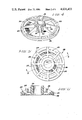
- FIG. 5 is an end view schematically illustrating a third embodiment of an end shield in accordance with the present invention.
- FIG. 6 is a side elevation, cross-sectional view of the end shield shown in FIG. 5, taken along line 6--6;
- FIG. 7 is a perspective view schematically illustrating a fourth embodiment of an end shield in accordance with the present invention.
- FIG. 8 is a side elevation, cross-sectional view of the end shield shown in FIG. 7, taken along line 8--8;
- FIG. 9 is a view similar to that of FIG. 5, schematically illustrating an end shield in accordance with a fifth embodiment of the present invention.
- FIG. 10 is a side elevation, cross-sectional view of the end shield shown in FIG. 9, taken along line 10--10;
- FIG. 11 is a side elevation, cross-sectional view schematically illustrating one embodiment of a means for attaching the end shield to the housing of a dynamoelectric machine, in accordance with the present invention.
- FIG. 12 is a view similar to that of FIG. 11 schematically illustrating an alternative embodiment for the attaching means shown in FIG. 11.
- FIG. 1 schematically illustrates one embodiment of an end shield for a dynamoelectric machine of the type having a rotor assembly rotatably disposed in a housing, in accordance with the present invention.
- the end shield comprises end plate 26, for attachment to the housing (not shown) so that end plate 26 provides structural support for one axial end of the rotor assembly (also not shown), and thermal barrier 28 located adjacent to end plate 26.
- End plate 26 is attached to the housing of the dynamoelectric machine so as to maintain a predetermined distance between the radially outermost portion of the rotor assembly and the radially innermost portion of the housing.
- Thermal barrier 28 is disposed so as to thermally insulate end plate 26 from heat generated inside the housing.
- the end shield of the present invention comprises two elements: a load-carrying portion that structurally supports an associated end of the rotor assembly and thereby maintains the rotor-stator air gap, and a thermally insulative portion which thermally insulates the load-carrying portion from heat generated inside the housing of the dynamoelectric machine.
- a thermal barrier 28 to thermally insulate end plate 26 in the manner provided by the present invention protects end plate 26 from the relatively high temperature caused by heat generated inside the machine housing, thereby avoiding the deterioration of the end plate's mechanical properties and the excessive creep that might otherwise occur when end plate 26 is formed from a plastic material.
- thermal barrier 28 comprises a plastic which has low thermal conductivity and which is capable of withstanding temperatures of approximately 150° C. to 200° C.
- Suitable materials for thermal barrier 28 include the class of plastics known as phenolics, and also the polyetherimide resin produced by General Electric Company under the designation of Ultem®.
- End plate 26 preferably comprises a high strength plastic, such as, for example, any of the General Electric Company materials known as Lexan® polycarbonate resin, Valox® thermoplastic resin, or Ultem® resin.
- the plastic material may be filled with a stiffening material, such as, for example, glass filaments.
- end plate 26 preferably comprises bearing boss 20 at least partially surrounded by mounting member 22, in the manner illustrated in FIG. 1.
- Bearing boss 20 is configured so as to receive a bearing assembly associated with the dynamoelectric machine's rotor assembly (not shown in the Figures).
- Mounting member 22 serves to attach end plate 26 to the machine housing (also not shown in the Figures).
- a plurality of radial support members 24 connects bearing boss 20 to mounting member 22. Radial support members 24 are disposed so as to support bearing boss 20 in position relative to mounting member 22.
- bearing boss 20 and mounting member 22 are each generally annularly shaped.
- Bearing boss 20 and mounting member 22 are further disposed so that the central axis of bearing boss 20 is substantially coaxially located with respect to the central axis of mounting member 22. Also, in the embodiment shown, each radial support member 24 extends between bearing boss 20 and mounting member 22 in a radial direction with respect to the central axis of bearing boss 20. In order to most economically produce end plate 26, and to provide it with maximum mechanical strength, bearing boss 20, mounting member 22, and radial support members 24 may be formed as a unitary structure.
- thermal barrier 28 also comprises an annularly shaped structure.
- FIG. 2 is a cross-sectional view taken along line 2--2 of the end shield of FIG. 1
- thermal barrier 28 in the embodiment shown in FIG. 1 is a relatively thin, substantially flat structure.
- thermal barrier 28 need not be flat in order to perform its function of thermally insulating end plate 26 from heat generated inside the machine housing.
- Thermal barrier 28 may also comprise other shapes, such as the annular structure shown in the alternative embodiment of the present invention shown in FIG. 3.
- thermal barrier 28 may extend radially throughout the radial distance between the innermost radius of bearing boss 20 and the outermost radius of mounting member 22, in the manner illustrated in FIG. 3, or for some lesser radial distance, in the manner illustrated in FIG. 2.
- each radial support member 24 is preferably further disposed so as to be spaced apart from thermal barrier 28, in the manner illustrated in FIGS. 2 and 3.
- bearing boss 20 may further include a plurality of reinforcing ribs 30 and 32 formed as an integral part of bearing boss 20.
- Axial reinforcing ribs 30 are located in a spaced-apart relationship around the outer circumference of bearing boss 20, with each axial reinforcing rib 30 extending in a direction which is parallel to the central axis of bearing boss 20.
- Circumferential reinforcing ribs 32 extend around the outer circumference of bearing boss 20, and are located in a spaced-apart relationship along the central axis of bearing boss 20.
- Axial reinforcing ribs 30 and circumferential reinforcing ribs 32 serve to provide bearing boss 20 with additional resistance to radial and axial distortion forces acting upon bearing boss 20. By employing reinforcing ribs 30 and 32 in this manner, the material used to form bearing boss 20 is more efficiently utilized.
- mounting member 22 may further include a plurality of reinforcing ribs 34 which extend in a circumferential direction with respect to the central axis of mounting member 22.
- Mounting member reinforcing ribs 34 are disposed so as to provide additional structural support between mounting member 22 and each of radial support members 24, thereby further facilitating efficient material utilization.
- FIG. 5 schematically illustrates an alternative embodiment of the present invention in which end plate 26 further includes a plurality of circumferential support members 36.
- Circumferential support members 36 extend in a circumferential direction with respect to the central axis of bearing boss 20, and are radially located with respect thereto between the outermost radius of bearing boss 20 and the innermost radius of mounting member 22.
- Each circumferential support member 36 is disposed so as to connect at least two of radial support members 20 to each other.
- FIG. 6 which is a cross-sectional view taken along line 6--6 of the end shield shown in FIG. 5
- circumferential support members 36 are preferably further disposed so as to be spaced apart from thermal barrier 28. With circumferential support members 36 and radial support members 24 spaced apart from thermal barrier 28 in the manner shown in FIG. 6, support members 24 and 36 are better protected from heat generated inside the machine housing.
- FIGS. 1-6 are especially useful for "non-ventilated" dynamoelectric machines, for which air flow through the end shield is not required.
- Non-ventilated end shields are employed in such applications as, for example, totally enclosed motors.
- the motor should be designed to efficiently remove heat generated inside the motor by conduction of the heat through the motor housing.
- thermal barrier 28 further includes means for directing heat generated inside the housing through thermal barrier 28 and away from end plate 26.
- this heat directing means comprises a plurality of vent openings 38 through thermal barrier 28. Vent openings 38 are arranged in a spaced-apart relationship about the central axis of thermal barrier 28, and are radially located with respect thereto between the outermost radius of bearing boss 20 and the innermost radius of mounting member 22. Vent openings 38 are also chimney shaped and disposed so that fluid flowing out of the machine housing (not shown in FIG. 7) through vent openings 38 is directed away from the structural components of end plate 26.
- ventilated end shields in accordance with the present invention may also include mounting member reinforcing ribs 34 and circumferential support members 36, in the same manner as illustrated in FIGS. 4-6 and described above in relation thereto.
- bearing boss 20 of a ventilated end shield in accordance with the present invention may include axial and circumferential reinforcing ribs, in the manner illustrated by reinforcing ribs 30 and 32 shown in FIG. 4 and described above in relation thereto.
- vent openings 38 are shown in cross-section in FIGS.
- the end shield of the present invention further comprises means for attaching the end plate and the thermal barrier to the machine housing.
- the attaching means comprises fastening screws 42, each disposed through associated screw opening 40, respectively, and extending through mounting member 22 and also through thermal barrier 28, into the motor housing (not shown).
- each fastening screw 42 is preferably thermally insulated from mounting member 22 by a respective thermally insulative material disposed between the adjacent surfaces of the respective fastening screw 42 and mounting member 22.
- this thermally insulative material comprises thermal barrier insert 46 which at least partially protrudes into screw opening 40, and insulative washer 48 disposed between mounting member 22 and the head of fastening screw 42.
- the thermally insulative material respectively disposed between the adjacent surfaces of each of fastening screws 42 and mounting member 22 comprises thermally insulative sleeve 50.
- a thermally insulative sleeve 50 is disposed, respectively, in each of screw openings 40 and each sleeve 50 protrudes from its respective screw opening 40 so as to thermally insulate all adjacent portions of the respective fastening screw 42 from mounting member 22.
- the foregoing describes an end shield for dynamoelectric machines, which end shield can be made from plastic materials while at the same time being capable of withstanding the relatively high temperatures caused by heat generated inside the machine housing of many conventional dynamoelectric machines.
- the present invention provides a means for thermally insulating the structural components of the end shield from this heat, thereby facilitating making the end shield from plastic materials which are low in weight and inexpensive to manufacture.
Landscapes
- Engineering & Computer Science (AREA)
- Power Engineering (AREA)
- Motor Or Generator Frames (AREA)
Abstract
A plastic end shield for use in a dynamoelectric machine of the type having a rotor assembly rotatably disposed in a housing includes an end plate for attachment to the housing, so as to provide structural support for one end of the rotor assembly, and a thermal barrier adjacent to the end plate for thermally insulating the end plate from heat generated inside the housing. In a preferred embodiment, radial and circumferential support members and axial and circumferential reinforcing ribs are employed in order to efficiently utilize the plastic material. The thermal barrier may be provided with a plurality of vent openings through which heat generated inside the housing can escape from the housing and the end plate. Means employed to attach the end plate and thermal barrier to the housing may include a thermally insulative material which prevents heat from being conducted from the housing to the end plate.
Description
This invention relates to dynamoelectric machines. More particularly, it relates to plastic end shields for use in such dynamoelectric machines as motors, generators, and the like.
Conventional dynamoelectric machines typically include a housing, a rotor assembly rotatably disposed in the housing, and one or more end shields which provide structural support for associated axial ends of the rotor assembly. The end shields are usually made of steel, aluminum, cast iron, or other die cast alloy. Plastic end shields have also been used in the past, but only for very small motors. Plastic end shields have typically been employed in motors for such applications as toys and small appliances, where very little heat is generated inside the motor housing. For such applications, employing plastic end shields as a substitute for metal end shields has required little more than using a plastic material in the same mold that would be used to make a metal end shield for the same application.
However, for more demanding applications, such as, for example, motors of horsepower ratings above 0.05 horsepower, a significant amount of heat is generated inside the motor housing, and the end shields for the motor are subjected to temperatures as high as 200° C. While such temperatures do not present any significant problems when metal end shields are employed, such elevated temperatures in plastic end shields may cause deterioration of the mechanical properties of the plastic material, and excessive creep in the plastic structure. Most of the relatively inexpensive plastic materials currently available exhibit durable mechanical properties at relatively low temperatures. At higher temperatures, however, the mechanical properties of the material deteriorate significantly. As a result, end shields made of such materials may fail in their primary function of maintaining the proper distance between the outermost radius of the rotor assembly and the innermost radius of the housing, which distance is often referred to as the rotor-stator air gap. Plastic materials capable of withstanding higher temperatures are available, but such materials are relatively expensive and generally do not offer any cost savings over metal end shields. Thus, while end shields made from inexpensive plastic materials would be much lighter than the metal end shields currently employed, and would offer the potential for reducing manufacturing costs, it is not feasible to directly substitute such plastic materials in the metal end shield designs currently employed for dynamoelectric machines which generate a significant amount of heat inside the housing.
Furthermore, the primary motivation for replacing metal end shields with plastic end shields is not the cost of the material itself (which, in many applications, is greater for plastics than for metals), but rather a reduction in the overall manufacturing cost of the end shield. Because relatively complex parts can be molded from plastics, a metal assembly involving several different components can often be replaced by a single plastic part, at a lower overall manufacturing cost. Thus, an effective exploitation of the advantages provided by using plastics to form an end shield requires a design in which multi-functionality can be incorporated into the end shield. In dynamoelectric machines, besides serving to maintain the rotor-stator air gap, the end shields also often perform such functions as providing an oil reservoir or grease cavity around the bearings, serving as a mounting bracket, or providing a mount for such accessories as tachometers, brakes, blowers, switches, or brush rings. Plastic end shields can be designed to combine several of these functions. For example, since plastic is an electrically insulative material, the brush support ring used in D.C. machines can be formed as an integral part of the end shield. By providing multi-functionality in this manner, plastic end shields can offer significant reductions in overall manufacturing costs.
Accordingly, it is an object of the present invention to provide an end shield for dynamoelectric machines which is light in weight and inexpensive to manufacture.
It is also an object of the present invention to provide an end shield capable of withstanding relatively high temperatures caused by heat generated inside the machine housing.
It is a further object of the present invention to provide an end shield which is made from plastic.
A plastic end shield for a dynamoelectric machine of the type having a rotor assembly rotatably disposed in a housing comprises an end plate for attachment to the housing so that the end plate provides structural support for one end of the rotor assembly, and a thermal barrier located adjacent to the end plate and disposed so as to thermally insulate the end plate from heat generated inside the housing. In a preferred embodiment, the end shield comprises a bearing boss, for receiving a bearing assembly associated with the rotor assembly, and a mounting member at least partially surrounding the bearing boss, for attaching the end plate to the housing. A plurality of radial support members connects the bearing boss to the mounting member. The end plate may also include circumferential support members which connect the radial support members to each other. The thermal barrier preferably comprises a plastic which is capable of withstanding relatively high temperatures, and may further include a plurality of vent openings through which the heat generated inside the housing is directed out of the housing and away from the end plate. Means for attaching the end plate and the thermal barrier to the housing preferably includes a thermally insulative material which prevents heat from being conducted from the housing to the end plate.
The subject matter which is regarded as the invention is particularly pointed out and distinctly claimed in the concluding portion of the specification. The invention itself, however, both as to its organization and its method of practice, together with further objects and advantages thereof, may best be understood by reference to the following description taken in conjunction with the accompanying drawings, in which:
FIG. 1 is a perspective view schematically illustrating one embodiment of an end shield for a dynamoelectric machine, in accordance with the present invention;
FIG. 2 is a side elevation, cross-sectional view of the end shield shown in FIG. 1, taken along line 2--2;
FIG. 3 is a similar view to that of FIG. 2, schematically illustrating an alternative embodiment to that shown in FIG. 2;
FIG. 4 is a perspective view schematically illustrating a second embodiment of an end shield for a dynamoelectric machine, in accordance with the present invention;
FIG. 5 is an end view schematically illustrating a third embodiment of an end shield in accordance with the present invention;
FIG. 6 is a side elevation, cross-sectional view of the end shield shown in FIG. 5, taken along line 6--6;
FIG. 7 is a perspective view schematically illustrating a fourth embodiment of an end shield in accordance with the present invention;
FIG. 8 is a side elevation, cross-sectional view of the end shield shown in FIG. 7, taken along line 8--8;
FIG. 9 is a view similar to that of FIG. 5, schematically illustrating an end shield in accordance with a fifth embodiment of the present invention;
FIG. 10 is a side elevation, cross-sectional view of the end shield shown in FIG. 9, taken along line 10--10;
FIG. 11 is a side elevation, cross-sectional view schematically illustrating one embodiment of a means for attaching the end shield to the housing of a dynamoelectric machine, in accordance with the present invention; and
FIG. 12 is a view similar to that of FIG. 11 schematically illustrating an alternative embodiment for the attaching means shown in FIG. 11.
FIG. 1 schematically illustrates one embodiment of an end shield for a dynamoelectric machine of the type having a rotor assembly rotatably disposed in a housing, in accordance with the present invention. The end shield comprises end plate 26, for attachment to the housing (not shown) so that end plate 26 provides structural support for one axial end of the rotor assembly (also not shown), and thermal barrier 28 located adjacent to end plate 26. End plate 26 is attached to the housing of the dynamoelectric machine so as to maintain a predetermined distance between the radially outermost portion of the rotor assembly and the radially innermost portion of the housing. Thermal barrier 28 is disposed so as to thermally insulate end plate 26 from heat generated inside the housing. Thus, the end shield of the present invention comprises two elements: a load-carrying portion that structurally supports an associated end of the rotor assembly and thereby maintains the rotor-stator air gap, and a thermally insulative portion which thermally insulates the load-carrying portion from heat generated inside the housing of the dynamoelectric machine. Employing thermal barrier 28 to thermally insulate end plate 26 in the manner provided by the present invention protects end plate 26 from the relatively high temperature caused by heat generated inside the machine housing, thereby avoiding the deterioration of the end plate's mechanical properties and the excessive creep that might otherwise occur when end plate 26 is formed from a plastic material. In a preferred embodiment, thermal barrier 28 comprises a plastic which has low thermal conductivity and which is capable of withstanding temperatures of approximately 150° C. to 200° C. Suitable materials for thermal barrier 28 include the class of plastics known as phenolics, and also the polyetherimide resin produced by General Electric Company under the designation of Ultem®. End plate 26 preferably comprises a high strength plastic, such as, for example, any of the General Electric Company materials known as Lexan® polycarbonate resin, Valox® thermoplastic resin, or Ultem® resin. To provide end plate 26 with additional stiffness, the plastic material may be filled with a stiffening material, such as, for example, glass filaments.
For typical conventional dynamoelectric machines, in which the housing surrounds the rotor assembly, end plate 26 preferably comprises bearing boss 20 at least partially surrounded by mounting member 22, in the manner illustrated in FIG. 1. Bearing boss 20 is configured so as to receive a bearing assembly associated with the dynamoelectric machine's rotor assembly (not shown in the Figures). Mounting member 22 serves to attach end plate 26 to the machine housing (also not shown in the Figures). A plurality of radial support members 24 connects bearing boss 20 to mounting member 22. Radial support members 24 are disposed so as to support bearing boss 20 in position relative to mounting member 22. In the embodiment shown in FIG. 1, bearing boss 20 and mounting member 22 are each generally annularly shaped. Bearing boss 20 and mounting member 22 are further disposed so that the central axis of bearing boss 20 is substantially coaxially located with respect to the central axis of mounting member 22. Also, in the embodiment shown, each radial support member 24 extends between bearing boss 20 and mounting member 22 in a radial direction with respect to the central axis of bearing boss 20. In order to most economically produce end plate 26, and to provide it with maximum mechanical strength, bearing boss 20, mounting member 22, and radial support members 24 may be formed as a unitary structure.
In the embodiment shown in FIG. 1, thermal barrier 28 also comprises an annularly shaped structure. As is better illustrated in FIG. 2, which is a cross-sectional view taken along line 2--2 of the end shield of FIG. 1, thermal barrier 28 in the embodiment shown in FIG. 1 is a relatively thin, substantially flat structure. However, thermal barrier 28 need not be flat in order to perform its function of thermally insulating end plate 26 from heat generated inside the machine housing. Thermal barrier 28 may also comprise other shapes, such as the annular structure shown in the alternative embodiment of the present invention shown in FIG. 3. Furthermore, thermal barrier 28 may extend radially throughout the radial distance between the innermost radius of bearing boss 20 and the outermost radius of mounting member 22, in the manner illustrated in FIG. 3, or for some lesser radial distance, in the manner illustrated in FIG. 2. The actual radial extent of thermal barrier 28 for a particular application depends upon the amount of thermal insulation required to be provided by thermal barrier 28 for that application. Also, in order to further protect radial support members 24 from heat generated inside the machine housing, each radial support member 24 is preferably further disposed so as to be spaced apart from thermal barrier 28, in the manner illustrated in FIGS. 2 and 3.
As is schematically illustrated by the embodiment of the present invention shown in FIG. 4, bearing boss 20 may further include a plurality of reinforcing ribs 30 and 32 formed as an integral part of bearing boss 20. Axial reinforcing ribs 30 are located in a spaced-apart relationship around the outer circumference of bearing boss 20, with each axial reinforcing rib 30 extending in a direction which is parallel to the central axis of bearing boss 20. Circumferential reinforcing ribs 32 extend around the outer circumference of bearing boss 20, and are located in a spaced-apart relationship along the central axis of bearing boss 20. Axial reinforcing ribs 30 and circumferential reinforcing ribs 32 serve to provide bearing boss 20 with additional resistance to radial and axial distortion forces acting upon bearing boss 20. By employing reinforcing ribs 30 and 32 in this manner, the material used to form bearing boss 20 is more efficiently utilized. As is also illustrated in FIG. 4, mounting member 22 may further include a plurality of reinforcing ribs 34 which extend in a circumferential direction with respect to the central axis of mounting member 22. Mounting member reinforcing ribs 34 are disposed so as to provide additional structural support between mounting member 22 and each of radial support members 24, thereby further facilitating efficient material utilization. By distributing the plastic material in the manner illustrated, so as to move material from regions of low stress to regions of high stress, the amount of plastic material required to achieve a given level of mechanical strength for the end shield can be reduced.
FIG. 5 schematically illustrates an alternative embodiment of the present invention in which end plate 26 further includes a plurality of circumferential support members 36. Circumferential support members 36 extend in a circumferential direction with respect to the central axis of bearing boss 20, and are radially located with respect thereto between the outermost radius of bearing boss 20 and the innermost radius of mounting member 22. Each circumferential support member 36 is disposed so as to connect at least two of radial support members 20 to each other. As is illustrated in FIG. 6, which is a cross-sectional view taken along line 6--6 of the end shield shown in FIG. 5, circumferential support members 36 are preferably further disposed so as to be spaced apart from thermal barrier 28. With circumferential support members 36 and radial support members 24 spaced apart from thermal barrier 28 in the manner shown in FIG. 6, support members 24 and 36 are better protected from heat generated inside the machine housing.
The embodiments of the present invention illustrated in FIGS. 1-6 are especially useful for "non-ventilated" dynamoelectric machines, for which air flow through the end shield is not required. Non-ventilated end shields are employed in such applications as, for example, totally enclosed motors. When non-ventilated plastic end shields are employed in these applications, the motor should be designed to efficiently remove heat generated inside the motor by conduction of the heat through the motor housing.
For applications requiring air flow through the end shield, the embodiments of the present invention illustrated in FIGS. 7-10 are preferred. For such applications, thermal barrier 28 further includes means for directing heat generated inside the housing through thermal barrier 28 and away from end plate 26. In the embodiment illustrated in FIG. 7, this heat directing means comprises a plurality of vent openings 38 through thermal barrier 28. Vent openings 38 are arranged in a spaced-apart relationship about the central axis of thermal barrier 28, and are radially located with respect thereto between the outermost radius of bearing boss 20 and the innermost radius of mounting member 22. Vent openings 38 are also chimney shaped and disposed so that fluid flowing out of the machine housing (not shown in FIG. 7) through vent openings 38 is directed away from the structural components of end plate 26.
As is illustrated in FIGS. 9 and 10, ventilated end shields in accordance with the present invention may also include mounting member reinforcing ribs 34 and circumferential support members 36, in the same manner as illustrated in FIGS. 4-6 and described above in relation thereto. Similarly, although not shown in FIGS. 7-10, bearing boss 20 of a ventilated end shield in accordance with the present invention may include axial and circumferential reinforcing ribs, in the manner illustrated by reinforcing ribs 30 and 32 shown in FIG. 4 and described above in relation thereto. Additionally, while vent openings 38 are shown in cross-section in FIGS. 8 and 10 as being in the form of spouts or ducts, other shapes which perform the same function of carrying hot air out of the machine housing and directing it away from the structural components of the end shield may also be utilized. For vent opening shapes which accomplish this function, the load-bearing portions of the plastic end shield are not exposed to the hot air exiting from the interior of the machine housing, and are thereby protected from deterioration caused by such heat.
The end shield of the present invention further comprises means for attaching the end plate and the thermal barrier to the machine housing. In the embodiment schematically illustrated in FIG. 11, the attaching means comprises fastening screws 42, each disposed through associated screw opening 40, respectively, and extending through mounting member 22 and also through thermal barrier 28, into the motor housing (not shown). In order to prevent conduction of heat by fastening screws 42 from housing 44 to mounting member 22, each fastening screw 42 is preferably thermally insulated from mounting member 22 by a respective thermally insulative material disposed between the adjacent surfaces of the respective fastening screw 42 and mounting member 22. In the embodiment shown in FIG. 11, this thermally insulative material comprises thermal barrier insert 46 which at least partially protrudes into screw opening 40, and insulative washer 48 disposed between mounting member 22 and the head of fastening screw 42. In an alternative embodiment to that shown in FIG. 11, which is schematically illustrated in FIG. 12, the thermally insulative material respectively disposed between the adjacent surfaces of each of fastening screws 42 and mounting member 22 comprises thermally insulative sleeve 50. A thermally insulative sleeve 50 is disposed, respectively, in each of screw openings 40 and each sleeve 50 protrudes from its respective screw opening 40 so as to thermally insulate all adjacent portions of the respective fastening screw 42 from mounting member 22. By thermally insulating each fastening screw 42 from mounting member 22 in the manner illustrated in FIGS. 11 and 12, heating of mounting member 22, which heating might cause elevated temperatures and associated creep in the plastic material surrounding each of screw openings 40, is reduced.
The foregoing describes an end shield for dynamoelectric machines, which end shield can be made from plastic materials while at the same time being capable of withstanding the relatively high temperatures caused by heat generated inside the machine housing of many conventional dynamoelectric machines. The present invention provides a means for thermally insulating the structural components of the end shield from this heat, thereby facilitating making the end shield from plastic materials which are low in weight and inexpensive to manufacture.
While the invention has been described in detail herein in accord with certain preferred embodiments thereof, many modifications and changes therein may be effected by those skilled in the art. Accordingly, it is intended by the appended claims to cover all such modifications and changes as fall within the true spirit and scope of the invention.
Claims (20)
1. An end shield for a dynamoelectric machine of the type having a rotor assembly rotatably disposed in a housing, said end shield comprising:
an end plate comprising high strength plastic attached to said housing for providing structural support for one axial end of said rotor assembly and for maintaining a predetermined distance between the radially outermost portion of said rotor assembly and the radially innermost portion of said housing; and
a substantially solid thermal barrier comprising a plastic plate having both a low thermal conductivity and an ability to withstand heat in the range of approximately 150-200 degrees centigrade located adjacent to said end plate and disposed so as to thermally insulate said end plate from connective heat generated inside said housing.
2. The end shield of claim 1 wherein said thermal barrier further includes means for directing (therethrough) heat generated inside of said housing out of said housing and away from said end plate.
3. The end shield of claim 1 further comprising means for attaching said end plate and said thermal barrier to said housing.
4. The end shield of claim 1 wherein said end plate comprises:
a bearing boss, for receiving a bearing assembly associated with said rotor assembly;
a mounting member at least partially surrounding said bearing boss, for attaching said end plate to said housing; and
a plurality of radial support members connecting said bearing boss to said mounting member, with said radial support members being disposed so as to support said bearing boss in position relative to said mounting member.
5. The end shield of claim 4 wherein each said radial support member is further disposed so as to be spaced apart from said thermal barrier.
6. The end of shield claim 4 wherein said bearing boss, said mounting member, and said radial support members comprise a unitary structure.
7. The end shield of claim 6 wherein said bearing boss and said mounting member are each generally annularly shaped and are disposed so that the central axis of said bearing boss is substantially coaxially located with respect to the central axis of said mounting member, and wherein each said radial support member extends between said bearing boss and said mounting member in a radial direction with respect to said central axis of said bearing boss.
8. The end shield of claim 7 wherein said end plate further includes a plurality of circumferential support members extending in a circumferential direction with respect to said central axis of said bearing boss, said circumferential support members being radially located between the outermost radius of said bearing boss and the innermost radius of said mounting member, with each said circumferential support member being disposed so as to connect at least two of said radial support members to each other.
9. The end shield of claim 8 wherein each said circumferential support member is further disposed so as to be spaced apart from said thermal barrier.
10. The end shield of claim 7 wherein said bearing boss includes a plurality of reinforcing ribs formed as an integral part of said bearing boss, with said reinforcing ribs being disposed around the outer circumference of said bearing boss so as to provide said bearing boss with additional resistance to radial and axial distortion forces acting on said bearing boss.
11. The end shield of claim 7 wherein said mounting member includes a plurality of reinforcing ribs disposed so as to provide additonal structural support between said mounting member and said plurality of radial support members.
12. The end shield of claim 7 wherein said thermal barrier comprises a generally annularly shaped structure disposed so that the central axis thereof is substantially coaxially located with respect to the central axis of said bearing boss.
13. The end shield of claim 12 wherein said thermal barrier extends radially between the innermost radius of said bearing boss and the outermost radius of said mounting member.
14. the end shield of claim 12 wherein said thermal barrier comprises a substantially flat structure.
15. The end shield of claim 2 wherein said heat directing means includes a plurality of chimney shaped vent openings through said thermal barrier and disposed so that fluid flowing out of said housing through said vent openings is directed away from said end plate.
16. The end shield of claim 15 wherein said vent openings are further arranged in a spaced-apart relationship about the central axis of said thermal barrier.
17. The end shield of claim 3 wherein said attaching means comprises a plurality of fastening screws, each of said screws extending through an associated screw opening, respectively, in said thermal barrier and also through an associated screw opening, respectively, in said end plate, each of said fastening screws being thermally insulated from said end plate by thermally insulative material situated between the adjacent surfaces of each of said screws and said end plate.
18. The end shield of claim 17 wherein said thermally insulative material between each of said screws and said end plate comprises a thermally insulative sleeve disposed, respectively, in each of said screw openings, respectively, in said end plate.
19. The end shield of claim 4 wherein said thermal barrier comprises a substantially solid plate extending between said bearing boss and said mounting member.
20. The end shield of claim 19 wherein said thermal barrier comprises a phenolic or ULTEM polyetherimide resin.
Priority Applications (1)
| Application Number | Priority Date | Filing Date | Title |
|---|---|---|---|
| US06/730,889 US4631433A (en) | 1985-05-06 | 1985-05-06 | Plastic end shield with thermal barrier for dynamoelectric machines |
Applications Claiming Priority (1)
| Application Number | Priority Date | Filing Date | Title |
|---|---|---|---|
| US06/730,889 US4631433A (en) | 1985-05-06 | 1985-05-06 | Plastic end shield with thermal barrier for dynamoelectric machines |
Publications (1)
| Publication Number | Publication Date |
|---|---|
| US4631433A true US4631433A (en) | 1986-12-23 |
Family
ID=24937204
Family Applications (1)
| Application Number | Title | Priority Date | Filing Date |
|---|---|---|---|
| US06/730,889 Expired - Fee Related US4631433A (en) | 1985-05-06 | 1985-05-06 | Plastic end shield with thermal barrier for dynamoelectric machines |
Country Status (1)
| Country | Link |
|---|---|
| US (1) | US4631433A (en) |
Cited By (59)
| Publication number | Priority date | Publication date | Assignee | Title |
|---|---|---|---|---|
| US4980592A (en) * | 1989-09-01 | 1990-12-25 | Textron, Inc. | Flywheel magnet rotor assembly |
| US5065489A (en) * | 1988-07-28 | 1991-11-19 | Eastman Kodak Company | Apparatus for aligning and mounting machine components |
| EP0589187A1 (en) * | 1992-09-24 | 1994-03-30 | Licentia Patent-Verwaltungs-GmbH | Totally enclosed liquid-cooled, fully enclosed electrical engine |
| US5378102A (en) * | 1991-09-30 | 1995-01-03 | Sfs Stadler, Inc. | Barrel assembly and composite stress plate |
| EP0667670A1 (en) * | 1994-02-10 | 1995-08-16 | Emerson Electric Co. | Motor assemblies with improved endshields |
| GB2303743A (en) * | 1995-07-22 | 1997-02-26 | Aisin Seiki | Damping vibration in a switched reluctance motor |
| US5783881A (en) * | 1995-10-21 | 1998-07-21 | Emb Elektrobau Mulfingen Gmbh & Co. | Brushless electric motor with heat sink and mounting arrangement thereof |
| US5818142A (en) * | 1995-07-27 | 1998-10-06 | Black & Decker Inc. | Motor pack armature support with brush holder assembly |
| US5905320A (en) * | 1997-10-08 | 1999-05-18 | Siemens Canada Limited | Housing for an ultra quiet electric motor |
| US5914550A (en) * | 1997-10-08 | 1999-06-22 | Siemens Canada Limited | Mounting flange for an ultra quiet electric motor |
| US5917258A (en) * | 1997-10-08 | 1999-06-29 | Siemens Canada Limited | Bearing assembly for an ultra quiet electric motor |
| US5945756A (en) * | 1997-10-07 | 1999-08-31 | Siemens Canada Limited | Ultra quiet electric motor for automotive applications |
| US5949163A (en) * | 1998-10-26 | 1999-09-07 | General Electric Company | Reinforced motor having reduced operational vibration amplitude |
| US5969447A (en) * | 1997-10-08 | 1999-10-19 | Simens Canada Limited | End cap for an ultra quiet electric motor |
| US6093990A (en) * | 1999-10-05 | 2000-07-25 | Meeks; David S. | Covering device for totally enclosed fan cooled motors |
| US6125528A (en) * | 1997-04-24 | 2000-10-03 | Electric Boat Corporation | Method for making a composite electric motor housing |
| US6211587B1 (en) * | 1998-11-12 | 2001-04-03 | Hitachi, Ltd. | Electric rotating machine |
| US6274957B1 (en) | 1998-09-04 | 2001-08-14 | Emerson Electric Co. | Reduced size electromagnetic device |
| US20020130570A1 (en) * | 2001-03-16 | 2002-09-19 | Howe Steven S. | Alternator and method of manufacture |
| US20030062800A1 (en) * | 2000-10-12 | 2003-04-03 | Kenji Nagai | Starter motor for internal combustion engines |
| US20040040243A1 (en) * | 2002-09-04 | 2004-03-04 | Pinconning Metals, Inc. | Attachment plate |
| US6906440B1 (en) * | 2000-06-13 | 2005-06-14 | General Electric Canada, Inc. | Bracket assembly having a plurality of plates for a dynamoelectric machine |
| US20050135953A1 (en) * | 2003-12-19 | 2005-06-23 | Annovi Reverberi S.P.A. | Hydraulic pump |
| US6949849B1 (en) | 1998-06-30 | 2005-09-27 | General Electric Company | Motor endshield assembly for an electronically commutated motor |
| US20060024173A1 (en) * | 2004-08-02 | 2006-02-02 | Annovi Reverberi S.P.A. | Pump body with plunger pistons |
| WO2007110303A1 (en) * | 2006-03-24 | 2007-10-04 | Appliances Components Companies S.P.A. | Improvement in an electric motor |
| US20080016983A1 (en) * | 2004-07-28 | 2008-01-24 | Dietmar Saur | Intermediate Flange for a Machine Tool |
| US20080197731A1 (en) * | 2007-02-15 | 2008-08-21 | Nidec Corporation | Brushless motor and pump mounted with brushless motor |
| US20080290749A1 (en) * | 2006-01-05 | 2008-11-27 | Abb Oy | End Shield |
| US20090173028A1 (en) * | 2008-01-09 | 2009-07-09 | Talan Products, Inc. | Roofing Membrane Retainer |
| DE102008046187A1 (en) * | 2008-09-06 | 2010-03-11 | Schaeffler Kg | Rotor i.e. external rotor, for washing machine-direct drive, has reinforcing structure comprising segment-like surface sections, which are alternately arranged and comprise axial distance increasing in radial direction |
| US20100326006A1 (en) * | 2009-06-26 | 2010-12-30 | Richard Yaros | Attachment plate |
| USD636503S1 (en) | 2008-01-09 | 2011-04-19 | Talan Products, Inc. | Roofing membrane seam plate |
| US20110088245A1 (en) * | 2008-07-22 | 2011-04-21 | The Boeing Company | Insulating cover for fasteners used in high temperature environments |
| US20110260467A1 (en) * | 2008-10-08 | 2011-10-27 | Aloys Wobben | Ring generator |
| US20130076167A1 (en) * | 2011-09-23 | 2013-03-28 | Remy Technologies, Llc | Cooling system and method for electronic machines |
| US20130091902A1 (en) * | 2010-06-25 | 2013-04-18 | Fisher & Paykel Appliances Limited | Rotor for a motor, and a motor and an appliance comprising the rotor, and a method for making a rotor |
| US20130193687A1 (en) * | 2010-09-13 | 2013-08-01 | Jing-Jin Electric Techologies (Beijing) Co., Ltd. | Rotor Device Of Integrated Stater-Generator Motor And Rotor Working System |
| US8502436B2 (en) | 2011-02-14 | 2013-08-06 | Regal Beloit America, Inc. | Electric motor having an end frame |
| US20140230566A1 (en) * | 2011-09-27 | 2014-08-21 | Endress + Hauser Flowtec Ag | Bolt Sleeve |
| US20150091396A1 (en) * | 2013-09-30 | 2015-04-02 | Nidec Motor Corporation | End Shield With Extrusions For Mounting The End Shield To A Stator Stack |
| US20160146233A1 (en) * | 2014-11-21 | 2016-05-26 | Robert Bosch Gmbh | Electrical machine comprising a fastening flange |
| AU2015202559B2 (en) * | 2010-06-25 | 2016-06-16 | Fisher & Paykel Appliances Limited | A rotor for a motor, and a motor and an appliance comprising the rotor, and a method for making a rotor |
| US9438079B2 (en) | 2012-05-23 | 2016-09-06 | Black & Decker Inc. | Armature end insulator for a power tool motor |
| US20160263683A1 (en) * | 2015-03-12 | 2016-09-15 | Robert Bosch Tool Corporation | Power Tool with Drop Arm Orbit Bracket |
| US20160263679A1 (en) * | 2015-03-12 | 2016-09-15 | Robert Bosch Tool Corporation | Power Tool Motor with Reduced Electrical Noise |
| US9447810B2 (en) | 2008-07-22 | 2016-09-20 | The Boeing Company | Insulating washers |
| US20160273536A1 (en) * | 2013-10-25 | 2016-09-22 | Valeo Japan Co., Ltd. | Electric scroll compressor |
| FR3065592A1 (en) * | 2017-04-20 | 2018-10-26 | Valeo Equipements Electriques Moteur | ROTATING ELECTRIC MACHINE HAVING A CONFIGURATION BEARING ENHANCING COOLING |
| WO2019236652A1 (en) * | 2018-06-05 | 2019-12-12 | Viza Electronics Pte. Ltd. | Surge protection module and related components and methods |
| DE102019129024A1 (en) | 2018-10-29 | 2020-04-30 | Nidec Corporation | Motor and reduction gear |
| US20200204032A1 (en) * | 2018-12-21 | 2020-06-25 | Abb Schweiz Ag | Polymeric industrial electrical machine |
| US10767684B1 (en) * | 2019-04-26 | 2020-09-08 | Solsera, Inc. | Flat roof mounting device |
| US10781587B2 (en) | 2016-12-14 | 2020-09-22 | Solsera, Inc. | Structural attachment sealing system |
| DE102020111416A1 (en) | 2020-04-27 | 2021-10-28 | Bayerische Motoren Werke Aktiengesellschaft | Rotor as well as electrical machine |
| USD943405S1 (en) | 2020-02-10 | 2022-02-15 | Talan Products, Inc. | Roofing membrane seam plate |
| US20220099136A1 (en) * | 2019-04-26 | 2022-03-31 | Solsera, Inc. | Flat Roof Mounting Device |
| US11502588B2 (en) * | 2018-12-21 | 2022-11-15 | Abb Schweiz Ag | Manufacture of a polymeric electrical machine |
| US11962137B2 (en) | 2020-04-21 | 2024-04-16 | Unirac Inc. | Electric junction box mount apparatus |
Citations (10)
| Publication number | Priority date | Publication date | Assignee | Title |
|---|---|---|---|---|
| US2810084A (en) * | 1955-07-18 | 1957-10-15 | Iron Fireman Mfg Co | Motor and end bell therefor |
| US3255559A (en) * | 1962-02-21 | 1966-06-14 | Basf Ag | Elements for securing protective screens to articles to be protected from the action of heat and flames |
| US3490820A (en) * | 1967-11-06 | 1970-01-20 | Emerson Electric Co | Capacitor clamp for electric motor |
| US3527971A (en) * | 1968-05-08 | 1970-09-08 | Applied Motors Inc | Apparatus for mounting brushes and diodes in a dynamoelectric machine |
| US3760209A (en) * | 1972-05-25 | 1973-09-18 | Vernco Corp | Split end bell for motor housing |
| US4098754A (en) * | 1974-12-19 | 1978-07-04 | Bayer Aktiengesellschaft | Process for the preparation of high molecular thermoplastic polycarbonates of low flammability |
| US4355253A (en) * | 1981-02-27 | 1982-10-19 | Briggs & Stratton Corp. | Combination end bell and brush holder for a dynamoelectric machine |
| US4384224A (en) * | 1979-05-11 | 1983-05-17 | Koehring Company | Drive unit for flexshaft vibrators |
| US4530952A (en) * | 1982-12-29 | 1985-07-23 | Mitsubishi Petrochemical Co., Ltd. | Polyphenylene ether composition improved in processability |
| US4549242A (en) * | 1981-06-05 | 1985-10-22 | Merlin Gerin | Molded case circuit breaker with cooling and protection for the static tripping unit |
-
1985
- 1985-05-06 US US06/730,889 patent/US4631433A/en not_active Expired - Fee Related
Patent Citations (10)
| Publication number | Priority date | Publication date | Assignee | Title |
|---|---|---|---|---|
| US2810084A (en) * | 1955-07-18 | 1957-10-15 | Iron Fireman Mfg Co | Motor and end bell therefor |
| US3255559A (en) * | 1962-02-21 | 1966-06-14 | Basf Ag | Elements for securing protective screens to articles to be protected from the action of heat and flames |
| US3490820A (en) * | 1967-11-06 | 1970-01-20 | Emerson Electric Co | Capacitor clamp for electric motor |
| US3527971A (en) * | 1968-05-08 | 1970-09-08 | Applied Motors Inc | Apparatus for mounting brushes and diodes in a dynamoelectric machine |
| US3760209A (en) * | 1972-05-25 | 1973-09-18 | Vernco Corp | Split end bell for motor housing |
| US4098754A (en) * | 1974-12-19 | 1978-07-04 | Bayer Aktiengesellschaft | Process for the preparation of high molecular thermoplastic polycarbonates of low flammability |
| US4384224A (en) * | 1979-05-11 | 1983-05-17 | Koehring Company | Drive unit for flexshaft vibrators |
| US4355253A (en) * | 1981-02-27 | 1982-10-19 | Briggs & Stratton Corp. | Combination end bell and brush holder for a dynamoelectric machine |
| US4549242A (en) * | 1981-06-05 | 1985-10-22 | Merlin Gerin | Molded case circuit breaker with cooling and protection for the static tripping unit |
| US4530952A (en) * | 1982-12-29 | 1985-07-23 | Mitsubishi Petrochemical Co., Ltd. | Polyphenylene ether composition improved in processability |
Cited By (101)
| Publication number | Priority date | Publication date | Assignee | Title |
|---|---|---|---|---|
| US5065489A (en) * | 1988-07-28 | 1991-11-19 | Eastman Kodak Company | Apparatus for aligning and mounting machine components |
| US4980592A (en) * | 1989-09-01 | 1990-12-25 | Textron, Inc. | Flywheel magnet rotor assembly |
| US5378102A (en) * | 1991-09-30 | 1995-01-03 | Sfs Stadler, Inc. | Barrel assembly and composite stress plate |
| EP0589187A1 (en) * | 1992-09-24 | 1994-03-30 | Licentia Patent-Verwaltungs-GmbH | Totally enclosed liquid-cooled, fully enclosed electrical engine |
| EP0667670A1 (en) * | 1994-02-10 | 1995-08-16 | Emerson Electric Co. | Motor assemblies with improved endshields |
| GB2303743B (en) * | 1995-07-22 | 1999-12-22 | Aisin Seiki | Switched reluctance motor |
| GB2303743A (en) * | 1995-07-22 | 1997-02-26 | Aisin Seiki | Damping vibration in a switched reluctance motor |
| US5818142A (en) * | 1995-07-27 | 1998-10-06 | Black & Decker Inc. | Motor pack armature support with brush holder assembly |
| US5783881A (en) * | 1995-10-21 | 1998-07-21 | Emb Elektrobau Mulfingen Gmbh & Co. | Brushless electric motor with heat sink and mounting arrangement thereof |
| US6150743A (en) * | 1997-04-24 | 2000-11-21 | Electric Boat Corporation | Composite motor end housing with a metallic sleeve bearing support |
| US6125528A (en) * | 1997-04-24 | 2000-10-03 | Electric Boat Corporation | Method for making a composite electric motor housing |
| US5945756A (en) * | 1997-10-07 | 1999-08-31 | Siemens Canada Limited | Ultra quiet electric motor for automotive applications |
| US5969447A (en) * | 1997-10-08 | 1999-10-19 | Simens Canada Limited | End cap for an ultra quiet electric motor |
| US5917258A (en) * | 1997-10-08 | 1999-06-29 | Siemens Canada Limited | Bearing assembly for an ultra quiet electric motor |
| US5914550A (en) * | 1997-10-08 | 1999-06-22 | Siemens Canada Limited | Mounting flange for an ultra quiet electric motor |
| US5905320A (en) * | 1997-10-08 | 1999-05-18 | Siemens Canada Limited | Housing for an ultra quiet electric motor |
| US6949849B1 (en) | 1998-06-30 | 2005-09-27 | General Electric Company | Motor endshield assembly for an electronically commutated motor |
| US6274957B1 (en) | 1998-09-04 | 2001-08-14 | Emerson Electric Co. | Reduced size electromagnetic device |
| US6407474B1 (en) | 1998-09-04 | 2002-06-18 | Emerson Electric Co. | Reduced size electromagnetic device with a stator winding spacer and an insulator |
| US5949163A (en) * | 1998-10-26 | 1999-09-07 | General Electric Company | Reinforced motor having reduced operational vibration amplitude |
| US6211587B1 (en) * | 1998-11-12 | 2001-04-03 | Hitachi, Ltd. | Electric rotating machine |
| US6093990A (en) * | 1999-10-05 | 2000-07-25 | Meeks; David S. | Covering device for totally enclosed fan cooled motors |
| US6906440B1 (en) * | 2000-06-13 | 2005-06-14 | General Electric Canada, Inc. | Bracket assembly having a plurality of plates for a dynamoelectric machine |
| US20030062800A1 (en) * | 2000-10-12 | 2003-04-03 | Kenji Nagai | Starter motor for internal combustion engines |
| US20050121988A1 (en) * | 2001-03-16 | 2005-06-09 | Altech Generating Systems Llc | Alternator and method of manufacture |
| US20040169429A1 (en) * | 2001-03-16 | 2004-09-02 | Howe Steven E. | Alternator and method of manufacture |
| US6849974B2 (en) | 2001-03-16 | 2005-02-01 | Altech Generating Systems, Llc | Alternator and method of manufacture |
| US20020130570A1 (en) * | 2001-03-16 | 2002-09-19 | Howe Steven S. | Alternator and method of manufacture |
| US6774518B2 (en) | 2001-03-16 | 2004-08-10 | Altech Generating Systems Llc | Alternator and method of manufacture |
| US6952902B2 (en) * | 2002-09-04 | 2005-10-11 | Pinconning Metals, Inc. | Attachment plate |
| US20040040243A1 (en) * | 2002-09-04 | 2004-03-04 | Pinconning Metals, Inc. | Attachment plate |
| US20050135953A1 (en) * | 2003-12-19 | 2005-06-23 | Annovi Reverberi S.P.A. | Hydraulic pump |
| US7611337B2 (en) | 2003-12-19 | 2009-11-03 | Annovi Reverberi S.P.A. | Hydraulic pump |
| US20080016983A1 (en) * | 2004-07-28 | 2008-01-24 | Dietmar Saur | Intermediate Flange for a Machine Tool |
| US20060024173A1 (en) * | 2004-08-02 | 2006-02-02 | Annovi Reverberi S.P.A. | Pump body with plunger pistons |
| US7658597B2 (en) | 2004-08-02 | 2010-02-09 | Annovi Reverberi S.P.A. | Pump body with plunger pistons |
| US20080290749A1 (en) * | 2006-01-05 | 2008-11-27 | Abb Oy | End Shield |
| US8164227B2 (en) * | 2006-01-05 | 2012-04-24 | Abb Oy | End shield |
| WO2007110303A1 (en) * | 2006-03-24 | 2007-10-04 | Appliances Components Companies S.P.A. | Improvement in an electric motor |
| US20080197731A1 (en) * | 2007-02-15 | 2008-08-21 | Nidec Corporation | Brushless motor and pump mounted with brushless motor |
| US20090173028A1 (en) * | 2008-01-09 | 2009-07-09 | Talan Products, Inc. | Roofing Membrane Retainer |
| USD636503S1 (en) | 2008-01-09 | 2011-04-19 | Talan Products, Inc. | Roofing membrane seam plate |
| US8166720B2 (en) | 2008-01-09 | 2012-05-01 | Talan Products | Roofing membrane retainer |
| US20110088245A1 (en) * | 2008-07-22 | 2011-04-21 | The Boeing Company | Insulating cover for fasteners used in high temperature environments |
| US9447810B2 (en) | 2008-07-22 | 2016-09-20 | The Boeing Company | Insulating washers |
| US9027223B2 (en) * | 2008-07-22 | 2015-05-12 | The Boeing Company | Insulating cover for fasteners used in high temperature environments |
| DE102008046187A1 (en) * | 2008-09-06 | 2010-03-11 | Schaeffler Kg | Rotor i.e. external rotor, for washing machine-direct drive, has reinforcing structure comprising segment-like surface sections, which are alternately arranged and comprise axial distance increasing in radial direction |
| US20110260467A1 (en) * | 2008-10-08 | 2011-10-27 | Aloys Wobben | Ring generator |
| US9631607B2 (en) | 2008-10-08 | 2017-04-25 | Aloys Wobben | Ring generator |
| US20100326006A1 (en) * | 2009-06-26 | 2010-12-30 | Richard Yaros | Attachment plate |
| US20180026489A1 (en) * | 2010-06-25 | 2018-01-25 | Fisher & Paykel Appliances Limited | Rotor for a motor, and a motor and an appliance comprising the rotor, and a method for making a rotor |
| US9806581B2 (en) * | 2010-06-25 | 2017-10-31 | Fisher & Paykel Appliances Limited | Rotor for a motor, and a motor and an appliance comprising the rotor, and a method for making a rotor |
| US20130091902A1 (en) * | 2010-06-25 | 2013-04-18 | Fisher & Paykel Appliances Limited | Rotor for a motor, and a motor and an appliance comprising the rotor, and a method for making a rotor |
| US9325210B2 (en) * | 2010-06-25 | 2016-04-26 | Fisher & Paykel Appliances Limited | Rotor for a motor, and a motor and an appliance comprising the rotor, and a method for making a rotor |
| US10079518B2 (en) * | 2010-06-25 | 2018-09-18 | Fisher & Paykel Appliances Limited | Rotor for a motor, and a motor and an appliance comprising the rotor, and a method for making a rotor |
| AU2015202559B2 (en) * | 2010-06-25 | 2016-06-16 | Fisher & Paykel Appliances Limited | A rotor for a motor, and a motor and an appliance comprising the rotor, and a method for making a rotor |
| US20160218581A1 (en) * | 2010-06-25 | 2016-07-28 | Fisher & Paykel Appliances Limited | Rotor for a motor, and a motor and an appliance comprising the rotor, and a method for making a rotor |
| US20130193687A1 (en) * | 2010-09-13 | 2013-08-01 | Jing-Jin Electric Techologies (Beijing) Co., Ltd. | Rotor Device Of Integrated Stater-Generator Motor And Rotor Working System |
| US9653959B2 (en) * | 2010-09-13 | 2017-05-16 | Jing-Jin Electric Technologies Co., Ltd. | Rotor device of integrated stater-generator motor and rotor working system |
| US8502436B2 (en) | 2011-02-14 | 2013-08-06 | Regal Beloit America, Inc. | Electric motor having an end frame |
| US20130076167A1 (en) * | 2011-09-23 | 2013-03-28 | Remy Technologies, Llc | Cooling system and method for electronic machines |
| US9322423B2 (en) * | 2011-09-27 | 2016-04-26 | Endress + Hauser Flowtec Ag | Magnetoinductive flow measuring device including core sheets bolted together within an insulating bolt sleeve |
| US20140230566A1 (en) * | 2011-09-27 | 2014-08-21 | Endress + Hauser Flowtec Ag | Bolt Sleeve |
| US9438079B2 (en) | 2012-05-23 | 2016-09-06 | Black & Decker Inc. | Armature end insulator for a power tool motor |
| US20150091396A1 (en) * | 2013-09-30 | 2015-04-02 | Nidec Motor Corporation | End Shield With Extrusions For Mounting The End Shield To A Stator Stack |
| US20160273536A1 (en) * | 2013-10-25 | 2016-09-22 | Valeo Japan Co., Ltd. | Electric scroll compressor |
| US20160146233A1 (en) * | 2014-11-21 | 2016-05-26 | Robert Bosch Gmbh | Electrical machine comprising a fastening flange |
| US10003234B2 (en) * | 2014-11-21 | 2018-06-19 | Robert Bosch Gmbh | Electrical machine comprising a fastening flange |
| US10493543B2 (en) * | 2015-03-12 | 2019-12-03 | Robert Bosch Tool Corporation | Power tool motor with reduced electrical noise |
| US20160263679A1 (en) * | 2015-03-12 | 2016-09-15 | Robert Bosch Tool Corporation | Power Tool Motor with Reduced Electrical Noise |
| US9868167B2 (en) * | 2015-03-12 | 2018-01-16 | Robert Bosch Tool Corporation | Power tool with drop arm orbit bracket |
| US20160263683A1 (en) * | 2015-03-12 | 2016-09-15 | Robert Bosch Tool Corporation | Power Tool with Drop Arm Orbit Bracket |
| US11572690B2 (en) | 2016-12-14 | 2023-02-07 | Unirac Inc. | Structural attachment sealing system |
| US11486133B2 (en) | 2016-12-14 | 2022-11-01 | Unirac Inc. | Structural attachment sealing system |
| US12024880B2 (en) | 2016-12-14 | 2024-07-02 | Unirac Inc. | Structural attachment sealing system |
| US12018476B2 (en) | 2016-12-14 | 2024-06-25 | Unirac Inc. | Structural attachment sealing system |
| US12000137B2 (en) | 2016-12-14 | 2024-06-04 | Unirac Inc. | Structural attachment sealing system |
| US10781587B2 (en) | 2016-12-14 | 2020-09-22 | Solsera, Inc. | Structural attachment sealing system |
| US10982430B2 (en) | 2016-12-14 | 2021-04-20 | Solsera, Inc. | Structural attachment sealing system |
| US11486134B2 (en) | 2016-12-14 | 2022-11-01 | Unirac Inc. | Structural attachment sealing system |
| FR3065592A1 (en) * | 2017-04-20 | 2018-10-26 | Valeo Equipements Electriques Moteur | ROTATING ELECTRIC MACHINE HAVING A CONFIGURATION BEARING ENHANCING COOLING |
| WO2019236652A1 (en) * | 2018-06-05 | 2019-12-12 | Viza Electronics Pte. Ltd. | Surge protection module and related components and methods |
| US11949201B2 (en) | 2018-06-05 | 2024-04-02 | Viza Electronics Pte. Ltd. | Surge protection module and related components and methods |
| DE102019129024A1 (en) | 2018-10-29 | 2020-04-30 | Nidec Corporation | Motor and reduction gear |
| US11146127B2 (en) | 2018-10-29 | 2021-10-12 | Nidec Corporation | Motor and reduction gear |
| US10998792B2 (en) * | 2018-12-21 | 2021-05-04 | Abb Schweiz Ag | Polymeric industrial electrical machine |
| CN111355329B (en) * | 2018-12-21 | 2022-08-12 | Abb瑞士股份有限公司 | Polymer industrial motor |
| US20200204032A1 (en) * | 2018-12-21 | 2020-06-25 | Abb Schweiz Ag | Polymeric industrial electrical machine |
| EP3708330B1 (en) * | 2018-12-21 | 2022-02-16 | ABB Schweiz AG | Polymeric industrial electrical machine |
| US11502588B2 (en) * | 2018-12-21 | 2022-11-15 | Abb Schweiz Ag | Manufacture of a polymeric electrical machine |
| CN111355329A (en) * | 2018-12-21 | 2020-06-30 | Abb瑞士股份有限公司 | Polymer industrial motor |
| US11746821B2 (en) * | 2019-04-26 | 2023-09-05 | Solsera, Inc. | Flat roof mounting device |
| US11725688B2 (en) | 2019-04-26 | 2023-08-15 | Solsera, Inc. | Flat roof mounting device |
| US10767684B1 (en) * | 2019-04-26 | 2020-09-08 | Solsera, Inc. | Flat roof mounting device |
| US20220099136A1 (en) * | 2019-04-26 | 2022-03-31 | Solsera, Inc. | Flat Roof Mounting Device |
| US12085112B2 (en) | 2019-04-26 | 2024-09-10 | Solsera, Inc. | Flat roof mounting device |
| US12163552B2 (en) | 2019-04-26 | 2024-12-10 | Solsera, Inc. | Flat roof mounting device |
| USD943405S1 (en) | 2020-02-10 | 2022-02-15 | Talan Products, Inc. | Roofing membrane seam plate |
| US11962137B2 (en) | 2020-04-21 | 2024-04-16 | Unirac Inc. | Electric junction box mount apparatus |
| US12494627B2 (en) | 2020-04-21 | 2025-12-09 | Unirac, Inc. | Electric junction box mount apparatus |
| DE102020111416A1 (en) | 2020-04-27 | 2021-10-28 | Bayerische Motoren Werke Aktiengesellschaft | Rotor as well as electrical machine |
Similar Documents
| Publication | Publication Date | Title |
|---|---|---|
| US4631433A (en) | Plastic end shield with thermal barrier for dynamoelectric machines | |
| US5783888A (en) | Rotary electric machine | |
| CA1304769C (en) | End frame and stator assembly for a dynamoelectric machine | |
| KR970004232A (en) | Rotating Electric and Electric Vehicles | |
| US6774518B2 (en) | Alternator and method of manufacture | |
| EP1228560B1 (en) | Bearing system with flexible bearing bracket | |
| US5180279A (en) | Heat shield and deflector for engine cooling fan motor | |
| US7723875B2 (en) | Bearing and cover assembly for a rotating electrical machine and a rotating electrical machine containing such an assembly | |
| AU611860B2 (en) | Rotary blower with guide sleeve | |
| JP7285266B2 (en) | Electric motor and method for manufacturing an electric motor | |
| US11698106B2 (en) | Insulating device for a bearing | |
| US6734584B1 (en) | Thermal barrier and cooling air deflector for totally enclosed motor | |
| US4904891A (en) | Ventilated electric motor assembly | |
| US4128778A (en) | External-rotor motor supported by mounting flange | |
| KR20010006543A (en) | Electromotor, especially with a fan wheel for forming an axial or radial fan | |
| US4360749A (en) | Automotive alternator construction | |
| KR20070112044A (en) | Aircraft engine accessories box | |
| US2427032A (en) | Fan and motor housing | |
| AU651782B2 (en) | Stator air baffle | |
| US6354953B1 (en) | Bearing ring for supporting a protective device | |
| JPS61236350A (en) | Magnet generator | |
| JP3821969B2 (en) | Anti-corrosion rolling bearing | |
| US4215285A (en) | Splash shield for electric motor | |
| CN222484429U (en) | Motor end cover and motor | |
| JP3797410B2 (en) | Power generation motive |
Legal Events
| Date | Code | Title | Description |
|---|---|---|---|
| AS | Assignment |
Owner name: GENERAL ELECTRIC COMPANY, A CORP. OF NEW YORK Free format text: ASSIGNMENT OF ASSIGNORS INTEREST.;ASSIGNOR:STOKES, VIJAY K.;REEL/FRAME:004560/0669 Effective date: 19850503 |
|
| FEPP | Fee payment procedure |
Free format text: PAYOR NUMBER ASSIGNED (ORIGINAL EVENT CODE: ASPN); ENTITY STATUS OF PATENT OWNER: LARGE ENTITY |
|
| FPAY | Fee payment |
Year of fee payment: 4 |
|
| REMI | Maintenance fee reminder mailed | ||
| LAPS | Lapse for failure to pay maintenance fees | ||
| FP | Lapsed due to failure to pay maintenance fee |
Effective date: 19951228 |
|
| STCH | Information on status: patent discontinuation |
Free format text: PATENT EXPIRED DUE TO NONPAYMENT OF MAINTENANCE FEES UNDER 37 CFR 1.362 |