CN107498307B - Full-automatic motor assembly machine and assembly method thereof - Google Patents
Full-automatic motor assembly machine and assembly method thereof Download PDFInfo
- Publication number
- CN107498307B CN107498307B CN201710989612.1A CN201710989612A CN107498307B CN 107498307 B CN107498307 B CN 107498307B CN 201710989612 A CN201710989612 A CN 201710989612A CN 107498307 B CN107498307 B CN 107498307B
- Authority
- CN
- China
- Prior art keywords
- cylinder
- motor
- bracket
- air cylinder
- rotor
- Prior art date
- Legal status (The legal status is an assumption and is not a legal conclusion. Google has not performed a legal analysis and makes no representation as to the accuracy of the status listed.)
- Active
Links
Images


Classifications
-
- B—PERFORMING OPERATIONS; TRANSPORTING
- B23—MACHINE TOOLS; METAL-WORKING NOT OTHERWISE PROVIDED FOR
- B23P—METAL-WORKING NOT OTHERWISE PROVIDED FOR; COMBINED OPERATIONS; UNIVERSAL MACHINE TOOLS
- B23P21/00—Machines for assembling a multiplicity of different parts to compose units, with or without preceding or subsequent working of such parts, e.g. with programme control
- B23P21/002—Machines for assembling a multiplicity of different parts to compose units, with or without preceding or subsequent working of such parts, e.g. with programme control the units stationary whilst being composed
-
- H—ELECTRICITY
- H02—GENERATION; CONVERSION OR DISTRIBUTION OF ELECTRIC POWER
- H02K—DYNAMO-ELECTRIC MACHINES
- H02K15/00—Methods or apparatus specially adapted for manufacturing, assembling, maintaining or repairing of dynamo-electric machines
-
- Y—GENERAL TAGGING OF NEW TECHNOLOGICAL DEVELOPMENTS; GENERAL TAGGING OF CROSS-SECTIONAL TECHNOLOGIES SPANNING OVER SEVERAL SECTIONS OF THE IPC; TECHNICAL SUBJECTS COVERED BY FORMER USPC CROSS-REFERENCE ART COLLECTIONS [XRACs] AND DIGESTS
- Y02—TECHNOLOGIES OR APPLICATIONS FOR MITIGATION OR ADAPTATION AGAINST CLIMATE CHANGE
- Y02T—CLIMATE CHANGE MITIGATION TECHNOLOGIES RELATED TO TRANSPORTATION
- Y02T10/00—Road transport of goods or passengers
- Y02T10/60—Other road transportation technologies with climate change mitigation effect
- Y02T10/64—Electric machine technologies in electromobility
Abstract
The invention discloses a full-automatic motor assembly machine and an assembly method thereof. The device comprises a device platform, a rotary table, a shell and rotor feeding mechanism, a first oil baffle punching mechanism, a first oil baffle detecting mechanism, a second oil baffle punching mechanism, a second oil baffle pulling mechanism, a second oil baffle detecting mechanism, a rotor feeding mechanism, a rear cover conveying mechanism, a rear cover mounting mechanism, a motor transferring mechanism, a discharging track, a motor withstand voltage detecting mechanism, a motor riveting mechanism, a motor overturning mechanism, a motor oiling mechanism and a discharging mechanism. According to the invention, the detection motor is assembled by automatic assembly equipment, so that the working efficiency is improved, the qualification rate is improved, and the production cost of enterprises is reduced.
Description
Technical Field
The invention relates to the technical field of mechanical equipment, in particular to a full-automatic motor assembly machine and an assembly method thereof.
Background
The motor comprises a shell, a rotor, an oil baffle and a rear cover, wherein the components are required to be combined together during production, the conventional mode is a manual assembly mode, and the detection is performed uniformly after the assembly is completed.
Disclosure of Invention
Aiming at the defects in the prior art, the invention provides a full-automatic motor assembly machine and an assembly method thereof, which assemble a detection motor through automatic assembly equipment, improve the working efficiency, improve the qualification rate and reduce the production cost of enterprises.
In order to solve the technical problems, the invention is solved by the following technical scheme: the full-automatic motor assembly machine comprises an equipment platform, a rotary table, a shell, a rotor feeding mechanism, a first oil baffle punching mechanism, a first oil baffle detection mechanism, a second oil baffle punching mechanism, a second oil baffle detection mechanism, a rotor feeding mechanism, a rear cover conveying mechanism, a rear cover mounting mechanism, a motor transfer mechanism, a blanking track, a motor withstand voltage detection mechanism, a motor riveting mechanism, a motor overturning mechanism, a motor oiling mechanism and a discharging mechanism, wherein the rotary table, the shell and the rotor feeding mechanism are arranged on the equipment platform;
the rotary table is rotationally arranged on the equipment platform and is connected with a first motor arranged on the equipment platform in a matched manner, a plurality of limiting block components are arranged on the rotary table, each limiting block component comprises an upper limiting block arranged on the top surface of the rotary table and a lower limiting block arranged on the bottom surface of the rotary table, a shell limiting groove and a rotor limiting groove are formed in the upper limiting block, a first through hole corresponding to the shell limiting groove and the rotor limiting groove is formed in the rotary table respectively, and a second through hole corresponding to the first through hole is formed in the lower limiting block;
the shell and rotor feeding mechanism comprises a shell conveying track, a second motor, a first support, a first cylinder, a first connecting block, a second cylinder, a first manipulator, a rotor conveying track, a third motor, a second support, a third cylinder, a second connecting block, a fourth cylinder and a second manipulator, wherein the shell conveying track, the rotor conveying track, the first support and the second support are fixedly arranged on the equipment platform, the second motor is connected with the shell conveying track in a matched manner, the third motor is connected with the rotor conveying track in a matched manner, the first cylinder is arranged on the first support, the first connecting block is connected with the first cylinder in a matched manner, the second cylinder is fixedly arranged on the first connecting block, the first manipulator is connected with the second cylinder in a matched manner, the third cylinder is arranged on the second support, the second connecting block is connected with the third cylinder in a matched manner, and the fourth cylinder is fixedly arranged on the second cylinder, and the fourth manipulator is connected with the fourth connecting block in a matched manner.
The first oil baffle mechanism comprises a third bracket, a first oil baffle material rack, a fifth cylinder, a first punching head and a first material pulling structure, wherein the third bracket is arranged on the equipment platform, the first oil baffle material rack, the fifth cylinder and the first material pulling structure are all arranged on the third bracket, the first punching head is connected with the fifth cylinder in a matched manner, the first material pulling structure comprises a first sliding rail, a first sliding block, a first supporting column, a first supporting block, a first compression block, a third connecting block, a sixth cylinder and a seventh cylinder, the first sliding rail is arranged on the third bracket, the first sliding block is slidably connected on the first sliding rail, a first groove for the first oil baffle material bar to pass through is formed in the first sliding block, the first supporting column is arranged on the top surface of the first sliding block, the first supporting block is arranged on the first supporting column in a matched manner, the sixth cylinder is arranged on the first supporting block, the first sliding block is connected with the first sliding block in a matched manner, the first sliding block is connected with the first cylinder in a matched manner, and the first sliding block is connected with the third cylinder in a matched manner;
the first oil baffle detection mechanism comprises a fourth bracket, an eighth cylinder and a first detection head, wherein the fourth bracket is fixedly arranged on the equipment platform, the eighth cylinder is arranged on the fourth bracket, and the first detection head is connected with the eighth cylinder in a matched manner;
the second oil baffle mechanism comprises a fifth bracket, a second oil baffle material rack, a ninth air cylinder, a second punching head and a second material pulling structure, the fifth bracket is arranged on the equipment platform, the second oil baffle material rack, the ninth air cylinder and the second material pulling structure are all arranged on the fifth bracket, the second punching head is connected with the ninth air cylinder in a matched mode, the second material pulling structure comprises a second sliding rail, a second sliding block, a second supporting column, a second supporting block, a second compression block, a fourth connecting block, a tenth air cylinder and an eleventh air cylinder, the second sliding rail is arranged on the fifth bracket, the second sliding block is connected with the second sliding rail in a sliding mode, a second groove for the second oil baffle material bar to penetrate through is formed in the second sliding block, the second supporting block is arranged on the top surface of the second sliding block in a matched mode, the tenth air cylinder is arranged on the second supporting block in a matched mode, the second sliding block is connected with the tenth air cylinder in a matched mode, and the fourth sliding block is connected with the eleventh air cylinder in a matched mode;
the second oil baffle detection mechanism comprises a sixth support, a twelve air cylinders and a second detection head, wherein the sixth support is fixedly arranged on the equipment platform, the twelve air cylinders are arranged on the sixth support, and the second detection head is connected with the twelve air cylinders in a matched mode;
the rotor casing entering mechanism comprises a seventh support, a thirteenth air cylinder, a fifth connecting block, a fourteen air cylinder, a third manipulator, a blanking pipe and a rotor lubricating oil adding mechanism, wherein the seventh support is fixedly arranged on the equipment platform, the thirteenth air cylinder, the blanking pipe and the rotor lubricating oil adding mechanism are all arranged on the seventh support, the fifth connecting block is connected with the thirteenth air cylinder in a matched mode, the fourteen air cylinder is fixedly arranged on the fifth connecting block, the third manipulator is connected with the fourteen air cylinder in a matched mode, a feeding groove is formed in the blanking pipe, the rotor lubricating oil adding mechanism comprises a fifteen air cylinder, a third support pillar, a third support block, a lubricating oil tank and a lubricating oil switch, the third support pillar is fixedly arranged on the seventh support, the third support block is slidably connected on the third support pillar, the fifteen air cylinder is fixedly arranged on the bottom surface of the third support block, the lubricating oil tank is fixedly arranged on the top surface of the third support block, and the lubricating oil tank and the switch are respectively connected with the lubricating oil tank in a matched mode;
the rear cover conveying mechanism comprises a rear cover conveying track arranged on the equipment platform and a fourth motor matched with the rear cover conveying track;
the rear cover mounting mechanism comprises a No. eight support, a No. sixteen air cylinder, a No. six connecting block, a No. seventeen air cylinder and a No. four manipulator, wherein the No. eight support is arranged on the equipment platform, the No. sixteen air cylinder is arranged on the No. eight support, the No. six connecting block is connected with the air cylinder rod of the No. sixteen air cylinder in a matched manner, the No. seventeen air cylinder is arranged on the No. six connecting block, and the No. four manipulator is connected with the No. seventeen air cylinder in a matched manner;
the motor transfer mechanism comprises a nine-bracket, a four-supporting block, an eighteen-cylinder, a seven-connecting block, a slide bar, a nineteenth-cylinder and a five-manipulator, wherein the nine-bracket is arranged on the equipment platform, the four-supporting block is arranged on the nine-bracket, the eighteen-cylinder is arranged on the four-supporting block, the slide bar is slidably connected on the four-supporting block, the seven-connecting block is connected with the slide bar in a matched manner, the nineteenth-cylinder is arranged on the seven-connecting block in a matched manner, and the five-manipulator is connected with the nineteenth-cylinder in a matched manner.
The blanking track is arranged on the equipment platform and is connected with a large motor arranged on the equipment platform in a matched manner;
the motor withstand voltage detection mechanism comprises a tenth bracket, a twenty-number air cylinder, a third sliding block and a third detection head, wherein the tenth bracket is arranged on the equipment platform, the twenty-number air cylinder is fixedly arranged on the tenth bracket, the third sliding block is slidably connected on the tenth bracket and is matched and connected with the twenty-number air cylinder, and the third detection head is matched and connected with the third sliding block;
the motor riveting mechanism comprises an eleven-number bracket, an eleven-number air cylinder, a fourth slider and a riveting head, wherein the eleven-number bracket is arranged on the equipment platform, the twenty-first air cylinder is fixedly arranged on the eleven-number bracket, the fourth slider is slidably connected on the eleven-number bracket and is matched and connected with the twenty-first air cylinder, and the riveting head is matched and connected with the fourth slider;
the motor turnover mechanism comprises a twelve-bracket, twenty-second cylinders, a five-slider, a five-motor and a six-manipulator, wherein the twelve-bracket is arranged on the equipment platform, the twenty-second cylinders are fixedly arranged on the twelve-bracket, the four-slider is slidably connected on the twelve-bracket and is matched and connected with the twenty-second cylinders, the five-motor is arranged on the five-slider, and the six-manipulator is matched and connected with the five-motor;
the motor oiling mechanism comprises a thirteenth bracket, a twenty-third air cylinder, an eight connecting block and an oiling pipe, wherein the thirteenth bracket is arranged on the equipment platform, the twenty-third air cylinder is fixedly arranged on the thirteenth bracket, the eight connecting block is connected with the twenty-third air cylinder in a matched manner, the oiling pipe is arranged on the eight connecting block, and an oiling head is arranged on the oiling pipe;
the discharging mechanism comprises a fourteen-numbered support, a twenty-fourth-numbered cylinder, a nine-numbered connecting block, a material groove, a qualified product blanking slide way and a defective product blanking slide way, wherein the fourteen-numbered support is arranged on the equipment platform, the twenty-fourth-numbered cylinder and the defective product blanking slide way are fixedly arranged on the fourteen-numbered support, the nine-numbered connecting block is arranged on the twenty-fourth-numbered cylinder, the qualified product blanking slide way is arranged on the nine-numbered connecting block, and the material groove is in sliding connection with the fourteen-numbered support and is in matched connection with the twenty-fourth-numbered cylinder.
The assembling method for assembling the motor by adopting the full-automatic motor assembly machine comprises the following steps of: (1) The shell is conveyed to the first manipulator through the shell conveying track and is grabbed into a shell limiting groove on the turntable through the first manipulator, and meanwhile, the rotor is conveyed to the second manipulator through the rotor conveying track and is grabbed into a rotor limiting groove on the turntable through the second manipulator; (2) The rotary table rotates to convey the shell and the rotor to the first oil baffle mechanism; (3) The fifth cylinder controls the first punching head to punch downwards, the corresponding first oil baffle plate is punched into the rotor, and the material belt is pulled backwards through the first material pulling structure after punching; (4) The rotary table rotates to convey the shell and the rotor to a first oil baffle detection mechanism; (5) The first detection head is driven to move by the eighth cylinder, and then whether the first oil baffle is installed in place is detected; (6) The rotary table rotates to convey the shell and the rotor to the second oil baffle mechanism; (7) The ninth cylinder controls the second punching head to punch downwards, the corresponding second oil baffle plate is punched into the rotor, and the material belt is pulled backwards through the second material pulling structure after punching; (8) The turntable rotates to convey the shell and the rotor to the second oil baffle detection mechanism; (9) The second detection head is driven to move by the twelve-numbered air cylinder, and then whether the second oil baffle is installed in place is detected; (10) The turntable rotates to convey the shell and the rotor to a shell-in mechanism of the rotor; (11) The thirteenth air cylinder controls the third manipulator to move up and down, the fourteenth air cylinder controls the third manipulator to move horizontally, the third manipulator clamps the rotor to be placed into the blanking pipe, and the blanking pipe is positioned right above the machine shell, so that the rotor directly falls into the machine shell and passes through the machine shell; (12) The turntable rotates to convey the assembled product to the rear cover mounting mechanism, and meanwhile, the rear cover is conveyed to the rear cover mounting mechanism through the rear cover conveying mechanism; (13) The sixteen-number air cylinder controls the horizontal movement of the fourth manipulator, the seventeen-number air cylinder controls the up-and-down movement of the fourth manipulator, and the rear cover of the fourth manipulator clamp is connected with the machine shell in a matched manner; (14) The turntable rotates to convey the assembled product to a motor transfer mechanism; (15) An eighteen air cylinder controls the manipulator number five to move horizontally, a nineteenth air cylinder controls the manipulator number five to move up and down, and the manipulator number five grabs the assembled product and conveys the product to a discharging track; (16) The blanking track drives the assembled product to be conveyed to the motor withstand voltage detection mechanism; (17) The twenty-first cylinder drives the third detection head to move up and down, and whether the motor is installed in place or not is detected; (18) Conveying the assembled product to a motor riveting mechanism by the blanking track, and driving a riveting head to rivet the motor again by a twenty-first cylinder; (19) The motor is transferred to the material tank through the motor turnover mechanism, and when the defective products are detected to be conveyed, the twenty-four cylinder pulls the material tank to the outer side, so that the defective products slide down from the defective product discharging slide way; when the conveyed qualified products are detected, the twenty-fourth air cylinder pushes the material tank to the inner side, the motor is oiled through the motor oiling mechanism, and finally the qualified products slide down through the qualified product blanking slide.
The beneficial effects of the invention are as follows: according to the invention, the detection motor is assembled by automatic assembly equipment, so that the working efficiency is improved, the qualification rate is improved, and the production cost of enterprises is reduced.
Drawings
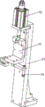
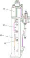
FIG. 1 is a schematic diagram of the present invention.
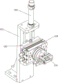
FIG. 2 is a schematic diagram of a turntable according to the present invention.
FIG. 3 is a schematic view of the housing and rotor feed mechanism of the present invention.
FIG. 4 is a schematic diagram of a first oil baffle mechanism of the present invention.
FIG. 5 is a schematic diagram of a first oil baffle detection mechanism according to the present invention.
Fig. 6 is a schematic diagram of a second oil baffle mechanism of the present invention.
FIG. 7 is a schematic diagram of a second oil baffle detection mechanism of the present invention.
FIG. 8 is a schematic view of a rotor in-housing mechanism according to the present invention.
Fig. 9 is a schematic view of a rear cover transfer mechanism according to the present invention.
Fig. 10 is a schematic view of the cap assembly mechanism of the present invention.
Fig. 11 is a schematic view of a motor transfer mechanism according to the present invention.
FIG. 12 is a schematic diagram of a motor withstand voltage detecting mechanism according to the present invention.
Fig. 13 is a schematic view of a motor riveting mechanism according to the present invention.
Fig. 14 is a schematic view of a motor turnover mechanism according to the present invention.
Fig. 15 is a schematic diagram of the oiling mechanism of the motor of the present invention.
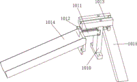
FIG. 16 is a schematic view of a discharge mechanism according to the present invention.
Detailed Description
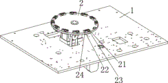
The invention is described in further detail below with reference to the attached drawings and detailed description: referring to fig. 1-16, the full-automatic motor assembly machine comprises a device platform 1, and a turntable 2, a shell and rotor feeding mechanism, a first oil baffle plate punching mechanism, a first oil baffle plate detection mechanism, a second oil baffle plate punching mechanism, a second oil baffle plate detection mechanism, a rotor feeding mechanism, a rear cover conveying mechanism, a rear cover mounting mechanism, a motor transfer mechanism, a blanking track 11, a motor pressure-resistant detection mechanism, a motor riveting mechanism, a motor turnover mechanism, a motor oiling mechanism and a discharging mechanism which are arranged on the device platform.
The rotary table 2 rotates and sets up on the equipment platform 1, simultaneously with set up be in motor cooperation on the equipment platform 1 is connected, be provided with a plurality of stopper subassemblies on the rotary table 2, the stopper subassembly is including setting up last stopper 21 on the rotary table 2 top surface and setting up lower stopper 22 on the rotary table 2 bottom surface, last casing spacing groove 23 and rotor spacing groove 24 of having seted up on the stopper 21 simultaneously on the rotary table 2 respectively with casing spacing groove with the through-hole that the rotor spacing groove corresponds No. one the through-hole of correspondence has been seted up on the lower stopper with No. two through-holes that the through-hole corresponds.
The shell and rotor feeding mechanism comprises a shell conveying rail 311, a second motor 312, a first support 313, a first cylinder 314, a connecting block 315, a second cylinder 316, a first manipulator 317, a rotor conveying rail 321, a third motor 322, a second support 323, a third cylinder 324, a second connecting block 325, a fourth cylinder 326 and a second manipulator 327, wherein the shell conveying rail, the rotor conveying rail, the first support and the second support are fixedly arranged on the equipment platform, the second motor is connected with the shell conveying rail in a matched manner, the third motor is connected with the rotor conveying rail in a matched manner, the first cylinder is arranged on the first support, the first connecting block is connected with the first cylinder in a matched manner, the second cylinder is fixedly arranged on the first connecting block, the first manipulator is connected with the second cylinder in a matched manner, the third cylinder is arranged on the second support, the second cylinder is connected with the third cylinder in a matched manner, and the fourth cylinder is fixedly arranged on the second connecting block and the fourth cylinder is connected with the fourth connecting block in a matched manner.
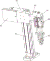
The first oil baffle mechanism comprises a third bracket 41, a first oil baffle material rack 42, a fifth cylinder 43, a first punching head 44 and a first material pulling structure, the third bracket is arranged on the equipment platform, the first oil baffle material rack, the fifth cylinder and the first material pulling structure are all arranged on the third bracket, the first punching head is matched and connected with the fifth cylinder, the first material pulling structure comprises a first sliding rail 451, a first sliding block 452, a first supporting column 453, a first supporting block 454, a first compression block 455, a third connecting block 456, a sixth cylinder 457 and a seventh cylinder 458, the first sliding rail 451 is arranged on the third bracket 41, the first sliding block 452 is in sliding connection with the first sliding rail 451, a groove for the first oil baffle material strip to pass through is formed in the first sliding block 452, the first supporting column is arranged on the top surface of the first sliding block, the first supporting block is matched and arranged on the first sliding block, the first sliding block is matched and connected with the first sliding block, the first sliding block is arranged on the first sliding block, the first sliding block is matched and connected with the third sliding block, and the first sliding block is matched and connected with the third sliding block.
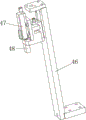
The oil baffle detection mechanism comprises a fourth bracket 46, an eighth cylinder 47 and a detection head 48, wherein the fourth bracket is fixedly arranged on the equipment platform, the eighth cylinder is arranged on the fourth bracket, and the detection head is connected with the eighth cylinder in a matched manner.
The second oil baffle mechanism comprises a fifth support 51, a second oil baffle material rack 52, a ninth air cylinder 53, a second punching head 54 and a second drawing structure, the fifth support is arranged on the equipment platform, the second oil baffle material rack, the ninth air cylinder and the second drawing structure are all arranged on the fifth support, the second punching head is matched and connected with the ninth air cylinder, the second drawing structure comprises a second sliding rail 551, a second sliding block 552, a second supporting column 553, a second supporting block 554, a second compressing block 555, a fourth connecting block 556, a tenth air cylinder 557 and an eleventh air cylinder 558, the second sliding rail is arranged on the fifth support, the second sliding block is slidably connected with the second sliding rail, a second groove for the second oil baffle material strip to pass through is formed in the second sliding block, the second supporting column is arranged on the second sliding block top surface, the second sliding block is matched and arranged on the second supporting column, the second sliding block is matched and connected with the fourth sliding block, the second sliding block is arranged on the second sliding block, the fourth sliding block is matched and connected with the fourth air cylinder.
The second oil baffle detection mechanism comprises a sixth support 56, a twelve air cylinder 57 and a second detection head 58, wherein the sixth support is fixedly arranged on the equipment platform, the twelve air cylinder is arranged on the sixth support, and the second detection head is connected with the twelve air cylinder in a matched mode.
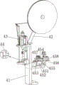
The rotor is gone into casing mechanism and is included No. seven support 61, thirteen's cylinder 62, no. five connecting blocks 63, fourteen's cylinder 64, no. three manipulator 65, blanking pipe 66 and rotor and add lubricating oil mechanism, no. seven support is fixed to be set up on the equipment platform, thirteen's cylinder the blanking pipe with rotor adds lubricating oil mechanism and all sets up on the No. seven support, no. five connecting blocks with thirteen's cylinder cooperation is connected, fourteen's cylinder is fixed to be set up on No. five connecting blocks, no. three manipulator with fourteen's cylinder cooperation is connected, the blanking pipe is last to have seted up into the silo, rotor adds lubricating oil mechanism and includes fifteen's cylinder 671, no. three support post 672, no. three support block 673, lubricating oil tank 674, lubricating pipe 675 and oiling switch, no. three support post is fixed to be set up on the No. seven support, no. three support post sliding connection is in on No. three support post, fifteen's cylinder is fixed to be set up on the bottom surface of No. three support block, no. fourteen cylinder is fixed to be connected with lubricating oil tank cooperation respectively.
The rear cover conveying mechanism includes a rear cover conveying rail 71 provided on the apparatus platform 1 and a motor No. four 72 mated with the rear cover conveying rail 71.
The back cover mechanism comprises a No. eight support 73, a No. sixteen air cylinder 74, a No. six connecting block 75, a No. seventeen air cylinder 76 and a No. four manipulator 77, wherein the No. eight support is arranged on the equipment platform, the No. sixteen air cylinder is arranged on the No. eight support, the No. six connecting block is connected with the air cylinder rod of the No. sixteen air cylinder in a matched mode, the No. seventeen air cylinder is arranged on the No. six connecting block, and the No. four manipulator is connected with the No. seventeen air cylinder in a matched mode.
The motor transfer mechanism comprises a nine-support 81, a four-support block 82, an eighteen air cylinder 83, a seven-connection block 84, a slide bar 85, a nineteenth air cylinder 86 and a five-manipulator 87, wherein the nine-support block is arranged on the equipment platform, the four-support block is arranged on the nine-support block, the eighteen air cylinder is arranged on the four-support block, the slide bar is slidably connected on the four-support block, the seven-connection block is connected with the slide bar in a matched manner, the nineteenth air cylinder is arranged on the seven-connection block in a matched manner, and the five-manipulator is connected with the nineteenth air cylinder in a matched manner.
The blanking track 11 is arranged on the equipment platform 1, and the blanking track 11 is connected with a large motor arranged on the equipment platform 1 in a matched mode.
The motor withstand voltage detection mechanism comprises a tenth bracket 91, a twenty-number air cylinder 92, a third sliding block 93 and a third detection head 94, wherein the tenth bracket is arranged on the equipment platform, the twenty-number air cylinder is fixedly arranged on the tenth bracket, the third sliding block is slidably connected on the tenth bracket and is matched and connected with the twenty-number air cylinder, and the third detection head is matched and connected with the third sliding block.
The motor riveting mechanism comprises an eleven-number bracket 95, a twenty-first air cylinder 96, a fourth slider 97 and a riveting head 98, wherein the eleven-number bracket is arranged on the equipment platform, the twenty-first air cylinder is fixedly arranged on the eleven-number bracket, the fourth slider is slidably connected on the eleven-number bracket and is matched and connected with the twenty-first air cylinder, and the riveting head is matched and connected with the fourth slider.
The motor turnover mechanism comprises a twelve-bracket 101, a twenty-second air cylinder 102, a five-slider 103, a five-motor 104 and a six-manipulator 105, wherein the twelve-bracket is arranged on the equipment platform, the twenty-second air cylinder is fixedly arranged on the twelve-bracket, the four-slider is slidably connected on the twelve-bracket and is matched and connected with the twenty-second air cylinder, the five-motor is arranged on the five-slider, and the six-manipulator is matched and connected with the five-motor.
The motor oiling mechanism comprises a thirteenth bracket 106, a twenty-third air cylinder 107, an eight connecting block 108 and an oiling pipe 109, wherein the thirteenth bracket is arranged on the equipment platform, the twenty-third air cylinder is fixedly arranged on the thirteenth bracket, the eight connecting block is connected with the twenty-third air cylinder in a matched manner, the oiling pipe is arranged on the eight connecting block, and an oiling head is arranged on the oiling pipe.
The discharging mechanism comprises a fourteen-numbered support 1010, a twenty-fourth air cylinder 1011, a nine-numbered connecting block 1012, a material groove 1013, a qualified product blanking slide 1014 and a defective product blanking slide 1015, wherein the fourteen-numbered support is arranged on the equipment platform, the twenty-fourth air cylinder and the defective product blanking slide are fixedly arranged on the fourteen-numbered support, the nine-numbered connecting block is arranged on the twenty-fourth air cylinder, the qualified product blanking slide is arranged on the nine-numbered connecting block, and the material groove is in sliding connection with the fourteen-numbered support and is in matched connection with the twenty-fourth air cylinder.
And the equipment platform is also provided with a motor virtual position detection mechanism for detecting the assembled motor.
The sensor is correspondingly arranged in each mechanism, after the sensor senses that the product moves to the corresponding position, the turntable stops rotating, the turntable continues rotating by a moving angle after the operation of the position is finished, and the device is circulated in such a way, and meanwhile, the whole device is controlled by the control unit, so that the related content of the section is in the prior art and is not excessively repeated.
The assembling method for assembling the motor by adopting the full-automatic motor assembly machine comprises the following steps of: (1) The shell is conveyed to the first manipulator through the shell conveying track and is grabbed into a shell limiting groove on the turntable through the first manipulator, and meanwhile, the rotor is conveyed to the second manipulator through the rotor conveying track and is grabbed into a rotor limiting groove on the turntable through the second manipulator; (2) The rotary table rotates to convey the shell and the rotor to the first oil baffle mechanism; (3) The fifth cylinder controls the first punching head to punch downwards, the corresponding first oil baffle plate is punched into the rotor, and the material belt is pulled backwards through the first material pulling structure after punching; (4) The rotary table rotates to convey the shell and the rotor to a first oil baffle detection mechanism; (5) The first detection head is driven to move by the eighth cylinder, and then whether the first oil baffle is installed in place is detected; (6) The rotary table rotates to convey the shell and the rotor to the second oil baffle mechanism; (7) The ninth cylinder controls the second punching head to punch downwards, the corresponding second oil baffle plate is punched into the rotor, and the material belt is pulled backwards through the second material pulling structure after punching; (8) The turntable rotates to convey the shell and the rotor to the second oil baffle detection mechanism; (9) The second detection head is driven to move by the twelve-numbered air cylinder, and then whether the second oil baffle is installed in place is detected; (10) The turntable rotates to convey the shell and the rotor to a shell-in mechanism of the rotor; (11) The thirteenth air cylinder controls the third manipulator to move up and down, the fourteenth air cylinder controls the third manipulator to move horizontally, the third manipulator clamps the rotor to be placed into the blanking pipe, and the blanking pipe is positioned right above the machine shell, so that the rotor directly falls into the machine shell and passes through the machine shell; (12) The turntable rotates to convey the assembled product to the rear cover mounting mechanism, and meanwhile, the rear cover is conveyed to the rear cover mounting mechanism through the rear cover conveying mechanism; (13) The sixteen-number air cylinder controls the horizontal movement of the fourth manipulator, the seventeen-number air cylinder controls the up-and-down movement of the fourth manipulator, and the rear cover of the fourth manipulator clamp is connected with the machine shell in a matched manner; (14) The turntable rotates to convey the assembled product to a motor transfer mechanism; (15) An eighteen air cylinder controls the manipulator number five to move horizontally, a nineteenth air cylinder controls the manipulator number five to move up and down, and the manipulator number five grabs the assembled product and conveys the product to a discharging track; (16) The blanking track drives the assembled product to be conveyed to the motor withstand voltage detection mechanism; (17) The twenty-first cylinder drives the third detection head to move up and down, and whether the motor is installed in place or not is detected; (18) Conveying the assembled product to a motor riveting mechanism by the blanking track, and driving a riveting head to rivet the motor again by a twenty-first cylinder; (19) The motor is transferred to the material tank through the motor turnover mechanism, and when the defective products are detected to be conveyed, the twenty-four cylinder pulls the material tank to the outer side, so that the defective products slide down from the defective product discharging slide way; when the conveyed qualified products are detected, the twenty-fourth air cylinder pushes the material tank to the inner side, the motor is oiled through the motor oiling mechanism, and finally the qualified products slide down through the qualified product blanking slide.
The above embodiments are only for illustrating the technical solution of the present invention, and are not limiting; although the invention has been described in detail with reference to the foregoing embodiments, it will be understood by those of ordinary skill in the art that: the technical scheme described in the foregoing embodiments can be modified or some technical features thereof can be replaced by equivalents; such modifications and substitutions do not depart from the spirit and scope of the technical solutions of the embodiments of the present invention.
Claims (2)
1. Full-automatic motor assembly machine, its characterized in that: the device comprises a device platform, a rotary table, a shell and rotor feeding mechanism, a first oil baffle punching detection mechanism, a second oil baffle punching detection mechanism, a rotor shell feeding mechanism, a rear cover conveying mechanism, a rear cover mounting mechanism, a motor transfer mechanism, a discharging track, a motor pressure-resistant detection mechanism, a motor riveting mechanism, a motor overturning mechanism, a motor oiling mechanism and a discharging mechanism, wherein the rotary table, the shell and rotor feeding mechanism, the first oil baffle punching detection mechanism, the second oil baffle punching detection mechanism, the rotor shell feeding mechanism, the rear cover conveying mechanism, the rear cover mounting mechanism, the motor transfer mechanism, the discharging track, the motor pressure-resistant detection mechanism, the motor riveting mechanism, the motor overturning mechanism and the discharging mechanism are arranged on the device platform; the rotary table is rotationally arranged on the equipment platform and is connected with a first motor arranged on the equipment platform in a matched manner, 11 groups of limiting block assemblies are arranged on the rotary table, each limiting block assembly comprises an upper limiting block arranged on the top surface of the rotary table and a lower limiting block arranged on the bottom surface of the rotary table, a shell limiting groove and a rotor limiting groove are formed in the upper limiting block, a first through hole corresponding to the shell limiting groove and a first through hole corresponding to the rotor limiting groove are formed in the rotary table respectively, and a second through hole corresponding to the first through hole is formed in the lower limiting block; the shell and rotor feeding mechanism comprises a shell conveying track, a second motor, a first support, a first cylinder, a first connecting block, a second cylinder, a first manipulator, a rotor conveying track, a third motor, a second support, a third cylinder, a second connecting block, a fourth cylinder and a second manipulator, wherein the shell conveying track, the rotor conveying track, the first support and the second support are fixedly arranged on the equipment platform, the second motor is connected with the shell conveying track in a matched manner, the third motor is connected with the rotor conveying track in a matched manner, the first cylinder is arranged on the first support, the first connecting block is connected with the first cylinder in a matched manner, the second cylinder is fixedly arranged on the first connecting block, the first manipulator is connected with the second cylinder in a matched manner, the third cylinder is arranged on the second support, the second connecting block is connected with the third cylinder in a matched manner, and the fourth cylinder is fixedly arranged on the second cylinder, and the fourth manipulator is connected with the fourth connecting block in a matched manner. The first oil baffle mechanism comprises a third bracket, a first oil baffle material rack, a fifth cylinder, a first punching head and a first material pulling structure, wherein the third bracket is arranged on the equipment platform, the first oil baffle material rack, the fifth cylinder and the first material pulling structure are all arranged on the third bracket, the first punching head is connected with the fifth cylinder in a matched manner, the first material pulling structure comprises a first sliding rail, a first sliding block, a first supporting column, a first supporting block, a first compression block, a third connecting block, a sixth cylinder and a seventh cylinder, the first sliding rail is arranged on the third bracket, the first sliding block is slidably connected on the first sliding rail, a first groove for the first oil baffle material bar to pass through is formed in the first sliding rail, the first supporting column is arranged on the top surface of the first sliding block, the first supporting block is arranged on the first supporting column in a matched manner, the sixth cylinder is arranged on the first supporting block, the first sliding block is connected with the first sliding block in a matched manner, the first sliding block is connected with the seventh cylinder in a matched manner, and the first sliding block is connected with the third sliding block in a matched manner; the first oil baffle detection mechanism comprises a fourth bracket, an eighth cylinder and a first detection head, wherein the fourth bracket is fixedly arranged on the equipment platform, the eighth cylinder is arranged on the fourth bracket, and the first detection head is connected with the eighth cylinder in a matched manner; the second oil baffle mechanism comprises a fifth bracket, a second oil baffle material rack, a ninth air cylinder, a second punching head and a second material pulling structure, the fifth bracket is arranged on the equipment platform, the second oil baffle material rack, the ninth air cylinder and the second material pulling structure are all arranged on the fifth bracket, the second punching head is connected with the ninth air cylinder in a matched mode, the second material pulling structure comprises a second sliding rail, a second sliding block, a second supporting column, a second supporting block, a second compression block, a fourth connecting block, a tenth air cylinder and an eleventh air cylinder, the second sliding rail is arranged on the fifth bracket, the second sliding block is connected with the second sliding rail in a sliding mode, a second groove for the second oil baffle material bar to penetrate through is formed in the second sliding block, the second supporting block is arranged on the top surface of the second sliding block in a matched mode, the tenth air cylinder is arranged on the second supporting block in a matched mode, the second sliding block is connected with the tenth air cylinder in a matched mode, and the fourth sliding block is connected with the eleventh air cylinder in a matched mode; the second oil baffle detection mechanism comprises a sixth support, a twelve air cylinders and a second detection head, wherein the sixth support is fixedly arranged on the equipment platform, the twelve air cylinders are arranged on the sixth support, and the second detection head is connected with the twelve air cylinders in a matched mode; the rotor casing entering mechanism comprises a seventh bracket, a thirteenth cylinder, a fifth connecting block, a fourteen cylinder, a third manipulator, a blanking pipe and a rotor lubricating oil adding mechanism, wherein the seventh bracket is fixedly arranged on the equipment platform, the thirteenth cylinder, the blanking pipe and the rotor lubricating oil adding mechanism are all arranged on the seventh bracket, the fifth connecting block is connected with the thirteenth cylinder in a matched manner, the fourteen cylinder is fixedly arranged on the fifth connecting block, the third manipulator is connected with the fourteen cylinder in a matched manner, the blanking pipe is provided with a feeding groove, the rotor lubricating oil adding mechanism comprises a fifteen cylinder, a third supporting column, a third supporting block, a lubricating oil tank, a lubricating pipe and a lubricating switch, the third supporting column is fixedly arranged on the seventh bracket, the third supporting block is slidably connected on the third supporting column, the fifteen cylinder is fixedly arranged on the bottom surface of the third supporting block, the lubricating oil tank is fixedly arranged on the top surface of the third supporting block, and the lubricating oil tank and the lubricating switch are respectively connected with the lubricating oil tank in a matched manner; the rear cover conveying mechanism comprises a rear cover conveying track arranged on the equipment platform and a fourth motor matched with the rear cover conveying track; the rear cover mounting mechanism comprises a No. eight support, a No. sixteen air cylinder, a No. six connecting block, a No. seventeen air cylinder and a No. four manipulator, wherein the No. eight support is arranged on the equipment platform, the No. sixteen air cylinder is arranged on the No. eight support, the No. six connecting block is connected with the air cylinder rod of the No. sixteen air cylinder in a matched manner, the No. seventeen air cylinder is arranged on the No. six connecting block, and the No. four manipulator is connected with the No. seventeen air cylinder in a matched manner; the motor transfer mechanism comprises a nine-bracket, a four-supporting block, an eighteen-cylinder, a seven-connecting block, a slide bar, a nineteenth-cylinder and a five-manipulator, wherein the nine-bracket is arranged on the equipment platform, the four-supporting block is arranged on the nine-bracket, the eighteen-cylinder is arranged on the four-supporting block, the slide bar is slidably connected on the four-supporting block, the seven-connecting block is connected with the slide bar in a matched manner, the nineteenth-cylinder is arranged on the seven-connecting block in a matched manner, and the five-manipulator is connected with the nineteenth-cylinder in a matched manner. The blanking track is arranged on the equipment platform and is connected with a large motor arranged on the equipment platform in a matched manner;
the motor withstand voltage detection mechanism comprises a tenth bracket, a twenty-number air cylinder, a third sliding block and a third detection head, wherein the tenth bracket is arranged on the equipment platform, the twenty-number air cylinder is fixedly arranged on the tenth bracket, the third sliding block is slidably connected on the tenth bracket and is matched and connected with the twenty-number air cylinder, and the third detection head is matched and connected with the third sliding block; the motor riveting mechanism comprises an eleven-number bracket, an eleven-number air cylinder, a fourth slider and a riveting head, wherein the eleven-number bracket is arranged on the equipment platform, the twenty-first air cylinder is fixedly arranged on the eleven-number bracket, the fourth slider is slidably connected on the eleven-number bracket and is matched and connected with the twenty-first air cylinder, and the riveting head is matched and connected with the fourth slider;
the motor turnover mechanism comprises a twelve-bracket, twenty-second cylinders, a five-slider, a five-motor and a six-manipulator, wherein the twelve-bracket is arranged on the equipment platform, the twenty-second cylinders are fixedly arranged on the twelve-bracket, the four-slider is slidably connected on the twelve-bracket and is matched and connected with the twenty-second cylinders, the five-motor is arranged on the five-slider, and the six-manipulator is matched and connected with the five-motor; the motor oiling mechanism comprises a thirteenth bracket, a twenty-third air cylinder, an eight connecting block and an oiling pipe, wherein the thirteenth bracket is arranged on the equipment platform, the twenty-third air cylinder is fixedly arranged on the thirteenth bracket, the eight connecting block is connected with the twenty-third air cylinder in a matched manner, the oiling pipe is arranged on the eight connecting block, and an oiling head is arranged on the oiling pipe; the discharging mechanism comprises a fourteen-numbered support, a twenty-fourth-numbered cylinder, a nine-numbered connecting block, a material groove, a qualified product blanking slide way and a defective product blanking slide way, wherein the fourteen-numbered support is arranged on the equipment platform, the twenty-fourth-numbered cylinder and the defective product blanking slide way are fixedly arranged on the fourteen-numbered support, the nine-numbered connecting block is arranged on the twenty-fourth-numbered cylinder, the qualified product blanking slide way is arranged on the nine-numbered connecting block, and the material groove is in sliding connection with the fourteen-numbered support and is in matched connection with the twenty-fourth-numbered cylinder.
2. An assembling method for assembling a motor by using the fully automatic motor assembling machine according to claim 1, comprising the following steps: (1) The shell is conveyed to the first manipulator through the shell conveying track and is grabbed into a shell limiting groove on the turntable through the first manipulator, and meanwhile, the rotor is conveyed to the second manipulator through the rotor conveying track and is grabbed into a rotor limiting groove on the turntable through the second manipulator; (2) The rotary table rotates to convey the shell and the rotor to the first oil baffle mechanism; (3) The fifth cylinder controls the first punching head to punch downwards, the corresponding first oil baffle plate is punched into the rotor, and the material belt is pulled backwards through the first material pulling structure after punching; (4) The rotary table rotates to convey the shell and the rotor to a first oil baffle detection mechanism; (5) The first detection head is driven to move by the eighth cylinder, and then whether the first oil baffle is installed in place is detected; (6) The rotary table rotates to convey the shell and the rotor to the second oil baffle mechanism; (7) The ninth cylinder controls the second punching head to punch downwards, the corresponding second oil baffle plate is punched into the rotor, and the material belt is pulled backwards through the second material pulling structure after punching; (8) The turntable rotates to convey the shell and the rotor to the second oil baffle detection mechanism; (9) The second detection head is driven to move by the twelve-numbered air cylinder, and then whether the second oil baffle is installed in place is detected; (10) The turntable rotates to convey the shell and the rotor to a shell-in mechanism of the rotor; (11) The thirteenth air cylinder controls the third manipulator to move up and down, the fourteenth air cylinder controls the third manipulator to move horizontally, the third manipulator clamps the rotor to be placed into the blanking pipe, and the blanking pipe is positioned right above the machine shell, so that the rotor directly falls into the machine shell and passes through the machine shell; (12) The turntable rotates to convey the assembled product to the rear cover mounting mechanism, and meanwhile, the rear cover is conveyed to the rear cover mounting mechanism through the rear cover conveying mechanism; (13) The sixteen-number air cylinder controls the horizontal movement of the fourth manipulator, the seventeen-number air cylinder controls the up-and-down movement of the fourth manipulator, and the rear cover of the fourth manipulator clamp is connected with the machine shell in a matched manner; (14) The turntable rotates to convey the assembled product to a motor transfer mechanism; (15) An eighteen air cylinder controls the manipulator number five to move horizontally, a nineteenth air cylinder controls the manipulator number five to move up and down, and the manipulator number five grabs the assembled product and conveys the product to a discharging track; (16) The blanking track drives the assembled product to be conveyed to the motor withstand voltage detection mechanism; (17) The twenty-first cylinder drives the third detection head to move up and down, and whether the motor is installed in place or not is detected; (18) Conveying the assembled product to a motor riveting mechanism by the blanking track, and driving a riveting head to rivet the motor again by a twenty-first cylinder; (19) The motor is transferred to the material tank through the motor turnover mechanism, and when the defective products are detected to be conveyed, the twenty-four cylinder pulls the material tank to the outer side, so that the defective products slide down from the defective product discharging slide way; when the conveyed qualified products are detected, the twenty-fourth air cylinder pushes the material tank to the inner side, the motor is oiled through the motor oiling mechanism, and finally the qualified products slide down through the qualified product blanking slide.
Priority Applications (1)
| Application Number | Priority Date | Filing Date | Title |
|---|---|---|---|
| CN201710989612.1A CN107498307B (en) | 2017-10-23 | 2017-10-23 | Full-automatic motor assembly machine and assembly method thereof |
Applications Claiming Priority (1)
| Application Number | Priority Date | Filing Date | Title |
|---|---|---|---|
| CN201710989612.1A CN107498307B (en) | 2017-10-23 | 2017-10-23 | Full-automatic motor assembly machine and assembly method thereof |
Publications (2)
| Publication Number | Publication Date |
|---|---|
| CN107498307A CN107498307A (en) | 2017-12-22 |
| CN107498307B true CN107498307B (en) | 2023-05-16 |
Family
ID=60702017
Family Applications (1)
| Application Number | Title | Priority Date | Filing Date |
|---|---|---|---|
| CN201710989612.1A Active CN107498307B (en) | 2017-10-23 | 2017-10-23 | Full-automatic motor assembly machine and assembly method thereof |
Country Status (1)
| Country | Link |
|---|---|
| CN (1) | CN107498307B (en) |
Families Citing this family (5)
| Publication number | Priority date | Publication date | Assignee | Title |
|---|---|---|---|---|
| CN109660082B (en) * | 2019-01-31 | 2023-10-20 | 重庆昆旺电子有限责任公司 | Motor assembly process |
| CN109940383A (en) * | 2019-04-11 | 2019-06-28 | 何威 | The slim assembly line of micro machine |
| CN110460203B (en) * | 2019-08-12 | 2021-06-18 | 宁波市鸿林自动化机械有限公司 | Automatic assembly equipment of 550 direct current motor |
| CN110561090A (en) * | 2019-09-28 | 2019-12-13 | 赣州中科拓又达智能装备科技有限公司 | Motor casing automatic assembly check out test set |
| CN112643336A (en) * | 2020-12-30 | 2021-04-13 | 乐清野岛机电有限公司 | Full-automatic assembly device of motor automatic machine |
Family Cites Families (6)
| Publication number | Priority date | Publication date | Assignee | Title |
|---|---|---|---|---|
| DE2801542A1 (en) * | 1977-01-17 | 1978-07-20 | Bicc Ltd | ELECTRIC CABLE |
| US5539977A (en) * | 1993-10-29 | 1996-07-30 | Sanyo Electric Co., Ltd. | Apparatus and method for automatically mounting electronic parts |
| US20090113999A1 (en) * | 2007-03-08 | 2009-05-07 | General Electric Company | Method for Testing a Rotor and Stator Assembly |
| US8479379B2 (en) * | 2008-11-03 | 2013-07-09 | Carefusion 202, Inc. | Roots-type blower rotor alignment apparatus |
| CN104348310B (en) * | 2014-11-12 | 2017-01-25 | 中国十九冶集团有限公司南京分公司 | Mounting method for field rotor penetration of TRT (Top Gas Pressure Recovery Turbine) generator |
| CN207255661U (en) * | 2017-10-23 | 2018-04-20 | 浙江盛越电子科技有限公司 | Full-automatic motor total installed capacity |
-
2017
- 2017-10-23 CN CN201710989612.1A patent/CN107498307B/en active Active
Also Published As
| Publication number | Publication date |
|---|---|
| CN107498307A (en) | 2017-12-22 |
Similar Documents
| Publication | Publication Date | Title |
|---|---|---|
| CN107498307B (en) | Full-automatic motor assembly machine and assembly method thereof | |
| CN105798609B (en) | Limit switch kludge | |
| CN101474617B (en) | Improved automatic grading conveying device for micro-bearing | |
| CN106112520A (en) | A kind of non-reversing device for starting automatic assembling machine bed | |
| CN207711672U (en) | A kind of packaging container lid automatic hot foil printing machine | |
| CN102728807B (en) | Automatic picking and raking equipment of zinc die-casting machine | |
| CN111842630A (en) | Be used for high-efficient punching a hole of many batches of copper sheathing and automatic unloading equipment of going up | |
| CN201324724Y (en) | Automatic classified conveying device for miniature bearing | |
| CN209014237U (en) | A kind of electronic product vibration test case | |
| CN103722089A (en) | Automatic assembling machine for lamp bracket | |
| CN109048334B (en) | Needle assembly equipment for animals | |
| CN110614499B (en) | Semi-automatic pin assembling mechanism | |
| CN104900981A (en) | Automatic antenna oscillator assembler | |
| CN112008369B (en) | Automatic bearing press fitting equipment | |
| CN104355108A (en) | Separation device for canned food | |
| CN206316752U (en) | The position-limited box kludge of car door limiter | |
| CN106696289B (en) | Full-automatic pointer heat transfer printing assembly all-in-one machine | |
| CN203238480U (en) | Curtain cutting machine | |
| CN108757752B (en) | Automatic full-automatic assembly machine for door and window bearings | |
| CN111865009A (en) | Automatic end plate pressing machine for motor stator | |
| CN201690992U (en) | Turntable type manipulator | |
| CN109115085A (en) | A kind of full-automatic bearing inner diameter measurement machine | |
| CN206201662U (en) | A kind of handset touch panel automatic screen printer | |
| CN108336876A (en) | A kind of rotor coiling equipment | |
| CN107984192A (en) | Machine shaft top gear press-in device and its pressing method |
Legal Events
| Date | Code | Title | Description |
|---|---|---|---|
| PB01 | Publication | ||
| PB01 | Publication | ||
| SE01 | Entry into force of request for substantive examination | ||
| SE01 | Entry into force of request for substantive examination | ||
| GR01 | Patent grant | ||
| GR01 | Patent grant |