CN107360379B - Information communication method - Google Patents
Information communication method Download PDFInfo
- Publication number
- CN107360379B CN107360379B CN201710695427.1A CN201710695427A CN107360379B CN 107360379 B CN107360379 B CN 107360379B CN 201710695427 A CN201710695427 A CN 201710695427A CN 107360379 B CN107360379 B CN 107360379B
- Authority
- CN
- China
- Prior art keywords
- information
- diagram showing
- user
- exposure
- sound
- Prior art date
- Legal status (The legal status is an assumption and is not a legal conclusion. Google has not performed a legal analysis and makes no representation as to the accuracy of the status listed.)
- Active
Links
- 238000004891 communication Methods 0.000 title claims abstract description 566
- 230000006854 communication Effects 0.000 title claims abstract description 566
- 238000000034 method Methods 0.000 title claims abstract description 462
- 230000008859 change Effects 0.000 claims abstract description 212
- 238000004590 computer program Methods 0.000 claims description 15
- 239000004576 sand Substances 0.000 claims 3
- 238000010586 diagram Methods 0.000 description 637
- 230000005540 biological transmission Effects 0.000 description 393
- 238000003384 imaging method Methods 0.000 description 310
- 230000008569 process Effects 0.000 description 233
- 238000012545 processing Methods 0.000 description 214
- 230000003287 optical effect Effects 0.000 description 73
- 230000004397 blinking Effects 0.000 description 65
- 230000006870 function Effects 0.000 description 64
- 238000003860 storage Methods 0.000 description 58
- 238000005286 illumination Methods 0.000 description 49
- 230000008054 signal transmission Effects 0.000 description 46
- 238000001514 detection method Methods 0.000 description 45
- 230000033001 locomotion Effects 0.000 description 44
- 239000002131 composite material Substances 0.000 description 36
- 238000007726 management method Methods 0.000 description 36
- 238000012986 modification Methods 0.000 description 36
- 230000004048 modification Effects 0.000 description 36
- 238000010411 cooking Methods 0.000 description 33
- 230000000694 effects Effects 0.000 description 26
- 238000009826 distribution Methods 0.000 description 24
- 238000012790 confirmation Methods 0.000 description 21
- 230000002829 reductive effect Effects 0.000 description 20
- 230000002093 peripheral effect Effects 0.000 description 16
- 238000012937 correction Methods 0.000 description 15
- 238000004458 analytical method Methods 0.000 description 14
- 238000004140 cleaning Methods 0.000 description 14
- 210000003128 head Anatomy 0.000 description 13
- 108010076504 Protein Sorting Signals Proteins 0.000 description 12
- 238000009434 installation Methods 0.000 description 11
- 230000035945 sensitivity Effects 0.000 description 11
- 238000002156 mixing Methods 0.000 description 10
- 230000004044 response Effects 0.000 description 10
- 230000003190 augmentative effect Effects 0.000 description 9
- 230000008901 benefit Effects 0.000 description 8
- 230000001413 cellular effect Effects 0.000 description 8
- 230000007613 environmental effect Effects 0.000 description 7
- 239000004973 liquid crystal related substance Substances 0.000 description 7
- 238000012546 transfer Methods 0.000 description 7
- 230000007704 transition Effects 0.000 description 7
- 238000013459 approach Methods 0.000 description 6
- 239000000470 constituent Substances 0.000 description 6
- 235000013305 food Nutrition 0.000 description 6
- 238000003825 pressing Methods 0.000 description 6
- 238000005096 rolling process Methods 0.000 description 6
- XLYOFNOQVPJJNP-UHFFFAOYSA-N water Substances O XLYOFNOQVPJJNP-UHFFFAOYSA-N 0.000 description 6
- 230000003247 decreasing effect Effects 0.000 description 5
- 210000001508 eye Anatomy 0.000 description 5
- 230000007246 mechanism Effects 0.000 description 5
- 241000209094 Oryza Species 0.000 description 4
- 235000007164 Oryza sativa Nutrition 0.000 description 4
- 230000001133 acceleration Effects 0.000 description 4
- 230000001771 impaired effect Effects 0.000 description 4
- 239000000463 material Substances 0.000 description 4
- 238000012544 monitoring process Methods 0.000 description 4
- 230000033764 rhythmic process Effects 0.000 description 4
- 235000009566 rice Nutrition 0.000 description 4
- 238000004904 shortening Methods 0.000 description 4
- 238000000060 site-specific infrared dichroism spectroscopy Methods 0.000 description 4
- 230000004913 activation Effects 0.000 description 3
- 230000006399 behavior Effects 0.000 description 3
- 230000015572 biosynthetic process Effects 0.000 description 3
- 230000006835 compression Effects 0.000 description 3
- 238000007906 compression Methods 0.000 description 3
- 230000007423 decrease Effects 0.000 description 3
- 238000001914 filtration Methods 0.000 description 3
- 238000004519 manufacturing process Methods 0.000 description 3
- 238000002360 preparation method Methods 0.000 description 3
- 230000002441 reversible effect Effects 0.000 description 3
- 238000010079 rubber tapping Methods 0.000 description 3
- 238000005070 sampling Methods 0.000 description 3
- 239000004065 semiconductor Substances 0.000 description 3
- 238000003786 synthesis reaction Methods 0.000 description 3
- 230000002123 temporal effect Effects 0.000 description 3
- 208000032041 Hearing impaired Diseases 0.000 description 2
- 230000009471 action Effects 0.000 description 2
- 230000002411 adverse Effects 0.000 description 2
- 230000007175 bidirectional communication Effects 0.000 description 2
- 230000002457 bidirectional effect Effects 0.000 description 2
- 238000003745 diagnosis Methods 0.000 description 2
- 239000003814 drug Substances 0.000 description 2
- 238000005516 engineering process Methods 0.000 description 2
- 238000000691 measurement method Methods 0.000 description 2
- 238000001454 recorded image Methods 0.000 description 2
- 239000000725 suspension Substances 0.000 description 2
- 230000001360 synchronised effect Effects 0.000 description 2
- 230000002194 synthesizing effect Effects 0.000 description 2
- 230000000007 visual effect Effects 0.000 description 2
- 101100172132 Mus musculus Eif3a gene Proteins 0.000 description 1
- 101100230207 Oryza sativa subsp. japonica GSK1 gene Proteins 0.000 description 1
- 101100202463 Schizophyllum commune SC14 gene Proteins 0.000 description 1
- 206010047571 Visual impairment Diseases 0.000 description 1
- 230000002159 abnormal effect Effects 0.000 description 1
- 238000009825 accumulation Methods 0.000 description 1
- 239000008186 active pharmaceutical agent Substances 0.000 description 1
- 238000007792 addition Methods 0.000 description 1
- 235000013361 beverage Nutrition 0.000 description 1
- 230000000903 blocking effect Effects 0.000 description 1
- 238000005282 brightening Methods 0.000 description 1
- 230000003139 buffering effect Effects 0.000 description 1
- 210000005252 bulbus oculi Anatomy 0.000 description 1
- 238000004364 calculation method Methods 0.000 description 1
- 239000003086 colorant Substances 0.000 description 1
- 238000010276 construction Methods 0.000 description 1
- 230000003111 delayed effect Effects 0.000 description 1
- 238000013461 design Methods 0.000 description 1
- 230000023077 detection of light stimulus Effects 0.000 description 1
- 239000006185 dispersion Substances 0.000 description 1
- 229940079593 drug Drugs 0.000 description 1
- 230000005611 electricity Effects 0.000 description 1
- 239000000284 extract Substances 0.000 description 1
- 239000000945 filler Substances 0.000 description 1
- 230000007274 generation of a signal involved in cell-cell signaling Effects 0.000 description 1
- 239000011521 glass Substances 0.000 description 1
- 230000005484 gravity Effects 0.000 description 1
- 238000010438 heat treatment Methods 0.000 description 1
- 239000004615 ingredient Substances 0.000 description 1
- 238000003780 insertion Methods 0.000 description 1
- 230000037431 insertion Effects 0.000 description 1
- 230000010354 integration Effects 0.000 description 1
- 230000000670 limiting effect Effects 0.000 description 1
- 238000012423 maintenance Methods 0.000 description 1
- QSHDDOUJBYECFT-UHFFFAOYSA-N mercury Chemical compound [Hg] QSHDDOUJBYECFT-UHFFFAOYSA-N 0.000 description 1
- 229910052753 mercury Inorganic materials 0.000 description 1
- 229910052751 metal Inorganic materials 0.000 description 1
- 239000002184 metal Substances 0.000 description 1
- 238000010295 mobile communication Methods 0.000 description 1
- 230000000474 nursing effect Effects 0.000 description 1
- 230000036961 partial effect Effects 0.000 description 1
- 230000000737 periodic effect Effects 0.000 description 1
- 230000010363 phase shift Effects 0.000 description 1
- 230000002265 prevention Effects 0.000 description 1
- 230000009467 reduction Effects 0.000 description 1
- 230000008439 repair process Effects 0.000 description 1
- 238000000926 separation method Methods 0.000 description 1
- 230000011664 signaling Effects 0.000 description 1
- 230000003595 spectral effect Effects 0.000 description 1
- 230000001131 transforming effect Effects 0.000 description 1
- 208000029257 vision disease Diseases 0.000 description 1
- 230000004393 visual impairment Effects 0.000 description 1
- 238000005406 washing Methods 0.000 description 1
- 239000002699 waste material Substances 0.000 description 1
Images


Classifications
-
- H—ELECTRICITY
- H04—ELECTRIC COMMUNICATION TECHNIQUE
- H04B—TRANSMISSION
- H04B10/00—Transmission systems employing electromagnetic waves other than radio-waves, e.g. infrared, visible or ultraviolet light, or employing corpuscular radiation, e.g. quantum communication
- H04B10/11—Arrangements specific to free-space transmission, i.e. transmission through air or vacuum
- H04B10/114—Indoor or close-range type systems
- H04B10/116—Visible light communication
-
- H—ELECTRICITY
- H04—ELECTRIC COMMUNICATION TECHNIQUE
- H04N—PICTORIAL COMMUNICATION, e.g. TELEVISION
- H04N23/00—Cameras or camera modules comprising electronic image sensors; Control thereof
- H04N23/70—Circuitry for compensating brightness variation in the scene
- H04N23/73—Circuitry for compensating brightness variation in the scene by influencing the exposure time
-
- G—PHYSICS
- G06—COMPUTING; CALCULATING OR COUNTING
- G06T—IMAGE DATA PROCESSING OR GENERATION, IN GENERAL
- G06T5/00—Image enhancement or restoration
- G06T5/50—Image enhancement or restoration using two or more images, e.g. averaging or subtraction
-
- H—ELECTRICITY
- H04—ELECTRIC COMMUNICATION TECHNIQUE
- H04L—TRANSMISSION OF DIGITAL INFORMATION, e.g. TELEGRAPHIC COMMUNICATION
- H04L12/00—Data switching networks
- H04L12/28—Data switching networks characterised by path configuration, e.g. LAN [Local Area Networks] or WAN [Wide Area Networks]
- H04L12/46—Interconnection of networks
- H04L12/4604—LAN interconnection over a backbone network, e.g. Internet, Frame Relay
- H04L12/462—LAN interconnection over a bridge based backbone
- H04L12/4625—Single bridge functionality, e.g. connection of two networks over a single bridge
-
- H—ELECTRICITY
- H04—ELECTRIC COMMUNICATION TECHNIQUE
- H04N—PICTORIAL COMMUNICATION, e.g. TELEVISION
- H04N21/00—Selective content distribution, e.g. interactive television or video on demand [VOD]
- H04N21/40—Client devices specifically adapted for the reception of or interaction with content, e.g. set-top-box [STB]; Operations thereof
- H04N21/41—Structure of client; Structure of client peripherals
- H04N21/4104—Peripherals receiving signals from specially adapted client devices
- H04N21/4131—Peripherals receiving signals from specially adapted client devices home appliance, e.g. lighting, air conditioning system, metering devices
-
- H—ELECTRICITY
- H04—ELECTRIC COMMUNICATION TECHNIQUE
- H04N—PICTORIAL COMMUNICATION, e.g. TELEVISION
- H04N21/00—Selective content distribution, e.g. interactive television or video on demand [VOD]
- H04N21/40—Client devices specifically adapted for the reception of or interaction with content, e.g. set-top-box [STB]; Operations thereof
- H04N21/43—Processing of content or additional data, e.g. demultiplexing additional data from a digital video stream; Elementary client operations, e.g. monitoring of home network or synchronising decoder's clock; Client middleware
- H04N21/436—Interfacing a local distribution network, e.g. communicating with another STB or one or more peripheral devices inside the home
- H04N21/43615—Interfacing a Home Network, e.g. for connecting the client to a plurality of peripherals
-
- H—ELECTRICITY
- H04—ELECTRIC COMMUNICATION TECHNIQUE
- H04N—PICTORIAL COMMUNICATION, e.g. TELEVISION
- H04N21/00—Selective content distribution, e.g. interactive television or video on demand [VOD]
- H04N21/40—Client devices specifically adapted for the reception of or interaction with content, e.g. set-top-box [STB]; Operations thereof
- H04N21/47—End-user applications
- H04N21/488—Data services, e.g. news ticker
- H04N21/4882—Data services, e.g. news ticker for displaying messages, e.g. warnings, reminders
-
- H—ELECTRICITY
- H04—ELECTRIC COMMUNICATION TECHNIQUE
- H04N—PICTORIAL COMMUNICATION, e.g. TELEVISION
- H04N23/00—Cameras or camera modules comprising electronic image sensors; Control thereof
- H04N23/60—Control of cameras or camera modules
- H04N23/61—Control of cameras or camera modules based on recognised objects
-
- H—ELECTRICITY
- H04—ELECTRIC COMMUNICATION TECHNIQUE
- H04B—TRANSMISSION
- H04B10/00—Transmission systems employing electromagnetic waves other than radio-waves, e.g. infrared, visible or ultraviolet light, or employing corpuscular radiation, e.g. quantum communication
- H04B10/11—Arrangements specific to free-space transmission, i.e. transmission through air or vacuum
- H04B10/114—Indoor or close-range type systems
- H04B10/1143—Bidirectional transmission
-
- H—ELECTRICITY
- H04—ELECTRIC COMMUNICATION TECHNIQUE
- H04W—WIRELESS COMMUNICATION NETWORKS
- H04W4/00—Services specially adapted for wireless communication networks; Facilities therefor
- H04W4/50—Service provisioning or reconfiguring
Landscapes
- Engineering & Computer Science (AREA)
- Signal Processing (AREA)
- Multimedia (AREA)
- Computer Networks & Wireless Communication (AREA)
- Physics & Mathematics (AREA)
- Automation & Control Theory (AREA)
- Electromagnetism (AREA)
- General Physics & Mathematics (AREA)
- Theoretical Computer Science (AREA)
- Optical Communication System (AREA)
- Telephonic Communication Services (AREA)
- Selective Calling Equipment (AREA)
- Studio Devices (AREA)
Abstract
An information communication method for acquiring information from a subject, comprising: an exposure time setting step of setting an exposure time of an image sensor so that a bright line corresponding to an exposure line included in the image sensor is generated in accordance with a change in luminance of an object in an image obtained by photographing the object by the image sensor; a bright line image acquisition step of acquiring a bright line image including a bright line by photographing a subject whose brightness has changed with a set exposure time by an image sensor; and an information acquisition step of acquiring information by demodulating data specified by a pattern of the bright line included in the acquired bright line image, wherein the exposure time setting step sets the exposure time to tELet t be the minimum time unit for brightness change of the objectSIn the case of (1), with tE<tSThe exposure time is set.
Description
This application is a divisional application of patent application No. 201380066941.9 filed on 19/6/2015. This application contains the entire contents of the parent application.
Technical Field
The present invention relates to a communication method between a mobile terminal such as a smartphone, a tablet computer, or a mobile phone and a home appliance such as an air conditioner, a lighting device, or a rice cooker.
Background
In recent years, Home Energy Management Systems (HEMS) have been introduced to realize home appliance cooperation functions in which various home appliances are connected to a network, by using a Home Energy Management System (HEMS) having functions of managing the amount of power used in response to environmental problems, or turning ON/OFF power from outside the home, in addition to cooperation of AV home appliances by ip (internet protocol) connection under Ethernet (registered trademark) or wireless lan (local area network). However, there are home appliances that have insufficient computing power and home appliances that are mounted with a communication function that is difficult to implement at low cost.
In order to solve such a problem, patent document 1 describes a technique that enables efficient communication between devices in a limited number of transmission devices by performing communication using a single color light source of a plurality of illumination lights in an optical space transmission device that transmits information to a free space using light.
Prior Art
Patent document
Patent document 1: japanese patent laid-open publication No. 2002-
Disclosure of Invention
Problems to be solved by the invention
However, the above-described conventional system is limited to a case where the device to be used has a 3-color light source such as illumination. The present invention solves the above problems, and provides an information communication method capable of performing communication between a plurality of devices including a device with a small computational effort.
Means for solving the problems
An information communication method according to an aspect of the present invention is an information communication method for acquiring information from a subject, including: an exposure time setting step of setting an exposure time of the image sensor toGenerating a bright line corresponding to an exposure line included in an image sensor in accordance with a change in luminance of the subject in an image obtained by photographing the subject with the image sensor; a bright line image acquisition step of acquiring a bright line image including the bright line by photographing the subject whose luminance changes with the set exposure time by the image sensor; and an information acquisition step of acquiring information by demodulating data specified by a pattern of the bright line included in the acquired bright line image, wherein the exposure time setting step sets the exposure time to tEAnd setting t as the minimum time unit for brightness change of the objectSIn the case of (1), with tE<tSThe exposure time is set.
These general and specific technical aspects may be implemented by a system, a method, an integrated circuit, a computer program, a computer-readable recording medium such as a CD-ROM, or any combination of a system, a method, an integrated circuit, a computer program, and a recording medium.
According to the present invention, it is possible to realize an information communication method for communication between various devices including devices with less computational effort.
Drawings
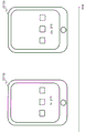
Fig. 1 is a diagram for explaining a procedure of communication between a user and a device using visible light according to embodiment 1.
Fig. 2 is a diagram for explaining a procedure of communication between a user and a device using visible light according to embodiment 1.
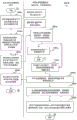
Fig. 3 is a diagram for explaining a procedure from purchase of a device by a user to initial setting of the device according to embodiment 1.
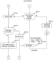
Fig. 4 is a diagram for explaining a service dedicated to a service person in the case of a device failure according to embodiment 1.
Fig. 5 is a diagram for explaining a service for confirming a cleaning status in visual optical communication with a cleaning machine according to embodiment 1.
Fig. 6 is a diagram showing an example of the home environment according to embodiment 2.
Fig. 7 is a diagram showing an example of communication between a home appliance and a smartphone according to embodiment 2.
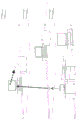
Fig. 8 is a diagram showing an example 1 of the configuration of a transmitting-side apparatus according to embodiment 2.
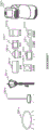
Fig. 9 is a diagram showing an example 1 of the configuration of a receiving side apparatus according to embodiment 2.
Fig. 10 is a diagram showing a flow of a process of transmitting information to a receiving-side apparatus by blinking of an LED of the transmitting-side apparatus in embodiment 2.
Fig. 11 is a diagram showing a flow of a process of transmitting information to a receiving-side apparatus by blinking of an LED of the transmitting-side apparatus in embodiment 2.
Fig. 12 is a diagram showing a flow of a process of transmitting information to a receiving-side apparatus by blinking of an LED of the transmitting-side apparatus in embodiment 2.
Fig. 13 is a diagram showing a flow of a process of transmitting information to a receiving-side apparatus by blinking of an LED of the transmitting-side apparatus in embodiment 2.
Fig. 14 is a diagram showing a flow of a process of transmitting information to a receiving-side apparatus by blinking of an LED of the transmitting-side apparatus in embodiment 2.
Fig. 15 is a schematic diagram of home delivery service support using optical communication according to embodiment 3.
Fig. 16 is a flowchart for explaining home delivery service support using optical communication according to embodiment 3.
Fig. 17 is a flowchart for explaining home delivery service support using optical communication according to embodiment 3.
Fig. 18 is a flowchart for explaining home delivery service support using optical communication according to embodiment 3.
Fig. 19 is a flowchart for explaining home delivery service support using optical communication according to embodiment 3.
Fig. 20 is a flowchart for explaining home delivery service support using optical communication according to embodiment 3.
Fig. 21 is a flowchart for explaining home delivery service support using optical communication according to embodiment 3.
Fig. 22 is a diagram for explaining the process of registering a user and a mobile phone in use with a server according to embodiment 4.
Fig. 23 is a diagram for explaining a process of analyzing user voice characteristics according to embodiment 4.
Fig. 24 is a diagram for explaining the processing for preparing the voice recognition processing according to embodiment 4.
Fig. 25 is a diagram for explaining a process of carrying out sound collection from peripheral sound collecting devices according to embodiment 4.
Fig. 26 is a diagram for explaining the analysis processing of the environmental sound characteristics according to embodiment 4.
Fig. 27 is a diagram for explaining processing of sound from sound output devices present in the periphery in embodiment 4.
Fig. 28 is a diagram for explaining the processing of selecting a cooking menu and setting operation contents to the electric cooker according to embodiment 4.
Fig. 29 is a diagram for explaining the processing of embodiment 4 for acquiring notification sounds for a range from a DB of a server or the like and setting the notification sounds to the range.
Fig. 30 is a diagram for explaining a process of adjusting the notification sound of the electric cooker according to embodiment 4.
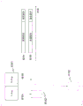
Fig. 31 is a diagram showing an example of a waveform of a notification sound set to a microwave oven according to embodiment 4.
Fig. 32 is a diagram for explaining a process of displaying cooking contents according to embodiment 4.
Fig. 33 is a diagram for explaining the process of recognizing the notification sound of the electric range according to embodiment 4.
Fig. 34 is a diagram for explaining a process of identifying sound collection from peripheral sound collection devices and a cooktop notification sound in embodiment 4.
Fig. 35 is a diagram for explaining a process of notifying a user of the end of operation of the electric cooker according to embodiment 4.
Fig. 36 is a diagram for explaining the process of confirming the operation state of the mobile phone according to embodiment 4.
Fig. 37 is a diagram for explaining the process of tracking the user position according to embodiment 4.
Fig. 38 is a diagram showing recognition of a notification sound of a home appliance while canceling a sound from a sound output device, recognition of a current position of a user (operator) by a communicable electronic device, and notification to the user of a device located closer to the user position based on the recognition result of the user position.
Fig. 39 is a diagram showing the contents of a database held in a server, a mobile phone, or a range according to embodiment 4.
Fig. 40 is a diagram showing the display contents of embodiment 4 in which the user cooks the food based on the cooking procedure displayed on the mobile phone and operates the mobile phone by the sound of "back", "return", and the like.
Fig. 41 is a diagram showing that the user moves to another place during a period such as a period in which the operation of the electric range is started, a period in which the operation is waited for to be ended, or a period in which the user boils east and west in embodiment 4.
Fig. 42 is a diagram showing a command for transmitting a user-finding command from a mobile phone to a device such as a camera, a microphone, or a human body sensor, which is connected to the mobile phone via a network and can recognize the position of the user or recognize the presence of the user.
Fig. 43 is a diagram showing, as an example of detection of a user in embodiment 4, recognition of a user's face by a camera attached to a television and recognition of movement or presence of a user by a human sensor of an air conditioner.
Fig. 44 is a diagram showing a case where the user is detected from the device that has detected the user, and a diagram showing a case where the mobile phone is transmitted from the device that has detected the user to the relative position of the user.
Fig. 45 is a diagram showing the operation end sound of the electric cooker recognized by the mobile phone of embodiment 4.
Fig. 46 is a diagram showing that a command for notifying the user of the operation end of the electric cooker is transmitted to a device having a screen display function or a voice output function among devices in which the user is detected, to the mobile phone which recognizes the operation end of the electric cooker.
Fig. 47 is a diagram showing that the device receiving the command of embodiment 4 notifies the user of the notification content.
Fig. 48 is a diagram showing an operation end sound of a range recognized by a device connected to a mobile phone via a network, provided with a microphone, and present in the vicinity of the range.
Fig. 49 is a diagram showing notification of the end of operation of the electric range to the mobile phone from the device recognizing the end.
Fig. 50 is a diagram showing that when the mobile phone receives a notification of the operation end of the electric range, if the mobile phone is in the vicinity of the user, the user is notified of the operation end of the electric range by using the screen display, the voice output, or the like of the mobile phone.
Fig. 51 is a diagram showing a notification to the user of the end of the operation of the electric cooker.
Fig. 52 is a diagram showing that the user who received the notification of the operation end of the electric cooker moves to the kitchen.
Fig. 53 is a diagram showing transmission of information such as an operation end from the radio communication for the electric range to the mobile phone, notification of a command from the mobile phone to the television being viewed by the user, and notification of the user by a screen display or a sound of the television.
Fig. 54 is a diagram showing a case where information such as an operation end is transmitted from a microwave oven to a television set being watched by a user by wireless communication, and a screen display or a sound of the television set is notified to the user.
Fig. 55 is a diagram showing a screen display or a sound of a television for notifying a user.
Fig. 56 is a diagram showing information notification to a user who is located remotely.
Fig. 57 is a diagram showing transmission of information to a mobile phone via a personal computer or the like when direct communication from a microwave oven to the mobile phone serving as a hub is not possible.
Fig. 58 is a diagram showing information such as an operation command transmitted from the mobile phone receiving the communication of fig. 57 to the electric range along the information communication path in the reverse direction.
Fig. 59 is a diagram showing information notification to the user when direct communication from the air conditioner as the information source device to the mobile phone as the hub is not possible.
Fig. 60 is a diagram for explaining a system using a communication device using radio waves of 700 to 900 MHz.
Fig. 61 is a diagram showing a remote mobile phone notifying a user of information.
Fig. 62 is a diagram showing a remote mobile phone notifying a user of information.
Fig. 63 is a diagram showing a case where, in the same manner as fig. 62, a layer 2 television set functions as a relay device instead of a device that relays the notification identification device and the information notification device.
Fig. 64 is a diagram showing an example of the home environment according to embodiment 5.
Fig. 65 is a diagram showing an example of communication between a home appliance and a smartphone according to embodiment 5.
Fig. 66 is a diagram showing a configuration of a transmitting-side apparatus according to embodiment 5.
Fig. 67 is a diagram showing a configuration of a receiving-side apparatus according to embodiment 5.
Fig. 68 is a sequence diagram in the case where the transmitting side Terminal (TV) and the receiving side terminal (tablet pc) perform wireless LAN authentication using optical communication in fig. 64.
Fig. 69 is a sequence diagram in the case of performing authentication in the application of embodiment 5.
Fig. 70 is a flowchart showing the operation of the transmitting terminal according to embodiment 5.
Fig. 71 is a flowchart showing the operation of the receiving terminal according to embodiment 5.
Fig. 72 is a sequence diagram of data transmission from the mobile AV terminal 1 to the mobile AV terminal 2 according to embodiment 6.
Fig. 73 is a screen transition diagram in the case where the mobile AV terminal 1 according to embodiment 6 transmits data to the mobile AV terminal 2.
Fig. 74 is a screen transition diagram in the case where the mobile AV terminal 1 according to embodiment 6 transmits data to the mobile AV terminal 2.
Fig. 75 is a system schematic diagram in the case where the mobile AV terminal 1 according to embodiment 6 is a digital camera.
Fig. 76 is a system schematic diagram in the case where the mobile AV terminal 1 according to embodiment 6 is a digital camera.
Fig. 77 is a system schematic diagram in the case where the mobile AV terminal 1 according to embodiment 6 is a digital camera.
Fig. 78 is a diagram showing an example of a method for observing the luminance of the light-emitting section according to embodiment 7.
Fig. 79 is a diagram showing an example of a method for observing the luminance of the light-emitting section according to embodiment 7.
Fig. 80 is a diagram showing an example of a method for observing the luminance of the light-emitting section according to embodiment 7.
Fig. 81A is a diagram illustrating an example of a method for observing luminance of the light emitting section according to embodiment 7.
Fig. 81B is a diagram illustrating an example of a method for observing luminance of the light emitting section according to embodiment 7.
Fig. 81C is a diagram illustrating an example of a method for observing the luminance of the light-emitting section according to embodiment 7.
Fig. 81D is a diagram illustrating an example of a method for observing luminance of the light-emitting section according to embodiment 7.
Fig. 81E is a diagram illustrating an example of a method for observing the luminance of the light-emitting section according to embodiment 7.
Fig. 81F is a diagram illustrating an example of a method for observing the luminance of the light-emitting section according to embodiment 7.
Fig. 81G is a diagram illustrating an example of a method for observing luminance of the light-emitting section according to embodiment 7.
Fig. 81H is a diagram illustrating an example of a method for observing luminance of the light-emitting section according to embodiment 7.
Fig. 81I is a diagram illustrating an example of a method for observing luminance of the light emitting section according to embodiment 7.
Fig. 82 is a diagram showing an example of a method for observing the luminance of the light emitting section according to embodiment 7.
Fig. 83 is a diagram showing an example of a signal modulation scheme according to embodiment 7.
Fig. 84 is a diagram showing an example of a signal modulation scheme according to embodiment 7.
Fig. 85 is a diagram showing an example of a signal modulation scheme according to embodiment 7.
Fig. 86 is a diagram showing an example of a signal modulation scheme according to embodiment 7.
Fig. 87 is a diagram showing an example of a signal modulation scheme according to embodiment 7.
Fig. 88 is a diagram showing an example of a signal modulation scheme according to embodiment 7.
Fig. 89 is a diagram showing an example of a signal modulation scheme according to embodiment 7.
Fig. 90 is a diagram showing an example of a signal modulation scheme according to embodiment 7.
Fig. 91 is a diagram showing an example of a signal modulation scheme according to embodiment 7.
Fig. 92 is a diagram showing an example of a signal modulation scheme according to embodiment 7.
Fig. 93 is a diagram showing an example of a signal modulation scheme according to embodiment 7.
Fig. 94 is a diagram showing an example of a signal modulation scheme according to embodiment 7.
Fig. 95 is a diagram showing an example of a signal modulation scheme according to embodiment 7.
Fig. 96 is a diagram showing an example of a signal modulation scheme according to embodiment 7.
Fig. 97 is a diagram showing an example of a signal modulation scheme according to embodiment 7.
Fig. 98 is a diagram showing an example of a signal modulation scheme according to embodiment 7.
Fig. 99 is a diagram showing an example of a detection method of the light-emitting section according to embodiment 7.
Fig. 100 is a diagram showing an example of a detection method of the light-emitting section according to embodiment 7.
Fig. 101 is a diagram illustrating an example of a detection method of the light emitting unit according to embodiment 7.
Fig. 102 is a diagram showing an example of a detection method of the light-emitting unit according to embodiment 7.
Fig. 103 is a diagram showing an example of a detection method of the light-emitting unit according to embodiment 7.
Fig. 104 is a diagram showing time lines of transmission signals and images obtained by imaging the light emitting unit in embodiment 7.
Fig. 105 is a diagram showing an example of signal transmission according to a position pattern in embodiment 7.
Fig. 106 is a diagram showing an example of a receiving apparatus according to embodiment 7.
Fig. 107 is a diagram showing an example of a transmission apparatus according to embodiment 7.
Fig. 108 is a diagram showing an example of a transmission apparatus according to embodiment 7.
Fig. 109 is a diagram showing an example of a transmission apparatus according to embodiment 7.
Fig. 110 is a diagram showing an example of a transmission apparatus according to embodiment 7.
Fig. 111 is a diagram showing an example of a transmission device according to embodiment 7.
Fig. 112 is a diagram showing an example of a transmission apparatus according to embodiment 7.
Fig. 113 is a diagram showing an example of a transmission apparatus according to embodiment 7.
Fig. 114 is a diagram showing an example of a transmission apparatus according to embodiment 7.
Fig. 115 is a diagram showing an example of the structure of the light-emitting section according to embodiment 7.
Fig. 116 is a diagram showing an example of a signal transmission wave according to embodiment 7.
Fig. 117 is a diagram showing an example of an imaging unit according to embodiment 7.
Fig. 118 is a diagram showing an example of estimation of the position of the receiving apparatus according to embodiment 7.
Fig. 119 is a diagram showing an example of estimation of the position of the receiving apparatus according to embodiment 7.
Fig. 120 is a diagram showing an example of estimation of the position of the receiving apparatus according to embodiment 7.
Fig. 121 is a diagram showing an example of estimation of the position of the receiving apparatus according to embodiment 7.
Fig. 122 is a diagram showing an example of estimation of the position of the receiving apparatus according to embodiment 7.
Fig. 123 is a diagram showing an example of setting of transmission information according to embodiment 7.
Fig. 124 is a diagram showing an example of setting of transmission information according to embodiment 7.
Fig. 125 is a diagram showing an example of setting of transmission information according to embodiment 7.
Fig. 126 is a block diagram showing an example of components of the receiving apparatus according to embodiment 7.
Fig. 127 is a block diagram showing an example of components of the transmission device according to embodiment 7.
Fig. 128 is a diagram showing an example of the procedure of reception according to embodiment 7.
Fig. 129 is a diagram showing an example of the procedure of self-position estimation according to embodiment 7.
Fig. 130 is a diagram showing an example of a procedure of transmission control according to embodiment 7.
Fig. 131 is a diagram showing an example of the procedure of transmission control according to embodiment 7.
Fig. 132 is a diagram showing an example of a procedure of transmission control according to embodiment 7.
Fig. 133 is a diagram showing an example of information provision in a station building according to embodiment 7.
Fig. 134 is a diagram showing an example of the riding service according to embodiment 7.
Fig. 135 is a diagram showing an example of the in-store service according to embodiment 7.
Fig. 136 is a diagram showing an example of establishment of a wireless connection according to embodiment 7.
Fig. 137 is a diagram illustrating an example of adjustment of the communication range according to embodiment 7.
Fig. 138 is a diagram showing an example of indoor use in embodiment 7.
Fig. 139 is a diagram showing an example of outdoor use according to embodiment 7.
Fig. 140 is a diagram showing an example of an instruction of a road sequence according to embodiment 7.
Fig. 141 is a diagram showing an example of the use of a plurality of imaging devices according to embodiment 7.
Fig. 142 is a diagram showing an example of autonomous control of the transmission device according to embodiment 7.
Fig. 143 is a diagram showing an example of setting of transmission information according to embodiment 7.
Fig. 144 is a diagram showing an example of setting of transmission information according to embodiment 7.
Fig. 145 is a diagram showing an example of setting of transmission information according to embodiment 7.
Fig. 146 is a diagram showing an example of a combination with a two-dimensional barcode according to embodiment 7.
Fig. 147 is a diagram showing an example of the map creation and use according to embodiment 7.
Fig. 148 is a diagram showing an example of status acquisition and operation of the electronic apparatus according to embodiment 7.
Fig. 149 is a diagram showing an example of identification of the electronic device according to embodiment 7.
Fig. 150 is a diagram showing an example of display of an augmented reality object according to embodiment 7.
Fig. 151 is a diagram showing an example of a user interface according to embodiment 7.
Fig. 152 is a diagram showing an example of a user interface according to embodiment 7.
Fig. 153 is a diagram showing an example of a user interface according to embodiment 7.
Fig. 154 is a diagram showing an example of a user interface according to embodiment 7.
Fig. 155 is a diagram showing an example of a user interface according to embodiment 7.
Fig. 156 is a diagram showing an example of a user interface according to embodiment 7.
Fig. 157 is a diagram showing an example of a user interface according to embodiment 7.
Fig. 158 is a diagram showing an example of a user interface according to embodiment 7.
Fig. 159 is a diagram showing an example of a user interface according to embodiment 7.
Fig. 160 is a diagram showing an example of a user interface according to embodiment 7.
Fig. 161 is a diagram showing an example of a user interface according to embodiment 7.
Fig. 162 is a diagram showing an example of a user interface according to embodiment 7.
Fig. 163 is a diagram showing an example of a user interface according to embodiment 7.
Fig. 164 is a diagram showing an example of a user interface according to embodiment 7.
Fig. 165 is a diagram showing an example of a user interface according to embodiment 7.
Fig. 166 is a diagram showing an example of a user interface according to embodiment 7.
Fig. 167 is a diagram showing an example of a user interface according to embodiment 7.
Fig. 168 is a diagram showing an application example to the ITS of embodiment 8.
Fig. 169 is a diagram showing an application example to the ITS of embodiment 8.
Fig. 170 is a diagram showing an application example of the location information notification system and the facility system according to embodiment 8.
Fig. 171 is a diagram showing an application example of the system to the supermarket according to embodiment 8.
Fig. 172 is a diagram showing an application example of communication between a mobile phone terminal and a camera according to embodiment 8.
Fig. 173 is a diagram showing an application example of communication to water according to embodiment 8.
Fig. 174 is a diagram for explaining an example of service provision to a user according to embodiment 9.
Fig. 175 is a diagram for explaining an example of service provision to a user according to embodiment 9.
Fig. 176 is a flowchart showing a case where the receiver of embodiment 9 simultaneously processes a plurality of signals received from the transmitter.
Fig. 177 is a diagram showing an example of a case where communication between devices is realized by mutual communication according to embodiment 9.
Fig. 178 is a diagram for explaining a service utilizing directivity characteristics according to embodiment 9.
Fig. 179 is a diagram for explaining another example of a service providing example to a user according to embodiment 9.
Fig. 180 is a diagram showing an example of the format of a signal included in a light source emitted from a transmitter according to embodiment 9.
Fig. 181 shows the principle of embodiment 10.
Fig. 182 is a diagram showing an example of the operation of embodiment 10.
Fig. 183 is a diagram showing an example of the operation of embodiment 10.
Fig. 184 is a diagram showing an example of the operation of embodiment 10.
Fig. 185 is a diagram showing an example of the operation of embodiment 10.
Fig. 186A is a diagram showing an example of the operation of embodiment 10.
Fig. 186B is a diagram showing an example of the operation of embodiment 10.
Fig. 186C is a diagram showing an example of the operation of embodiment 10.
Fig. 187 is a diagram illustrating an example of the operation of embodiment 10.
Fig. 188 is a diagram showing an example of the operation of embodiment 10.
Fig. 189 is a diagram showing an example of the operation of embodiment 10.
Fig. 190 is a diagram showing an example of the operation of embodiment 10.
Fig. 191 is a diagram showing an example of the operation of embodiment 10.
Fig. 192 is a diagram showing an example of the operation of embodiment 10.
Fig. 193 is a diagram showing an example of the operation of embodiment 10.
Fig. 194 is a diagram showing an example of the operation of embodiment 10.
Fig. 195 is a timing chart of a transmission signal of the information communication apparatus according to embodiment 11.
Fig. 196 is a diagram showing a relationship between a transmission signal and a reception signal according to embodiment 11.
Fig. 197 is a diagram showing a relationship between a transmission signal and a reception signal according to embodiment 11.
Fig. 198 is a diagram showing a relationship between a transmission signal and a reception signal in embodiment 11.
Fig. 199 is a diagram showing a relationship between a transmission signal and a reception signal according to embodiment 11.
Fig. 200 is a diagram showing a relationship between a transmission signal and a reception signal according to embodiment 11.
Fig. 201 is a diagram showing an application example of a receiver and a transmitter according to embodiment 12.
Fig. 202 is a diagram showing an application example of the receiver and the transmitter according to embodiment 12.
Fig. 203 is a diagram showing an application example of the receiver and the transmitter according to embodiment 12.
Fig. 204 is a diagram showing an application example of the receiver and the transmitter according to embodiment 12.
Fig. 205 is a flowchart showing an example of processing operations of the receiver and the transmitter according to embodiment 12.
Fig. 206 is a diagram showing an application example of the receiver and the transmitter according to embodiment 12.
Fig. 207 is a flowchart showing an example of processing operations of the receiver and the transmitter according to embodiment 12.
Fig. 208 is a diagram showing an application example of the receiver and the transmitter according to embodiment 12.
Fig. 209 is a flowchart showing an example of processing operations of the receiver and the transmitter according to embodiment 12.
Fig. 210 is a diagram showing an application example of the receiver and the transmitter according to embodiment 12.
Fig. 211 is a flowchart showing an example of processing operations of the receiver and the transmitter according to embodiment 12.
Fig. 212 is a diagram showing an application example of the receiver and the transmitter according to embodiment 12.
Fig. 213 is a flowchart showing an example of processing operations of the receiver and the transmitter according to embodiment 12.
Fig. 214 is a diagram showing an application example of the receiver and the transmitter according to embodiment 12.
Fig. 215 is a flowchart showing an example of processing operations of the receiver and the transmitter according to embodiment 12.
Fig. 216 is a diagram showing an application example of the receiver and the transmitter according to embodiment 12.
Fig. 217 is a flowchart showing an example of processing operations of the receiver and the transmitter according to embodiment 12.
Fig. 218 is a diagram showing an application example of the receiver and the transmitter according to embodiment 12.
Fig. 219 is a flowchart showing an example of processing operations of the receiver and the transmitter according to embodiment 12.
Fig. 220 is a diagram showing an application example of the receiver and the transmitter according to embodiment 12.
Fig. 221 is a diagram showing an application example of the receiver and the transmitter according to embodiment 12.
Fig. 222 is a flowchart showing an example of processing operations of the receiver and the transmitter according to embodiment 12.
Fig. 223 is a diagram showing an application example of a receiver and a transmitter according to embodiment 12.
Fig. 224 is a flowchart showing an example of processing operations of the receiver and the transmitter according to embodiment 12.
Fig. 225 is a diagram showing an application example of the receiver and the transmitter according to embodiment 12.
Fig. 226 is a flowchart showing an example of processing operations of the receiver and the transmitter according to embodiment 12.
Fig. 227 is a diagram showing an application example of the receiver and the transmitter according to embodiment 12.
Fig. 228 is a flowchart showing an example of processing operations of the receiver and the transmitter according to embodiment 12.
Fig. 229 is a diagram showing a state of the receiver according to embodiment 12.
Fig. 230 is a flowchart showing an example of the processing operation of the receiver according to embodiment 12.
Fig. 231 is a diagram showing a state of the receiver according to embodiment 12.
Fig. 232 is a flowchart showing an example of processing operation of the receiver according to embodiment 12.
Fig. 233 is a diagram showing a state of the receiver according to embodiment 12.
Fig. 234 is a flowchart showing an example of the processing operation of the receiver according to embodiment 12.
Fig. 235 is a diagram showing a state of the receiver according to embodiment 12.
Fig. 236 is a flowchart showing an example of the processing operation of the receiver according to embodiment 12.
Fig. 237 is a diagram showing a state of the receiver according to embodiment 12.
Fig. 238 is a flowchart showing an example of the processing operation of the receiver according to embodiment 12.
Fig. 239 is a diagram showing an application example of the receiver and the transmitter according to embodiment 12.
Fig. 240 is a diagram showing an application example of the receiver and the transmitter according to embodiment 12.
Fig. 241 is a diagram showing an application example of a receiver and a transmitter according to embodiment 12.
Fig. 242 shows an application example of the receiver and the transmitter according to embodiment 12.
Fig. 243 is a diagram showing an application example of the receiver and the transmitter according to embodiment 12.
Fig. 244 is a diagram showing an application example of the receiver and the transmitter according to embodiment 12.
Fig. 245 is a flowchart showing an example of processing operations of the receiver and the transmitter according to embodiment 12.
Fig. 246 is a flowchart showing an example of processing operations of the receiver and the transmitter according to embodiment 12.
Fig. 247 is a flowchart showing an example of processing operations of the receiver and the transmitter according to embodiment 12.
Fig. 248 is a diagram showing a change in luminance of the transmitter according to embodiment 12.
Fig. 249 is a flowchart showing an example of processing operation of the receiver according to embodiment 12.
Fig. 250 is a diagram showing a change in luminance of the transmitter according to embodiment 12.
Fig. 251 is a flowchart showing an example of the processing operation of the receiver according to embodiment 12.
Fig. 252 is a diagram showing a change in luminance of the transmitter according to embodiment 12.
Fig. 253 is a flowchart showing an example of a processing operation of the transmitter according to embodiment 12.
Fig. 254 is a diagram showing a change in luminance of the transmitter according to embodiment 12.
Fig. 255 is a flowchart showing an example of the processing operation of the receiver according to embodiment 12.
Fig. 256 is a flowchart showing an example of the processing operation of the receiver according to embodiment 12.
Fig. 257 is a flowchart showing an example of processing operation of the transmitter according to embodiment 12.
Fig. 258 is a diagram showing a configuration example of a transmitter according to embodiment 12.
Fig. 259 is a diagram showing a configuration example of a transmitter according to embodiment 12.
Fig. 260 is a diagram showing a configuration example of a transmitter according to embodiment 12.
Fig. 261 is a flowchart showing an example of the processing operation of the receiver according to embodiment 12.
Fig. 262 is a diagram showing an example of display and imaging performed by the receiver and the transmitter according to embodiment 12.
Fig. 263 is a flowchart showing an example of the processing operation of the transmitter according to embodiment 12.
Fig. 264 is a flowchart showing an example of the processing operation of the receiver according to embodiment 12.
Fig. 265 is a diagram showing an application example of the receiver and the transmitter according to embodiment 12.
Fig. 266 is a flowchart showing an example of processing operations of the receiver and the transmitter according to embodiment 12.
Fig. 267 is a diagram showing a state of a receiver according to embodiment 12.
Fig. 268 is a flowchart showing an example of the processing operation of the receiver according to embodiment 12.
Fig. 269 is a diagram showing a state of the receiver according to embodiment 12.
Fig. 270 is a flowchart showing an example of the processing operation of the receiver according to embodiment 12.
Fig. 271 is a flowchart showing an example of the processing operation of the receiver according to embodiment 12.
Fig. 272 is a diagram showing an example of the wavelength of the transmitter according to embodiment 12.
Fig. 273 is a flowchart showing an example of the processing operation of the receiver and the transmitter according to embodiment 12.
Fig. 274 is a diagram showing a configuration example of a system including a receiver and a transmitter according to embodiment 12.
Fig. 275 is a flowchart showing an example of the processing operation of the system according to embodiment 12.
Fig. 276 shows an example of the configuration of a system including a receiver and a transmitter according to embodiment 12.
Fig. 277 is a flowchart illustrating an example of processing operation of the system according to embodiment 12.
Fig. 278 is a flowchart showing an example of the processing operation of the receiver according to embodiment 12.
Fig. 279 is a flowchart showing an example of processing operation of the receiver according to embodiment 12.
Fig. 280 is a diagram showing an example of the configuration of a system including a receiver and a transmitter according to embodiment 12.
Fig. 281 is a flowchart showing an example of a processing operation of the receiver according to embodiment 12.
Fig. 282 is a diagram showing an application example of the receiver and the transmitter according to embodiment 12.
Fig. 283 is a flowchart showing an example of the processing operation of the receiver according to embodiment 12.
Fig. 284 is a diagram showing an example of the configuration of a system including a receiver and a transmitter according to embodiment 12.
Fig. 285 is a flowchart showing an example of processing operation of the system according to embodiment 12.
Fig. 286 is a flowchart showing an example of the processing operation of the receiver according to embodiment 12.
Fig. 287A is a diagram showing an example of the configuration of a transmitter according to embodiment 12.
Fig. 287B is a diagram showing another example of the configuration of the transmitter according to embodiment 12.
Fig. 288 is a flowchart showing an example of processing operations of the receiver and the transmitter according to embodiment 12.
Fig. 289 is a flowchart showing an example of the processing operation of the receiver and the transmitter according to embodiment 13.
Fig. 290 is a flowchart showing an example of processing operations of the receiver and the transmitter according to embodiment 13.
Fig. 291 is a flowchart showing an example of processing operations of the receiver and the transmitter according to embodiment 13.
Fig. 292 is a flowchart showing an example of processing operations of the receiver and the transmitter according to embodiment 13.
Fig. 293 is a flowchart showing an example of processing operations of the receiver and the transmitter according to embodiment 13.
Fig. 294 is a diagram showing an application example of a transmitter according to embodiment 13.
Fig. 295 is a diagram showing an application example of the transmitter according to embodiment 13.
Fig. 296 shows an application example of a transmitter according to embodiment 13.
Fig. 297 is a diagram showing an application example of the transmitter and the receiver according to embodiment 13.
Fig. 298 is a diagram showing an application example of the transmitter and the receiver according to embodiment 13.
Fig. 299 is a diagram showing an application example of the transmitter and the receiver according to embodiment 13.
Fig. 300 is a diagram showing an application example of the transmitter and the receiver according to embodiment 13.
Fig. 301A is a diagram showing an example of a transmission signal according to embodiment 13.
Fig. 301B is a diagram showing another example of the transmission signal according to embodiment 13.
Fig. 302 is a diagram showing an example of a transmission signal according to embodiment 13.
Fig. 303A is a diagram showing an example of a transmission signal according to embodiment 13.
Fig. 303B is a diagram showing another example of the transmission signal according to embodiment 13.
Fig. 304 is a diagram showing an example of a transmission signal according to embodiment 13.
Fig. 305A is a diagram showing an example of a transmission signal according to embodiment 13.
Fig. 305B is a diagram showing an example of a transmission signal according to embodiment 13.
Fig. 306 is a diagram showing an application example of the transmitter according to embodiment 13.
Fig. 307 is a diagram showing an application example of a transmitter according to embodiment 13.
Fig. 308 is a diagram for explaining an image pickup device according to embodiment 13.
Fig. 309 is a diagram for explaining an image pickup device according to embodiment 13.
Fig. 310 is a diagram for explaining an image pickup device according to embodiment 13.
Fig. 311A is a flowchart showing a processing operation of the receiving apparatus (imaging apparatus) according to the modification of each embodiment.
Fig. 311B is a diagram showing a normal imaging mode and a macro imaging mode in comparison in accordance with a modification of each embodiment.
Fig. 312 is a diagram showing a display device for displaying images and the like according to a modification of each embodiment.
Fig. 313 is a diagram showing an example of a processing operation of the display device according to the modified example of each embodiment.
Fig. 314 is a diagram showing an example of a portion of a display device according to a modification of each embodiment, which transmits a signal.
Fig. 315 is a diagram showing another example of the processing operation of the display device according to the modified example of each embodiment.
Fig. 316 is a diagram showing another example of a signal transmission portion of the display device according to the modified example of each embodiment.
Fig. 317 is a diagram showing still another example of the processing operation performed by the display device according to the modified example of each embodiment.
Fig. 318 is a diagram showing a configuration of a communication system including a transmitter and a receiver according to a modification of each embodiment.
Fig. 319 is a flowchart showing a processing operation of the communication system according to the modification of each embodiment.
Fig. 320 is a diagram showing an example of signal transmission according to a modification of each embodiment.
Fig. 321 is a diagram showing an example of signal transmission according to a modification of each embodiment.
Fig. 322 is a diagram showing an example of signal transmission according to a modification of each embodiment.
Fig. 323A is a diagram showing an example of signal transmission according to a modification of each embodiment.
Fig. 323B is a diagram showing an example of signal transmission according to a modification of each embodiment.
Fig. 323C is a diagram showing an example of signal transmission according to a modification of each embodiment.
Fig. 323D is a flowchart showing processing operations of a communication system including a display or a projector and a receiver according to a modification of each embodiment.
Fig. 324 is a diagram showing an example of a transmission signal according to a modification of each embodiment.
Fig. 325 is a diagram showing an example of a transmission signal according to a modification of each embodiment.
Fig. 326 is a diagram showing an example of a transmission signal according to a modification of each embodiment.
Fig. 327A is a diagram showing an example of an image pickup device of a receiver according to a modification of each embodiment.
Fig. 327B is a diagram showing an example of the configuration of an internal circuit of an imaging device of a receiver according to a modification of each embodiment.
Fig. 327C is a diagram showing an example of a transmission signal according to a modification of each embodiment.
Fig. 327D is a diagram showing an example of a transmission signal according to a modification of each embodiment.
Fig. 328A is a diagram for explaining an imaging mode of a receiver according to a modification of each embodiment.
Fig. 328B is a flowchart showing processing operations in the special imaging mode a used in the receiver according to the modified example of each embodiment.
Fig. 329A is a diagram for explaining another imaging mode of the receiver according to the modification of each embodiment.
Fig. 329B is a flowchart showing the processing operation in the special imaging mode B used in the receiver according to the modification of each embodiment.
Fig. 330A is a diagram for explaining still another imaging mode of the receiver according to the modification of each embodiment.
Fig. 330B is a flowchart showing processing operations in the special imaging mode C used in the receiver according to the modified example of each embodiment.
Fig. 331A is a flowchart of an information communication method according to an embodiment of the present invention.
Fig. 331B is a block diagram of an information communication apparatus according to an embodiment of the present invention.
Fig. 331C is a flowchart of an information communication method according to an embodiment of the present invention.
Fig. 331D is a block diagram of an information communication apparatus according to an embodiment of the present invention.
Fig. 332 is a diagram showing an example of an image obtained by an information communication method according to an embodiment of the present invention.
Fig. 333A is a flowchart of an information communication method according to another embodiment of the present invention.
Fig. 333B is a block diagram of an information communication apparatus according to another embodiment of the present invention.
Fig. 334A is a flowchart of an information communication method relating to still another embodiment of the present invention.
Fig. 334B is a block diagram showing an information communication apparatus according to still another embodiment of the present invention.
Fig. 335 is a diagram showing an example of each mode of the receiver according to embodiment 14.
Fig. 336 is a diagram showing an example of the photographing operation of the receiver according to embodiment 14.
Fig. 337 shows another example of the photographing operation of the receiver according to embodiment 14.
Fig. 338A is a diagram showing another example of the photographing operation of the receiver according to embodiment 14.
Fig. 338B is a diagram showing another example of the photographing operation of the receiver according to embodiment 14.
Fig. 338C is a diagram showing another example of the photographing operation of the receiver according to embodiment 14.
Fig. 339A is a diagram showing an example of the camera arrangement of the receiver according to embodiment 14.
Fig. 339B is a diagram showing another example of the camera arrangement of the receiver according to embodiment 14.
Fig. 340 is a diagram showing an example of a display operation of the receiver according to embodiment 14.
Fig. 341 is a diagram showing an example of a display operation of the receiver according to embodiment 14.
Fig. 342 is a diagram showing an example of the operation of the receiver according to embodiment 14.
Fig. 343 is a diagram showing another example of the operation of the receiver according to embodiment 14.
Fig. 344 is a diagram showing another example of the operation of the receiver according to embodiment 14.
Fig. 345 is a diagram showing another example of the operation of the receiver according to embodiment 14.
Fig. 346 shows another example of the operation of the receiver according to embodiment 14.
Fig. 347 is a diagram showing another example of the operation of the receiver according to embodiment 14.
Fig. 348 is a diagram showing another example of the operation of the receiver according to embodiment 14.
Fig. 349 is a diagram showing an example of operations of the receiver, the transmitter, and the server according to embodiment 14.
Fig. 350 is a diagram showing another example of the operation of the receiver according to embodiment 14.
Fig. 351 is a diagram showing another example of the operation of the receiver according to embodiment 14.
Fig. 352 is a diagram showing an example of initial settings of a receiver according to embodiment 14.
Fig. 353 is a diagram showing another example of the operation of the receiver according to embodiment 14.
Fig. 354 is a diagram showing another example of the operation of the receiver according to embodiment 14.
Fig. 355 is a diagram showing another example of the operation of the receiver according to embodiment 14.
Fig. 356 is a diagram showing another example of the operation of the receiver according to embodiment 14.
Fig. 357 is a diagram showing another example of the operation of the receiver according to embodiment 14.
Fig. 358 is a diagram showing another example of the operation of the receiver according to embodiment 14.
Fig. 359A is a diagram showing a pen used for operating the receiver according to embodiment 14.
Fig. 359B is a diagram showing an operation of the receiver using a pen according to embodiment 14.
Fig. 360 is a diagram showing an example of the external appearance of the receiver according to embodiment 14.
Fig. 361 is a diagram showing another example of the external appearance of the receiver according to embodiment 14.
Fig. 362 is a diagram showing another example of the operation of the receiver according to embodiment 14.
Fig. 363A is a diagram showing another example of the operation of the receiver according to embodiment 14.
Fig. 363B is a diagram showing an application example of the receiver according to embodiment 14.
Fig. 364A is a diagram showing another example of the operation of the receiver according to embodiment 14.
Fig. 364B is a diagram showing an application example in which the receiver according to embodiment 14 is used.
Fig. 365A is a diagram showing an example of the operation of the transmitter according to embodiment 14.
Fig. 365B is a diagram showing another example of the operation of the transmitter according to embodiment 14.
Fig. 366 is a diagram showing another example of the operation of the transmitter according to embodiment 14.
Fig. 367 is a diagram showing another example of the operation of the transmitter according to embodiment 14.
Fig. 368 is a diagram showing an example of a communication mode between a plurality of transmitters and a plurality of receivers according to embodiment 14.
Fig. 369 is a diagram showing an example of operations of a plurality of transmitters according to embodiment 14.
Fig. 370 is a diagram showing another example of a communication mode between a plurality of transmitters and receivers according to embodiment 14.
Fig. 371 is a diagram showing another example of the operation of the receiver according to embodiment 14.
Fig. 372 is a diagram showing an application example of the receiver according to embodiment 14.
Fig. 373 is a diagram showing an application example of the receiver according to embodiment 14.
Fig. 374 is a diagram showing an application example of the receiver according to embodiment 14.
Fig. 375 is a diagram showing an application example of the transmitter according to embodiment 14.
Fig. 376 shows an application example of the transmitter according to embodiment 14.
Fig. 377 is a diagram showing an application example of the reception method according to embodiment 14.
Fig. 378 is a diagram showing an application example of the transmitter according to embodiment 14.
Fig. 379 is a diagram showing an application example of the transmitter according to embodiment 14.
Fig. 380 is a diagram showing an application example of the transmitter according to embodiment 14.
Fig. 381 is a diagram showing another example of the operation of the receiver according to embodiment 14.
Fig. 382 is a diagram showing an example of a transmission signal according to embodiment 15.
Fig. 383 is a diagram showing an example of a transmission signal according to embodiment 15.
Fig. 384A is a diagram showing an example of a captured image (bright line image) of the receiver according to embodiment 15.
Fig. 384B is a diagram showing an example of a captured image (bright line image) of the receiver according to embodiment 15.
Fig. 384C is a diagram showing an example of a captured image (bright line image) of the receiver according to embodiment 15.
Fig. 385A is a diagram showing an example of a captured image (bright line image) of the receiver according to embodiment 15.
Fig. 385B is a diagram showing an example of a captured image (bright line image) of the receiver according to embodiment 15.
Fig. 386A is a diagram showing an example of a captured image (bright line image) of the receiver according to embodiment 15.
Fig. 386B is a diagram showing an example of a captured image (bright line image) of the receiver according to embodiment 15.
Fig. 386C is a diagram showing an example of a captured image (bright line image) of the receiver according to embodiment 15.
Fig. 387 is a diagram showing an example of a captured image (bright line image) of the receiver according to embodiment 15.
Fig. 388 is a diagram showing an example of a transmission signal according to embodiment 15.
Fig. 389 is a diagram showing an example of the operation of the receiver according to embodiment 15.
Fig. 390 is a diagram showing an example of an instruction to the user displayed on the screen of the receiver according to embodiment 15.
Fig. 391 is a diagram showing an example of an instruction to the user displayed on the screen of the receiver in embodiment 15.
Fig. 392 is a diagram showing an example of a signal transmission method according to embodiment 15.
Fig. 393 is a diagram showing an example of a signal transmission method according to embodiment 15.
Fig. 394 is a diagram illustrating an example of a signal transmission method according to embodiment 15.
Fig. 395 shows an example of a signal transmission method according to embodiment 15.
Fig. 396 is a diagram illustrating a usage scenario of embodiment 15.
Fig. 397 is a diagram showing an information table transmitted from the smartphone of embodiment 15 to the server.
Fig. 398 is a block diagram of a server according to embodiment 15.
Fig. 399 is a flowchart showing the overall processing of the system according to embodiment 15.
Fig. 400 is a diagram showing an information table transmitted from the server to the smartphone according to embodiment 15.
Fig. 401 is a diagram showing a screen flow displayed on a wearable device from the time when the user of embodiment 15 receives information from a server before the store until the user actually purchases a product.
Fig. 402 is a diagram for explaining another usage scenario in embodiment 15.
Fig. 403 is a diagram showing a service providing system using the reception method described in the above-described embodiment.
Fig. 404 is a flowchart showing the flow of service provision.
Fig. 405 is a flowchart showing another example of service provision. The steps overlapping with those in fig. 404 will not be described.
Fig. 406 is a flowchart showing another example of service provision.
Fig. 407A is a flowchart of an information communication method according to an embodiment of the present invention.
Fig. 407B is a block diagram of an information communication apparatus according to an embodiment of the present invention.
Detailed Description
An information communication method according to an aspect of the present invention is an information communication method for acquiring information from a subject, including: an exposure time setting step of setting an exposure time of the image sensor so that a bright line corresponding to an exposure line included in the image sensor is generated in accordance with a change in luminance of the subject in an image obtained by photographing the subject with the image sensor; a bright line image acquisition step of acquiring a bright line image including the bright line by photographing the subject whose luminance changes with the set exposure time by the image sensor; and an information acquisition step of acquiring information by demodulating data specified by a pattern of the bright line included in the acquired bright line image, wherein the exposure time setting step sets the exposure time to tEAnd setting t as the minimum time unit for brightness change of the objectSIn the case of (1), with tE<tSThe exposure time is set.
In the exposure time setting step, a time difference between start times of adjacent exposure lines of the image sensor may be tDIn the case of (1), with tE+tD<tSThe exposure time is set.
In the exposure time setting step, t may beE≤tSThe exposure time is set in the manner of/2.
Further, an information communication apparatus includes: an exposure time setting unit that sets an exposure time of the image sensor so that, in an image obtained by photographing the subject by the image sensor, bright lines corresponding to exposure lines included in the image sensor are generated in accordance with a change in luminance of the subject; a bright line image acquisition unit that acquires a bright line image including the bright line by photographing the subject whose brightness has changed by the image sensor for the set exposure time; and an information acquisition unit configured to acquire information by demodulating data specified by a pattern of the bright line included in the acquired bright line image, wherein the exposure time setting unit sets the exposure time to tEAnd setting t as the minimum time unit for brightness change of the objectSIn the case of (1), with tE<tSThe exposure time is set.
Further, a computer program for executing an information communication method for acquiring information from a subject, the computer program comprising: an exposure time setting program that sets an exposure time of the image sensor so that a bright line corresponding to an exposure line included in the image sensor is generated in accordance with a change in luminance of the subject in an image obtained by photographing the subject with the image sensor; a bright line image acquisition program for acquiring a bright line image including the bright line by photographing the subject whose brightness has changed by the image sensor for the set exposure time; and an information acquisition program for acquiring information by demodulating data specified by a pattern of the bright line included in the acquired bright line image, wherein the exposure time setting program sets the exposure time to tEAnd setting t as the minimum time unit for brightness change of the objectSIn the case of (1), with tE<tSThe exposure time is set.
Further, a recording medium stores the above-described computer program.
These general and specific technical aspects may be implemented by a system, a method, an integrated circuit, a computer program, a computer-readable recording medium such as a CD-ROM, or any combination of a system, a method, an integrated circuit, a computer program, and a recording medium.
The embodiments are described below in detail with reference to the drawings.
The embodiments described below are all representative of global or specific examples. The numerical values, shapes, materials, constituent elements, arrangement positions and connection forms of the constituent elements, steps, order of the steps, and the like shown in the following embodiments are examples, and do not limit the present invention. Further, among the components of the following embodiments, components that are not recited in the independent claims representing the uppermost concept will be described as arbitrary components.
(embodiment mode 1)
The following describes a flow of processing for transmitting information in a blinking pattern of an LED provided as a device and for camera communication using a smartphone.
Fig. 1 is a diagram showing an example of an environment in a home according to the present embodiment. In the environment shown in fig. 1, the television 1101, the electric cooker 1106, the air cleaner 1107, the smartphone 1105, and the like are also located in the vicinity of the user.
Fig. 2 is a diagram showing an example of communication between the home appliance and the smartphone according to the present embodiment. Fig. 2 is a diagram showing an example of information communication, in which information is obtained by acquiring information output from each device such as the television 1101 or the electric cooker 1106 of fig. 1 by the smartphone 1201 held by the user. As shown in fig. 2, each device transmits information using a blinking pattern of LEDs, and the smartphone 1201 receives information using an imaging function of a camera or the like.
Fig. 3 is a diagram showing an example of the configuration of a transmitting-side apparatus 1301 of the present embodiment.
The transmitting device 1301 transmits information as a light blinking pattern by a user pressing a button, sending a transmission instruction by nfc (near Field communication), or the like, or detecting a change in state such as a failure in the device. At which time the transmission is repeated for a certain time. The shortened ID may be used if the transmitted information is between devices registered in advance. In addition, when a wireless communication unit such as a wireless LAN or a special power saving wireless is provided, authentication information necessary for connection may be transmitted as a blinking pattern.
The transmission rate determining unit 1309 can also perform processing for slowing down the transmission rate when the clock generator is inexpensive and has poor accuracy and speeding up the transmission rate when the clock generator is high, by grasping the performance of the clock generator inside the device. In the case where the performance of the clock generation device is poor, or by dividing the transmitted information itself into shorter ones, it is also possible to reduce errors due to accumulation of variations in the blinking intervals in long-time communication.
Fig. 4 is a diagram showing an example of the configuration of a receiving-side apparatus 1401 according to this embodiment.
The receiving-side apparatus 1401 determines a region where light flicker is visible, based on the frame image acquired by the image acquisition unit 1404. In this case, the flicker may be a method of following a high/low area where a certain or more luminance is observed.
The blinking information acquisition unit 1406 acquires the transmitted information according to the blinking pattern, and when a device including a device ID or the like is associated with the information, the blinking information acquisition unit uses the information to inquire of the associated server on the cloud about the attached information, or uses the device in the wireless communication area stored in advance or the information stored in the receiving-side apparatus to perform interpolation. This can reduce the time required for the user to cover the smartphone with the light-emitting portion of the transmission-side device in order to obtain error correction due to noise when the light emission pattern is imaged, or to obtain already-obtained information.
Fig. 5 is explained below.
Fig. 5 is a diagram showing a flow of a process of transmitting information to a receiving side apparatus such as a smartphone by blinking an LED of the transmitting side apparatus according to the present embodiment. Here, a situation is assumed in which a transmitting side apparatus having a function of communicating with a smartphone by NFC and a light emission pattern of an LED implanted in a part of a communication flag for FC included in the transmitting side apparatus transmit information.
First, in step 1001a, the user purchases the home appliance, and first inserts the power supply into the outlet to set the home appliance in the power-on state.
Next, in step 1001b, it is checked whether or not the initial setting information is written. In the case of yes, proceed to circle 3 in the figure. On the other hand, if no, the process proceeds to step 1001c, where the flag is blinked at a blinking speed (e.g., 1 to 2/5) that is easily understood by the user.
Next, in step 1001d, it is checked whether the user obtains device information of the home appliance by touching the smartphone to the mark through NFC communication. Here, if yes, the process proceeds to step 1001e, and the smartphone receives the device information and registers it with the server of the cloud. Next, in step 1001f, the shortening ID associated with the account of the user of the smartphone is received from the cloud, transmitted to the home appliance, and the process proceeds to step 1001 g. If no in step 1001d, the process proceeds to step 1001 g.
Next, in step 1001g, it is confirmed whether or not there is registration under NFC. If yes, the process proceeds to step 1001j, and after 2 blinks of blue, the blinking ends in step 1001 k.
On the other hand, if no in step 1001g, the process proceeds to step 1001 h. Next, in step 1001h, it is checked whether or not 30 seconds have elapsed. If yes, the process proceeds to step 1001i, and the LED section outputs device information (the model number of the device, the presence or absence of the registration process in NFC, and the unique ID of the device) by blinking light, and proceeds to circle 2 in fig. 6.
If no in step 1001h, the process returns to step 1001 d.
Next, a flow of a process of transmitting information to a receiving side apparatus by blinking of an LED in a transmitting side apparatus according to the present embodiment will be described with reference to fig. 6 to 9. Here, fig. 6 to 9 are diagrams showing a flow of a process of transmitting information to a receiving side apparatus by blinking of an LED of the transmitting side apparatus.
Fig. 6 is explained below.
First, in step 1002a, the user starts an application for acquiring light blinking information of the smartphone.
Next, in step 1002b, the image acquisition unit acquires light flicker. The flicker region determining unit determines a flicker region based on a time-series change in the image.
Next, in step 1002c, the flicker information acquiring unit determines a flicker pattern of the flicker region and waits for preamble detection.
Next, in step 1002d, when the preamble can be detected, information of the blinking region is acquired.
Next, in step 1002e, when the information of the device ID can be acquired, the information is transmitted to the server on the cloud side even in the reception continuation state, and the information interpolation unit interpolates the information acquired from the cloud side while comparing the information with the information of the blinking information acquisition unit.
Next, in step 1002f, if the interpolated information is included and all the information is ready, the information is notified to the smartphone or the user. At this time, by displaying the related site or GUI obtained from the cloud, a rich and easy-to-understand notification can be performed, and the flow proceeds to circle 4 of fig. 7.
Fig. 7 is explained below.
First, in step 1003a, when a home appliance is out of order or a message indicating the number of times of use, room temperature, or the like to the user is generated, the information transmission mode is started.
Next, in step 1003b, the mark is flashed at 1-2/s. At the same time, the LED also starts signaling information.
Next, in step 1003c, it is confirmed whether or not communication under NFC is started. In the case of no, the process proceeds to circle 7 in fig. 9. If yes, the process proceeds to step 1003d, and the blinking of the LED is stopped.
Next, in step 1003e, the smartphone accesses the server in the cloud and displays the related information.
Next, in step 1003f, when a failure to be handled on site is required, a server side searches for a service person for support. The home appliances, the installation place, and the location information are used.
Next, in step 1003g, the service person presses the buttons of the home appliance in a predetermined order to set the home appliance to the support mode.
Next, in step 1003h, when the smartphone sees the blinking of the mark by the LED of the home appliance other than the mark, a part or all of the LEDs that are visible at the same time blink so as to interpolate the information, and the operation proceeds to circle 5 in fig. 8.
Fig. 8 is explained below.
First, in step 1004a, the service person presses the setting button when the performance of the receiving terminal in the possession can detect the blinking at a high speed (for example, 1000/s times).
Next, in step 1004b, the LED of the home appliance blinks in a high-speed mode and advances to the coil 6.
Fig. 9 is explained below.
First, the blinking is continued in step 1005 a.
Next, in step 1005b, the user acquires blinking information of the LED with the smartphone.
Next, in step 1005c, the user activates the application of the smartphone that acquires the light blink information.
Next, in step 1005d, the image acquisition section acquires the flicker of light. The flicker region determining unit determines a flicker region based on a time-series change in the image.
Next, in step 1005e, the flicker information acquiring unit determines the flicker pattern of the flicker region and waits for preamble detection.
Next, in step 1005f, when the preamble can be detected, information of the blinking region is acquired.
Next, in step 1005g, even in the case where the information of the device ID can be acquired, the information is transmitted to the server on the cloud side in the reception continuation state, and the information interpolation unit interpolates the information acquired from the cloud side while comparing the information with the information of the flicker information acquisition unit.
Next, in step 1005h, if the interpolated information is included and all the information is available, the information is notified to the smartphone or the user. In this case, by displaying the related site or GUI obtained from the cloud, it is possible to perform rich and easy-to-understand notification.
Then, step 1003f in fig. 7 is proceeded to.
In this way, the transmitting device such as a home appliance can transmit information to the smartphone by blinking of the LED. Even a device such as a communication device without a wireless function or NFC can transmit information, and a user can be provided with rich information via a smartphone to a server on the cloud.
Further, as in the present embodiment, when a function of transmitting and receiving data by two communication methods of two-way communication (for example, NFC communication) and one-way communication (for example, communication by a change in the brightness of an LED) is provided between two devices including at least one portable device, when data is transmitted from one device to the other device by one-way communication, the one-way communication can be stopped when data transmission and reception are realized by two-way communication. This makes it possible to save the waste of power consumption required for the unidirectional communication, and is therefore efficient.
As described above, according to embodiment 1, it is possible to realize an information communication apparatus capable of performing communication between a variety of devices including devices with weak computation power.
Specifically, the information communication apparatus according to the present embodiment includes an information management unit that manages device information including its own unique ID and device status information, a light emitting element, and a light transmission unit that transmits information as a blinking pattern of the light emitting element, and the light transmission unit converts the device information into a blinking pattern of light and transmits the blinking pattern of light when there is a change in the internal status of the device.
Here, for example, the system may further include a start history management unit that stores information sensed inside the apparatus, such as a start state of the system and a use history of the user, and the light transmission unit may acquire pre-registered performance information of the clock generation device used to change the transmission speed.
For example, the light transmission unit may be configured such that a second light emitting element is arranged around a first light emitting element for transmitting information by blinking of light, and the second light emitting element emits light between the end and the start of information transmission when information transmission by blinking of the first light emitting element is repeated a predetermined number of times.
These global and specific technical aspects may be implemented by a system, a method, an integrated circuit, a computer program, or a recording medium, or may be implemented by any combination of a system, a method, an integrated circuit, a computer program, or a recording medium.
(embodiment mode 2)
In the present embodiment, a description will be given of a communication procedure between a device using visible light communication and a user, and a service cooperation between a repair-supporting service from an initial setting using visible light communication to a failure time and a service using a cleaning machine, taking the cleaning machine as an example.
Fig. 10 and 11 are diagrams for explaining a procedure of performing communication between a user and a device using visible light according to this embodiment.
Fig. 10 will be described below.
First, start in circle 1.
Next, in step 2001a, the user turns on the power.
Next, in step 2001b, it is checked as a start-up process whether or not initial settings such as setting and NW setting are performed.
Here, when the initial setting is made, the process proceeds to step 2001f, and the normal operation is started, and the process ends as indicated by circle 3.
On the other hand, if the initial setting is not performed, the process proceeds to step 2001c, and the user is notified of the necessity of the initial setting by "normal LED emission" or "buzzer sound".
Next, in step 2001d, device information (product number and manufacturing number) is collected, and preparation for visible light communication is performed.
Next, in step 2001e, the user is notified of the device information (product number and manufacturing number) and the possibility of visible light communication by "LED communication light emission", "icon display to display", "buzzer sound", and "a plurality of LEDs light emission".
And ends as indicated by circle 2.
Next, fig. 11 will be explained.
First, it starts as indicated by circle 2.
Next, in step 2002a, the proximity sensor, the illuminance sensor, and the human detection sensor sense the proximity of the visible light receiving terminal.
Next, in step 2002b, visible light communication is started with the sensed condition as a trigger event.
Next, in step 2002c, the user acquires device information using the visible light receiving terminal.
Then, the process ends as indicated by the circle 4. Alternatively, the process proceeds to any of step 2002f to step 2002 i.
When the process proceeds to step 2002f, the lighting of the device information is stopped when the lighting of the room is sensed by the sensing of the "sensitivity sensor" and the "cooperation with the light control device", and the lighting is terminated as shown by circle 5. Further, when the process proceeds to step 2002g, the visible light receiving terminal acquires device information, notifies the sensed information by "NFC communication" and "NW communication", and ends the notification. When the process proceeds to step 2002h, the separation of the visible light receiving terminal is sensed, and the device information is stopped and ended. When the process proceeds to step 2002i, the light emission of the device information is stopped and ended after waiting for a lapse of a certain time.
If the user does not perceive it in step 2002a, the process proceeds to step 2002d, and the notification that the visible light communication is possible is highlighted and notified by "brighten", "make sound louder", or "move icon" after a certain time has elapsed. Here, the procedure returns to step 2002 d. Alternatively, the process proceeds to step 2002e, and further proceeds to step 2002i after a certain time elapses.
Fig. 12 is a diagram for explaining a procedure until a user purchases a device and performs initial setting of the device according to the present embodiment.
In fig. 12, the process starts as indicated by circle 4.
Next, in step 2003a, the position information of the smartphone, which has received the device information, is acquired by using gps (global Positioning system).
Next, in step 2003b, if there is user information in the smartphone, user information such as a user name, a telephone number, a mail address, and the like is collected in the terminal. Alternatively, in step 2003c, if there is no user information in the smartphone, the user information is collected from the peripheral device through the NW.
Next, in step 2003d, the device information, the user information, and the location information are transmitted to the cloud server.
Next, in step 2003e, information required for initial setting and activation information are collected using the device information and the position information.
Next, in step 2003f, information on IP, authentication method, available service, and the like necessary for setting in cooperation with the device registered by the user is collected. Alternatively, in step 2003g, the device information and the setting information are transmitted to the device registered by the user via the NW, whereby the cooperation setting with the peripheral device is performed.
Next, in step 2003h, user setting is performed using the device information and the user information.
Next, in step 2003i, the initial setting information, the activity information, and the cooperation setting information are transmitted to the smartphone.
Next, in step 2003j, the initial setting information, the activation information, and the cooperation setting information are transmitted to the home appliance by NFC.
Next, in step 2003k, device setting is performed by the initial setting information, the activation information, and the cooperation setting information.
And ends as indicated by circle 6.
Fig. 13 is a diagram for explaining a service dedicated to a service person in the case of a device failure according to the present embodiment.
In fig. 13, the process starts as indicated by circle 3.
Next, in step 2004a, history information such as an operation log and a user operation log generated during normal operation of the device is recorded in the local storage medium.
Next, in step 2004b, error information such as an error code and details of the error is recorded together with the occurrence of the failure, and the LED abnormal light emission notification is performed to notify that the visible light communication is possible.
Next, in step 2004c, the LED high-speed light emission mode is set by the special command execution of the service person, and the high-speed communication of the visible light is started.
Next, in step 2004d, it is determined whether the terminal in proximity is a normal smartphone or a dedicated receiving terminal for a service person. Here, when the process proceeds to step 2004e, the error information is acquired and the process ends in the case of the smartphone.
On the other hand, when the process proceeds to step 2004f, the service person acquires error information and history information by using a dedicated reception terminal.
Next, in step 2004g, the device information, the error information, and the history information are transmitted to the cloud, and the repair method is acquired. Here, when the process proceeds to step 2004h, the LED high-speed emission mode is released and ended by a special command of the service person.
On the other hand, when the process proceeds to step 2004i, the related product of the device information, the product information of the similar product, the selling price of the nearest store, and the new product information are acquired from the cloud server.
Next, in step 2004j, user information is acquired by visible light communication using a smartphone of the user and a dedicated terminal of a service person, and a product is ordered to the nearest store via the cloud server.
And ends as indicated by circle 9.
Fig. 14 is a diagram for explaining a service for confirming a cleaning status, which uses visible light communication with a cleaning machine according to the present embodiment.
First, it starts as indicated by circle 3.
Next, in step 2005a, cleaning information in a normal operation of the apparatus is recorded.
Next, in step 2005b, the room layout information is combined to create the dirt information, and the dirt information is encrypted and compressed.
Here, in the case of proceeding to step 2005c, the dirt information is recorded to the local storage medium with compression of the dirt information as a trigger. Alternatively, when the process proceeds to step 2005d, the dirt information is transmitted to the lighting apparatus by visible light communication using the suspension of cleaning (stop of suction processing) as a trigger. Alternatively, when the process proceeds to step 2005e, the recording of the dirt information is used as a trigger, and the dirt information is transmitted to the home local server and the cloud server by the NW.
Next, in step 2005f, the device information, the storage location, and the decryption key are transmitted to the smartphone through visible light communication, with the transmission and recording of the dirty information as a trigger event.
Next, in step 2005g, the NW and the NFC acquire and decode the fouling information.
And ends as indicated by circle 10.
As described above, according to embodiment 2, it is possible to realize a visible light communication system including an information communication device capable of performing communication between a variety of devices including devices with weak computation power.
Specifically, the visible light communication system (fig. 10) including the information communication device according to the present embodiment is equipped with a visible light transmission availability determining unit for determining whether or not preparation for visible light transmission is completed, and a visible light transmission notifying unit for notifying the user that visible light transmission is being performed, and notifies the user visually and audibly when the state is a visible light communication enabled state. Thus, the user can be more convenient by notifying the user of the status of visible light reception by setting the light emission pattern of the LED to "light emission color", "sound", "icon display", and "multi-LED light emission".
As described with reference to fig. 11, the visible light communication system may preferably be one in which a terminal approach sensing unit that senses the approach of the visible light receiving terminal and a visible light transmission determining unit that determines the start and stop of visible light transmission based on the position of the visible light receiving terminal are mounted, and the visible light transmission is started with the terminal approach sensing unit sensing the approach of the visible light receiving terminal as a trigger event.
Here, for example, as described in fig. 11, the visible light communication system may be configured to stop the transmission of the visible light by using the terminal approach sensing unit to sense the detachment of the visible light receiving terminal as a trigger event. As described in fig. 11, for example, a visible light communication system may be provided with a peripheral illuminance sensing unit that senses the lighting-out of a room, and the visible light transmission may be stopped using the lighting-out of the room sensed by the peripheral illuminance sensing unit as a trigger. Accordingly, by sensing the approach and departure of the visible light receiving terminal and the lighting-off of the room, the visible light communication is started only in a state where the visible light communication is possible, and thus unnecessary visible light communication can be omitted to achieve energy saving.
Further, as described in fig. 11, for example, a visible light communication system may be provided with a visible light communication time monitoring unit that measures the time during which visible light is transmitted and a visible light transmission notification unit that notifies the user that visible light is being transmitted, and the visual and auditory notifications to the user may be further enhanced by using as a trigger event that the visible light communication is performed more than or equal to a certain amount but the visible light receiving terminal is not approaching. As described in fig. 11, for example, the visible light transmission may be stopped by using a case where the visible light transmission notification unit performs the enhanced notification and the visible light transmission time is not longer than a certain time but the visible light receiving terminal is not in the proximity as a trigger event.
Thus, when the visible light transmission time is longer than a certain time but the reception is not performed by the user, the reception of the visible light to the user is stopped, and the user forgets to receive or cancel the reception, thereby improving the convenience of the user.
The visible light communication system (fig. 12) including the information communication device according to the present embodiment may be a visible light communication system including a visible light reception determination unit configured to determine reception of visible light communication, a reception terminal position acquisition unit configured to acquire a terminal position, and a device setting information collection unit configured to acquire device information and position information and collect device setting information, and acquire a position of the reception terminal when receiving visible light as a trigger event, and collect information necessary for device setting. Accordingly, the device information acquired by the visible light communication is used as the trigger event, the device setting is automatically collected, and the position information and the user information required for the user registration are set, so that the input and the registration procedure performed by the user are omitted, and the convenience can be improved.
Here, as described with reference to fig. 14, the visible light communication system may be configured to include an apparatus information management unit configured to manage apparatus information, an apparatus relationship management unit configured to manage similarity between an apparatus and an apparatus, a store information management unit configured to manage store information of a sales apparatus, and a most recent store search unit configured to search for a most recent store based on location information, and to acquire the most recent store and a price for selling a similar apparatus using received apparatus information and location information as trigger events. Thus, according to the sales status of the equipment and the sales shop associated with the equipment information collection, the convenience of the user can be improved by omitting the time and effort for searching for the equipment.
The visible light communication system (fig. 12) including the information communication apparatus according to the present embodiment may be a visible light communication system including a user information monitoring unit that monitors a state in which user information is stored in a terminal, a user information collecting unit that collects user information from a peripheral device via an NW, and a user registration processing unit that acquires user information and device information and performs user registration, and may collect user information from an accessible peripheral device and perform user registration together with the device information, using absence of user information as a trigger event. Accordingly, the device information acquired by the visible light communication is used as a trigger event, the device setting is automatically collected, and the position information and the user information required for the user registration are set, so that the input and the registration procedure by the user are omitted, and the convenience can be improved.
The visible light communication system (fig. 13) including the information communication device according to the present embodiment may be a visible light communication system including a command determination unit that receives a special command, a visible light communication frequency, and a visible light communication speed adjustment unit that operates a plurality of LEDs in cooperation, and the visible light communication may be speeded up by adjusting the visible light communication frequency and the number of LEDs to be transmitted by receiving the special command. Here, for example, as described with reference to fig. 14, the visible light communication system may be provided with a terminal type determination unit that determines the type of the proximity terminal by NFC communication and a transmission information type determination unit that determines the type of the transmitted information based on the terminal type, and the amount of information transmitted by the proximity terminal and the visible light communication speed may be changed. Thus, by adjusting the frequency and the number of transmission LEDs of the visible light communication and changing the speed and the transmission information of the visible light communication according to the receiving terminal, high-speed communication can be performed, and user convenience can be improved.
The visible light communication system (fig. 14) including the information communication device according to the present embodiment may be a visible light communication system including a cleaning information recording unit that records cleaning information, a room layout information recording unit that records room layout information, an information synthesizing unit that generates dirt part information by superimposing the room layout information and the cleaning information, and an operation monitoring unit that monitors the stop of a normal operation, and may send the dirt part information to the outside visually by using the detection of the stop of the apparatus as a trigger event.
These global and specific technical aspects may be implemented by a system, a method, an integrated circuit, a computer program, or a recording medium, or may be implemented by any combination of a system, a method, an integrated circuit, a computer program, or a recording medium.
(embodiment mode 3)
In the present embodiment, the cooperation between Web information and devices using optical communication will be described, taking a home delivery service as an example.
Fig. 15 shows an outline of the present embodiment. That is, fig. 15 is a schematic diagram of home delivery service support using optical communication according to the present embodiment.
Specifically, the orderer orders the product from the product purchase site using the mobile terminal 3001 a. Upon completion of the order, an order number is issued from the merchandise purchase site. The mobile terminal 3001a that has received the order number transmits the order number to the door access phone home device 3001b using NFC communication.
The door access telephone home device 3001b displays the order number received from the mobile terminal 3001a on a monitor of the device, and presents a transmission completion message to the user.
The door phone home device 3001b transmits a blinking instruction and a blinking pattern of an LED built in the door phone home device 3001c to the door phone home device 3001 c. The blinking pattern is generated by the door access telephone home device 3001b based on the order number received from the mobile terminal 3001 a.
The door phone outdoor device 3001c blinks the LED according to a blinking pattern specified from the door phone outdoor device 3001 b.
Instead of the mobile terminal, an environment such as a PC that can be accessed to a commodity purchase site located at WWW3001d may be used.
As a transmission mechanism from the portable terminal 3001a to the door phone home device 3001b, a home network may be used in addition to NFC communication.
The mobile terminal 3001a may transmit the order number directly to the door phone device 3001c without passing through the door phone device 3001 b.
When the home delivery order reception server 3001e receives the order number from the home delivery order mobile terminal 3001f, the home delivery order reception server 3001e transmits the order number to the home delivery person mobile terminal. When the home delivery person reaches the home delivery destination, optical communication using the LED blinking pattern generated based on the order number is performed in both directions of the home delivery person mobile terminal 3001f and the door phone outdoor unit 3001 c.
Next, description will be given with reference to fig. 16 to 21. Fig. 16 to 21 are flowcharts for explaining home delivery service support using optical communication according to embodiment 3 of the present invention.
Fig. 16 shows a flow from when the subscriber places an order to when the subscriber issues an order number. Fig. 16 will be described below.
In step 3002a, subscriber mobile terminal 3001a makes a reservation for home delivery using a Web browser or an application of a smartphone. Then, the process advances to circle 1 of fig. 17.
Next, circle 2 of fig. 17 is followed, and in step 3002b, the subscriber mobile terminal 3001a stands by in a subscription number transmission waiting state. Next, in step 3002c, it is confirmed whether or not contact is made on the order number transmission destination device. If yes, the process proceeds to step 3002d, where the entrance phone is brought into NFC contact with the indoor unit to transmit the order number (there is a method of transmitting the order number via the network even if the entrance phone exists in the same network as the smartphone). On the other hand, if no, the process returns to step 3002 b.
The door phone home device 3001b first waits for a request for LED blinking from another terminal in step 3002 e. Next, in step 3002f, a subscription number is received from the smartphone. Next, in step 3002g, an LED flashing instruction of the outdoor unit of the door phone is issued according to the received order number. Then, the process advances to circle 3 of fig. 19.
First, in step 3002h, the door phone external device 3001c waits for an LED flashing instruction from the door phone internal device. Then, the process advances to circle 7 of fig. 19.
The home distributor mobile terminal 3001f stands by in an order notification waiting state in step 3002 i. Next, in step 3002j, it is confirmed whether or not the order notification is notified from the home delivery order server. Here, if no, the process returns to step 3002 i. If yes, the process proceeds to step 3002k, and information such as the order number and the home delivery destination address is received. Next, in step 3002n, the user stands by until he/she has an LED lighting instruction of the received order number or starts the camera for LED lighting recognition of another device. Then, the process advances to circle 5 of fig. 18.
Fig. 17 shows a flow until the subscriber places a home delivery order using the subscriber mobile terminal 3001 a. Fig. 17 will be described below.
The home delivery subscription server 3001e first waits for the acceptance of the subscription number in step 3003 a. Next, it is confirmed in step 3003b whether the home delivery order is received. If no, the process returns to step 3003 a. If yes, the process proceeds to step 3003c, and the received home delivery order is issued with an order number. Next, in step 3003d, the home delivery person is notified of the reception of the home delivery order and the process ends.
Next to circle 1 of fig. 16, the subscriber mobile terminal 3001a selects subscription content from a menu presented by the home delivery subscription server in step 3003 e. Next, in step 3003f, the order is determined and sent to the home delivery server. Next, in step 3003g, it is confirmed whether or not the order number is received. Here, if no, the process returns to step 3003 f. If yes, the process proceeds to step 3003h, where the received order number is displayed, and a display is performed to prompt contact with the door phone home. Then, the process advances to circle 2 of fig. 16.
Fig. 18 shows a flow of optical communication between the home delivery person and the door phone outdoor unit 3001c of the home delivery destination by using the home delivery person mobile terminal 3001 f. Fig. 18 will be described below.
Next to circle 5 of fig. 16, the home delivery person mobile terminal 3001f confirms whether or not the camera is activated in order to recognize the LED of the door phone outdoor unit 3001c of the home delivery destination in step 3004 a. If no, the routine returns to circle 5 in fig. 16.
On the other hand, if yes, the process proceeds to step 3004b, where the camera of the home delivery person mobile terminal confirms that the LED of the home delivery destination door phone outdoor unit is blinking.
Next, in step 3004c, the LED of the door phone outdoor unit is identified to emit light and is compared with the order number.
Next, in step 3004d, it is checked whether or not the LED blinking of the door phone outdoor unit matches the order number. Here, in the case of yes, the procedure advances to circle 6 of fig. 20.
In the case of no, it is checked whether or not the other LEDs can be checked to blink in the camera. If yes, the process returns to step 3004c, and if no, the process ends.
Fig. 19 shows a flow of matching the order number between the door phone home device 3001b and the door phone home device 3001 c. Fig. 19 will be described below.
Next to circle 7 of fig. 16, the door phone outdoor unit 3001c confirms whether or not there is an instruction of LED blinking from the door phone indoor unit in step 3005 a. If not, the routine returns to the circle of fig. 16. If yes, the process proceeds to step 3005b, where the LED is flashed in accordance with the LED flash instructed from the door phone home apparatus. And, advances to circle 8 of fig. 20.
Next to circle 9 of fig. 20, in step 3005c, the door phone outdoor unit 3001c notifies the door phone indoor unit of an LED flash recognized by the camera of the door phone outdoor unit. Then, the process advances to circle 10 of fig. 21.
Next to circle 3 of fig. 16, the door phone homemaker 3001c instructs the door phone homemaker to blink on and off an LED corresponding to the order number in step 3005 d. Next, in step 3005e, the system stands by until the camera of the door phone outdoor unit recognizes that the LED of the home delivery person mobile terminal blinks. Next, in step 3005f, it is checked whether or not the LED flicker is recognized from the door phone outdoor unit. Here, if no, the process returns to step 3005 e. If yes, the LED of the door phone outdoor unit is blinked with the order number in step 3005 g. Next, in step 3005h, it is checked whether or not the LED blinking of the door phone outdoor unit matches the order number. In the case of yes, the procedure advances to the circle 11 in fig. 21. On the other hand, if no, the LED blinking suspension is instructed to the entrance phone outdoor unit in step 3005i, and the process ends.
Fig. 20 shows a flow between the door access telephone out-home device 3001c and the home delivery person mobile terminal 3001f after the order number comparison. Fig. 20 will be described below.
Following circle 6 of fig. 18, the home distributor mobile terminal 3001f starts LED blinking in accordance with the order number held by the home distributor mobile terminal in step 3006 a.
Next, in step 3006b, the LED blinking part is arranged in a range where the image can be taken from the door phone house device camera.
Next, in step 3006c, it is checked whether or not the LED of the home delivery person mobile terminal photographed by the camera of the door phone outdoor unit is blinking and matches the order number held by the door phone outdoor unit, and whether or not the blinking of the LED of the door phone outdoor unit indicates matching.
Here, if no, the process returns to step 3006 b. On the other hand, if yes, the process proceeds to step 3006e, and the home distributor mobile terminal displays whether or not the two match, and ends.
Further, as shown in fig. 20, the door phone outdoor unit 3001c follows circle 8 of fig. 19, and confirms whether or not the LED of the home delivery person mobile terminal is turned on by the camera of the door phone outdoor unit in step 3006 f. Here, in the case of yes, the procedure advances to circle 9 in fig. 19. If not, the routine returns to the circle in fig. 19.
Fig. 21 shows a flow between the door access telephone out-home device 3001c and the home delivery person mobile terminal 3001f after the order number comparison. Fig. 21 will be described below.
Following circle 11 of fig. 19, the door phone-home device 3001c confirms whether or not a notification is given in step 3007a as to whether or not the LED blinking notification of the door phone-home device matches the order number. If no, the routine returns to circle 11 in fig. 19. On the other hand, if yes, the process proceeds to step 3007b, and the gate phone outdoor unit blinks the LED indicating whether or not the signals match.
Further, as shown in fig. 21, following circle 10 of fig. 19, the door phone home device 3001b calls up an indication that the delivery person has arrived at the home phone, and notifies the subscriber of the arrival by sound output in step 3007 c. Next, in step 3007d, the outside device of the entrance telephone is instructed to blink on the LED indicating that the blinking stoppage of the LED blinking coincides with the order number. And then ends.
In addition, when the home delivery destination is not present in the apartment, a home delivery box for storing the home delivery object may be installed in an entrance or the like. When a subscriber is absent at the time of home delivery, the home delivery person stores the home delivery item in the home delivery box. Alternatively, the door phone outdoor unit 3001c may automatically use only the house delivery box corresponding to the size of the house delivery object by optically communicating the camera of the door phone outdoor unit 3001c with the LED of the house delivery person mobile terminal 3001f and transmitting the size of the house delivery object.
As described above, according to embodiment 3, it is possible to realize cooperation of Web information and devices using optical communication.
(embodiment mode 4)
(registering user and mobile phone in use with Server)
Fig. 22 is a diagram for explaining a process of registering a user and a mobile phone in use with the server according to the present embodiment. Fig. 22 is explained below.
First, in step 4001b, the user launches the application.
Next, in step 4001c, the information of the user and the mobile phone is collated with each other to the server.
Next, in step 4001d, it is checked whether or not the user information and the information of the mobile phone in use are registered in the DB of the server.
If so, the process proceeds to step 4001f, and analysis of the user voice characteristics is started (process a) as parallel processing, and the process proceeds to B in fig. 24.
On the other hand, if no, the flow proceeds to 4001e, the mobile phone ID and the user ID are registered in the mobile phone table of DB, and the flow proceeds to B in fig. 24.
(Process a: analysis of user Sound characteristics)
Fig. 23 is a diagram for explaining the process of analyzing the user voice characteristics according to the present embodiment. Fig. 23 is explained below.
First, in step 4002a, sound is collected from the microphone.
Next, in step 4002b, it is checked whether or not the sound collection sound is estimated as the user's sound as a result of the sound recognition. Here, if no, the process returns to step 4002 a.
If yes, the process proceeds to step 4002c to check whether the occurrence content is a key used in the application ("back", "return", etc.). If so, the process proceeds to step 4002f, the voice data is registered in the user key voice table of the server, and the process proceeds to step 4002 d. On the other hand, if no, the process proceeds to step 4002 d.
Next, in step 4002d, the sound characteristics (frequency, sound pressure, speech rate) are analyzed.
Next, in step 4002e, the analysis result is registered in the user voice characteristics table of the mobile phone and the server.
(preparation of Voice recognition processing)
Fig. 24 is a diagram for explaining the processing for preparing the voice recognition processing according to the present embodiment. Fig. 24 is explained below.
First, in step 4003a, following B in the figure, an operation of displaying a cooking menu list is performed (by a user operation).
Next, in step 4003b, a list of cooking menus is obtained from the server.
Next, in step 4003c, a cooking menu list is displayed on the portable device screen.
Next, in step 4004d, sound collection is started from a microphone connected to the mobile phone.
Next, in step 4003e, sound collection from peripheral sound collecting devices is started (process b) as parallel processing.
Next, in step 4003f, analysis of the ambient sound characteristics is started (processing c) as parallel processing.
Next, in step 4003g, cancellation of sound from sound output devices present in the periphery is started (process d) as parallel processing.
Next, in step 4003h, the user voice characteristics are acquired from the DB of the server.
Finally, in step 4003i, recognition of the user voice is started, and the process proceeds to C in fig. 28.
(processing b: Sound Collection from surrounding Sound Collection devices)
Fig. 25 is a diagram for explaining a process of sound collection from the sound collecting devices around the present embodiment. Fig. 25 is explained below.
First, in step 4004a, a device (sound collecting device) that can communicate with the mobile phone and can collect sound is searched.
Next, in step 4004b, it is confirmed whether or not a sound collecting device is found.
Here, the process ends in the case of no. If so, the process proceeds to step 4004c, where the position information and the microphone characteristic information of the sound collector are acquired from the server.
Next, in step 4004d, it is checked whether information exists in the server.
If yes, the process proceeds to step 4004e to check whether the installation position of the sound collecting device is sufficiently close to the position of the mobile phone to collect the sound of the user. If no in step 4004e, the process returns to step 4004 a. On the other hand, if yes in step 4004e, the process proceeds to step 4004f to start sound collection by the sound collection device. Next, in step 4004g, the sound collected by the sound collecting device is transmitted to the mobile phone until there is a command to end the sound collecting process. Further, the sound collected may not be transmitted to the mobile phone as it is, but the result of the voice recognition may be transmitted to the mobile phone. The sound transmitted to the mobile device is processed in the same manner as the sound collected from the microphone connected to the mobile phone, and the process returns to step 4004 a.
If no in step 4004d, the process proceeds to step 4004h to start sound collection by the sound collection device. Next, in step 4004i, a signal tone is output from the mobile phone. Next, in step 4004j, the sound collected by the sound collecting device is transmitted to the mobile phone. Next, in step 4004k, it is checked whether or not a signal sound can be recognized from the sound transmitted from the sound collecting device. If yes, the process proceeds to step 4004g, and if no, the process returns to step 4004 a.
(Process c: analysis of environmental Sound characteristics)
Fig. 26 is a diagram for explaining the analysis processing of the environmental sound characteristic according to the present embodiment. Fig. 26 is explained below.
First, in step 4005f, a list of devices other than those whose positions are sufficiently distant from the position of the electric range, among the devices owned by the user, is retrieved. Data of sounds emitted from these devices is acquired from the DB.
Next, in step 4005g, characteristics (frequency, sound pressure, and the like) of the acquired sound data are analyzed and held as environmental sound characteristics. In addition, since the sound of a rice cooking machine or the like near the electric range is particularly likely to be recognized by mistake, a high degree of importance is set and maintained.
Next, in step 4005a, sound is collected from the microphone.
Next, in step 4005b, it is checked whether or not the sound collected is the sound of the user, and if so, the routine returns to step 4005 a. If not, the process proceeds to step 4005c, where characteristics (frequency and sound pressure) of the sound collected are analyzed.
Next, in step 4005d, the ambient sound characteristic is updated based on the analysis result.
Next, in step 4005e, it is checked whether the end flag is on, and if so, the process ends. If no, the flow returns to step 4005 a.
(Process d: canceling sound from sound output devices existing in the periphery)
Fig. 27 is a diagram for explaining the processing of the present embodiment for canceling sound from sound output devices present in the periphery. Fig. 27 is explained below.
First, in step 4006a, a device capable of communication and a device capable of sound output (sound output device) are searched.
Next, in step 4006b, it is checked whether or not the audio output device is found, and if not, the process ends. If so, the process proceeds to step 4006c, where the audio output device is caused to output a signal sound including various frequencies.
Next, in step 4006d, sound collection is performed by the mobile phone and the sound collection device (each sound collection device) shown in fig. 25, and the signal sound output from the sound output device is collected.
Next, in step 4006e, it is checked whether or not the tone can be collected and recognized, and if not, the process ends. If so, the process proceeds to step 4006f, where the transmission characteristics (the relationship between the output volume of each frequency and the sound collection volume, and the delay time from the signal sound output to the sound collection) from the sound output device to each sound collection device are analyzed.
Next, in step 4006g, it is checked whether or not the sound data output from the sound output device is accessible from the mobile phone.
Here, if yes, the process proceeds to step 4006h, and before a command to end the cancellation process is issued, the sound source, the output location, and the volume output from the sound output device are acquired, and the sound output from the sound output device is cancelled from the sounds collected by the sound collection devices, taking into account the transmission characteristics. Returning to step 4006 a. On the other hand, if no, the process proceeds to step 4006i, and before a command to end the cancellation process is issued, the sound output from the sound output device is acquired, the sound output from the sound output device is cancelled from the sound collected by each sound collecting device while considering the transmission characteristics, and the process returns to step 4006 a.
(cooking menu selection and operation content setting to electric cooker)
Fig. 28 is a diagram for explaining the processing of selecting a cooking menu and setting operation contents to the electric cooker according to the present embodiment. Fig. 28 is explained below.
First, next to C in the figure, in step 4007a, a menu to be cooked is selected (by a user operation).
Next, in step 4007b, recipe parameters (cooking amount, taste concentration, heating level, etc.) are set (user operation).
Next, in step 4007c, recipe data corresponding to the recipe parameter is acquired from the server, and a cooking range operation content setting command is issued.
Next, in step 4007d, the user is prompted to touch the cellular phone to a non-contact IC tag implanted in the electric range.
Next, in step 4007e, it is confirmed whether contact to the electric cooker is detected.
Here, if no, the flow returns to step 4007 e. If so, the process proceeds to step 4007f, and the electric cooker setting command acquired from the server is transmitted to the electric cooker. Accordingly, all the settings of the electric range necessary for the cooking method are performed, and the user can cook the food by simply pressing the operation start button of the electric range.
Next, in step 4007g, (process e) a notification sound for the electric range is acquired from the DB of the server or the like, and is set to the electric range.
Next, in step 4007h, (process f) the notification sound of the electric cooker is adjusted, and the process proceeds to D in fig. 32.
(Process e: obtaining notification sound for electric cooker from DB of server, etc.; setting to electric cooker)
Fig. 29 is a diagram for explaining the processing of acquiring a notification sound for a range from a DB such as a server and setting the notification sound to the range according to the present embodiment. Fig. 29 is explained below.
First, in step 4008a, the user brings the mobile phone close to (i.e., in contact with) a non-contact IC tag implanted in an electric range.
Next, in step 4008b, the electric range is inquired whether notification sound data for the mobile phone (data of a sound output at the time of operating or ending the electric range) is registered in the electric range.
Next, in step 4008c, it is checked whether notification sound data for the mobile phone is registered in the electric range.
Here, the process ends in the case of yes. If not, the process proceeds to step 4008d to check whether notification sound data for the mobile phone is registered in the mobile device. If yes, the flow proceeds to step 4008h, and the notification sound data registered in the mobile phone is registered in the electric range and the operation ends. On the other hand, if no, the process proceeds to step 4008e, and the DB of the server, the mobile phone, or the electric range is referred to.
Next, in step 4008f, if there is notification sound data for the mobile phone (data of a notification sound that is easily recognized by the mobile phone) in the DB, the data is acquired from the DB, and if there is no notification sound data for a general mobile phone (data of a notification sound that is easily recognized by a general mobile phone) is acquired from the DB.
Next, in step 4008g, the acquired notification sound data is registered in the mobile phone.
Next, in step 4008h, the notification sound data registered in the mobile phone is registered with the electric range and ended.
(processing f: adjustment of notification tone of electric cooker)
Fig. 30 is a diagram for explaining a process of adjusting the notification sound of the electric cooker according to the present embodiment. Fig. 30 is explained below.
First, in step 4009a, notification sound data of the electric range registered in the mobile phone is acquired.
Next, in step 4009b, it is checked whether or not the frequency of the notification sound for the terminal overlaps with the frequency of the ambient sound by a predetermined value or more.
Here, the process ends in the case of no.
On the other hand, if yes, the process proceeds to step 4009c, where the volume of the notification sound is set to a sufficiently larger volume than the ambient sound. Or the frequency of the notification sound is changed.
Here, if the cooking range can output the sound of (c) in fig. 31, the cooking range is finished by creating the notification sound in the style of (c), as an example of the method of creating the notification sound with the changed frequency. If (c) is not able but (b) is able, a notification sound is generated in the style of (b) and the process is ended. If only (a) is possible, a notification sound is produced in the pattern of (a) and the process is terminated.
Fig. 31 is a diagram showing an example of a waveform of a notification sound set to a microwave oven according to the present embodiment.
The waveform shown in fig. 31(a) is a simple rectangular wave, and can be output by almost all audio output devices. Since it is easily confused with sounds other than the notification sound, the notification sound is outputted several times, and if some of them can be recognized, a correspondence should be made to recognize that the notification sound sounds or the like.
The waveform shown in fig. 31(b) is a waveform obtained by finely dividing the waveform of (a) by a short-time rectangular wave, and can be output if the operation clock of the audio output device is sufficiently fast. This sound can be heard in the human ear similarly to the sound (a), but in mechanical recognition, the amount of information is larger than that of (a), and it is difficult to confuse with sounds other than the notification sound.
The waveform shown in fig. 31(c) is a waveform in which the length of time of the sound output portion is changed, and is referred to as a PWM waveform. The information is difficult to output than (b), but the amount of information is larger than (b), and the information to be transmitted can be transmitted from the electric range to the mobile phone at the same time with an improved recognition rate.
Although the waveforms in fig. 31(b) and 31(c) are less likely to be misrecognized than in fig. 31(a), the recognition rate can be further improved by repeating the same waveform a plurality of times as in fig. 31 (a).
(display of cooking Contents)
Fig. 32 is a diagram showing an example of a waveform of a notification sound set to a microwave oven according to the present embodiment. Fig. 32 is explained below.
First, following D in the figure, in step 4011a, the cooking contents are displayed.
Next, in step 4011b, it is checked whether the cooking content is the operation of the electric cooker.
Here, if yes, the process proceeds to step 4011c, and the user is notified that ingredients are loaded into the electric range and presses the operation start button, and proceeds to fig. 33E.
On the other hand, if no, the process proceeds to step 4011d, the cooking content is displayed, and the process proceeds to F in the figure or proceeds to step 4011 e.
In step 4011e, it is confirmed what the operation by the user is. And ends in the case where the application ends.
On the other hand, when the display content is changed, the user performs a manual input (such as a button press), or a voice input ("backward", "forward", or the like), the process proceeds to step 4011f, and it is checked whether or not the cooking is completed as a result of the change of the display content. If yes, the process proceeds to step 4011g, and the end of cooking is notified to the user and ended. If no, the process proceeds to step 4011 a.
(recognition of the Notification tone of electric cooker)
Fig. 33 is a diagram for explaining the process of recognizing the notification sound of the electric cooker according to the present embodiment. Fig. 33 is explained below.
First, following E in the figure, in step 4012a, as parallel processing, (process g) recognition of sound collection from peripheral sound collection devices and a focus notification sound is started.
Next, in step 4012f, as parallel processing, (process i) confirmation of the operation state of the mobile phone is started.
Next, in step 4012g, as parallel processing, (process j) tracking of the user position is started.
Next, in step 4012b, the identification content is confirmed.
If the notification sound of the button press is recognized, the routine proceeds to step 4012c, changes the registration setting, and returns to step 4012 b. If the user operation is recognized, the flow proceeds to F in fig. 32. When it is recognized (a notification sound of the end of the operation or a sound of opening the door of the electric range) after the operation time has elapsed since the food is loaded into the electric range and the operation start button is pressed, the user is notified of the end of the operation of the electric range in step 4012e, and the process proceeds to step G of fig. 32. When the notification sound of the start of the operation is recognized, the routine proceeds to step 4012d, waits until the operation time elapses, proceeds to step 4012e, and (process h) notifies the user of the end of the operation of the electric cooker, and proceeds to step G of fig. 32.
(Process g: recognition of collecting tone from peripheral sound collecting devices and cooker notification tone)
Fig. 34 is a diagram for explaining a process of recognizing sound collection and a cooktop notification sound from peripheral sound collection devices according to the present embodiment. Fig. 34 is explained below.
First, in step 4013a, a device (sound collecting device) capable of communicating with a mobile phone and collecting sound is searched.
Next, in step 4013b, it is confirmed whether or not a sound collecting device is found.
Here, the process ends in the case of no. On the other hand, if yes, the process proceeds to step 4013c, and position information and microphone characteristic information of the sound collector are acquired from the server.
Next, in step 4013d, it is confirmed whether or not information exists in the server.
If yes, the process proceeds to step 4013r to check whether the installation position of the sound collecting device is sufficiently close to the microwave oven to collect the notification sound.
If no in step 4013r, the procedure returns to step 4013 a. If so, the process proceeds to step 4013s to check whether or not the arithmetic device of the sound collecting apparatus can perform voice recognition. If yes in step 4013s, information for identifying a notification sound of a cooking stove is transmitted to a sound collecting device in step 4013 u. Next, in step 4013v, the sound collecting device is caused to start sound collection and sound recognition, and the recognition result is transmitted to the mobile phone. Next, in step 4013q, before proceeding to the next cooking stage, recognition processing of a notification sound of the electric cooker is performed, and the recognition result is transmitted to the mobile phone. On the other hand, if no in step 4013s, the process proceeds to step 4013t, where the sound collecting device starts sound collection and transmits the sound collection sound to the mobile phone. Next, in step 4013j, before proceeding to the next cooking stage, a sound collection sound is transmitted to the mobile phone, and the mobile phone recognizes a notification sound of the electric cooker.
If no in step 4013d, the process proceeds to step 4013e, and it is checked whether or not the arithmetic device of the sound collecting equipment can perform voice recognition.
If yes, the process proceeds to step 4013k, and information for identifying a notification sound of the electric cooker is transmitted to the sound collecting device. Next, in step 4013m, the sound collecting device is caused to start sound collection and sound recognition, and the recognition result is transmitted to the mobile phone. Next, in step 4013n, a notification sound of the electric cooker is sounded. Next, in step 4013p, it is checked whether the notification sound can be recognized by the sound collecting device. If yes in step 4013p, the process proceeds to step 4013q, a recognition process of a notification sound of the microwave oven is performed before proceeding to the next cooking stage, and the recognition result is transmitted to the mobile phone and returned to step 4013 a. If no in step 4013p, the procedure returns to step 4013 a.
If no in step 4013e, the process proceeds to step 4013f, where the sound collecting device starts sound collection and transmits the sound collection sound to the mobile phone. Next, in step 4013g, a notification sound of the electric cooker is sounded. Next, in step 4013h, a recognition process is performed on the voice transmitted from the sound collecting device. Next, in step 4013i, it is checked whether the notification sound can be recognized. If yes, the process proceeds to 4013j, and before proceeding to the next cooking stage, the sound collecting sound is transmitted to the mobile phone, and the mobile phone recognizes the notification sound of the electric cooker and returns to step 4013 a. In the case of no, the process returns to step 4013 a.
(processing h: informing the user of the end of the operation of the electric cooker)
Fig. 35 is a diagram for explaining the process of notifying the user of the end of the operation of the electric cooker according to the present embodiment. Fig. 35 is explained below.
First, in step 4013a, it is checked whether it can be determined that the mobile phone is being used or determined that the mobile phone is moving based on sensor data. If yes, the process proceeds to step 4014m, and the user is notified of the end of the operation of the electric cooker using a screen display of the mobile phone, sound, vibration, or the like, and then the operation is ended.
On the other hand, if no in step 4013a, the process proceeds to step 4014b, and a device under operation (user-operated device) such as a PC logged in by the user is searched for.
Next, in step 4014c, it is confirmed whether or not the user-operating device is found. In addition, in the case of yes, the end of the operation of the electric cooker is notified to the user using a screen display of the device being operated by the user or the like.
On the other hand, if no in step 4014c, the process proceeds to step 4014e, and a device (imaging device) capable of communicating with the mobile phone and acquiring an image is searched for.
Next, in step 4014f, it is confirmed whether or not the image pickup apparatus is found.
Here, if yes, the process proceeds to step 4014p, where the image pickup apparatus is caused to pick up an image, the face data of the user is transmitted to the image pickup apparatus, and the user's face is recognized. Alternatively, the captured image is transmitted to a mobile phone or a server, and the user's face is recognized as the image transmission destination.
Next, in step 4014q, it is checked whether the face of the user is recognized. In the case of no, return is made to step 4014 e. If yes, the process proceeds to step 4014r to check whether or not there is a display device or a sound generating device in the device (discovery device) in which the user is found. If yes in step 4014r, the process proceeds to step 4014s, and the operation end of the electric cooker is notified to the user using a device attached to the equipment and ended.
If no in step 4014f, the process proceeds to step 4014g, and a device (sound collecting device) capable of communicating with the mobile phone and collecting sound is searched for.
If no in step 4014h, the process proceeds to step 4014i, and a device capable of specifying the user's position by a method such as operation of another device or walking vibration is found. Next, the process proceeds to step 4014m, and the operation end of the electric cooker is notified to the user by using a screen display, sound, vibration, or the like of the mobile phone, and the operation is ended.
If yes in step 4014i, the process proceeds to step 4014r, and it is checked whether or not there is a display device or a sound generating device in the device (discovery device) in which the user is found. If no, the process proceeds to step 4014t, and location information of the discovered device is acquired from the server.
Next, in step 4014u, a device (notification device) having a display device or a sound generation device in the vicinity of the discovery device is searched for. Next, in step 4014v, the user is notified of the end of the operation of the electric cooker by a screen display or a sound of a sufficient volume in consideration of the distance from the notification device to the user, and the operation is ended.
(processing i: confirmation of operating state of cellular phone)
Fig. 36 is a diagram for explaining the process of confirming the operation state of the mobile phone according to the present embodiment. Fig. 36 is explained below.
First, in step 4015a, it is confirmed whether the user is operating the mobile phone, moving the mobile phone, inputting/outputting to/from an input/output device connected to the mobile phone, playing video or music, operating a device located closer to the mobile phone, or being recognized by a camera or various sensors of the device located closer to the mobile phone.
If yes, the process proceeds to step 4015b, and the probability that the location identified as the user is closer to the mobile phone is high, and the process returns to step 4015 a.
On the other hand, if no, the process proceeds to step 4015c, where it is confirmed whether or not a device located far from the mobile phone is operating, a camera or various sensors of the device located far from the mobile phone recognize the user, or charging is underway.
If yes in step 4015c, the process proceeds to step 4015d, and the probability that the location identified as the user is farther from the mobile phone is high, and the process returns to step 4015 a. In step 4015c, if no, the process returns to step 4015 a.
(Process j: tracking of user position)
Fig. 37 is a diagram for explaining the process of tracking the user position according to the present embodiment. Fig. 37 is explained below.
First, in step 4016a, it is checked whether the mobile phone is determined to be moved by the direction sensor, the position sensor, or the 9-axis sensor. The 9-axis sensor is a sensor including at least 1 of an acceleration sensor, an angular velocity sensor, and a geomagnetic sensor.
If yes in step 4016a, the process proceeds to step 4016b, where the locations of the mobile phone and the user are registered in the DB, and the process returns to step 4016 a.
On the other hand, if no in step 4016a, the process proceeds to step 4016c, and a device (user detection device) capable of detecting the position of the user or the presence of the user, such as a mobile phone communication device, a camera, a microphone, or a human body sensor, is searched for.
Next, in step 4016d, it is confirmed whether or not a sound collecting device is found. If no in step 4016d, the procedure returns to step 4016 a.
If yes in step 4016d, the flow proceeds to step 4016e to determine whether the user is detected by the user detection device. If no in step 4016e, the procedure returns to step 4016 a.
If yes in step 4016e, the process proceeds to step 4016f, and the user's knowledge is transmitted to the mobile phone.
Next, in step 4016g, a case where the user is present in the vicinity of the user-ascertained device is registered with the DB.
Next, in step 4016h, if the user ascertains the location information of the device in the DB, the location of the user is determined, and the process returns to step 4016 a.
Fig. 38 is a diagram showing recognition of a notification sound of a home appliance while canceling a sound from a sound output device, recognition of a current position of a user (operator) by a communicable electronic device, and notification to the user of a device located closer to the user position according to the recognition result of the user position. Fig. 39 is a diagram showing the contents of a database held in a server, a mobile phone, or a range according to the present embodiment.
As shown in fig. 39, a range table 4040a associates and holds the range model, data (speaker characteristics, modulation scheme, and the like) for specifying the sound that can be output, data having a notification sound that is easily recognized by the mobile phone according to the various mobile phone models, and notification sound data that is easily recognized by a general mobile phone on average.
In the mobile device table 4040b, the individual mobile phone, the model of the mobile phone, the user using the mobile phone, and data indicating the position of the mobile phone are associated and held.
In the mobile device model table 4040c, the model of the mobile phone is associated with and held in association with sound collection characteristics of a microphone or the like attached to the mobile phone model.
In the user sound characteristic table 4040d, the sound characteristics of the user and the sound of the user are held in association with each other.
In the user keyword sound table 4040e, sound waveform data of a user when the user utters a keyword to be recognized by the mobile phone such as "go back" or "return" is held in association with the user. The data may be not the audio waveform data itself, but may be analyzed and transformed into a format that is easy to handle.
In the user-owned device location table 4040f, the user, the device owned by the user, and the location data of the device are held in association with each other.
In the user-owned device location table 4040g, data of sounds such as notification sounds and operation sounds generated by the user, the device owned by the user, and the device are held in association with each other.
In the user position table 4040h, data of the positions of the user and the user are stored in association with each other.
Fig. 40 is a diagram showing the display contents of the mobile phone which is cooked by the user based on the cooking procedure displayed on the mobile phone and operated by the user by the voices such as "back" and "return". Fig. 41 is a diagram showing that the user moves to another place during the time such as the period of starting the operation of the electric range, waiting for the end of the operation, or cooking east and west in the present embodiment. Fig. 42 is a diagram showing a command for transmitting a user-finding command from a mobile phone to a device such as a camera, a microphone, or a human body sensor, which is connected to the mobile phone via a network and can recognize the position of the user or recognize the presence of the user. Fig. 43 shows a diagram in which a camera attached to a television recognizes a user's face and a motion sensor of an air conditioner recognizes the movement or presence of the user, as an example of user detection. The identification process may be performed by a television or an air conditioner, or the image data or the like may be transmitted to a mobile phone or a server, and the identification process may be performed by a transmission destination. However, from the viewpoint of privacy protection, the user data should not be transmitted to an external server.
Fig. 44 is a diagram showing a case where a search is sent from a device which has searched for a user to a mobile phone, and a relative position from the searched device to the user.
In this way, if there is location information in the DB that ascertains the user's device, the user's location can be determined.
Fig. 45 is a diagram showing the operation end sound of the portable telephone of the present embodiment recognizing the electric range. Fig. 46 is a diagram showing that the mobile phone recognizing the operation end of the electric cooker transmits a command for notifying the user of the operation end of the electric cooker to the device having the screen display function or the sound output function (in this figure, the television set located on the front side of the user) among the devices which have been detected by the user.
Fig. 47 is a diagram showing that the device which has received the above-described command notifies the user of the notification content (in this figure, the operation end of the electric cooker is displayed on the screen of the television). Fig. 48 is a diagram showing an operation end sound of a device connected to a mobile phone via a network, provided with a microphone, and existing in the vicinity of a microwave oven recognizing the microwave oven. Fig. 49 is a diagram showing a notification to the mobile phone from the device recognizing the end of the operation of the electric range. Fig. 50 is a diagram showing that when the mobile phone receives a notification of the operation end of the electric range, if the mobile phone is in the vicinity of the user, the operation end of the electric range is notified to the user by using the screen display or the sound output of the mobile phone.
Fig. 51 is a diagram showing a user being notified of the end of the operation of the electric cooker. Specifically, fig. 51 is a diagram showing that when the mobile phone receives a notification of the operation end of the electric range, if the mobile phone is not near the user, a command for notifying the user of the operation end of the electric range is transmitted to a device having a screen display function or a sound output function (a television set on the front side of the user in the present figure) among devices of the user, and the device receiving the command notifies the user of the operation end of the electric range. This shows that when a mobile phone is connected to a charger, the mobile phone does not exist near a range or near a user in many cases, and the situation shown in the figure is likely to occur.
Fig. 52 is a diagram showing that the user who received the notification of the operation end of the electric cooker moves to the kitchen. At this time, the mobile phone displays the next cooking content. The mobile phone may recognize that the user has moved to the kitchen by voice or the like, and start the following description of the cooking procedure at a proper timing.
Fig. 53 is a diagram showing that information such as the end of operation is transmitted from the electric range to the mobile phone by wireless communication, a notification command is given from the mobile phone to the television set being viewed by the user, and notification is given to the user by the screen display or sound of the television set.
Further, communication between the information source device (in this figure, a range) and the mobile phone, and communication between the mobile phone and the device (in this figure, a television) that notifies the user may use an in-home LAN, direct wireless communication, in particular, wireless communication of 700MHz to 900MHz stations, or the like. Here, the mobile phone is used as a hub, but other devices having a communication capability may be used instead of the mobile phone.
Fig. 54 shows that information such as the end of operation is transmitted from the electric cooker to the television set being watched by the user by wireless communication, and the user is notified by using the screen display or sound of the television set. It shows an operation without going through the mobile phone which plays a role as a hinge in fig. 53.
Fig. 55 is a diagram showing that, when the air conditioner of layer 1 notifies information, information is transmitted to the air conditioner of layer 2, information is transmitted from the air conditioner of layer 2 to the mobile phone, a notification command is given from the mobile phone to the television set viewed by the user, and the user is notified by the screen display or sound of the television set. It is indicated that, when direct communication from an information source device (air conditioner of layer 1 in the present figure) to a mobile phone serving as a hub is not possible, information is transmitted to another device capable of communication, and communication to the mobile phone is performed.
Fig. 56 is a diagram showing information notification to a user who is located remotely. Specifically, fig. 56 shows information notification to a remote user through internet or carrier communication from a mobile phone that receives notification from a power station via voice, light, wireless communication, or the like. Fig. 57 is a diagram showing transmission of information to a mobile phone via a personal computer or the like when direct communication from a microwave oven to the mobile phone serving as a hub is not possible. Fig. 58 is a diagram showing information such as an operation command transmitted from the mobile phone receiving the communication of fig. 57 to the electric range along the information communication path in the reverse direction.
The mobile phone may receive the information shown in fig. 57 and automatically transmit the information, or may notify the user of the information and transmit information of an operation performed by the user upon receiving the notification.
Fig. 59 is a diagram showing information notification to the user when direct communication from the air conditioner as the information source device to the mobile phone as the hub is not possible. Specifically, fig. 59 shows that, when direct communication cannot be performed from an air conditioner as an information source device to a mobile phone as a hub, first, information is transmitted from a personal computer or the like as a device of a ladder for communication to the mobile phone in circle 1, information is transmitted from the personal computer to the mobile phone through the internet or a carrier communication network in circles 2 and 3, the mobile phone automatically processes the information, or an operation of a user holding the mobile phone is received, information is transmitted to the personal computer through the internet or a carrier communication network in circles 4 and 5, a notification command is transmitted from the personal computer to a device (a television in the figure) that can notify the user of the information in circle 6, and information is notified to the user using a screen display of the television or a voice in circle 7.
Such a situation is likely to occur when the user who should receive the notification information from the air conditioner is different from the user who is using the mobile phone.
In the present figure, the communication between the personal computer and the mobile phone is performed via the internet or a carrier communication network, but the communication may be performed by an in-home LAN, direct communication, or the like.
FIG. 60 is a diagram for explaining a system using a communication device using radio waves of 700 to 900 MHz. Specifically, in the configuration of fig. 60, a system using a communication device (hereinafter, referred to as a G device) using a radio wave of 700 to 900MHz (hereinafter, referred to as a G radio wave) will be described, which shows that information is transmitted from a range with a G device to a mobile phone with a layer 3 of the G device using a G radio wave, information is transmitted from a mobile phone with a layer 3 of the G device to a mobile phone with a layer 2 of the G device without using a home network, and information is notified from the mobile phone with a layer 2 to a user.
Further, a method of using FC belonging to both devices for registration and authentication of communication between devices with G devices is conceivable. In addition, when NFC is not provided in any device, a method may be considered in which the output of the G radio wave is reduced as a registration mode so that communication is possible only at a distance of about 10 to 20cm, and communication between G devices is registered and authenticated when both devices are brought close to each other and communication is successful.
Note that the information source device (in this figure, a range) may be a device other than a range as long as it includes the G device.
Note that, as long as a device (in the present figure, a layer-3 cellular phone) that relays an information source device and an information notifying device (in the present figure, a layer-2 cellular phone) can access a G-wave and a home network, the device may be a device such as a personal computer, an air conditioner, or a smart meter, instead of the cellular phone.
The information notification device may be a device such as a personal computer or a television set, instead of a mobile phone, as long as it can access the home network and can notify the user of the information by using a screen display, an audio output, or the like.
Fig. 61 is a diagram showing a remote mobile phone notifying a user of information. Specifically, fig. 61 shows transmission of information from an air conditioner with a G device to a mobile phone with a G device in a home, transmission of information from the mobile phone in the home to a remote mobile phone via the internet or a carrier communication network, and notification of information to a user with the remote mobile phone.
The information source device (air conditioner in this figure) may be a device other than a cooking range as long as it includes the G device.
Note that, as long as the device (in the present figure, the home-use mobile phone) that relays the information source device and the information notifying device (in the present figure, the remote mobile phone) can access the G-wave, the internet, or the carrier communication network, the device may be a device such as a personal computer, an air conditioner, or a smart meter, instead of the mobile phone.
The information notifying apparatus may be a personal computer, a television set, or the like, instead of the mobile phone, as long as it can access the internet or the carrier communication network and can notify the user of the information by using a screen display, a voice output, or the like.
Fig. 62 is a diagram showing a remote mobile phone notifying a user of information. Specifically, fig. 62 shows that the television with G device recognizes the notification sound of the electric range without G device, the television transmits information to the mobile phone in the home with G device via G radio wave, transmits information from the mobile phone in the home to the mobile phone in the remote via the internet or carrier communication network, and the mobile phone in the remote notifies the user of the information.
Note that the same applies to the information source device (in this figure, a range) if it is another device, and the same applies to the method of notifying the identification device (in this figure, a television) of identifying the notification of the information source device if it is not a sound but a light-emitting state.
Note that the notification identification device is also similar to other devices with G devices. Note that, a device (in the present figure, a mobile phone in a home) that relays the notification recognition device and the information notification device (in the present figure, a remote mobile phone) may be a device such as a personal computer, an air conditioner, or a smart meter, instead of the mobile phone, as long as the device can access the G-wave, the internet, or the carrier communication network.
The information notifying apparatus may be a personal computer, a television set, or the like, instead of the mobile phone, as long as it can access the internet or the carrier communication network and can notify the user of the information by using a screen display, a voice output, or the like.
Fig. 63 is a diagram similar to fig. 62, in which a 2-tier television set functions as a relay device instead of a device (in fig. 62, a mobile phone in a home) that relays a notification identification device (in this figure, a 2-tier television set) and an information notification device (in this figure, a remote mobile phone).
As described above, the apparatus according to the present embodiment realizes the following functions.
Function of learning user's voice characteristics by utilization of application
Function of finding a sound collecting device capable of collecting sound emitted from a mobile phone, among devices capable of communicating with the mobile phone and having a sound collecting function
Function of finding a sound collecting device capable of collecting sound emitted from an electronic device, among devices having a sound collecting function and capable of communicating with a mobile phone
Function of transmitting the sound collected by the sound collecting device to the mobile phone as it is or the result of sound recognition
Function of analyzing characteristics of environmental sound and improving accuracy of sound recognition
Function of acquiring from DB a voice that can be output from a device owned by a user, and improving accuracy of voice recognition
Function of finding, in a device having a sound collecting function and capable of communicating with a mobile phone, a sound output device capable of collecting sound emitted from the mobile phone or the sound collecting device
A function of acquiring sound data output from the sound output device, subtracting sound data from sound collection sound in consideration of transmission characteristics, and removing unnecessary sound data from sound collection sound
A function of receiving input of parameters of a cooking recipe, obtaining a cooking order instructed to a user from a server, and controlling data for controlling a cooking apparatus
Function of setting notification sound emitted from device based on sound that can be output from device, so as to make portable telephone or sound collecting device easily recognize
Function for improving recognition accuracy of user voice by adjusting recognition function based on voice characteristics of user
Function of recognizing user's voice using a plurality of sound collecting devices
Function of recognizing notification sound of electronic device using a plurality of sound collecting devices
Functions for obtaining necessary information from the electronic device and setting the electric range by one operation through the mobile phone and the non-contact IC card of the electronic device, etc., to perform a series of operations
Functions of searching for a user using a device capable of detecting a user, such as a camera, a microphone, or a human body sensor, in a device capable of communicating with a mobile phone, transmitting the current position of the user to the mobile phone, or storing the current position in the DB
Function of notifying user from device existing nearby using user location saved in DB
Function for estimating presence/absence of user in the vicinity of mobile phone based on state (operation state, sensor value, charge state, data link state, etc.) of mobile phone
In the processing in fig. 22 to 52, the same function can be achieved if the sound data is read as light emission data (frequency, brightness, or the like), the sound output is read as light emission, and the sound collection is read as light reception.
In the present embodiment, an electric range is taken as an example, but if an electronic device that emits a notification sound for identification is not an electric range, the electronic device can be changed to a washing machine, a rice cooker, a cleaner, a refrigerator, an air cleaner, a hot water bottle, a dish washer-dryer, an air conditioner, a personal computer, a mobile phone, a television, an automobile, a telephone, a mail receiving device, or the like, and the same effects can be obtained.
In the present embodiment, devices such as a range, a mobile phone, and a television that notify a user directly communicate with each other, but when there is a problem in direct communication, communication may be performed indirectly via another device.
In the present embodiment, communication mainly using a home LAN is assumed, but the same function can be achieved if the communication is performed via direct wireless communication between devices or communication via the internet or a carrier communication network.
In the present embodiment, the user's location is encrypted and transmitted to the own mobile phone by making a query from the mobile phone at a glance or by recognizing a person with a camera of a TV or the like, and therefore leakage of personal information is prevented. When there are a plurality of people at home, the position of the operator can be estimated by placing data of human detection sensors of an air conditioner, an air cleaner, and a refrigerator in a position management database of a portable device or the like and tracking the operator with the movement sensor following the operator once recognized.
In addition, when the user holds a mobile phone having a gyroscope or an azimuth meter, the specified position data may be registered in the user position database.
Further, when the operator places the portable device, first, since the motion of the physical sensor is stationary for a certain period of time, this situation can be detected. When the user leaves the home appliance, a human sensor or a button operation using a home appliance or a lighting fixture, a camera such as a TV, a microphone of a mobile device, or the like is used. Then, the location is registered in a user location database of a server in the mobile device or home.
As described above, according to embodiment 4, an information communication apparatus (identification apparatus) capable of performing communication between devices can be realized.
Specifically, the information communication apparatus according to the present embodiment may include a recognition device for searching for an electronic device (sound collecting device) having a sound collecting function among electronic devices communicable from the operation terminal, and recognizing a notification sound of another electronic device by using the sound collecting function of the sound collecting device.
Here, the identification means may be identification means using a sound collecting function of a sound collecting device capable of collecting only a signal sound emitted from the operation terminal.
The information communication apparatus according to the present embodiment may include an electronic device (sound collecting device) that searches for an electronic device capable of communicating with an operation terminal and has a sound collecting function, a sound collecting device that analyzes sound transmission characteristics between the sound output device and the sound collecting device to obtain output sound data of the sound output device, and removes sound output from the sound output device from sound collecting sound based on the sound transmission characteristics and the output sound data.
The information communication apparatus according to the present embodiment may further include a recognition device for adjusting the notification sound of the electronic device that desires to recognize the notification sound so as not to be buried in the environmental sound.
The information communication apparatus according to the present embodiment may be an information communication apparatus that stores electronic equipment owned by a user (owned electronic equipment), data of sound output from the owned electronic equipment, and position data of the owned electronic equipment in a database, and includes a recognition unit that adjusts the notification sound of the electronic equipment to be recognized so as to easily distinguish between the sound output from the owned electronic equipment and the notification sound of the electronic equipment to be recognized.
Here, the recognition means may be a recognition means for adjusting the voice recognition processing so as to easily distinguish between the voice output from the electronic device and the notification sound of the electronic device which wants to recognize the notification sound.
The information communication device according to the present embodiment may include an identification device for identifying whether the operation terminal is close to the operator by using the operation state of the operation terminal, the sensor value of the physical sensor, the data link state, and the charging state.
Here, the identification means may be an identification means for identifying the position of the user by using an operation state of the electronic device communicable from the operation terminal, a camera, a microphone, a human motion sensor, and position data of the electronic device held in the database.
The identification device may be included in an information notification device that notifies a user of information using an electronic device (notification device) having a function capable of notifying the user by means of screen display, audio output, or the like, which is held in a database, using the identification result of the user's position.
These global and specific technical aspects may be implemented by a system, a method, an integrated circuit, a computer program, or a recording medium, or may be implemented by any combination of a system, a method, an integrated circuit, a computer program, or a recording medium.
(embodiment 5)
Currently, various simple authentication methods are studied in wireless communication. For example, a WPS of a wireless LAN established by the Wi-Fi alliance defines a button system, a PIN input system, an NFC system, and the like. In various wireless simple authentication methods, whether or not a user using a device is to be authenticated is determined by limiting a time or by confirming that the user can directly contact both devices, and authentication is performed.
However, the time-limited method cannot be said to be safe when a malicious user is in a somewhat close distance. In addition, in a fixed placement device such as a home appliance, direct touching may be difficult or troublesome.
Therefore, in the present embodiment, a method of easily and safely performing wireless authentication of a home appliance by using communication using visible light for wireless authentication to confirm that a user to be authenticated is surely present in a room will be described.
Fig. 64 is a diagram showing an example of the home environment according to the present embodiment. Fig. 65 is a diagram showing an example of communication between the home appliance and the smartphone according to the present embodiment. Fig. 66 is a diagram showing the configuration of the transmitting-side apparatus according to the present embodiment. Fig. 67 is a diagram showing a configuration of a receiving-side apparatus according to the present embodiment. Fig. 64 to 67 are the same as fig. 6 to 9, and detailed description thereof is omitted.
As the home environment, an environment in which a tablet held by the user in the kitchen and a TV in the living room are authenticated as shown in fig. 64 can be considered. Both are terminals that can be connected to a wireless LAN, assuming that a WPS module is installed.
Fig. 68 is a sequence diagram in the case where the transmitting side Terminal (TV) and the receiving side terminal (tablet pc) perform wireless LAN authentication using optical communication in fig. 64. Fig. 68 will be described below.
First, the transmitting terminal, for example, as shown in fig. 66, creates a random number (step 5001 a). Next, register with the register of the WPS (step 5001 b). Further, the light-emitting element is caused to emit light in the same manner as the pattern of the random number registered in the register (step 5001 c).
On the other hand, while the light emitting element of the transmitting-side device is emitting light, the receiving-side device as shown in fig. 67, for example, activates the camera in the optical authentication mode. Here, the light authentication mode is a mode in which it is possible to recognize that the light emitting element emits light for authentication, and is a moving image photographing mode in which photographing can be performed in accordance with the period of the light emitting side.
That is, first, the user photographs the light emitting element of the transmitting terminal (step 5001 d). Next, the receiving terminal receives the random number by photographing (step 5001 e). Next, the receiving terminal that received the random number inputs the random number as a PIN of the WPS (step 5001 f).
Here, the transmitting/receiving terminal in a state in which both parties share the PIN performs authentication processing as specified in the WPS (step 5001 g).
Next, if the authentication is completed, the transmitting terminal deletes the random number from the register so that the authentication from the plurality of terminals is not accepted (5001 h).
The present embodiment is not limited to authentication of a wireless LAN, and can be applied to all wireless authentication methods using a shared key.
This embodiment is not limited to the wireless authentication method. For example, the present invention is also applicable to authentication of applications installed in both a TV and a tablet computer.
Fig. 69 is a sequence diagram in the case of performing authentication in an application according to the present embodiment. Fig. 69 is explained below.
First, the transmitting terminal creates a transmitting ID according to the state of the terminal (step 5002 a). Here, the transmitting side ID may be a random number or a key used for encryption. The terminal ID (MAC address, IP address) of the transmitting terminal may be included. Next, the transmitting terminal emits light as in the transmitting ID pattern (step 5002 b).
On the other hand, the receiving-side device receives the light-transmitting-side ID in the same order as in the case of wireless authentication (step 5002 f). Next, if the receiving side apparatus receives the transmitting side ID, it creates a receiving side ID that can prove that the transmitting side ID has been received (step 5002 g). For example, the terminal ID of the receiving terminal may be encrypted with the transmitting terminal ID. Further, a process ID or a password of an application started in the receiving-side terminal may be included. Next, the receiving side terminal broadcasts the receiving side ID by radio (step 5002 h). Further, when the terminal ID of the transmitting terminal is included in the transmitting ID, unicast may be performed.
Next, the 5002c transmitting terminal that has received the receiving side ID by radio and the terminal that has transmitted the received receiving side ID perform authentication using the transmitting side ID shared with each other (step 5002 d).
Fig. 70 is a flowchart showing the operation of the transmitting terminal according to the present embodiment. Fig. 70 will be explained below.
First, the transmitting-side terminal emits an ID corresponding to the state of the terminal (step 5003 a).
Next, light is emitted in a pattern corresponding to the ID (step 5003 b).
Next, it is checked whether or not there is a wireless response corresponding to the light-emitting ID (step 5003 c). If there is a response (yes in step 5003c), the authentication process is performed on the terminal that has responded (step 5003 d). In step 5003c, if there is no response, the system waits for an expiration time (step 5003i), and ends with no response (step 5003 j).
Next, it is checked in step 5003e whether or not the authentication process has succeeded, and if the authentication process has succeeded (yes in step 5003 e), if a command other than the authentication is included in the light-emitting ID (yes in step 5003 f), a process of following the command is performed (step 5003 g).
In addition, in the case where the authentication fails in step 5003e, an authentication error is displayed (step 5003h) and the process ends.
Fig. 71 is a flowchart showing the operation of the receiving terminal according to the present embodiment. Fig. 71 will be explained below.
First, the receiving-side terminal activates the camera in the optical authentication mode (step 5004 a).
Next, it is checked whether or not light can be received in the specific pattern (step 5004b), and if it can be checked (yes in step 5004b), a receiving side ID capable of proving that the transmitting side ID has been received is created (step 5004 c). If the confirmation is not possible (no in step 5004b), the expiration time is waited (yes in step 5004 i), and the expiration is displayed (step 5004j) and the process ends.
Next, it is checked whether or not the transmitting terminal includes the ID of the transmitting terminal (step 5004k), and if so (yes in step 5004k), the receiving terminal ID is unicast-transmitted to the terminal (step 5004 d). On the other hand, if not included (no in step 5004k), the broadcast is performed (step 5004 l).
Next, the authentication process is started from the transmission terminal side (step 5004e), and if the authentication process is successful (yes in step 5004e), it is determined whether or not an instruction is included in the received ID (step 5004 f). If it is determined in step 5004f that the ID is included (yes in step 5004f), a process corresponding to the ID is performed (step 5004 g).
If the authentication fails in step 5004e (no in step 5004e), an authentication error is indicated (step 5004h) and the process ends.
As described above, according to the present embodiment, it is possible to confirm that a user to be authenticated is actually present in a room by using communication using visible light for wireless authentication, and to perform wireless authentication of a home appliance easily and safely.
(embodiment mode 6)
In the above-described embodiments, the flow when data exchange is performed using NFC communication and high-speed wireless communication has been described, but the present invention is not limited to this. This embodiment may be a flow as shown in fig. 72 to 74, for example.
Fig. 72 is a sequence diagram of data transmission from the mobile AV terminal 1 to the mobile AV terminal 2 according to the present embodiment. Specifically, fig. 72 is a sequence diagram showing data transmission and reception using NFC-wireless LAN wireless communication. Fig. 72 is explained below.
The mobile AV terminal 1 first displays data to be transmitted to the mobile AV terminal 2 on a screen.
Here, if the mobile AV terminal 1 and the mobile AV terminal 2 perform NFC communication by bringing the devices into contact with each other, the mobile AV terminal 1 issues a confirmation screen on the screen whether or not to perform data transmission. The confirmation screen may be "whether data is transmitted? The "text together with the" yes/no "may be an interface on which the user requests the user to select" yes/no "and starts data transmission by touching the screen of the mobile AV terminal 1 again.
When the data transmission intention is confirmed to be OK, the mobile AV terminal 1 and the mobile AV terminal 2 exchange information of the transmitted data and information for establishing high-speed wireless communication by NFC communication. The information of the transmitted data may be performed by wireless LAN communication. The information on the establishment of wireless LAN communication may be a communication channel, SSID, encryption key information, or a scheme of exchanging ID information generated at random and establishing a secure communication path using the information.
If the wireless LAN communication is established, the mobile AV terminal 1 and the mobile AV terminal 2 perform data communication by the wireless LAN communication, and transmit the data to be transmitted by the mobile AV terminal 1 to the mobile AV terminal 2.
Next, with reference to fig. 73 and 74, a transition of screens of the mobile AV terminal 1 and the mobile AV terminal 2 will be mainly described. Fig. 73 is a screen transition diagram in the case where the mobile AV terminal 1 of the present embodiment transmits data to the mobile AV terminal 2. Fig. 74 is a screen transition diagram in the case where the mobile AV terminal 1 of the present embodiment transmits data to the mobile AV terminal 2.
In fig. 73 and 74, in the mobile AV terminal 1, the user first starts an application for reproducing a moving image and a still image. The application displays still images or moving image data within the mobile AV terminal 1.
Here, NFC communication is performed by bringing the mobile AV terminal 1 into quasi-contact with the mobile AV terminal 2. This NFC communication is a process for starting exchange of still image or moving image data in the mobile AV terminal 1.
First, if the mobile AV terminal 1 and the mobile AV terminal 2 recognize the start of data exchange through NFC communication, a confirmation screen of whether data transmission is possible is displayed on the screen of the mobile AV terminal 1. As shown in fig. 73, the confirmation screen may be an interface in which the user touches the screen to start data transmission, or may be an interface in which the user selects whether data transmission is possible or not. If the data transmission start determination is yes, that is, if the mobile AV terminal 1 transmits data to the mobile AV terminal 2, the mobile AV terminal 1 transmits information of the exchanged data and information on the start of high-speed wireless communication via the wireless LAN to the mobile AV terminal 2. The information of the exchanged data may be performed by high-speed wireless communication.
Next, if the mobile AV terminal 1 and the mobile AV terminal 2 transmit and receive information on the start of high-speed wireless communication through the wireless LAN, a process for establishing connection for wireless LAN communication is performed. This processing includes what channel the communication is performed, which is a parent terminal and which is a child terminal in the communication topology, and exchange of password information and mutual SSID or terminal information.
Next, if a connection for wireless LAN communication is established, the mobile AV terminal 1 and the mobile AV terminal 2 transmit data communicated through the wireless LAN. During data transmission, the mobile AV terminal 1 displays a moving image reproduction screen as usual, and the mobile AV terminal 2 on the data reception side displays a screen indicating that data reception is underway. This is because, if a screen during data transmission is displayed on the mobile AV terminal 1, other processing is not performed, and therefore, data transmission is performed in the background, which is advantageous in that user convenience is improved. The mobile AV terminal 2 is capable of displaying the received data immediately by displaying a screen indicating that the data is being received on the screen while the data is being received, and thus has an advantage that the data to be diagnosed can be displayed immediately when the reception of the data is completed.
Finally, the mobile AV terminal 2 displays the data subjected to diagnosis on the screen if the reception of the data is completed.
Fig. 75 to 77 are schematic system diagrams showing a case where the mobile AV terminal 1 of the present embodiment is a digital camera.
As shown in fig. 75, the mobile AV terminal 1 of the present embodiment can be used as a digital camera.
In addition, in the case where the mobile AV terminal 1 is a digital camera, the digital camera generally has means for internet access through a wireless LAN, but does not have means for internet access through mobile communication in many cases.
Therefore, as shown in fig. 76 or 77, it is preferable that the digital camera (mobile AV terminal 1) transmits image data photographed by the wireless LAN to the photo sharing service in an environment where the wireless LAN communication is possible, and transmits data to the mobile AV terminal 2 using the wireless LAN in an environment where the wireless LAN communication is not possible, and the mobile AV terminal 2 transmits the data having received the diagnosis to the photo sharing service as it is by the mobile phone communication.
Since wireless LAN communication is faster than cellular phone communication, it is possible to transmit a photograph to a photo sharing service at a higher speed by performing wireless LAN communication when wireless LAN communication is possible. Since the service area of the cellular phone communication network is generally wider than that of the wireless LAN communication network, the mobile AV terminal 2 has a function of transmitting data to the photo sharing service through cellular phone communication as a relay in the absence of a wireless LAN environment, and thus can immediately transmit photos to the photo sharing service in various places.
As described above, according to the present embodiment, data exchange can be performed using NFC communication and high-speed wireless communication.
The information communication device and the like according to one or more embodiments of the present invention have been described above based on the embodiments, but the present invention is not limited to the embodiments. Various modifications of the present embodiment or configurations constructed by combining constituent elements of different embodiments, which will occur to those skilled in the art, are also included in the scope of one or more embodiments of the present invention, as long as they do not depart from the spirit of the present invention.
In the above embodiments, each component may be implemented by dedicated hardware or by executing a software program suitable for each component. Each component may be realized by a program execution unit such as a CPU or a processor reading and executing a software program recorded in a recording medium such as a hard disk or a semiconductor memory.
(embodiment 7)
(Observation of luminance of light emitting part)
There is proposed an imaging method in which, when 1 image is imaged, exposure is started and ended at different timings for each image pickup device, instead of exposing all the image pickup devices at the same timing. Fig. 78 shows an example of the case where the image pickup devices arranged in 1 row are simultaneously exposed and the exposure start timing is shifted in the order of the closer row to image pickup. Here, an exposure line of an image pickup device to be exposed simultaneously is referred to as an exposure line, and a line of pixels on an image corresponding to the image pickup device is referred to as a bright line.
When the entire surface of the image sensor is imaged with the blinking light source using this imaging method, bright lines (lines of bright and dark pixel values) along the exposure lines are generated in the captured image as shown in fig. 79. By recognizing the pattern of the bright lines, it is possible to estimate a change in the luminance of the light source at a speed exceeding the imaging frame rate. Thus, by transmitting the signal as a change in the light source luminance, communication at a speed equal to or higher than the imaging frame rate can be performed. In the case of representing a signal by a light source taking two luminance values, the lower luminance value is called Low (LO) and the higher luminance value is called High (HI). The low level may be a state where the light source does not emit light, or may emit light relatively weakly.
With this method, the transmission of information is performed at a speed exceeding the image capturing frame rate.
In one captured image, there are 20 exposure lines whose exposure times do not overlap, and when the frame rate of the image capture is 30fps, a luminance change in a 1.67 msec period can be recognized. In the case where there are 1000 exposure lines whose exposure times do not overlap, a luminance change of a period of 1 second (about 33 microseconds) of 3 ten-thousandths can be recognized. The exposure time is set to be shorter than 10 milliseconds, for example.
Fig. 79 shows a case where exposure of the next exposure line is started after completion of exposure of one exposure line.
In this case, if the number of frames per 1 second (frame rate) is f and the number of exposure lines constituting 1 image is l, information can be transmitted at a rate of fl bits per second at maximum if the information is transmitted depending on whether or not each exposure line receives light of a certain or more.
Further, when exposure is performed not by line but by pixel with a time difference, communication can be performed at a higher speed.
At this time, when the number of pixels per exposure line is m pixels and information is transmitted by whether or not each pixel receives light of a certain or more amount, the transmission speed is flm bits per second at the maximum.
As shown in fig. 80, if the exposure state of each exposure line due to the light emission of the light emitting section can be recognized at a plurality of levels, more information can be transmitted by controlling the light emission time of the light emitting section in a unit shorter than the exposure time of each exposure line.
In the case where the exposure state can be identified in the Elv stage, information can be transmitted at a rate of flElv bits per second at maximum.
Further, the light emitting section is caused to emit light at a timing slightly shifted from the timing of exposure of each exposure line, whereby the basic cycle of the transmission can be recognized.
Fig. 81A shows a case where exposure of the next exposure line is started before exposure of one exposure line is completed. That is, the exposure times of adjacent exposure lines partially have a temporally overlapping structure. With this configuration, (1) the number of samples in a predetermined time can be increased as compared with a case where exposure of the next exposure line is started after the end of the exposure time of one exposure line. By increasing the number of samples within a predetermined time, an optical signal generated by an optical transmitter as an object can be more appropriately detected. That is, the error rate in detecting the optical signal can be reduced. Further, (2) the exposure time of each exposure line can be made longer than in the case where the exposure of the next exposure line is started after the end of the exposure time of one exposure line, and therefore, a brighter image can be obtained even in the case where the subject is dark. That is, the S/N ratio can be improved. Further, the exposure time of adjacent exposure lines in all exposure lines does not necessarily have to partially overlap temporally, and a part of the exposure lines may not have temporal overlap partially. By configuring such that a part of the exposure lines partially do not have temporal overlapping, it is possible to suppress generation of an intermediate color due to the overlapping of the exposure times on the imaging screen, and to detect a bright line more appropriately.
In this case, the exposure time is calculated from the brightness level of each exposure line, and the state of light emission of the light emitting section is recognized.
In addition, when the degree of brightness of each exposure line is determined by whether or not the brightness is 2 values or more, the light emitting unit must continue the non-light emitting state for a time equal to or more than the exposure time of each line in order to recognize the non-light emitting state.
Fig. 81B shows the influence of the difference in exposure time when the exposure start times of the exposure lines are equal. 7500a is a case where the exposure end time of the previous exposure line is equal to the exposure start time of the next exposure line, and 7500b is a case where the exposure time is longer than that. By configuring such that the exposure times of adjacent exposure lines partially overlap with each other in time as in 7500b, the exposure time can be made longer. That is, light incident on the image pickup device is increased, and a bright image can be obtained. Further, by suppressing the imaging sensitivity for imaging an image with the same brightness to be low, an image with less noise can be obtained, and therefore, a communication error is suppressed.
Fig. 81C shows the influence of the difference in exposure start timing of each exposure line when the exposure time is equal. 7501a is a case where the exposure end time of the previous exposure line is equal to the exposure start time of the next exposure line, and 7501b is a case where the exposure of the next exposure line is started earlier than the exposure end of the previous exposure line. By configuring such that exposure times of adjacent exposure lines partially overlap temporally as in 7501b, lines that can be exposed per unit time can be increased. This makes it possible to obtain a higher resolution and a larger amount of information. Since the sample interval (i.e., the difference in exposure start time) becomes dense, the change in light source luminance can be estimated more accurately, the error rate can be reduced, and the change in light source luminance in a shorter time can be recognized. By overlapping the exposure times, the flicker of the light source shorter than the exposure time can be recognized by the difference in the exposure amounts of the adjacent exposure lines.
As described with reference to fig. 81B and 81C, in a configuration in which exposure lines are sequentially exposed so that exposure times of adjacent exposure lines partially overlap temporally, the exposure time is set to be shorter than that in a normal imaging mode, and a bright line pattern to be generated is used for signal transmission, thereby enabling a communication speed to be dramatically increased.
Fig. 81D shows an advantage in the case where the exposure times of the exposure lines do not overlap, or in the case where the exposure time is short. When the exposure time is long, even if the light source changes its luminance by 2 values as in 7502a, a portion of an intermediate color is formed in the captured image as in 7502e, and it tends to be difficult to recognize the change in luminance of the light source. However, as in 7502d, a predetermined idle time (predetermined waiting time) t for non-exposure is set after the exposure of one exposure line is completed and before the exposure of the next exposure line is startedD2The structure of (2) can make the change in luminance of the light source easily recognizable. That is, a more appropriate bright line pattern such as 7502f can be detected. The configuration of setting the predetermined idle time for non-exposure as 7502d can be realized by exposingTime tETime difference t from the exposure start time of each exposure lineDSmall to implement. In the case where the normal imaging mode is configured such that the exposure times of adjacent exposure lines partially overlap with each other temporally, the exposure time can be set shorter than in the normal imaging mode until a predetermined idle time during which no exposure occurs is realized. In the normal shooting mode, even when the exposure end time of the preceding exposure line is equal to the exposure start time of the next exposure line, the exposure time can be set short until a predetermined non-exposure occurs. Further, the interval t of the exposure start time of each exposure line is set as 7502gDThe size of the exposure period may be increased by setting a predetermined idle time (predetermined waiting time) t during which no exposure is performed after the exposure of one exposure line is completed and before the exposure of the next exposure line is startedD2The structure of (1). In this configuration, since the exposure time can be made longer, a bright image can be captured, and since noise is reduced, the error resistance is high. On the other hand, in this configuration, since the number of exposure lines that can be exposed within a certain period of time is reduced, the number of samples is reduced as in 7502h, and therefore it is preferable to use them separately according to the situation. For example, by using the former configuration when the imaging target is bright and the latter configuration when the imaging target is dark, the estimation error of the change in the light source luminance can be reduced.
Further, the exposure time of adjacent exposure lines in all exposure lines does not necessarily have to partially overlap temporally, and a part of the exposure lines may not have temporal overlap partially. In addition, it is not necessary to provide a predetermined idle time (predetermined waiting time) for non-exposure in all exposure lines until the exposure of the next exposure line is started after the exposure of one exposure line is ended, and a configuration in which some exposure lines partially overlap with each other in time may be employed. With such a configuration, advantages of the respective configurations can be exhibited. In a normal photographing mode in which photographing is performed at a normal frame rate (30fps, 60fps) and a visible light communication mode in which photographing is performed with an exposure time of 1/480 seconds or less for visible light communication, signal reading can be performed by the same reading method or circuit. By reading out the signal by the same reading method or circuit, it is no longer necessary to use different circuits for the normal imaging mode and the visible light communication mode, and the circuit scale can be reduced.
FIG. 81E shows the minimum change time t of the light source luminanceSExposure time tETime difference t between exposure start times of exposure linesDAnd the relation of the captured image. Is set to tE+tD<tSIn the case of (3), since one or more exposure lines are imaged in a state where the light source ratio is changed from the start to the end of exposure, an image with clear luminance can be obtained as in 7503d, and it is easy to recognize the change in luminance of the light source. At 2tE>tSIn some cases, a bright line having a pattern different from the luminance change of the light source can be obtained, and it is difficult to recognize the luminance change of the light source from the captured image.
FIG. 81F shows transition time t of light source luminanceTAnd a time difference t from the exposure start time of each exposure lineDThe relationship (2) of (c). And tTIn contrast, tDThe larger the exposure line, the less the intermediate color is, and the easier the estimation of the light source luminance is. When t isD>tTIn this case, the exposure lines of the intermediate color are preferably 2 or less in succession. t is tTSince 1 microsecond or less in the case of an LED as a light source and about 5 microseconds in the case of an organic EL as a light source, t is set toDThe light source luminance can be easily estimated at 5 microseconds or more.
FIG. 81G shows high-frequency noise t of light source luminanceHTAnd exposure time tEThe relationship (2) of (c). And tHTIn contrast, tEThe larger the size, the less the influence of high-frequency noise in the captured image, and the easier the estimation of the light source luminance. When t isEIs tHTThe integral multiple of (d) is not affected by high-frequency noise, and estimation of the light source luminance becomes easiest. In the estimation of the light source luminance, t is preferableE>tHT. The main cause of high-frequency noise is derived from the switching power supply circuit, and is in the openIn a switching power supply for a multi-lamp, t is a factorHTIs 20 microseconds or less, so that t is setEThe light source luminance can be easily estimated by being 20 microseconds or more.
FIG. 81H shows tHTExposure time t of 20 microsecondsEGraph of the relationship with the magnitude of the high frequency noise. If t is consideredHTIf there is dispersion according to the light source, t is according to the graphEIt is a value equal to the value when the amount of noise is extremely large, and if it is set to 15 microseconds or more, 35 microseconds or more, 54 microseconds or more, or 74 microseconds or more, it can be confirmed that the efficiency is good. From the viewpoint of high-frequency noise reduction, tEPreferably larger, but as mentioned above, also at tEThe smaller the size, the less likely the intermediate color portion is generated, and the easier the estimation of the light source luminance becomes. Therefore, t is the period of the change of the brightness of the light source is 15-35 microsecondsEPreferably, the time is set to 15 microseconds or more, and t is set when the period of the change of the brightness of the light source is 35-54 microsecondsEPreferably, the time is set to 35 microseconds or more, and t is set when the period of the change of the light source brightness is 54-74 microsecondsEPreferably, the period is set to 54 microseconds or more, and t is set to 74 microseconds or more when the period of the change in the brightness of the light source is set to 74 microseconds or moreEPreferably, the time is set to 74 microseconds or more.
FIG. 81I shows the exposure time tEAnd the relation to the recognition success rate. Exposure time tESince the luminance of the light source is relatively constant for a certain period of time, the period t for changing the luminance of the light source is takenSBy exposure time tEThe value of the division (relative exposure time) is on the horizontal axis. As can be seen from the graph, when the recognition success rate is to be substantially 100%, the relative exposure time may be set to 1.2 or less. For example, when the transmission signal is 1kHz, the exposure time may be set to about 0.83 msec or less. Similarly, when the recognition success rate is to be 95% or more, the relative exposure time may be 1.25 or less, and when the recognition success rate is to be 80% or more, the relative exposure time may be 1.4 or less. In addition, the relative exposure time is about 1.5The recognition success rate sharply decreases to approximately 0% at 1.6, and therefore it is understood that the relative exposure time should be set to not more than 1.5. It was also found that the discrimination rate increased again at 7507d, 7507e, and 7507f after 7507c became 0. Therefore, in the case of taking a bright image by increasing the exposure time, the exposure time of 1.9 to 2.2, 2.4 to 2.6, or 2.8 to 3.0 may be used as the relative exposure time. For example, it is preferable to use these exposure times as the intermediate mode of fig. 335.
As shown in fig. 82, depending on the imaging apparatus, there may be a time (blank) during which exposure is not performed.
If there is a blank space, the luminance of the light emitting section at that time cannot be observed.
The light emitting unit repeatedly transmits the same signal twice or more, or adds an error correction code, thereby preventing transmission loss due to a blank space.
The light emitting unit transmits a signal at a cycle shorter than a period of taking an image or a cycle shorter than the period of taking an image, in order to prevent the same signal from being transmitted all the time in the blank period.
(Signal modulation system)
When visible light is used for the transmission wave, the light emitting unit is caused to emit light so that the moving average of the luminance of the light emitting unit when the window width is set to the time resolution (5 milliseconds to 20 milliseconds) of human vision is constant, whereby the light emitting unit of the transmitting device appears to emit light with uniform luminance to human, and the receiving device can observe the luminance change of the light emitting unit, as shown in fig. 83.
As a modulation method for causing the light emitting section to emit light so as to keep a constant moving average value of the luminance of the light emitting section when the time resolution of human vision is a window width, there is a modulation method shown in fig. 84. If the modulated signal is 0, no light is emitted, 1, and there is no bias in the transmission signal, the average value of the luminance of the light-emitting section is about 50% of the luminance at the time of light emission.
In addition, it is assumed that switching between light emission and non-light emission and time resolution of human vision are sufficiently high speed.
As a modulation method for causing the light emitting section to emit light so as to keep a constant moving average value of the luminance of the light emitting section when the time resolution of human vision is a window width, there is a modulation method shown in fig. 85. If the modulated signal is 0, no light is emitted, 1, and there is no bias in the transmission signal, the average value of the luminance of the light-emitting section is about 75% of the luminance at the time of light emission.
The coding efficiency is equivalent to 0.5 compared to the modulation scheme of fig. 84, but the average luminance can be increased.
As a modulation method for causing the light emitting section to emit light so as to keep a constant moving average value of the luminance of the light emitting section when the time resolution of human vision is a window width, there is a modulation method shown in fig. 86. If the modulated signal is 0, no light is emitted, 1, and there is no bias in the transmission signal, the average value of the luminance of the light-emitting section is about 87.5% of the luminance at the time of light emission.
The encoding efficiency is 0.375, but the average luminance can be kept high, as compared with the modulation schemes shown in fig. 84 and 85.
In the following, modulation in which the average luminance is increased by a trade-off (trade off) with the coding efficiency can be performed in the same manner.
As a modulation method for causing the light emitting section to emit light so as to keep a constant moving average value of the luminance of the light emitting section when the time resolution of human vision is a window width, there is a modulation method shown in fig. 87.
If the modulated signal is 0, no light is emitted, 1, and there is no bias in the transmission signal, the average value of the luminance of the light-emitting section is about 25% of the luminance at the time of light emission.
By periodically changing the modulation scheme in combination with the modulation scheme shown in fig. 85 or the like, the light emitting section can be made to appear to blink on a person or an imaging device with a long exposure time.
Similarly, by changing the modulation method, the light emitting unit can be made to emit light while changing the luminance arbitrarily, which is seen by a person or an imaging device with a long exposure time.
When visible light is used for the transmission wave, the light emitting unit is caused to emit light so that the moving average of the luminance of the light emitting unit when the window width is set to the time resolution of human vision periodically changes, whereby the light emitting unit of the transmitter device can be seen by human as shown in fig. 88 to blink or change at an arbitrary rhythm, and the receiver device can observe the light emission signal.
The same effect can be obtained if the LED portion of the liquid crystal TV using the LED light source for the backlight is caused to emit light. In this case, by reducing the contrast of at least the screen portion of the optical communication unit and bringing the screen portion closer to white, optical communication with a low error rate can be performed. The entire surface or a screen portion used for communication is made white, whereby the communication speed can be increased.
When a display of a television set or the like is used as the light emitting section, the moving average value of the luminance of the light emitting section when the time resolution of human vision is the window width is set to the luminance of an image to be viewed by a person, whereby a video of a television set as usual can be viewed by a person and the light emitting signal can be observed by the receiving apparatus as shown in fig. 89.
By adjusting the moving average value of the luminance of the light emitting section when the window width of the captured image is about 1 frame time every time to the value of the signal in the case of transmitting the signal in accordance with the captured frame, as shown in fig. 90, the signal transmission can be performed at two speeds by observing the light emitting state of the transmitting apparatus in accordance with the exposure line in the case of capturing an image from a short distance and observing the light emitting state of the transmitting apparatus in accordance with the captured frame in the case of capturing an image from a long distance.
In addition, even in the case of image pickup from a short distance, a signal that can be received in the case of image pickup from a long distance can be received.
Fig. 91 is a view showing how light emission is observed according to exposure time.
Since the luminance of the imaged pixel is proportional to the average luminance of the imaging object for the time during which the imaging element is exposed, the light emission pattern 2217a is observed as it is as 2217b if the exposure time is short, and as it is as 2217c, 2217d, 2217e if the exposure time is long.
By using such a light emission pattern, it is possible to transmit a large amount of information to a receiving apparatus having an imaging apparatus with a short exposure time and simultaneously transmit a small amount of information to a receiving apparatus having an imaging apparatus with a long exposure time.
The receiving device recognizes that 1 is received if the luminance of the pixel at the estimated position of the light emitting unit is equal to or more than a certain value over 1 line or a certain number of lines of the exposure line, and recognizes that 0 is received if the luminance is equal to or less than a certain value.
The case where 1 continues is not distinguished from a normal (always lit without transmitting a signal) light emitting section, and the case where 0 continues is not distinguished from the case where no light emitting section is present.
Therefore, the transmitting apparatus may transmit different numbers when the same number continues for a certain number.
As shown in fig. 92, the transmission may be performed by dividing the header portion into a header portion that necessarily includes 1 and 0 and a body portion that transmits a signal. In this case, the same number does not exceed 5 consecutive occurrences.
When the light-emitting section is at a position not matching the exposure line of section 1 or when there is a blank space, the entire status of the light-emitting section cannot be captured by the imaging device of the receiving device.
Therefore, a signal indicating which part of the whole signal is required.
Therefore, as shown in fig. 93, there is a method of transmitting a data portion together with an address portion indicating the position of the data.
In order to facilitate signal reception in the receiving device, it is preferable that the length of the light emission pattern of a size obtained by adding the data portion and the address portion is set sufficiently short so that the light emission pattern is captured in one captured image by the receiving device.
As shown in fig. 94, there is a method in which a transmitting device transmits a reference portion and a data portion, and a receiving device recognizes the position of data based on the difference from the time when the reference portion is received.
As shown in fig. 95, there is a method in which a transmitting apparatus transmits and receives a reference portion, an address pattern portion, and a data portion, and a receiving apparatus obtains a pattern of data and a position of the data portion from the address pattern portion located next to the reference portion, and identifies the position of the data from the pattern and a difference between a time when the reference portion is received and a time when each data is received.
By being able to use a plurality of types of address patterns, it is possible to transmit data not only uniformly but also data of high importance or data to be processed first or to increase the number of times of repetition compared to other data.
When the light-emitting section does not match all the exposure lines or when there is a blank space, the image pickup device of the receiving device cannot capture all the conditions of the light-emitting section.
As shown in fig. 96, by adding a header, division of a signal can be detected, and an address portion or a data portion can be detected.
In the light emission pattern of the header portion, a pattern that does not appear in the address portion or the data portion is used.
For example, when the modulation scheme of table 2200.2a is used, the light emission pattern of the head may be "0011".
Further, if the head style is "11110011", the average brightness is equal to the other parts, and flicker can be suppressed when viewed with the human eye. Since the redundancy of the header is high, information can be superimposed here as well. For example, when the pattern of the header is "11100111", it may indicate that the content of communication is being transmitted between the transmission apparatuses.
In order to facilitate signal reception in the receiving device, it is preferable that the length of the light emission pattern of a size obtained by adding the data portion, the address portion, and the header portion is set sufficiently short so that the light emission pattern is captured in one captured image by the receiving device.
In fig. 97, the transmitting apparatus determines the transmission order of information by priority.
For example, the number of transmissions is made proportional to the priority.
The receiving device cannot continuously receive a signal when the light emitting unit of the transmitting device does not capture an image of the entire image capturing unit of the receiving device or when there is a blank space, and therefore, it is easy to receive the signal faster as the frequency of transmission is higher.
Fig. 98 shows a pattern in which a plurality of transmitting apparatuses present in the vicinity synchronously transmit information.
Since the plurality of transmitting devices simultaneously transmit the common information, the transmitting device can be regarded as a large transmitting device, and the image can be captured largely by the image capturing unit of the receiving device, the information can be received more quickly and further.
The transmitting device transmits information alone in a time zone in which the light emitting portion of the transmitting device in the vicinity uniformly emits light (does not transmit a signal) so as not to be confused with the light emission pattern of the transmitting device existing in the vicinity.
The transmitting device may learn the light emission pattern of the transmitting device existing nearby by receiving the light emission pattern of the transmitting signal existing nearby with the light receiving unit, and determine its own light emission pattern. The transmitting device may determine its own light emission pattern by receiving, by the light receiving unit, a light emission pattern of a transmission signal present in the vicinity, and by a command from another transmitting device. The transmitting device may determine the light emission pattern in accordance with a command from the central control device.
(detection of light emitting part)
As a method of determining which part of the captured image the light emitting section is captured, there is a method of counting the number of rows in which the light emitting section is captured in a direction perpendicular to the exposure row and setting the column in which the light emitting section is captured at the maximum as the column in which the light emitting section exists, as shown in fig. 99.
Since the portion of the light-emitting section near the end portion varies in the degree of light reception, and it is easy to make a wrong judgment as to whether or not the light-emitting section is imaged, a signal is extracted from the imaging result of the pixel of the central column among the columns in which the light-emitting section is imaged most.
As a method of determining which portion of the captured image the light emitting section is captured, there is a method of obtaining the midpoint of the portion where the light emitting section is captured in accordance with the exposure line and estimating the presence of the light emitting section on an approximate line (straight line or quadratic curve) connecting the obtained points, as shown in fig. 100.
As shown in fig. 101, the estimated position of the light emitting unit in the previous frame may be set as a prior probability, and the estimated position of the light emitting unit may be updated based on the information of the current frame.
In addition, the current estimated position of the light emitting unit may be updated based on the value of the 9-axis sensor or the gyro sensor during this period.
In the case of fig. 102, if the light emitting section 2212b is imaged when the imaging range is 2212a, images such as imaged images 2212c, 2212d, and 2212e are imaged.
If the sum of the light emitting parts of the captured images 2212c, 2212d, 2212e is taken, a composite image 2212f is obtained, and the light emitting part position in the captured image can be specified.
The receiving device detects the on/off of the light emission of the light emitting unit based on the determined position of the light emitting unit.
In addition, in the case of using the modulation scheme shown in fig. 85, since the light emission probability is 0.75, when the sum of n images is taken, the probability that the light emitting portion in the composite image 2212f appears to emit light is 1 to 0.25n. Here, for example, when n is 3, the probability is about 0.984.
Further, the accuracy is improved when the attitude of the image pickup unit is estimated from the sensor values of the gyro sensor or the 9-axis sensor, the image pickup direction is compensated, and the images are combined. However, since the imaging time is short when the number of combined images is small, the adverse effect is small even if the compensation in the imaging direction is not performed.
Fig. 103 is a diagram showing a case where the receiving apparatus images a plurality of light emitting sections.
When the plurality of light emitting units emit the same signal, one transmission signal is obtained from the light emission patterns of both the light emitting units. When the plurality of light emitting units emit different signals, the respective emission patterns are used to obtain the respective transmission signals.
When the data values of the same address of the transmission signal are different, a different signal is transmitted. Further, it may be determined that a signal identical to or different from a signal transmitted from a nearby transmitting apparatus is transmitted according to the pattern of the header of the transmission signal.
When the light emitting portions are substantially adjacent to each other, it can be considered that the same signal is transmitted.
Fig. 104 shows a time line of the transmission signal at this time and an image obtained by imaging the light emitting unit.
(Transmission of signals by position Pattern)
In fig. 105, the light emitting portions 2216a, 2216c, 2216e emit light uniformly, and the light emitting portions 2216b, 2216d, 2216f transmit signals by light emission patterns. Further, the light emitting units 2216b, 2216d, and 2216f may emit light alone so that the checkered pattern is visible if the receiving apparatus picks up an image in accordance with the exposure line.
In fig. 105, the light emitting units 2216a to 2216f may be light emitting units of the same transmission device or may be different transmission devices.
The transmission device represents the transmitted signal by the position of the light emitting section that transmits the signal and the pattern of the positions (position pattern) of the light emitting sections that do not transmit the signal.
In fig. 105, since there are 6 transmission units, a signal having a value of 64 raised to the power of 6 of 2 can be transmitted. If viewed from different directions, the same positional pattern should not be used, but such a pattern can be recognized by determining the imaging direction by a 9-axis sensor of the receiving device or the like. Further, it is also possible to transmit more signals by changing which light emitting unit transmits a signal according to the time.
The transmission device may transmit a signal in a position pattern in a part of the time slots and transmit a signal in a light emission pattern in another time slot. For example, the ID and the position information of the transmitter may be transmitted in a light emission pattern by synchronizing all the light emitting units in a part of the time zone.
Since the arrangement pattern of the light emitting unit is almost infinite, it is difficult for the receiving device to store all the position patterns in advance.
Therefore, the receiving device acquires a list of position patterns existing in the vicinity from the server using, as a key, the ID and position information of the transmitting device transmitted by the transmitting device in the light emission pattern, the estimated position of the receiving device obtained by the wireless base station, and the position information of the receiving device estimated by the GPS, gyro sensor, or 9-axis sensor, and analyzes the position pattern based on the list.
According to this aspect, the signals expressed in the position patterns do not need to be unique all over the world, and the same position pattern does not exist in the vicinity (about several meters to 300 meters in radius), and a transmission device having a small number of light-emitting units can solve the problem of a small number of position patterns that can be expressed.
The size, shape, and position information of the light emitting unit can be acquired from the server, and the position of the receiving device can be estimated based on the information, the size and shape of the position pattern of the image pickup, and the lens characteristics of the image pickup unit.
(receiving apparatus)
As a communication device which mainly performs reception, as shown in fig. 106, a mobile phone, a digital still camera, a digital video camera, a head-mounted display, a robot (for cleaning, for nursing, for industrial use, or the like), a monitoring camera, or the like can be considered. However, the receiving apparatus is not limited to these.
The receiving device is a communication device that mainly receives a signal, and according to the embodiment or another embodiment, a signal may be transmitted.
(transmitting device)
As a communication device which mainly performs transmission, as shown in fig. 107, lighting (for home use, shop use, office use, underground street use, and the like), pocket lights, home appliances, robots, and other electronic devices can be considered. However, the transmission device is not limited to these.
The transmission device is a communication device that mainly transmits a signal, and according to the embodiment or another embodiment, a signal may be received.
As shown in fig. 108, the light emitting unit is preferably configured to emit light or not to emit light at a high speed, such as a liquid crystal display using LED lighting or an LED backlight. However, the light emitting section is not limited to these.
In addition to the above, the light-emitting portion may be used for illumination such as a fluorescent lamp, an incandescent lamp, a mercury lamp, or an organic EL display.
Further, since the transmission efficiency is high when the light emitting section is largely imaged, the transmission device may include a plurality of light emitting sections that emit light in synchronization as shown in fig. 109. Further, since the transmission efficiency is higher as the light is captured in a direction perpendicular to the exposure line of the image pickup device, the light emitting portions may be arranged in a row. In addition, when the receiving device is naturally configured, the light emitting units may be arranged perpendicular to the exposure lines. In the case where it is expected that images will be taken from a plurality of directions, the light emitting section may be arranged in a cross shape as shown in fig. 110. In a case where it is expected that images will be taken from a plurality of directions, a circular light emitting unit may be used or the light emitting unit may be arranged in a circular shape as shown in fig. 111. Further, since the transmission efficiency is high in large image pickup, the transmitting device may cover the light emitting unit with a light-diffusing plate as shown in fig. 112.
As shown in fig. 113, light emitting units that transmit different signals are arranged at a distance so as not to be imaged at the same time. Further, as shown in fig. 114, light emitting units that transmit different signals are arranged in the middle of the light emitting units that do not transmit signals so as not to be imaged at the same time.
(Structure of luminous part)
Fig. 115 is a diagram showing a preferred structure of the light-emitting section.
As in 2311a, the light-emitting part and the surrounding material are made of materials having low reflectance, so that the receiving device can easily recognize the state of light emission even when light is irradiated around the light-emitting part. Further, by providing an umbrella that blocks outside light as in 2311b, the light is irradiated around the light emitting unit, and the light emitting state can be easily recognized by the receiving device. Further, as in 2311c, the light-emitting portion is provided in the inner portion, and the light is irradiated around the light-emitting portion, whereby the light-emitting state can be easily recognized by the receiver device.
(Signal transmission wave)
As light (electromagnetic wave) of the transmission signal, light (electromagnetic wave) of a frequency band from the near infrared band to the visible band to the near ultraviolet band shown in fig. 116, which can be received by the receiving device, is used.
(image pickup part)
In fig. 117, the imaging unit of the receiving apparatus detects a light emitting unit 2310b that emits pattern light in an imaging range 2310 a.
The imaging control unit obtains the captured image 2310d by repeatedly using the exposure line 2310c at the center of the light emitting unit, instead of using another exposure line.
The captured images 2310d are images of the same place with different exposure times. By scanning pixels imaged by the light emitting section of the captured image 2310d in the direction perpendicular to the exposure line, the light emission pattern of the light emitting section can be observed.
With this method, even when the light-emitting section is present only in a part of the captured image, the change in luminance of the light-emitting section can be observed for a longer period of time. Therefore, even when a small light emitting unit is imaged or a light emitting unit is imaged from a long distance, a signal can be read.
In the case where there is no blank space, by this method, it is possible to observe the change in luminance of the light emitting section as a whole by imaging the light emitting section with a part of the imaging device.
When the time for exposing one line is longer than the time until the next line is exposed, the same effect can be obtained by imaging a plurality of exposed lines using the center of the light emitting unit.
When control can be performed on a pixel-by-pixel basis, imaging is performed using only the point closest to the center of the light emitting unit or using only a plurality of points in the vicinity thereof. In this case, by shifting the exposure start timing of each pixel, the light emission state of the light emitting section can be detected at a finer cycle.
Further, by mainly using 2310c exposure lines, and occasionally capturing images using other exposure lines, and combining the captured images, it is possible to combine images (videos) similar to captured images captured in the normal manner, although the resolution and frame rate are inferior to those in the normal manner. By displaying the composite image to the user, the user can operate the receiving apparatus or correct the camera shake.
In addition, in the correction of the camera shake, a sensor value such as a gyro sensor or a 9-axis sensor may be used, or an image captured by an imaging device different from the imaging device that captures the light emitting section may be used.
Further, when the light-emitting section is closer to the center than the end portions of the light-emitting section, the light-emitting section is less likely to be displaced from the exposure line or the exposure pixel during camera shake, and therefore, a portion closer to the center of the light-emitting section is preferably used as the exposure line or the exposure pixel.
Further, since the luminance of the edge portion of the light emitting portion is low, it is preferable to use a portion having high luminance as far as possible from the periphery of the light emitting portion as the exposure line or the exposure pixel.
(estimation of position of receiver)
In fig. 118, the transmitting device transmits the position information in which it is set, the size of the light emitting device, the shape of the light emitting device, and the ID of the transmitting device. Here, the positional information includes latitude, longitude, elevation, height from the ground, and the like of the center portion of the light-emitting device.
The receiving device estimates the imaging direction based on information obtained from the 9-axis sensor and the gyro sensor. The receiving device estimates the distance from the receiving device to the light-emitting device based on the size and shape of the light-emitting device transmitted from the transmitting device, the size and shape of the light-emitting device in the captured image, and the information of the imaging device. Here, the information of the imaging device includes a focal length of the lens, distortion of the lens, a size of the imaging element, a distance between the lens and the imaging element, and a lookup table of a size in a captured image of an object of a reference size and a distance from the imaging device to the object to be captured.
The receiving device estimates position information of the receiving device based on the information transmitted from the transmitting device, the imaging direction, and the distance from the receiving device to the light-emitting device.
In fig. 119, the transmitting device transmits the position information set by itself, the size of the light emitting portion, the shape of the light emitting portion, and the ID of the transmitting device. Here, the positional information includes latitude, longitude, elevation, height from the ground, and the like of the center portion of the light emitting unit.
The receiving device estimates the imaging direction based on information obtained from the 9-axis sensor and the gyro sensor. The receiving device estimates the distance from the receiving device to the light-emitting device based on the size and shape of the light-emitting portion transmitted from the transmitting device, the size and shape of the light-emitting portion in the captured image, and the information of the imaging device. Here, the information of the imaging device includes a focal length of the lens, distortion of the lens, a size of the imaging element, a distance between the lens and the imaging element, and a lookup table of a size in a captured image of an object of a reference size and a distance from the imaging device to the object to be captured.
The receiving device estimates the positional information of the receiving device based on the information transmitted from the transmitting device, the imaging direction, and the distance from the receiving device to the light emitting unit. The receiving device estimates the moving direction and the moving distance based on information obtained from the 9-axis sensor and the gyro sensor. The receiving device estimates position information of the receiving device using position information estimated at a plurality of points and a positional relationship between the points estimated from a moving direction and a moving distance.
For example, if provided at a site
[ numerical formula 1]
x1
The probability field of the estimated position information of the receiving device is
[ numerical formula 2]
Px1
At the slave site
[ numerical formula 3]
x1
To the site
[ numerical formula 4]
x2
The probability field of the estimated moving direction and moving distance during moving is
[ numerical formula 5]
Mx1x2
The probability field of the finally inferred position information can be calculated as
[ numerical formula 6]

In fig. 119, the transmitting apparatus transmits the position information set by itself and the ID of the transmitting apparatus. Here, the positional information includes latitude, longitude, elevation, height from the ground, and the like of the center portion of the light-emitting device.
In this case, the receiving device estimates the imaging direction from the information obtained from the 9-axis sensor and the gyro sensor. The receiver estimates positional information of the receiver by a three-point measurement method.
In fig. 120, the transmitting apparatus transmits the ID of the transmitting apparatus.
The receiving device receives the ID of the transmitting device, and obtains the positional information on which the transmitting device is installed, the size of the light emitting device, the shape of the light emitting device, and the like from the internet. Here, the positional information includes latitude, longitude, elevation, height from the ground, and the like of the center portion of the light-emitting device.
The receiving device estimates the imaging direction based on information obtained from the 9-axis sensor and the gyro sensor. The receiving device estimates the distance from the receiving device to the light-emitting device based on the size and shape of the light-emitting device transmitted from the transmitting device, the size and shape of the light-emitting device in the captured image, and the information of the imaging device. Here, the information of the imaging device includes a focal length of the lens, distortion of the lens, a size of the imaging element, a distance between the lens and the imaging element, and a lookup table of a size in a captured image of an object of a reference size and a distance from the imaging device to the object to be captured.
The receiving device estimates position information of the receiving device based on information obtained from the internet, the imaging direction, and the distance from the receiving device to the light-emitting device.
In fig. 121, the transmitting apparatus sets the position information to itself and the ID of the transmitting apparatus. Here, the positional information includes latitude, longitude, elevation, height from the ground, and the like of the center portion of the light-emitting device.
The receiving device estimates the imaging direction based on information obtained from the 9-axis sensor and the gyro sensor. The receiver estimates positional information of the receiver by a three-point measurement method.
In fig. 122, the transmitting apparatus sets the position information of itself and the ID of the transmitting apparatus. Here, the positional information includes latitude, longitude, elevation, height from the ground, and the like of the center portion of the light-emitting device.
The receiving device estimates the imaging direction based on information obtained from the 9-axis sensor and the gyro sensor. The receiving apparatus estimates position information of the receiving apparatus by a triangulation method. The receiving device estimates a change in posture or movement of the receiving device based on the gyro sensor or the 9-axis sensor. In addition, the receiver may perform zero point adjustment and calibration of the 9-axis sensor at the same time.
(setting of Transmission information)
In fig. 123, the light emission pattern of the transmitting device 2606b is imaged by the receiving device 2606c, a transmitted signal is acquired, and the position of the receiving device is estimated.
While the receiving device 2606c is being moved, the moving distance and direction are estimated from the change in the captured image and the sensor value of the 9-axis sensor or the gyro sensor.
The receiving device captures the light receiving unit of the transmitting device 2606a, estimates the center position of the light emitting unit, and transmits the position to the transmitting device.
Since the information on the size of the light emitting device is required for estimating the position of the light emitting section, the transmitting device preferably transmits the information on the size of the light emitting section even when a part of the transmitted information is missing. When the size of the light emitting unit is not known, the height of the ceiling is estimated from the distance between the transmitting device 2606b and the receiving device 2606c used for position estimation in the receiving device, and the distance between the transmitting device 2606a and the receiving device 2606c is estimated using the result of the estimation.
Among the transmissions, there are a transmission by a light emission pattern, a transmission by a sound pattern, and a transmission manner by radio waves. The light emission pattern of the transmission device and the time thereof may be stored and then transmitted to the transmission device or the central control device.
The transmitting device or the central control device specifies the transmitting device imaged by the receiving device based on the light emission pattern and the timing thereof, and stores the position information in the transmitting device.
In fig. 124, a point of the transmission device is designated as a point in the image captured by the reception device, and a point of the set position is designated.
The receiving device calculates a positional relationship from the position set point to the center of the light emitting portion of the transmitting device, and transmits a position obtained by adding the positional relationship to the set position to the transmitting device.
In fig. 125, the receiving device captures an image of the transmitting device and receives a transmitted signal. Communicating with a server or an electronic device based on the received signal.
For example, the receiving device acquires information of the transmitting device, the position and size of the transmitting device, service information related to the position, and the like from the server using the ID of the transmitting device included in the signal as a key.
For example, the receiving apparatus estimates the position of the receiving apparatus based on the position of the transmitting apparatus included in the signal, and acquires map information, service information associated with the position, and the like from the server.
For example, the receiving apparatus acquires the modulation scheme of the transmitting apparatus in the vicinity from the server using the current general position as a key.
For example, the receiving device registers, with the server, position information of the receiving device and the transmitting device, information of the vicinity, and information of processing performed by the receiving device in the vicinity, using the ID of the transmitting device included in the signal as a key.
For example, the receiving device operates the electronic device using the ID of the transmitting device included in the signal as a key.
(block diagram of receiver)
Fig. 126 is a block diagram showing a receiving apparatus. The receiving apparatus is constituted by all or a part including an image pickup unit and a signal analysis unit. In fig. 126, blocks having the same name may be shared by the same components or may be different components.
The receiving apparatus 2400af in the narrow sense is equipped in a smart phone, a digital camera, or the like. The input unit 2400h is configured by all or a part of the user operating the input unit 2400i, the illuminance sensor 2400j, the microphone 2400k, the timer unit 2400n, the position estimating unit 2400m, and the communication unit 2400 p.
The imaging unit 2400a is configured by all or a part of the lens 2400b, the imaging device 2400c, the focus control unit 2400d, the imaging control unit 2400e, the signal detection unit 2400f, and the imaging information storage unit 2400 g. The imaging unit 2400a starts imaging by a user operation, a change in illuminance, a sound or sound pattern, a specific time, a movement of the receiving apparatus to a specific location, or an instruction from another apparatus via the communication unit.
The focus control unit 2400d performs control such that the light emitting unit 2400ae of the transmission device is focused on or diagonally so that the light emitting unit 2400ae of the transmission device is largely blurred.
The exposure control unit 2400ak sets an exposure time and an exposure gain.
The imaging controller 2400e limits the imaging position to a specific pixel.
The signal detection unit 2400f detects pixels including the light emitting unit 2400ae of the transmitting device or pixels including signal transmission by light emission from the captured image.
The imaging information storage unit 2400g stores control information of the focus control unit 2400d, control information of the imaging control unit 2400e, and information detected by the signal detection unit 2400 f. In the case where there are a plurality of image pickup apparatuses, image pickup may be performed simultaneously, and one of the image pickup apparatuses may be used to estimate the position and orientation of the receiving apparatus.
The light emission control section 2400ad transmits a signal by controlling the light emission pattern of the light emission section 2400ae with an input from the input section 2400 h. Light emission control unit 2400ad obtains and records the timing at which light emitting unit 2400ae emits light from timer unit 2400 ac.
The captured image storage unit 2400w stores the image captured by the imaging unit 2400 a.
The signal analysis unit 2400y obtains a signal to be transmitted based on the modulation scheme stored in the modulation scheme storage unit 2400af from the light emission pattern of the light emitting unit 2400ae of the transmitting device that has captured the image, using the difference in exposure time between the respective lines of the imaging device.
The received signal storage unit 2400z stores the signal analyzed by the signal analysis unit 2400 y.
The sensor unit 2400q is configured by all or a part of the GPS2400r, the magnetic sensor 2400t, the acceleration sensor 2400s, and the gyro sensor 2400 u. The magnetic sensor 2400t and the acceleration sensor 2400s may be 9-axis sensors, respectively.
The position estimating unit estimates the position and orientation of the receiving device based on the information from the sensor unit, the captured image, and the received signal.
The arithmetic unit 2400aa displays the received signal, the estimated position of the receiving apparatus, and information (a map, information related to a location, information related to a transmitting apparatus, and the like) obtained from the network 2400ah on the basis of these signals on the display unit 2400 ab.
The arithmetic unit 2400aa controls the transmission device based on the information input to the input unit 2400h based on the received signal and the estimated position of the reception device.
The communication part 2400ag communicates with each other with terminals without passing through the network 2400ah, using a manner of connecting in a peer-to-peer (bluetooth or the like).
The electronic device 2400aj is controlled by a receiving apparatus.
The server 2400ai stores the information of the transmission device, the position of the transmission device, and the information related to the position of the transmission device in association with the ID of the transmission device.
The server 2400ai stores the modulation scheme of the transmission device in association with the position.
(Block diagram of transmitting apparatus)
Fig. 127 is a block diagram of the transmitting apparatus.
The transmission device is constituted by all of the structure diagram or a part including a light emitting unit, a transmission signal storage unit, a modulation scheme storage unit, and an arithmetic unit.
The transmission device 2401ab in a narrow sense is equipped in an electric lamp, an electronic device, or a robot.
The illumination control switch 2401n is a switch that switches on and off of illumination.
The light-diffusing plate 2401p is a member attached in the vicinity of the light-emitting portion 2401q in order to diffuse the light of the light-emitting portion 2401 q.
The light emitting unit 2401q performs lighting and lighting-off at a speed according to the line detection light emission pattern by using the difference in exposure time of each line of the imaging element of the receiving apparatus of fig. 126.
The light emitting unit 2401q is constituted by a light source such as an LED or a fluorescent lamp that can be turned on and off at high speed.
The light emission control unit 2401r controls the light emission unit 2401q to be turned on and off.
The light receiving unit 2401s includes a light receiving element and an imaging element. The light receiving unit 2401s converts the intensity of the received light into an electrical signal. In addition, an imaging unit may be used instead of the light receiving unit 2401 s.
The signal analysis unit 2401t acquires a signal according to the pattern of light received by the light receiving unit 2401 s.
The arithmetic unit 2401u converts the transmission signal stored in the transmission signal storage unit 2401d into a light emission pattern according to the modulation scheme stored in the modulation scheme storage unit 2401 e. The arithmetic unit 2401u edits information in the storage unit 2401a or controls the light emission control unit 2401r and the like based on a signal obtained from the signal analysis unit 2401t, thereby performing communication control. The arithmetic unit 2401u edits information in the storage unit 2401a or controls the light emission control unit 2401r and the like based on a signal from the mounting unit 2401w, thereby controlling communication. The arithmetic unit 2401u performs control of the light emission control unit 2401r such as editing information in the storage unit 2401a based on a signal from the communication unit 2401 v.
Further, the arithmetic unit 2401u edits the information of the storage unit 2401b of the mounting device 2401 h. The arithmetic unit 2401u copies the information of the storage unit 2401b of the mounting device 2401h to the storage unit 2401 a.
The arithmetic unit 2401u controls the light emission control unit 2401r at the set timing. The arithmetic unit 2401u controls the electronic device 2401zz via the network 2401 aa.
The storage unit 2401a is constituted by all or a part of the transmission signal storage unit 2401d, the shape storage unit 2401f, the modulation scheme storage unit 2401e, and the device state storage unit 2401 g.
The transmission signal storage unit 2401d stores the signal transmitted from the light emitting unit 2401 q.
The modulation scheme storage unit 2401e stores a modulation scheme for converting the transmission signal into a light emission pattern.
The shape storage unit 2401f stores the shapes of the transmission device and the light emitting unit 2401 q.
The device status storage unit 2401g stores the status of the transmission device.
The mounting portion 2401w is constituted by a mounting metal tool and a power supply port.
The storage unit 2401b of the mounting device 2401h stores the information stored in the storage unit 2401 a. Instead of the storage unit 2401a, a storage unit 2401b of the mounting device 2401h or a storage unit 2401c of the centralized control device 2401m may be used.
When a peer-to-peer connection scheme (bluetooth or the like) is used, the communication unit 2401v communicates with terminals without passing through the network 2401 aa.
The server 2401y stores the information of the transmission device, the position of the transmission device, and the information associated with the position of the transmission device in association with the ID of the transmission device. The server 2401y stores the modulation scheme of the transmission device in association with the position.
(order of reception)
If fig. 128 is explained, in step 2800a, it is checked whether or not there are a plurality of image pickup apparatuses in the receiving apparatus. If not, the process proceeds to step 2800b, and the image pickup apparatus to be used is selected and the process proceeds to step 2800 c. On the other hand, if yes, the process proceeds to step 2800 c.
In step 2800c, an exposure time (shutter speed) is set (the exposure time is preferably short).
Next, in step 2800d, an exposure gain is set.
Next, in step 2800e, an image is captured.
Next, in step 2800f, a portion where pixels having a luminance exceeding a predetermined threshold value continue for a predetermined number or more is determined for each exposure line, and the center position of the portion is determined.
Next, in step 2800g, 1 or 2 approximate lines connecting the center positions are calculated.
Next, in step 2800h, the brightness value of the pixel on the approximate line of each exposure line is set as the signal value of each exposure line.
Next, in step 2800i, the holding time of the exposure line is calculated for each 1 line based on the imaging information including the imaging frame rate, resolution, blank time, and the like.
Next, in step 2800j, if the blanking time is equal to or less than a certain value, the next exposure line to the last exposure line of a certain imaging frame is regarded as the first exposure line of the next frame. In a case where the number of the unobservable exposure lines is not the same, it is considered that the number of the unobservable exposure lines is the number obtained by dividing the blank time by the occupied time per 1 exposure line between the last exposure line of a certain imaging frame and the first exposure line of the next frame.
Next, in step 2800k, the reference position pattern and the address pattern are read from the decoded information.
Next, in step 2800m, a pattern indicating a reference position of the signal is detected from the signal value of each exposure line.
Next, in step 2800n, a data portion and an address portion are calculated based on the detected reference position.
Next, in step 2800p, a transmission signal is obtained.
(order of self-position estimation)
If fig. 129 is described, first, in step 2801a, the position identified as the current position of the receiving apparatus or the probability map of the current position is used as the advance information of the own position.
Next, in step 2801b, the image pickup unit of the receiving apparatus is directed to the light emitting unit of the transmitting apparatus.
Next, in step 2801c, the azimuth and elevation angle at which the imaging device is oriented are calculated from the sensor values of the 9-axis sensor and the gyro sensor.
Next, in step 2801d, the light emission pattern is imaged to acquire a transmission signal.
Next, in step 2801e, the distance between the imaging device and the light emitting unit is calculated based on the information on the size and shape of the light emitting unit included in the transmission signal, the size of the light emitting unit to be imaged, and the magnification of imaging by the imaging device.
Next, in step 2801f, the relative angle between the direction from the imaging unit to the light emitting unit and the normal to the imaging surface is calculated based on the position of the light emitting unit in the captured image and the lens characteristics.
Next, in step 2801g, the relative positional relationship between the imaging device and the light emitting unit is calculated based on the numerical values calculated thus far.
Next, in step 2801h, the position of the receiving device is calculated based on the position of the light emitting unit included in the transmission signal and the relative positional relationship between the imaging device and the light emitting unit. In addition, when a plurality of transmitting devices can be observed, the coordinates of the imaging device are calculated from the signals included in each transmitting device, whereby the position of the receiving device can be calculated with high accuracy. In addition, when a plurality of transmission apparatuses can be observed, a triangulation method may be used.
Next, in step 2801i, the current position of the receiving apparatus or the probability map of the current position is updated based on the prior information of the own position and the calculation result of the position of the receiving apparatus.
Next, in step 2801j, the imaging device is moved.
Next, in step 2801k, the direction and distance of movement are calculated from the sensor values of the 9-axis sensor and the gyro sensor.
Next, in step 2801m, the direction and distance of movement are calculated from the captured image and the orientation of the imaging device, and the process returns to step 2801 a.
(order of transmission control 1)
If diagram 130 is illustrated, first, in step 2802a, the user presses a button.
Next, in step 2802b, the light emitting section is caused to emit light. In addition, the signal may also be represented by a light emission pattern.
Next, in step 2802c, the light emission start time, the light emission end time, and the time at which the specific pattern is transmitted are recorded.
Next, in step 2802d, an image is taken by the image pickup device.
Next, in step 2802e, the light emission pattern of the transmitting device present in the captured image is captured, and the transmitted signal is acquired. Further, the light emission pattern may be analyzed in synchronization with the time of recording. And then ends.
(order of transmission control 2)
Referring to fig. 131, first, in step 2803a, light is received by a light receiving device or an image is captured by an imaging device.
Next, in step 2803b, it is checked whether or not it is a specific pattern.
In the case of no, return is made to step 2803 a. On the other hand, if yes, the process proceeds to step 2803c, where the start time and the end time of the light reception or image capture reception pattern and the time when the specific pattern appears are recorded.
Next, in step 2803d, the transmission signal is read from the storage unit and converted into a light emission pattern.
Next, in step 2803e, the light emitting unit is caused to emit light in accordance with the light emission pattern, and the process ends. Further, the light emission may be completed after a predetermined time from the time of recording.
(order of transmission control 3)
Referring to fig. 132, first, in step 2804a, light is received by a light receiving device, and the received light energy is converted into electricity and stored.
Next, in step 2804b, it is checked whether or not the stored energy is equal to or greater than a certain level.
In the case of no, return is made to step 2804 a. On the other hand, if yes, the process proceeds to step 2804c, where the received light is analyzed, and the time when the specific pattern appears is recorded.
Next, in step 2804d, the transmission signal is read from the storage unit and converted into a light emission pattern.
Next, in step 2804e, the light emitting unit is caused to emit light in accordance with the light emission pattern, and the process ends. Further, the light emission may be completed after a predetermined time from the time of recording.
(information provision in station building)
Fig. 133 is a diagram illustrating a state in which information is provided within a station building.
The receiving device 2700a captures an image of the illumination provided in the station facility, and reads the light emission pattern or the position pattern to receive the information transmitted from the illumination device.
The receiving device 2700a acquires information of illumination and facilities from the server based on the received information, and estimates the current position of the receiving device 2700a based on the size and shape of the imaged illumination.
For example, the receiving device 2700a displays information obtained based on the facility ID and the positional information (2700 b). The receiving device 2700a downloads the installation map based on the installation ID, and performs navigation to the place of travel based on the travel ticket information purchased by the user (2700 c).
Fig. 133 shows an example of a railway station, but the same applies to facilities such as an airport, a port, and a bus station.
(riding service)
Fig. 134 is a diagram showing a situation of use in a vehicle.
The receiving device 2704a of the passenger and the receiving device 2704b of the salesperson receive the signal transmitted from the illumination 2704e, and estimate the current position of the passenger.
Each receiving device may acquire information necessary for estimating its own position from the lighting 2704e, may acquire information transmitted from the lighting 2704e as a key from a server, or may acquire information in advance based on position information of a bus stop or ticket checking, for example.
The receiving device 2704a may recognize that the current position is in the vehicle from the travel time information and the current time of the travel ticket purchased by the user (passenger), and download information associated with the vehicle.
Each receiving device notifies the server of its own current position. The receiving device 2704a notifies the server of the user (passenger) ID, the ID of the receiving device, and the information of the ticket purchased by the user (passenger), and the server confirms that the person seated in the seat is a person who owns the right to take a car and the right to specify the seat.
The receiving device 2704a displays the current position of the salesperson, and thereby the user (passenger) can study the purchase timing of sales in the vehicle.
When the passenger makes an order for in-vehicle sales via the receiving device 2704a, the receiving device 2704a notifies the receiving device 2704b of the salesperson of the position of the passenger, the order content, and the approval information. The salesperson's reception apparatus 2704b displays a map 2704d indicating the location of the subscriber.
The passenger may purchase a designated seat ticket or a transfer ticket via the receiving device 2704 a.
The reception device 2704a displays the vacancy information 2704 c. The receiving device 2704a notifies the server of purchase information and payment information of a designated seat ticket or a transfer ticket based on the riding section information of the riding ticket purchased by the user (passenger) and the current position of the user.
Fig. 134 shows an example of the inside of a railway, but the same is true for a vehicle such as an airplane, a ship, or a bus stop.
(in-store service)
Fig. 135 is a diagram showing a use state in a store.
The receiving devices 2707b, 2707c, and 2707d receive the signals transmitted by the lighting 2707a, estimate their own current positions, and notify the servers of the estimated positions.
Each receiving device may acquire information necessary for estimating its own position and the address of the server from the lighting 2707a, or may acquire information transmitted from the lighting 2707a as a key from another server or from a payment system.
The payment system associates the payment information with the receiving device 2707d, displays the current position of the receiving device 2707d, and sends the ordered item (2707 c).
The receiving device 2707b displays the product information based on the information transmitted from the lighting 2707 a. If the purchaser places an order based on the displayed commodity information, the receiving device 2707b notifies the server of the commodity information, the approval information, and the current position.
In this way, the seller can send the ordered product to the purchaser based on the position information of the receiving device 2707b, and the purchaser can sit in the seat and purchase the product.
(establishment of Wireless connection)
Fig. 136 is a diagram showing a state in which the authentication certificates of the wireless connection are communicated to establish the wireless connection.
The electronic device (digital camera) 2701b operates as an access point for wireless connection, and transmits an ID and a password as information necessary for the connection as a light emission pattern.
The electronic device (smartphone) 2701a acquires transmission information from the light emission pattern and establishes wireless connection.
Here, wireless connection is used, but the connection established may be a wired connection network.
In addition, communication between two electronic devices may be performed via the 3 rd electronic device.
(adjustment of communication Range)
Fig. 137 is a diagram showing a range of communication by a light emission pattern or a position pattern.
In the communication method using radio waves, even adjacent-room radio waves separated by walls reach, and it is difficult to limit the communication range.
On the other hand, in communication using the light emission pattern or the position pattern, since visible light and wavelengths of its peripheral region are used, it is easy to separate the communication range using a shielding object. In addition, in the case of using visible light, there is an advantage that the communication range can be confirmed by the eyes of a person.
(indoor use)
Fig. 138 is a diagram showing a situation of indoor use such as an underground street.
The receiving device 2706a receives the signal transmitted by the lighting 2706b and estimates the current position of the device. The receiving device 2706a displays the current position on the map, provides road guidance, and displays information on a nearby store.
By transmitting disaster information or evacuation information from the lighting 2706b in an emergency, even when communication is mixed, a communication base station fails, or a radio wave from the communication base station cannot reach a place, the information can be obtained. This is effective in the case where the emergency broadcast is missed or for a hearing impaired person who cannot hear the emergency broadcast.
(outdoor use)
Fig. 139 is a diagram showing an outdoor use situation of a street or the like.
The receiving device 2705a receives a signal transmitted from the streetlamp lighting 2705b and estimates the current position of the device. The receiving device 2705a displays the current position on the map, provides road guidance, and displays information on a nearby store.
By transmitting disaster information or evacuation information from the lighting 2705b in an emergency, even when communication is mixed, a communication base station fails, or a place where radio waves from the communication base station cannot reach is provided.
In addition, the accident prevention function can be performed by displaying the movement of another vehicle or pedestrian on a map, or notifying the user of the presence of an oncoming vehicle or pedestrian.
(indication of road sequence)
Fig. 140 is a diagram showing a state of an instruction of a road sequence.
Using the information transmitted from the transmission devices 2703a, 2703b, and 2703c, the reception device 2703e can download a map of the vicinity or estimate the position of itself with an error of 1cm to several tens of cm.
By knowing the correct position of the receiver 2703e, the wheelchair 2703d can be automatically operated or visually impaired can safely pass through.
(use of a plurality of image pickup devices)
The receiving device of fig. 141 is provided with an inner camera 2710a, a touch panel 2710b, a button 2710c, an outer camera 2710d, and a flash 2710 e.
When the transmitting device is imaged by the external camera, the hand shake can be corrected by estimating the movement and posture of the receiving device from the imaged image of the internal camera.
By receiving signals from other transmission devices by the internal camera, it is possible to simultaneously receive signals from a plurality of devices or to improve the accuracy of self-position estimation by the reception device.
(autonomous control of transmitter)
In fig. 142, the transmitting apparatus 1 receives light emission of the light emitting portion of the transmitting apparatus 2 by the light receiving portion, and acquires a signal transmitted by the transmitting apparatus 2 and a timing of transmission.
When the transmitted signal is not stored in the storage unit of the transmission device 1, the light is emitted in the same pattern in synchronization with the light emission of the transmission device 2, and the signal is transmitted.
On the other hand, when the transmitted signal is stored in the storage unit of the transmission device 1, the transmission signal and the common portion of the transmission device 2 emit light in the same pattern in synchronization with the light emission of the transmission device 2, and the signal is transmitted. The unshared part is transmitted during a time when the transmission device 2 does not transmit a signal. When there is no time when the transmission device 2 does not transmit a signal, a cycle is set as appropriate, and a part that is not common is transmitted in accordance with the cycle. In this case, the transmitting device 2 receives light emitted from the transmitting device 1 at the light receiving unit, detects that different signals are transmitted at the same timing, and transmits a signal of a portion that is not common at a timing when the transmitting device 1 does not transmit a signal.
In order to avoid Collision of signal transmission by light emission, a CSMA/cd (carrier sense multiple Access with Collision detection) method is used.
The transmission device 1 uses its own information as a light emission pattern and causes the light emitting section to emit light.
The transmission device 2 acquires information of the transmission device 1 from the light receiving unit.
The transmission devices exchange information with each other among the communicable transmission devices, thereby creating a distribution map of the transmission devices. Further, the transmitting apparatus obtains an optimal light emission pattern as a whole so that signal transmission by light emission does not collide. The transmitting device acquires information obtained by another transmitting device through communication between the transmitting devices.
(setting of Transmission information)
In fig. 143, the transmitting device stores the information stored in the storage unit of the mounting device in the storage unit of the transmitting device when the transmitting device is mounted in the mounting device or when the information stored in the storage unit of the mounting device is changed. The information stored in the storage unit of the mounting apparatus or the transmission apparatus includes a transmission signal and transmission timing.
When the information stored in the storage unit is changed, the transmission device stores the information in the storage unit of the installation device. Information of a storage part of the installation device and a storage part of the transmission device is edited from the centralized control device and the switchboard. Power line communication is used in the operation of the slave panel.
The shape storage unit of the transmission device stores a positional relationship between the mounting unit of the transmission device and the center position of the light emitting unit.
When transmitting the positional information, the transmitting device transmits the positional information obtained by adding the positional relationship to the positional information stored in the storage unit.
The storage unit of the installation device stores information during construction of a building or the like. When the location information is stored, the correct location is stored by using the design drawing of the building and the CAD data. When a building is built, the position information is transmitted from the transmitting device, so that the position can be confirmed, and the method can be used for automation of the building, confirmation of the use position of materials, and the like.
The installation device notifies the central control device of the information of the transmission device. The installation device notifies the centralized control device of the installation of the devices other than the transmission device.
In fig. 144, the light receiving unit for the transmission device receives light, and the signal analyzing unit acquires information from the light pattern and stores the information in the storage unit. When the transmitting device receives light, the transmitting device converts the information stored in the storage unit into a light emission pattern and causes the light emitting unit to emit light.
Information on the shape of the transmission device is stored in the shape storage section.
In fig. 145, the transmission device stores the signal received by the communication unit in the storage unit. When the transmitting device receives the information, the transmitting device converts the information stored in the storage unit into a light emission pattern, and causes the light emitting unit to emit light.
Information on the shape of the transmission device is stored in a shape storage unit.
When the transmission signal is not stored in the storage unit, the transmission device converts an appropriate signal into a light emission pattern and causes the light emitting unit to emit light.
The receiving device acquires a signal transmitted by the transmitting device from the imaging unit, and transmits the signal and information to be stored in the transmitting device to the transmitting device or the centralized control device via the communication unit.
The transmitting device or the centralized control device stores the transmitted information in a storage unit of the transmitting device that transmits the same signal as the signal acquired from the image pickup unit by the receiving device.
The receiving device may transmit the signal in accordance with the timing at which the signal transmitted by the transmitting device is captured, and the transmitting device or the central control device may specify the transmitting device captured by the receiving device using the timing.
Further, the communication unit of the receiving apparatus may be a light emitting unit, and the communication unit of the transmitting apparatus may be a light receiving unit or an imaging unit, and information may be transmitted from the receiving apparatus to the transmitting apparatus using a light emitting pattern.
Further, the communication unit of the receiving apparatus may be a sound emitting unit, and the communication unit of the transmitting apparatus may be a sound receiving unit, and information may be transmitted from the receiving apparatus to the transmitting apparatus using a sound pattern.
(in combination with two-dimensional Bar code)
Fig. 146 is a diagram showing a case of being used in combination with a two-dimensional barcode.
The user brings the communication device 2714a opposite to the communication device 2714 d.
The communication device 2714a causes the display to display the transmission information as a two-dimensional barcode 2714 c.
The communication device 2714d reads the two-dimensional barcode 2714c with the two-dimensional barcode reading section 2714 f. The communication device 2714d expresses the transmission information as a light-emitting pattern of the light-emitting portion 2714 e.
The communication device 2714a images the light emitting unit with the imaging unit 2714b and reads a signal. This system enables bidirectional direct communication, and enables communication at a higher speed than communication via a server when the amount of data to be transmitted is small.
(creation and utilization of map)
Fig. 147 is a diagram showing a map creation and a state of use thereof.
The robot 2715a estimates its own position based on a signal transmitted from the illumination 2715d or the electronic device 2715c, creates a map 2715f of the room, and stores the map information, the position information, the illumination 2715d, or the ID of the electronic device 2715c in the server 2715 e.
Similarly, the receiving device 2715b creates a map 2715f of the room based on the signal transmitted from the illumination 2715d or the electronic device 2715c, the moving image, and the sensor value of the gyro sensor or the 9-axis sensor, and stores the map information, the position information, and the ID of the illumination 2715d or the electronic device 2715c in the server 2715 e.
The robot 2715a efficiently performs cleaning or catering based on the map 2715f acquired from the server 2715 e.
The reception device 2715b instructs the robot 2715a to a cleaning place or a moving place, or to operate an electronic apparatus in a direction toward the reception device, based on a map 2715f acquired from the server 2715 e.
(State acquisition and operation of electronic device)
Fig. 148 is a diagram showing a state acquisition and operation state of the electronic apparatus.
The communication device 2716a converts the control information into a light-emitting pattern, and causes the light-emitting unit to emit light toward the light-receiving unit 2716d of the electronic device 2716 b.
The electronic device 2716b reads the control information from the light emission pattern and operates as control information. When the light is received by the light receiving unit 2716d, the electronic device 2716b converts information indicating the state of the electronic device into a light emission pattern, and causes the light emitting unit 2716c to emit light. When there is information to be notified to the user, such as when the operation is completed or an error occurs, the electronic device 2716b converts the information into a light-emitting pattern and causes the light-emitting unit 2716c to emit light.
(identification of electronic device)
Fig. 149 is a diagram showing a situation in which the electronic device that captured the image recognizes.
The communication device 2717a has a communication path to the electronic device 2717b and the electronic device 2717e, and transmits an ID display command to each electronic device.
The electronic device 2717b receives the ID display command and transmits an ID signal using the light emission pattern of the light emitting portion 2717 c.
The electronic device 2717e receives the ID display command, and transmits the ID signal in the position pattern using the light emitting units 2717f, 2717g, 2717h, and 2717 i.
Here, the ID signal transmitted by each electronic device may be an ID possessed by the electronic device or may be a content instructed by the communication device 2717 a.
The communication device 2717a recognizes the electronic apparatus to be imaged and the positional relationship between the electronic apparatus and the receiving device based on the light emission pattern or the position pattern of the light emitting unit present in the captured image.
In order to identify the positional relationship between the electronic device and the receiving device, the electronic device preferably includes a light emitting unit having 3 or more points.
(display of augmented reality object)
Fig. 150 is a diagram showing a state of displaying an augmented reality object.
The stage 2718e for displaying augmented reality transmits information of the augmented reality object and displays the reference position of the augmented reality object in the light emission pattern or the position pattern of the light emitting units 2718a, 2718b, 2718c, 2718 d.
The receiving device superimposes and displays the augmented reality object 2718f on the captured image based on the received information.
(user interface)
When the light emitting unit is displaced from the vicinity of the center of the imaging range, the center of the imaging range is directed toward the light emitting unit, and therefore, as shown in fig. 151, a display urging the user to direct the center of the imaging range toward the light emitting unit is performed.
When the light emitting unit is displaced from the vicinity of the center of the imaging range, a display urging the user to direct the center of the imaging range toward the light emitting unit is performed as shown in fig. 152 in order to direct the center of the imaging range toward the light emitting unit.
Even in the case where the light emitting section cannot be confirmed in the imaging range, if the position of the light emitting section can be estimated from the previous imaging result or information of a 9-axis sensor, a gyro sensor, a microphone, a position sensor, or the like attached to the imaging terminal, a display urging the user to direct the center of the imaging range to the light emitting section is performed as shown in fig. 153.
In order to direct the center of the imaging range toward the light emitting unit, the size of the displayed pattern is adjusted according to the distance by which the imaging range is to be moved, as shown in fig. 154.
When the image of the light emitting unit is small, a display is performed to urge the user to move closer to the light emitting unit and to perform image pickup as shown in fig. 155 in order to perform larger image pickup.
When the light emitting unit is displaced from the center of the imaging range and the size of the image is insufficient, a display is performed to urge the user to direct the center of the imaging range in the direction of the light emitting unit and to image the light emitting unit closer, as shown in fig. 156.
When the angle formed by the light emitting unit and the imaging range is changed to facilitate reception of the signal from the light emitting unit, a display is performed to urge the user to rotate the imaging range as shown in fig. 157.
When the light emitting unit is displaced from the center of the imaging range and the angle formed by the light emitting unit and the imaging range is changed to facilitate reception of the signal from the light emitting unit, a display is performed to urge the user to direct the center of the imaging range in the direction of the light emitting unit and to rotate the imaging range, as shown in fig. 158.
When the size of the image captured by the light emitting unit is insufficient and the angle formed by the light emitting unit and the imaging range is changed, and thus the signal of the light emitting unit is easily received, a display is performed to urge the user to move closer to the light emitting unit and capture an image and to rotate the imaging range, as shown in fig. 159.
In the case where the light emitting unit is displaced from the center of the imaging range, the size of the image captured by the light emitting unit is insufficient, and the angle formed by the light emitting unit and the imaging range is changed, so that the signal from the light emitting unit is easily received, as shown in fig. 160, a display is performed in which the user is urged to direct the center of the imaging range in the direction of the light emitting unit, to image the light emitting unit closer, and to rotate the imaging range.
In signal reception, as shown in fig. 161, a display for transmitting a signal being received or an information amount of the received signal is displayed.
When the size of the received signal is known, the rate or the amount of information of the received signal is displayed by a progress bar during signal reception as shown in fig. 162.
In signal reception, as shown in fig. 163, the rate of the received signal, the reception location, or the information amount of the received signal is displayed by a progress bar.
In signal reception, as shown in fig. 164, the signal is superimposed on the light emitting unit, and the ratio of the received signal and the amount of information are displayed.
When the light emitting section is detected, as shown in fig. 165, for example, the light emitting section is caused to blink to display, thereby indicating that the object is the light emitting section.
In the process of receiving a signal from the light emitting section, as shown in fig. 166, for example, a display such as blinking the light emitting section indicates that the signal is being received from the light emitting section.
In fig. 167, when a plurality of light emitting units are detected, the user is allowed to designate a transmitting device that receives a signal or performs an operation by tapping a certain light emitting unit.
(embodiment mode 8)
(application to ITS)
An ITS (Intelligent transportation Systems) will be described as an application example of the present invention. In the present embodiment, high-speed communication of visible light communication is realized, and application to the field of ITS is possible.
Fig. 168 is a diagram illustrating communication between a vehicle or a pedestrian and a traffic system equipped with a visible light communication function. The traffic light 6003 is equipped with the visible light communication function of the present embodiment, and can communicate with the vehicle 6001 and the pedestrian 6002.
The information transmission from the vehicle 6001, the pedestrian 6002, and the traffic light 6003 is performed by a headlight, a strobe light emitting unit of a portable terminal held by the pedestrian, or the like. Information transmitted from the traffic signal 6003 to the vehicle 6001 and the pedestrian 6002 is illuminated by a camera sensor provided in the traffic signal 6003 or a camera sensor provided in the vehicle 6001.
In addition, although a function realized by communicating an object for traffic support provided on the road, such as road lighting or a road information panel, with the vehicle 6001 or the pedestrian 6002 will be described later, the same method can be applied to the communication method, and therefore, the description thereof will be omitted.
As shown in fig. 168, a traffic signal 6003 provides road traffic information to a vehicle 6001. Here, the road traffic information is information for assisting driving, such as traffic jam information, accident information, and information on a surrounding service area.
Since the traffic signal 6003 has LED lighting, information can be provided to the vehicle 6001 without mounting a new device by performing communication using the LED lighting. Further, since the vehicle 6001 generally moves at a high speed, the amount of data that can be transmitted by the conventional visible light communication technique is small, but according to the present embodiment, the communication speed is increased, so there is an effect that the size of data that can be transmitted to the vehicle is increased.
The traffic signal 6003 and the lighting 6004 can provide different information according to a signal or lighting. Thus, for example, information transmission or the like is performed only for a vehicle traveling on a right-hand lane, and information corresponding to the position of the vehicle can be transmitted.
Similarly, since the information can be provided only to the pedestrian 6002 at a specific point, the information of, for example, an intersection where there is a large number of accidents, street location information, or the like can be transmitted only to a pedestrian who waits for a signal to cross a sidewalk at a specific intersection.
Further, the signal 6003 can communicate with another signal 6005. Thus, for example, when the traffic signal 6003 changes the information to be supplied, the information distributed to the traffic signal can be changed by relaying the communication between the traffic signals without newly connecting the traffic signal or the communication device to the traffic signal. In this aspect, the communication speed of the visible light communication is greatly improved, and therefore, the distribution information can be changed in a shorter time. This enables information to be distributed several times in 1 day, for example. Further, snow cover, rainfall information, and the like can be distributed immediately.
Further, the current position information is distributed by lighting, so that the vehicle 6001 or the pedestrian 6002 can be provided with the position information. In facilities having an eaves on the roof such as a store street or a tunnel, it is difficult to acquire positional information using a GPS, but if visible light communication is used, there is an advantage that positional information can be acquired even in such a situation. Further, according to the present embodiment, since the communication speed can be increased more than the conventional one, it is possible to receive information while passing through a specific point such as a store or an intersection.
In addition, since the present embodiment is to speed up the visible light communication, it is needless to say that the present embodiment can be applied to all other ITS systems using the visible light communication.
Fig. 169 is a schematic diagram in a case where the present invention is employed in inter-vehicle communication in which vehicles communicate with each other using visible light communication.
The vehicle 6001 transmits information to the rearward vehicle 6001a via brake lights or other LED lighting. Further, data may be transmitted to the facing vehicle 6001b through a headlamp or other lamp illuminating the front.
In this way, the information of the vehicles can be shared by the visible light communication between the vehicles. For example, by relaying the accident information at the front intersection to the rear vehicle, the congestion information or the attention-attracting information can be transmitted to the rear vehicle.
Similarly, the traffic jam information or the sudden braking information obtained from the sensor information of braking is transmitted to the oncoming vehicle, so that the information of the assist operation can be transmitted to the oncoming vehicle.
According to the present invention, since the communication speed of the visible light communication is increased, there is an advantage that information can be transmitted while a vehicle is passing by with an oncoming vehicle. In addition, since the interval of information transmission is shortened also for the rear vehicle, information can be transmitted to many vehicles in a shorter period of time. Further, by increasing the communication speed, it is also possible to transmit audio or video information. Thus, more abundant information can be shared between vehicles.
(location information reporting System and facility System)
Fig. 170 is a schematic diagram of a position information notification system and a facility system using the visible light communication technology according to the present embodiment. For example, a system for delivering medical records, articles to be delivered, medicines, and the like of patients by a robot in a hospital will be described as a representative.
The robot 6101 has a visible light communication function. The lighting distributes the location information. The robot 6101 can send the medicine or other articles to a specific ward by acquiring the position information of the illumination. This reduces the burden on the doctor. Further, since the illumination does not leak to an adjacent room, there is an effect that the robot 6101 does not miss the room.
The system using visible light communication according to the present embodiment is not limited to a hospital, and can be applied to a system that distributes positional information using lighting fixtures. For example, the present invention may be applied to a structure for transmitting a position and guide information from illumination of a guide display panel in an indoor shopping mall, or may be applied to movement of a cart in an airport.
Further, it is also possible to distribute coupon information or sales information by mounting a visible light communication technology in the lighting of the shop. By superimposing the information on the visible light, the user can intuitively understand the information obtained from the light of the shop, and therefore, there is an effect of improving the convenience of the user.
In addition, in the case of transmitting information in/out of a room, if the location information is distributed using a wireless LAN, since radio waves leak to an adjacent room or corridor, a function of blocking radio waves is required in an outer wall so that radio waves do not fly out of the room. Further, if the outer wall blocks the radio wave, there is a problem that the device communicating with the outside, such as a mobile phone, cannot be used.
If the position information is transmitted using the visible light communication of the present embodiment, communication can be performed only in the range where the illumination can be reached, and therefore, for example, the position information of a specific room can be easily transmitted to the user. Further, since the outer wall generally blocks light, there is an effect that no special device is required.
In addition, in a building, a large-scale facility, or a general house, since the position of the illumination is not changed in general, the position information transmitted by each illumination is not frequently changed. Since the database of the position information of each lighting is updated less frequently, there is an effect that maintenance cost for position information management is low.
(Supermarket System)
Fig. 171 illustrates a supermarket system in which a communication system device according to the present embodiment is mounted in a shopping cart and position information is obtained from illumination of a commodity shelf or illumination of a room in a shop.
The cart 6201 is mounted with a visible light communication device using the communication method of the present embodiment. The lighting 6100 distributes the location information and information of the shelf via visible light communication. The cart can receive the commodity information distributed from the lighting. Further, since it is possible to grasp which shelf the user is on by receiving the position information, for example, if the position information of the shelf is stored in advance in the cart, it is possible to display which direction the user should go on the cart only by designating the shelf or desired product the user wants to go to.
Since highly accurate positional information to the extent that the position of the shelf is known can be obtained by the visible light communication, the movement information of the cart can be acquired and utilized. For example, the position information acquired by the cart from the lighting can be made into a database.
The information of the cart is transmitted together with the information of the cart in the lighting using visible light communication, or transmitted to a server using a wireless LAN or the like. Alternatively, a memory is mounted on the cart, and data is collected after the store is closed, whereby the route through which the cart has passed can be collected in the server.
By collecting the movement information of the cart, it is possible to grasp which shelf is occupied and which path is passed at most, and therefore, the cart can be used for marketing.
(communication between a Mobile telephone terminal and a Camera)
Fig. 172 shows an application example of the visible light communication according to the present embodiment.
The mobile phone terminal 6301 transmits data to the camera 6302 using a flash. The camera 6302 receives data transmitted from the mobile phone terminal 6301 from the light information received by the image pickup unit.
In the mobile phone terminal 6301, shooting setting of the camera is performed in advance, and the shooting setting is transmitted to the camera 6302. This enables camera setting to be performed using a rich user interface of the mobile phone terminal.
Further, by using the photographing sensor of the camera, when the camera communicates with the mobile phone terminal, the mobile phone terminal can transmit the setting information to the camera without mounting a new communication device such as a wireless LAN.
(communication in water)
Fig. 173 shows a schematic diagram of a case where the communication method according to the present embodiment is applied to underwater communication. Divers in water cannot communicate with each other or with and without a ship at sea by wireless since water does not pass through electric waves. The visible light communication according to the present embodiment can be used also in water.
In addition, the visible light communication method of the present embodiment can transmit data from an object or building that emits light. If the light receiving unit faces the building, it is possible to acquire guidance information and detailed information of the building, and therefore, it is possible to provide useful information to visitors.
The visible light communication method according to the present embodiment can be applied to communication between a beacon and a ship. Since communication with a larger capacity than that of the conventional one is possible, more detailed information can be exchanged.
Further, since the visible light communication according to the present embodiment uses light, it is possible to perform communication control on a room-by-room basis such as performing communication only in a specific room. For example, the communication method of the present embodiment is used when accessing information that can be viewed only in a specific room in a library, or is applied to applications in which the communication method of the present embodiment is used for exchanging key information or actual communication is performed using communication such as wireless LAN.
The communication method of the present embodiment can be applied to all of communication by an LED and an imaging device including a MOS sensor, and can be applied to, for example, a digital camera and a smartphone.
(embodiment mode 9)
(example of service provision)
Hereinafter, in the present embodiment, an example of service provision to a user will be described as an application example of the present invention with reference to fig. 174. Fig. 174 is a diagram for explaining an example of service provision to a user according to embodiment 9. In fig. 174, a network server 4000a, transmitters 4000b, 4000d, 4000e, receivers 4000c, 4000f, and a building 4000g are shown.
The receivers 4000c and 4000f receive signals from a plurality of transmitters 4000b, 4000d, and 4000e located inside and outside the home, and can provide services to users by processing the signals. The transmitter and the receiver may be capable of processing signals individually to provide services to the user, or may be capable of providing services to the user in cooperation with the network server 4000a constituting the network while changing their operation and the signals transmitted in accordance with instructions from the network.
The transmitter and the receiver may be mounted on a moving object such as a person or a vehicle, may be mounted on a stationary object, or may be mounted on an existing object later.
Fig. 175 is a diagram for explaining an example of service provision to a user according to embodiment 9. Fig. 175 shows a transmitter 4001a and a receiver 4001 b.
As shown in fig. 175, the receiver 4001b receives signals transmitted from the transmitters 4001a, and processes information included in the signals to provide a service to the user. Further, the content included in the signal includes information such as a device ID, location information, a map, a logo, sightseeing information, traffic information, a regional service, a coupon, an advertisement, a description of a commodity, a character (characters), music, a moving image, a photograph, a sound, a menu, a broadcast, an emergency guide, a schedule, a guide, an application, news, a bulletin board, a command to a device, information for identifying a person, a coupon, a credit card, security, and a URL, which uniquely indicate the device.
The user may perform registration processing or the like for using information included in these signals on the web server in advance, and at a location where the signal is actually transmitted from the transmitter 4001a, the user may receive the service by receiving these signals with the receiver 4001b, or may receive the service without passing through the web server.
Fig. 176 is a flowchart showing a case where a plurality of signals received by a receiver from a transmitter are simultaneously processed according to this embodiment.
First, it starts in step 4002 a. Next, in step 4002b, the receiver receives signals from a plurality of light sources. Next, in step 4002c, the areas where the respective light sources are displayed are determined based on the received results, and signals are extracted from the respective light sources.
The process of counting the number of signals acquired in step 4002d is repeated in step 4002e based on the information included in the signals until the number reaches 0. In the stage where the number to be processed becomes 0, it ends in step 4002 f.
Fig. 177 is a diagram showing an example of a case where communication between devices is realized by mutual communication according to embodiment 9. Fig. 175 shows an example of communication between devices by mutual communication between a plurality of transceivers 4003a, 4003b, and 4003c each having a transmitter and a receiver. The transceivers may communicate only between the same devices as shown in fig. 175, or may communicate between different devices.
In addition, in the present embodiment, by distributing applications to mobile phones, smart phones, personal computers, game machines, and the like using the communication means, other networks, or removable storage devices provided in the present embodiment, services can be provided to users from these applications using devices (LEDs, photodiodes, and image sensors) of the devices already equipped. Further, the application may be installed in the device from the beginning.
(example of service Using Directivity)
Further, as an application example of the present invention, a service utilizing the directivity characteristic of the present embodiment will be described. Specifically, the present invention is applied to public facilities such as movie theaters, music halls, museums, hospitals, public houses, schools, companies, shopping malls, department stores, government agencies, and food stores. The present invention can reduce the directivity of a signal generated from a transmitter to a receiver as compared with conventional visible light communication, and therefore can transmit information to many receivers existing in public facilities at the same time.
Fig. 178 is a diagram for explaining a service utilizing the directivity characteristic of embodiment 9. In fig. 178, a screen 4004a, a receiver 4004b and an illumination 4004c are shown.
As shown in fig. 178, by using this embodiment in a movie theater, it is possible to suppress the use of devices (such as a mobile phone, a smart phone, a personal computer, and a game machine) associated with viewing of a movie comfortable for other users by a user in showing the movie. The transmitter uses, as signals, light emitted from an image projected on a screen 4004a on which a movie is displayed, or from an illumination 4004c or the like provided in facilities, and the signals include commands for controlling the receiver 4004 b. When the receiver 4004b receives the command, the operation of the receiver 4004b is controlled, and it is possible to prevent a behavior that hinders viewing of a movie by another user. Commands for controlling the receiver 4004b include power supply, reception of emitted sound, a communication function, display of an LED, ON/OFF of vibration, level adjustment, and the like.
The receiver can also control the intensity of directivity by filtering the signal transmitted from the transmitter with the intensity of the light source or the like. In the present embodiment, by setting the directivity to be low, it is possible to transmit the command and the information to the receiver existing in the facility at the same time.
In addition, when the directivity is to be increased, the amount of the light source may be limited on the transmitter side, or the sensitivity of the light receiving light source may be reduced on the receiver side, or the amount of the light receiving light source may be subjected to signal processing to perform the restriction.
In addition, when the present embodiment is used in a store or the like such as a food store, a government agency, or the like, which receives an order from a user or a field processing order, a receiver disposed in a place where the user can see through the store receives a signal including the order transmitted from a transmitter at the user's hand, and thereby it is possible to detect which menu is ordered by the user at which seat. The service provider can provide a service with high fairness to the user by setting a time axis to process the order.
Further, the transmitter capable of transmitting a signal and the receiver capable of receiving a signal may be restricted by encrypting and decrypting information included in a signal using a predetermined secret key or public key between the transmitter and the receiver. Further, a transmission path between the transmitter and the receiver may be configured to suppress interception of a signal from another device by using a protocol such as SSL that is used in the internet standard.
(example of service of integration of real world and world on Internet)
Further, as an application example of the present invention, a service will be described in which information of the real world imaged by a camera and information of the world on the internet are superimposed to provide a service to a user.
Fig. 179 is a diagram for explaining another example of a service providing example to a user according to embodiment 9. Specifically, fig. 179 shows an example of a service in the case where the present embodiment is applied to a camera 4005a mounted in a receiver of a mobile phone, a smart phone, a game machine, or the like. Here, fig. 179 shows a camera 4005a, a light source 4005b, and superimposed content 4005 c.
Fig. 180 is a diagram showing an example of the format of a signal included in a light source transmitted by a transmitter. In fig. 180, a characteristic 4006a of a light source, a service type 4006b, and information 4006c about a service are represented.
The information 4006c regarding the service in which the signal received by the receiver is superimposed on the camera is a result of filtering information that can be obtained from the signal based on information such as the service type 4006b included in the signal transmitted by the transmitter and the distance from the camera to the light source. The content filtered by the receiver may be in accordance with the preset receiver setting or in accordance with the user preference set in the receiver by the user.
In addition, the receiver can infer the distance of the sender sending the signal and display the distance to the light source. The receiver estimates the distance to the transmitter by performing digital signal processing on the amount of light emitted from the transmitter imaged by the camera.
However, since the light quantity of each transmitter imaged by the camera differs depending on the position and intensity of the light source, if the distance is estimated only by the light quantity of the transmitter imaged, the light quantity may be greatly deviated.
In order to solve this problem, the signal transmitted from the transmitter includes a characteristic 4006a of the light source indicating the intensity, color, type, and the like of the light source. The receiver can estimate a distance with high accuracy by performing digital signal processing to which characteristics of the light source included in the signal are added. When there are a plurality of light sources of the transmitter for imaging by the receiver, the distance is estimated by the light quantity of the light source when the intensities of all the light sources are the same. When there is a transmitter whose intensity of the light source imaged by the receiver is different, the distance from the transmitter to the receiver is estimated not only from the amount of the light source but also by combining with another distance measuring means.
As another distance measuring means, the distance may be estimated using the parallax of the image picked up by the binocular lens, the distance may be estimated using an infrared ray or a microwave reader, or the distance may be estimated by acquiring the movement amount of the receiver using a 9-axis sensor or an image pickup device mounted on the receiver, and estimating the distance by combining the moved distance and triangulation.
In addition, the receiver may be used not only as a means for filtering and displaying a signal by using the strength or distance of the signal generated on the transmitter side, but also as a means for adjusting the directivity of the signal received from the transmitter.
(embodiment mode 10)
Fig. 181 shows the principle of embodiment 10. Fig. 182 to 194 are diagrams showing an example of the operation of embodiment 10.
The exposure time of each line 1 of the image sensor shown in fig. 181(a) is delayed for each line. At a normal shutter speed, since the rows temporally overlap, optical signals at the same time are mixed in the rows and cannot be discriminated. Here, when the opening time of the shutter is shortened, if the exposure time is shortened to a certain shutter speed or less, the optical signals are not overlapped as shown in fig. 181(a), and thus the optical signals can be read while being temporally separated in each row.
If an optical signal of "1011011" is given as shown in the upper part of fig. 181(a) in this state, the first optical signal of "1" enters the row 1 during the shutter open time, and is photoelectrically converted in the row 1 and output as "1" of the electrical signal of fig. 181 (b). Similarly, the next optical signal "0" becomes the electrical signal "0" of (b), and the optical signal of 7 bits (bit) "1011011" is correctly converted into an electrical signal.
In practice, since there is no time-sensitive due to the vertical blanking time as shown in fig. 181(b), the optical signal in a part of the time band cannot be extracted. In order to solve this problem, in the present embodiment, when switching from the "normal imaging mode" to the "optical signal readout mode", the access address of the imaging device such as a CMOS is changed, and the first readout line 1a is read out next to the lowermost last readout line 1h, thereby solving the problem of the blank period. Although some adverse effects are exerted on the image quality, the effect of continuous (seamless) reading can be obtained, and the transmission efficiency is greatly improved.
In the present embodiment, 1 symbol can be allocated to 1 line at the maximum, and therefore, when a synchronization method as described later is adopted, when an image pickup device of 1000 lines and 30fps is used, transmission of 30kbps can be theoretically performed at the maximum.
In addition, when synchronization is performed, as shown in fig. 182, synchronization can be performed by changing the clock for line access up and down while viewing the signal of the light receiving element of the camera, so that the highest contrast is obtained or the error rate of data is low. When the clock of the line of the image sensor is faster than the optical signal, synchronization can be achieved by receiving 1 symbol of the optical signal in the no line of 2 lines or 3 lines as shown in fig. 182.
Further, if the display of the TV shown in fig. 183 or the TV shown in the left side of fig. 184, or the light source camera divided into n, for example, 10 in the vertical direction is switched to the detection mode of the high-speed electronic shutter of the present invention, the blank-free mode, or the like, and the image is taken, 10 stripes can be independently detected in the stripe pattern unique to the present embodiment as shown in the right side of fig. 184, and therefore, the transfer rate is 10 times (n times).
For example, when the image sensor 10 of 30fps1000 lines is divided, it is 300 kbps. Since there are 1980 pixels horizontally in the HD video, the HD video can be divided into 50 pieces. Accordingly, the video data of the moving picture can be received at 1.5 Mbps. If the number of the video frames is 200, HD video can be transmitted.
In order to obtain the effect of the present embodiment, if the longest detectable exposure time is set as T0Then the shutter time needs to be shortened to T0The following. If the frame and wavenumber are set to fp as shown in the upper right of the graph 181The shutter time needs to be set to be less than half of 1/fp. This is because a blank space occurring at the time of photographing is at most half the size of 1 frame. That is, since the blank time is half or less of the shooting time, the actual shooting time is 1/2fp in the shortest time.
However, since 4-value PPM or the like is required to suppress flicker, it is 1 to 1(fp × 2 × 4), that is, 1 to 8fp, and since the camera of a typical mobile phone is set to a shutter speed of 1/240, 1/480, that is, 1/480 or less, it is possible to receive the visible light optical communication of the present embodiment by using the camera of the mobile phone or the like while maintaining compatibility.
In fact, since many mobile phones that do not adopt the synchronous system of the present embodiment exist in the world, communication of the asynchronous type is first established. In this case, by receiving 1 symbol using a scanning line 2 times or more, specifically 2 to 10 times, the clock of the optical signal, communication with compatibility is realized although the information rate is lowered.
In the case of a lighting device that needs to be protected from flicker, light is extinguished or dimmed to emit light in 1 time band of 4 values PPM, i.e. 4 bits. In this case the bit rate drops to half, but since there are no longer flashes, it can be used in a lighting device, and data can be transmitted clearly.
Fig. 185 shows that the common signal is transmitted from all the lighting devices in the common time zone and the common signal is transmitted from the individual lighting device L in the individual time zone in the room4And a condition of receiving the optical signal in a condition of sending the individual sub information. L is4Since the area is small, it takes time to transfer a large amount of data. Thus, only a digital ID is transmitted in individual time bands, and L is transmitted in common time bands1、L2、L3、L4、L5All of which transmit common information of the same content.
To explain in detail using fig. 186A, in time zone a in fig. 186A, 2 pieces of illumination of main area M, which is the illumination of all the rooms, and S in a part thereof1、S2、S3、S4The positional information of the reference position of the room, the arrangement information of the individual devices of the respective IDs (positional information of differences from the reference position), the URL of the server, the data broadcast, and the LAN transmission data, which are common information, are transmitted together as optical signals. Since the rooms are irradiated with the same optical signal, there is an effect that the camera section of the portable device can reliably receive data in the common time band.
On the other hand, in time zone B, as shown in the top right plan view, main region M does not flicker, and continuously emits light with a light amount of normal 1/n. In the case of 4PPM, if light is emitted at 75%, which is the normal 3/4, the average light amount does not change, and therefore flicker can be prevented. If the flicker is present in a range where the average light amount does not vary, there is no flicker but the partial region S in the time zone B1、S2、S3、S4Is not preferable because it becomes noise in reception. In time band B, S1、S2、S3、S4Optical signals of different data contents are transmitted, respectively. Since the main region M does not transmit a modulated signal, it is separated in position as in the picture of the upper right portable device. Thus, for example, in1When the image of the region (b) is extracted, since the noise is small, the bar generated in the region is easily detected, and thus data can be stably obtained.
Fig. 186B is a diagram for explaining the operation of the transmitter and the receiver according to the present embodiment.
The transmitter 8161 is configured as a sign, for example, and changes the luminance of the area a in which the "a shop" is described and the luminance of the area B in which the "B shop" is described. Thereby, the signal a and the signal B are transmitted from the respective areas. For example, each of the signal a and the signal B includes a common portion indicating common content and an inherent portion indicating different content. The common portions of signal a and signal B are transmitted simultaneously. As a result, if the receiver 8162 receives at least one of the common portion of the signal a and the common portion of the signal B, the image of the entire sign is displayed. The transmitter may transmit the unique part of the signal a and the unique part of the signal B at the same time, or may transmit the signals at different timings. Upon receiving the specific part of the signal B, for example, the receiver 8162 displays detailed information of the store corresponding to the area B.
Fig. 186C is a diagram for explaining the operation of the transmitter and the receiver according to the present embodiment.
For example, as described above, the transmitter 8161 simultaneously transmits the common part of the signal a and the signal B, and then simultaneously transmits the individual parts of the signal a and the signal B, which respectively show different contents. The receiver 8162 receives a signal from the transmitter 8161 by imaging the transmitter 8161.
Here, when the transmitter 8161 transmits the common portion of the signal a and the signal B, the transmitter 8161 can be captured as 1 large area without being divided into two areas. As a result, the receiver 8162 can receive the common portion even if it is located at a position distant from the transmitter 8161. At this time, the receiver 8162 acquires information associated with the common portion from the server and displays the information. For example, the server transmits information of all stores displayed on the label serving as the transmitter 8161 to the receiver 8162. Alternatively, the server selects information of an arbitrary store from these stores and transmits the information to the receiver 8162. For example, the server preferentially transmits information of a store that has paid the largest registered amount among the stores to the receiver 8162. Alternatively, the server transmits information of the store corresponding to an area (area a or area B) at the center of the range photographed by the camera of the receiver 8162. Alternatively, the server randomly selects a store and transmits information of the store to the receiver 8162.
When the receiver 8162 is located closer to the transmitter 8161, it can receive the signal a or the signal B alone. At this time, the receiver 8162 acquires information associated with the unique part from the server.
For example, as shown in fig. 187, when the camera scans in the lateral direction (horizontal direction), the illumination L is 4PPM2When the front camera photographs 3 strips as in the right side, 0101, that is, 4-bit data per frame can be demodulated. Due to itSince there is ID data, the distance difference information or the arrangement information between the reference position information of the common data and each ID of the individual data is calculated, thereby having an effect of detecting the position of the mobile terminal at high speed, i.e., in a short time. Thus, by transmitting, for example, a 2-bit ID, data and positions of 4 light sources can be instantaneously identified by 1 frame of information.
An example of using the ID information of the lower bits of the individual light sources will be described with reference to fig. 188.
In the present embodiment, the common data 101 in fig. 188 includes a reference position, a URL of a server, and arrangement information of each ID as shown in the figure. The large volume data of the partitioned data broadcast is transmitted in a common time band using all lighting.
As described above, L in FIG. 188(a) can be expressed1、L2、L3、L4~L8Performs 3-bit demodulation.
As shown in fig. 188(b), even when signals of frequency f1 and frequency f2 are transmitted, the illumination units detect the bars specific to the present invention and convert the bars into IDs corresponding to the frequencies or ID data corresponding to the modulated data. If the pattern is calculated using the arrangement information, it is known from which position the pattern was imaged. That is, since the arrangement information and the reference position information of each ID can be obtained from L0, the position of the terminal can be specified.
As shown in fig. 188(b), frequencies f1 and f2 are assigned to the IDs, and f1 is 1000Hz, f2 is 1100Hz, …, and f16 is 2500Hz, so that a value of 4 bits, which is a 16 value, can be expressed by the frequency. By changing the transmission frequency for a certain time, more signals can be transmitted. When the frequency is changed or when the modulation is started/ended, the average brightness is kept constant before and after the change, so that the human eyes do not feel flickering.
In addition, since the receiver obtains the frequency from the period of the signal, it is possible to reduce reception errors by assigning the signal so that the reciprocal or logarithm of the frequency is equally spaced, as compared with assigning the frequency to the signal equally spaced.
For example, if the signal is changed at 1/15 seconds, it can be transmitted at 60 bits per second. Since a typical imaging device captures an image of 30 frames in 1 second, if signals are transmitted at the same frequency in 1/15 seconds, it is possible to reliably capture an image even if the transmitter captures only part 1 of the captured image.
Further, by transmitting the signal at the same frequency for 1/15 seconds, the signal can be received even when the load on the receiver is high and there are frames that cannot be processed, or even when the image pickup apparatus can pick up only 15 frames of images for 1 second.
If the luminance value is frequency-analyzed by fourier transform or the like in a direction perpendicular to the exposure line, the frequency of the transmission signal appears as a spike. When a plurality of frequencies are imaged in 1 frame, for example, in a frequency switching section, a plurality of peaks can be obtained, which are weaker peaks than in the case of fourier transform of a single frequency signal. In the frequency switching section, a guard section may be provided in order to avoid mixing of the front and rear frequencies.
According to this method, even when a photographic image is to be transmitted sequentially at a plurality of frequencies within one screen, the transmission frequency can be analyzed, and reception can be performed even when the frequency of the transmission signal is changed in 1/15 seconds or in a time shorter than 1/30 seconds.
In order to identify the order of transmission signals, fourier transform may be performed in a range shorter than 1 picture. Further, the captured screens may be connected to each other, and fourier transform may be performed in a range longer than 1 screen. In this case, the brightness value of the blank time of the image capturing is treated as unclear. The guard portion is set to a signal of a specific frequency or does not change the brightness (frequency 0 Hz).
As shown in fig. 188(b), by transmitting the FM modulation signal at the frequency f2 and continuously transmitting the PPM modulation signal, and alternately transmitting the FM modulation signal and the PPM modulation signal, even a receiver compatible with a certain method can receive the FM modulation signal, and by allocating information with a high importance to an FM modulation signal that can be received relatively easily, information with a high importance can be transmitted preferentially.
In the present embodiment, since the ID and the position on the screen of each device can be obtained at the same time, it is possible to download the image information, the position information, and the application linked to each ID of the illumination in the database of the cloud-type server located on the URL linked to the illumination, and to superimpose and display the image of the associated product or the like on the video of the device having the ID by using the AR method. In this case, switching the demodulation mode of the present embodiment to the imaging mode has the effect that an AR image can be superimposed on a more beautiful video.
As shown in fig. 185, the illumination L is known from the east-west-south-north distance d between the light source transmitting each ID and the reference position in the time zone a4In cm units. Then, the height H is obtained from the height H of the ceiling and the height of the holder of the mobile phone, the posture information of the mobile phone is corrected by the 9-axis sensor, and the angle theta 2 of the correct camera direction and the angle theta between the illumination and the mobile phone are obtained1By d ═ H) × arctan · θ1And d is calculated by the arithmetic of the above.
Thus, the position of the mobile phone can be obtained with high accuracy. By transmitting the common optical signal in the time zone a and transmitting the individual optical signal in the time zone B in this way, it is possible to obtain an effect that large-capacity common information and small-capacity individual information such as ID can be reliably transmitted substantially simultaneously.
The individual light source S is arranged as in the upper right portable terminal in fig. 186A1~S4And (6) photographing. In time C, only S is shown as the lower time chart of 186A1An optical signal is transmitted. As shown in fig. 189, since only 1 stripe (stripe) is generated, it is possible to detect the stripe without being affected by noise.
Two pieces of individual data may be transmitted as in t-D, E. As with t H, I, the individual data that is spatially farthest from each other is transferred, so that the individual data is easily separated on the screen, which has the effect of reducing the error rate.
In the case where t in fig. 189 is C, only S is required1Since demodulation is performed, scanning by the image sensor in another area is not necessary. Thus, by doing so as t ═ CWith S1The number of scanning lines is reduced by entering the region (S) of1Area scanning, which can demodulate data. Therefore, not only the speed can be increased, but also only S can be passed1The narrow region of the optical disc demodulates a large amount of data.
However, in this case, there is a possibility that the region S is formed by hand shake1Out of the scanning range of the image sensor.
Therefore, the camera shake correction as shown in fig. 190 becomes important. A gyro sensor built in a mobile phone cannot normally detect fine rotation with a reduced range such as hand shake.
Thus, L is set as in the left diagram of FIG. 1902When the optical signal of (2) is received by the front camera, it is difficult to detect hand shake from an image using the image from the front camera, for example, when scanning is limited. Therefore, the influence of the camera shake can be reduced by turning ON the inner camera, detecting the camera shake from the image of the inner camera, and correcting the scanning range or the detection range. This is because the hand shake of the front camera is the same as that of the inner camera.
The shutter speed of a scanning area other than the optical signal pattern of the front camera is reduced, a normal image is obtained from the area, and the camera shake correction can be performed based on the image. In this case, hand shake detection and signal detection can be performed with 1 camera. This also has the same effect when the inner camera in the right view of fig. 190 is used.
Fig. 191 performs optical signal detection with a front camera, and first obtains positional information of the terminal.
The moving distance l is obtained from the current position2In the case of (2), the 9-axis sensor for the mobile phone is not practical because of its low accuracy. In this case, using an internal camera opposite to the front camera, the movement distance l can be obtained as shown in fig. 191 from the posture of the terminal and the change in the pattern of the floor2. The pattern of the ceiling can also be detected with a front camera.
Next, practical application examples will be described.
Fig. 192 is a diagram showing a situation in which a data broadcast as common data is received from the lighting of the ceiling in the building of the station and the position of the user is obtained from individual data.
As shown in fig. 193, authentication information is displayed from a portable terminal on which a barcode is displayed in a coffee shop, and after the information is read by a terminal in the shop, light is emitted from a light emitting portion of the terminal in the shop, and the portable terminal receives the information by using the present invention to perform mutual authentication, thereby improving safety. Authentication may be performed in reverse.
If a customer holding the portable terminal sits at a desk, the obtained position information is transmitted to a terminal of a store by a wireless LAN or the like, and therefore, the position of the customer is displayed on a terminal of a clerk, and the clerk can deliver the ordered beverage to a desk of the position information of the ordered customer.
In fig. 194, in a train or an airplane, passengers know their own position by the method of the present embodiment and order goods such as food with terminals. The attendant has the terminal of the present invention on the cart, and displays the ID number of the ordered product at the position of the customer who ordered on the screen, so that the customer can be reliably delivered the ordered ID product.
Fig. 184 is a diagram showing a case where the method or apparatus of the present embodiment is used for a backlight of a display of a TV or the like. Since a fluorescent lamp, an LED, or an organic EL can apply low-luminance modulation, transmission according to the present embodiment can be performed. However, the scanning direction is characteristically important. In the case of vertical use as in a smartphone, scanning is performed in the horizontal direction, and therefore, by providing a horizontally long light emitting region in the lower part of the screen, the contrast of a video image of a TV or the like is reduced and the video image is brought closer to white, which has the effect of enabling easy signal reception.
When scanning in the vertical direction as in a digital camera, a vertically long display is provided as shown on the right side of the screen of fig. 183.
By providing the two sensors in one screen and emitting the same optical signal from both, the image sensor in any scanning direction can receive the signal.
In addition, when the light emitting unit in the vertical direction is to be received by the image sensor that scans in the horizontal direction, the user can be urged to receive the light more reliably at high speed by displaying a display such as "please rotate the image sensor in the horizontal direction to photograph" on the screen of the terminal.
Further, as shown in fig. 182, the communication speed can be significantly increased by synchronizing the scan line reading clock of the image sensor of the camera with the light emission pattern of the light emitting unit.
When 1 symbol of the light emission pattern is detected in two lines as shown in fig. 182(a), synchronization is performed in the left pattern. In the case of the pattern as shown in the middle drawing, since the image sensor reads quickly, the read clock of the video element is synchronized with the read clock of the video element at a low speed. In the case of the pattern as shown in the right drawing, synchronization is performed at higher speed.
When 1 symbol is detected in 3 lines in fig. 182(b), the speed is low in the pattern as in the middle diagram and high in the right diagram.
Thus, high-speed optical communication can be performed.
In the case of bidirectional communication, since the infrared light receiving unit is provided as the human detection sensor in the lighting device of the light emitting unit, it is possible to perform bidirectional reception in the lighting device without adding parts by using the infrared light receiving unit as well as reception. The terminal side may use a strobe light for camera transmission, or may be separately provided with an inexpensive infrared light emitting unit. Thus, bidirectional communication can be realized without adding a component much.
(embodiment mode 11)
(Signal transmission by phase modulation)
Fig. 195 is a timing chart of a transmission signal of the information communication apparatus according to embodiment 11.
In fig. 195, a reference waveform (a) is a clock signal of a period T and is a reference of the timing of transmitting a signal. The transmission symbol (b) represents a symbol sequence generated based on the transmitted data sequence. Here, the case of 1 bit per 1 symbol is shown as an example, and is the same as a binary number of transmission data. The transmission waveform (c) is a transmission waveform obtained by phase-modulating a reference waveform in accordance with a transmission symbol, and the transmission light source is driven in accordance with the waveform. The phase modulation is performed by shifting the phase of the reference waveform according to the symbol, and in this example, symbol 0 is phase 0 and symbol 1 is phase 180.
Fig. 196 is a diagram showing a relationship between a transmission signal and a reception signal according to embodiment 11.
The transmission signal is the same as in fig. 195, and the light source emits light only in the period in which the transmission signal is 1, and this light emission period is indicated by a diagonally downward right region. The band coated with the upward and downward slope to the right indicates a period (exposure time tE) during which the pixels of the image sensor are exposed, and signal charges of the pixels of the image sensor are generated in a region overlapping with the downward and upward slope to the right indicating the light emission period. The pixel value p is proportional to the area of the repetition region. Here, the relationship of equation 1 holds between the exposure time tE and the period T.
tE ═ T/2 × (2n +1) n natural number (formula 1)
Fig. 196 to 200 show the case where n is 2. Namely, tE is 2.5T.
The received waveform represents the pixel value p for each row. Here, the value of the pixel value axis normalizes the light receiving amount of 1 cycle to 1. As described above, since the exposure time tE has a period of T (n +1/2), the pixel value p always exists in a range of n.ltoreq.p.ltoreq.n +1, 2. ltoreq.p.ltoreq.3 in the example of the map 196.
Fig. 197 to 199 are diagrams showing the relationship between the transmission signal and the reception signal with respect to symbol columns different from those in fig. 196.
The transmission signal has a preamble including consecutive identical symbol sequences (for example, consecutive symbol 0 sequences) (not shown), and the receiving side creates a reference signal for reception from the consecutive symbol sequences in the preamble, and reads out the symbol sequences from the reception waveform as a timing signal. Specifically, as shown in fig. 196, the received waveform returns to a constant waveform that repeats 2 → 3 → 2 for consecutive reference symbols 0, and a clock signal is generated as a reference signal based on the timing at which the pixel value 3 is output.
Next, from the reading of the sign of the received waveform, the received signal in the 1 section of the reference signal can be read as the sign 0 in the case of the pixel value 3, and as the sign 1 in the case of the pixel value 2. Fig. 197 to 199 show a state where a symbol in the 4 th cycle is read.
Fig. 200 is a diagram summarizing fig. 196 to 199, and since the pixels are arranged densely in rows, the pixels in the row direction are not separated and are continuously drawn. Here, the symbol values from the 4 th cycle to the 8 th cycle are read.
With such a configuration, in the present embodiment, the average of the intensity of the optical signal is always constant when the period of the optical signal is sufficiently longer than the period of the reference wave. Further, if the frequency of the reference wave is set to be high as appropriate, the time can be set to be shorter than the time during which a person perceives a change in the amount of light, and therefore, when the transmission light emission source is observed from the eyes of the person, the light source is perceived to be constantly illuminated. Therefore, the flicker of the light source is not perceived, and there is an advantage that the user does not feel annoyance of the previous embodiment.
Further, in a situation where the exposure time of each line is long and the time overlapping with the exposure period of the adjacent line is long, in the amplitude modulation (on-off modulation) of the above-described embodiment, there arises a problem that the frequency (symbol rate) of the signal cannot be increased and a sufficient signal transmission rate cannot be obtained.
The term "phase modulation" as used herein refers to phase modulation of a reference signal waveform. In the original sense, the carrier wave is light, and is transmitted by modulating its amplitude (on/off modulation), and therefore the modulation method of the signal transmission is one of amplitude modulation.
The transmission signal is an example, and the number of bits per symbol may be set to 2 or more, and the correspondence between the symbol and the phase shift is not limited to 0 ° and 180 °, and may have an offset.
It is to be noted that although the description is omitted above, it is needless to say that the configurations, operations, and effects of the optical signal generating means and the optical signal receiving means described in embodiments 1 to 6 and described with reference to fig. 1 to 77 have the same effects if the configurations of the high-speed light emitting means and the optical signal receiving means described in embodiment 7 and described later are replaced with those of fig. 78 and the following drawings. On the contrary, the same applies to the case where the high-speed light emitting means and the receiving means of embodiment 7 and later are replaced with the low-speed light emitting means and the receiving means.
For example, fig. 191 shows an example in which a front camera, which is a camera on the display unit side of the mobile phone, and an inner camera on the opposite side in fig. 190 are used to receive data such as position information based on an optical signal from an illumination device. In this case, the vertical direction can be detected by gravity by using the 9-axis sensor.
As shown in fig. 193, when a light signal is received by a mobile phone placed on a table in a restaurant, the front camera is operated when the front side of the mobile phone is facing upward based on the signal of the 9-axis sensor, and the front camera is switched to the inner camera to receive the light signal when the front side of the mobile phone is facing downward, whereby power consumption can be reduced, or the light signal can be received quickly, and the operation of an unnecessary camera can be stopped. In this case, the orientation of the camera on the desk can be detected from the brightness of the camera, and the same operation can be performed. When the camera is switched from the photographing mode to the optical signal receiving mode, a command for increasing the shutter speed is transmitted, and if the command for increasing the sensitivity of the image pickup device is transmitted to the image pickup circuit section, the effect of increasing the sensitivity and brightening the image is obtained. If the sensitivity is increased, the noise increases, but is white noise. On the other hand, since the optical signal is in a specific frequency domain, the detection sensitivity can be improved by separating or removing the optical signal with a frequency filter. Thus, a light signal from a darker lighting device can be detected.
The present invention mainly generates an optical signal from an illumination device in a space in a room, receives the optical signal through a camera section of a portable terminal having a communication section, an audio microphone, an audio speaker, a display section, an inner camera, and a camera section of a front camera, and obtains position information and the like. Therefore, the position information from the boundary of the optical signal area is obtained, the signal reception from the GPS is started, and the switching is automatically performed, so that the position can be detected seamlessly.
When the mobile terminal moves from outdoor to indoor, the boundary is detected by the position information of GPS, and the automatic switching to the position information of the optical signal is performed. Further, when a barcode is displayed on a display unit of a mobile phone and authentication is performed by a POS terminal of a store or an airplane, it is not practical to use a server because it takes a response time, and only one-way authentication is possible.
However, the present invention can perform mutual authentication by transmitting an optical signal from the light emitting section of the reader of the terminal such as POS to the front camera section of the mobile phone, and thus the security is improved.
(embodiment mode 12)
In the present embodiment, each application example using the receiver of the smart phone or the like of embodiments 1 to 11 and the transmitter that transmits information as a blinking pattern of the LED will be described.
Fig. 201 is a diagram showing an application example of a receiver and a transmitter according to embodiment 12.
The transmitter 7001a, which is, for example, a restaurant sign, transmits identification Information (ID) of the transmitter 7001a to the receiver 7001b, which is, for example, a smart phone. The receiver 7001b acquires information associated with the ID from the server and displays the information. The information includes, for example, a route to a restaurant, a vacant seat status, a coupon, and the like.
Fig. 202 is a diagram showing an application example of the receiver and the transmitter according to embodiment 12.
The transmitter 7042b, which is, for example, a movie logo, transmits the identification Information (ID) of the transmitter 7042b to the receiver 7042a, which is, for example, a smartphone. The receiver 7042a acquires information associated with the ID from the server and displays the information. The information includes, for example, an image 7042c for prompting reservation of a movie, an image 7042d for showing the showing time of the movie, an image 7042e for showing the state of absence, and an image 7042f for notifying completion of reservation.
Fig. 203 is a diagram showing an application example of the receiver and the transmitter according to embodiment 12.
The transmitter 7043b, which is, for example, a logo of a movie or a drama, transmits identification Information (ID) of the transmitter 7043b to the receiver 7043a, which is, for example, a smartphone. Upon receiving the ID, the receiver 7043a acquires information associated with the ID from the server and displays the information. The information includes, for example, an image 7043c prompting reservation of recording of a movie or a video, an image 7043d prompting selection of a recorder for recording a movie or a video, and an image 7043e notifying completion of reservation.
Fig. 204 is a diagram showing an application example of the receiver and the transmitter according to embodiment 12.
The transmitter 7044d or 7044c, which is, for example, a sign constituting a rooftop sign of a store or a sign placed on the road, transmits identification Information (ID) of the transmitter 7044b or 7044c to the receiver 7044a, which is, for example, a smartphone. The receiver 7044a acquires information associated with the ID from the server and displays the information. The information is, for example, an image 7044b indicating the state of the absence of the store, a coupon, or the like.
Fig. 205 is a flowchart showing an example of processing operations of the receiver and the transmitter according to embodiment 12. The flowchart corresponds to the application example shown in fig. 201 to 204.
First, the ID of the transmitter and information transmitted to the receiver that received the ID are associated with each other and stored in the server (7101 a). Here, the information transmitted to the receiver may include information such as a store name, a product name, map information for the store, seat information, coupon information, the number of stocks of products, a showing time of a movie or a drama, reservation information, and a URL of a server for reservation or purchase.
Next, the transmitter transmits an ID (S7101 b). The camera of the receiver is directed to the transmitter, and the ID is received (S7101 c).
The receiver transmits the received ID to the server, and stores information associated with the ID in the receiver (S7101 d).
The receiver stores the terminal ID and the user ID together in the server (S7101 e). Further, the receiver displays the information stored in the server as the content to be displayed to the receiver (S7101 f).
The receiver adjusts the display contents based on the user profile stored in the receiver or the server (S7101 g). For example, control is performed such as changing the size of characters, causing the age-restricted content not to be displayed, or preferentially displaying content that is estimated to be preferred based on past user behavior.
The receiver displays the road sequence from the current position to the store or the merchandise store (S7101 h). The receiver acquires information from the server as appropriate, and updates and displays the vacancy information or the reservation information (S7101 i). The receiver displays a button for storing the acquired information or a button for stopping the operation of storing the display content (S7101 j).
The user taps a button for storing the information acquired by the receiver (S7101 k). The receiver stores the acquired information so that the information can be displayed again by the user' S operation (S7101 m). The reader of the shop reads the information transmitted by the receiver (S7101 n). As the transmission method, there are visible light communication, communication via wifi or bluetooth, communication by a two-dimensional barcode, and the like. The transmission information may include an ID of the receiver or a user ID.
The reading device of the store stores the read information and the ID of the store in the server (S7101 p). The server associates and stores the transmitter, the receiver, and the shop (S7101 q). Thus, the advertising effect of the sign can be analyzed.
Fig. 206 is a diagram showing an application example of the receiver and the transmitter according to embodiment 12.
The transmitter 7002a, which is a signage showing a plurality of stores, for example, transmits identification Information (ID) of the transmitter 7002a to the receiver 7002b, which is configured as a smart phone, for example. Upon receiving the ID, the receiver 7002b acquires information associated with the ID from the server, and displays the same display content as the label. If the user makes a tap selection or a voice input to select a desired store, the receiver 7002b displays the content of the store.
Fig. 207 is a flowchart showing an example of processing operations of the receiver 7002b and the transmitter 7002a according to embodiment 12.
The ID of the transmitter 7002a is associated with the information transferred to the receiver 7002b that received the ID, and stored in the server (7102 a). The information transmitted to the receiver 7002b may include information such as a store name, a product name, map information for the store, seat information, coupon information, the number of stocks of products, the showing time of a movie or drama, reservation information, and a URL of a server that makes a reservation or purchase. The positional relationship of the contents displayed on the transmitter 7002a is stored in the server.
The ID is transmitted from the transmitter 7002a such as a label (7102 b). The camera of the receiver 7002b faces the transmitter 7002a, and receives the ID (7102 c). The receiver 7002b transmits the received ID to the server, and obtains information related to the ID (7102 d). The receiver 7002b displays the information stored in the server as the content to be displayed to the receiver 7002b (7102 e). The image as the information may be displayed on the receiver 7002b with the positional relationship of the image displayed on the transmitter 7002a maintained.
The user selects information displayed on the receiver 7002b by a tap of the screen or specification of sound (7102 f). The receiver 7002b displays details of information specified by the user (7102 g).
Fig. 208 is a diagram showing an application example of the receiver and the transmitter according to embodiment 12.
The transmitter 7003a, which is a signage showing a plurality of stores, for example, transmits identification Information (ID) of the transmitter 7003a to the receiver 7003b, which is configured as a smart phone, for example. Upon receiving the ID, the receiver 7003b acquires information associated with the ID from the server, and displays the content of a portion (for example, the closest portion) of the displayed content of the sign that is closer to the center of the image captured by the camera of the receiver 7003 b.
Fig. 209 is a flowchart showing an example of processing operations of the receiver 7003b and the transmitter 7003a according to embodiment 12.
The ID of the transmitter 7003a is stored in the server in association with the information transferred to the receiver 7003b that received the ID (7103 a). The information transmitted to the receiver 7003b may include information such as a store name, a product name, map information for the store, seat information, coupon information, the number of stocks of products, the showing time of a movie or drama, reservation information, and a URL of a server that makes a reservation or purchase. The positional relationship of the contents displayed on the transmitter 7003a is stored in the server.
The ID is transmitted from the transmitter 7003a such as a label (7103 b). The camera of the receiver 7003b faces the transmitter 7003a, and receives the ID (7103 c). The receiver 7003b transmits the received ID to the server, and obtains information associated with the ID (7103 d). The receiver 7003b displays the content closest in position to the center or the designated portion of the captured image among the display contents of the signboard (7103 e).
Fig. 210 is a diagram showing an application example of the receiver and the transmitter according to embodiment 12.
The transmitter 7004a, which is, for example, a signage showing a plurality of stores, transmits the identification Information (ID) of the transmitter 7004a to the receiver 7004b, which is, for example, a smart phone. Upon receiving the ID, the receiver 7004B acquires information associated with the ID from the server, and displays the content of a portion of the display content of the signage (e.g., an image showing the content of the store "B coffee") that is closer to the center of the image captured by the camera of the receiver 7004B. Here, if the user swipes in the left direction, the receiver 7004B will symbolize an image of the contents of the store "C bookstore" that is on the right side of the store "B coffee". That is, the receiver 7004b displays an image having the same positional relationship as the source label.
Fig. 211 is a flowchart showing an example of processing operations of the receiver 7004b and the transmitter 7004a according to embodiment 12.
The ID of the transmitter 7004a is stored in the server in association with the information transferred to the receiver 7004b that received the ID (7104 a). The information transmitted to the receiver 7004b may include information such as a store name, a product name, map information for the store, seat information, coupon information, the number of stocks of products, the showing time of a movie or a drama, reservation information, and a URL of a server for reservation or purchase. The positional relationship of the contents displayed on the transmitter 7004a is stored in the server.
The ID is transmitted from the transmitter 7004a such as a signboard (7104 b). The camera of the receiver 7004b faces the transmitter 7004a, and receives the ID (7104 c). The receiver 7004b transmits the received ID to the server, and obtains information associated with the ID (7104 d). The information stored in the server is displayed as a display to the receiver 7004b (7104 e).
The user performs a swipe operation on the receiver 7004b (7104 f). The receiver 7004b changes the display content in accordance with the user operation so that the display content is in the same positional relationship as the information displayed on the transmitter 7004a (7104 g). For example, when the user swipes the screen to the left and wants to display the right side of the currently displayed portion, the receiver 7004b is caused to display the content displayed on the right side of the content currently displayed on the receiver 7004b in the display of the transmitter 7004 a.
Fig. 212 is a diagram showing an application example of the receiver and the transmitter according to embodiment 12.
The transmitter 7005a, which is, for example, a signage showing a plurality of stores, transmits the identification Information (ID) of the transmitter 7005a to the receiver 7005b, which is, for example, a smart phone. Upon receiving the ID, the receiver 7005B acquires information associated with the ID from the server, and displays the content of a portion of the display content of the signage (e.g., an image showing the content of the store "B coffee") that is closer to the center of the image captured by the camera of the receiver 7005B. Here, if the user taps the left end of the screen of the receiver 7005B (or an arrow to the left), the receiver 7005B displays an image representing the contents of the store "restaurant a" on the left side of the store "B coffee" on the sign. Further, if the user taps the lower end of the screen of the receiver 7005B (or a downward arrow), the receiver 7005B will show an image of the content of the store "E office" on the lower side of the store "B coffee" on the sign. Further, if the user taps the right end of the screen of the receiver 7005B (or an arrow facing the right), the receiver 7005B will present an image of the contents of the store "C bookstore" on the right side of the store "B coffee" on the sign. That is, the receiver 7004b displays an image having the same positional relationship as the source label.
Fig. 213 is a flowchart showing an example of processing operations of the receiver 7005b and the transmitter 7005a according to embodiment 12.
The ID of the transmitter 7005a and the information transferred to the receiver 7005b that received the ID are associated with each other and stored in the server (7105 a). The information transmitted to the receiver 7005b may include information such as a store name, a product name, map information for the store, seat information, coupon information, the number of stocks of products, the showing time of a movie or drama, reservation information, and a URL of a server that makes a reservation or purchase. The positional relationship of the contents displayed on the transmitter 7005a is stored in the server.
The ID is transmitted from the transmitter 7005a such as a label (7105 b). The camera of the receiver 7005b faces the transmitter 7005a, and receives the ID (7105 c). The receiver 7005b transmits the received ID to the server, and obtains information associated with the ID (7105 d). The information stored in the server is displayed as a display to the receiver 7005b (7105 e).
The user taps a portion of the end portion displayed on the receiver 7005b or a portion (7105f) indicating the up, down, left, and right directions displayed on the receiver 7005 b. The receiver 7005b changes the display content in accordance with the user operation to have the same positional relationship as the information displayed on the transmitter 7005a (7105 g). For example, when the user taps the right end of the screen or a portion indicating the right direction, the receiver 7005b is caused to display a content displayed on the right side of the content currently displayed on the receiver 7005b in the display of the transmitter 7005 a.
Fig. 214 is a diagram showing an application example of the receiver and the transmitter according to embodiment 12. Fig. 214 is a view of the automobile from the rear.
The transmitter (vehicle) 7006a having, for example, two tail lights (light emitting sections or lamps) of the vehicle transmits the identification Information (ID) of the transmitter 7006a to a receiver configured as, for example, a smartphone. When the receiver receives the ID, it acquires information associated with the ID from the server. For example, the information indicates the ID of the vehicle or the transmitter, the distance between the light emitting units, the size of the vehicle, the shape of the vehicle, the weight of the vehicle, the number of the vehicle, the appearance of the front side, or the presence or absence of a danger. The receiver may directly acquire the information from the transmitter 7006 a.
Fig. 215 is a flowchart showing an example of processing operation of the receiver and transmitter 7006a according to embodiment 12.
The ID of the transmitter 7006a and the information transmitted to the receiver having received the ID are associated with each other and stored in the server (7106 a). The information transmitted to the receiver may include information such as the size of the light-emitting units of the transmitter 7006a, the distance between the light-emitting units, the shape and weight of an object having the transmitter 7006a as a part of its constituent elements, an identification number such as a vehicle body number, the status of a place difficult to observe from the receiver, and the presence or absence of a danger.
The transmitter 7006a transmits an ID (7106 b). The transmission content may include a URL of the server or information stored in the server.
The receiver receives the information such as the transmitted ID (7106 c). The receiver acquires information (7106d) that the server has established contact with the received ID. The receiver displays the received information and the information obtained from the server (7106 e).
The receiver calculates the distance between the receiver and the light emitting section by triangulation based on the information on the size of the light emitting section, the apparent size of the light emitting section being imaged, or the information on the distance between the light emitting sections and the distance between the light emitting sections being imaged (7106 f). The receiver gives a warning of danger or the like based on information such as the status of a place difficult to observe from the receiver and the presence or absence of danger (7106 g).
Fig. 216 is a diagram showing an application example of the receiver and the transmitter according to embodiment 12.
The transmitter (vehicle) 7007b having, for example, two tail lights (light emitting units or lamps) of the vehicle transmits information of the transmitter 7007b to the receiver 7007a constituting, for example, a transmission/reception device of a parking lot. The information of the transmitter 7007b indicates identification Information (ID) of the transmitter 7007b, the number of the vehicle, the size of the vehicle, the shape of the vehicle, or the weight of the vehicle. The receiver 7007a transmits the possibility of parking, the information of the check payment, or the parking position if receiving the information. The receiver 7007a may receive the ID and acquire information other than the ID from the server.
Fig. 217 is a flowchart showing an example of processing operations of the receiver 7007a and the transmitter 7007b according to embodiment 12. The transmitter 7007b includes an in-vehicle transmitter and an in-vehicle receiver because it performs not only transmission but also reception.
The ID of the transmitter 7007b is associated with the information transmitted to the receiver 7007a that received the ID, and the information is stored in a server (parking lot management server) (7107 a). The information to be transmitted to the receiver 7007a may include an identification number such as the shape, weight, and vehicle body number of an object that is a part of the components of the transmitter 7007b, an identification number of the user of the transmitter 7007b, and information for payment.
The transmitter 7007b (in-vehicle transmitter) transmits the ID (7107 b). The transmission content may include a URL of the server or information stored in the server. The parking lot receiver 7007a (parking lot transmission/reception device) transmits the received information to a parking lot management server (parking lot management server) (7107 c). The parking lot management server acquires information (7107d) related to the ID of the transmitter 7007b using the ID as a key. The parking lot management server investigates the vacant status of the parking lot (7107 e).
The receiver 7007a (parking lot transmitting/receiving device) transmits the availability of parking, parking position information, or the address of the server holding the information (7107 f). Alternatively, the parking lot management server transmits the information to another server. The transmitter (in-vehicle receiver) 7007b receives the transmitted information (7107 g). Alternatively, the in-vehicle system acquires the information from another server.
The parking lot management server controls the parking lot so as to easily perform parking (7107 h). For example, a control of a multistory parking facility. The parking lot transceiver transmits the ID (7107 i). The in-vehicle receiver (transmitter 7007b) makes an inquiry to the parking lot management server based on the user information of the in-vehicle receiver and the received ID (7107 j).
The parking lot management server checks the parking fee according to the parking time and the like (7107 k). The parking lot management server performs control of the parking lot so as to easily reach a vehicle (7107m) to be parked. For example, a control of a multistory parking facility. The in-vehicle receiver (transmitter 7007b) displays a map of the parking position and performs navigation from the current position (7107 n).
Fig. 218 is a diagram showing an application example of the receiver and the transmitter according to embodiment 12.
For example, the transmitter 7008a or 7008b, which is a sign constituting a roof sign of a store or a sign placed on the road, transmits identification Information (ID) of the transmitter 7008a or 7008b to the receiver 7008c, which is, for example, a smartphone. Upon receiving the ID, the receiver 7008c acquires information associated with the ID from the server and displays the information. The information is, for example, an image indicating the state of the vacancy of the store, a coupon, a two-dimensional barcode, or the like.
Fig. 219 is a flowchart showing an example of processing operations of the receiver 7008c and the transmitter 7008a or 7008b according to embodiment 12. Note that, although the transmitter 7008a of the transmitters 7008a and 7008b is described below as an example, the processing operation of the transmitter 7008b is also the same as that of the transmitter 7008 a.
First, the ID of the transmitter 7008a and the information transferred to the receiver 7008c that received the ID are associated with each other and stored in the server (7108 a). The information transmitted to the receiver 7008c may include information such as a store name, a product name, map information for the store, seat information, coupon information, the number of stocks of products, the showing time of a movie or drama, reservation information, and a URL of a server that makes a reservation or purchase.
ID is transmitted from transmitter 7008a such as a signboard (7108 b). The camera of the receiver 7008c is directed to the transmitter 7008a, and the ID is received 7108 c. The receiver 7008c transmits the received ID to the server, and stores information associated with the ID in the receiver 7008c (7108 d). The receiver 7008c stores the terminal ID and the user ID together in the server (7108 e).
The receiver 7008c displays the information stored in the server as the content to be displayed to the receiver 7008c (7108 f). The receiver 7008c displays the road order from the current location to the store or the merchandise store (7108 g). The receiver 7008c acquires information from the server as appropriate, and updates and displays the vacancy information or the reservation information (7108 h).
The receiver 7008c displays a button (7108i) to reserve or order a seat or a commodity. The user taps a subscribe button or order button (7108j) displayed on the receiver 7008 c. The receiver 7008c transmits information of the reservation or subscription to a server that manages them (7108 k).
Fig. 220 is a diagram showing an application example of the receiver and the transmitter according to embodiment 12.
The receiver (terminal) 7009b configured as a smartphone, for example, is placed on a desk in front of a seat of a shop, for example. At this time, the transmitter 7009a, which is an illumination apparatus, for example, transmits identification Information (ID) of the transmitter 7009a to the receiver 7009 b. Upon receiving the ID, the receiver 7009b acquires information associated with the ID from the server. The receiver 7009b performs reservation of the seat, confirmation of temporary reservation, extension of the reservation time, and the like.
Fig. 221 is a diagram showing an application example of the receiver and the transmitter according to embodiment 12.
The receiver 7009b which has acquired information from the server displays, for example, the status of the absence of the store and buttons for selecting "pay", "extend", and "add order".
Fig. 222 is a flowchart showing an example of processing operations of the receiver 7009b and the transmitter 7009a according to embodiment 12.
The ID of the transmitter 7009a and the information transferred to the receiver 7009b that received the ID are associated with each other and stored in the server (7109 a). The information to be transmitted to the receiver 7009b may include information on the position or shape of the transmitter 7009 a. ID is transmitted from the transmitter 7009a of the ceiling lighting or the like (7109 b).
The user places the receiver 7009b toward a desk or the like (7109 c). The receiver 7009b recognizes that the receiver 7009b is placed on a desk or the like from the information of the gyro sensor and the 9-axis sensor, and starts a reception process (7109 d). The receiver 7009b determines the upward camera from above the acceleration sensor, and receives the ID using the camera.
The camera of the receiver 7009b is directed to the transmitter 7009a, and the ID is received 7109 e. The receiver 7009b transmits the received ID to the server, and stores information associated with the ID in the receiver 7009b (7109 f). The receiver 7009b estimates the position of the receiver 7009b (7109 g).
The receiver 7009b transmits the position of the receiver 7009b to the store management server (7109 h). The store management server determines the seat where the receiver 7009b is placed (7109 i). The store management server transmits the seat number to the receiver 7009b (7109 j).
Fig. 223 is a diagram showing an application example of a receiver and a transmitter according to embodiment 12.
The transmitter 7011a, which is a ceiling light, for example, transmits identification Information (ID) of the transmitter 7011a to the receiver 7011b, which is a smartphone, for example. Upon receiving the ID, the receiver 7011b acquires information associated with the ID from the server, and estimates (confirms) its own position. Also, if the receiver 7011b is incorporated in the electronic device 7011c, the receiver 7011b functions as an operation terminal of the electronic device 7011 c. This enables the electronic device 7011c to be operated with a rich interface such as a touch panel or audio output.
Fig. 224 is a flowchart showing an example of processing operations of the receiver 7011b and the transmitter 7011a according to embodiment 12.
The location of the electronic device is stored to a server (7110 a). The ID, the type, the function possessed by the electronic device, and the interface information (screen, input/output sound, and dialogue model) for operation may be stored in association with the position information.
The ID of the transmitter 7011a and the information transmitted to the receiver 7011b that received the ID are associated with each other and stored in the server (7110 b). The information to be transmitted to the receiver 7011b may include information on the position or shape of the transmitter 7011 a.
The ID is transmitted from the transmitter 7011a of the ceiling lighting or the like (7110 c). The camera of the receiver 7011b is directed to the transmitter 7011a, and the ID is received (7110 d). The receiver 7011b transmits the received ID to the server, and stores information associated with the ID in the receiver 7011b (7110 e). The receiver 7011b estimates the position of the receiver 7011b (7110 f).
The user places the receiver 7011b on the electronic device (7110 g). The receiver 7011b recognizes that the receiver 7011b is stationary based on the information of the gyro sensor and the 9-axis sensor, and starts the following process (7110 h). When a certain time or more has elapsed since the last estimation of the position of the receiver 7011b, the receiver 7011b estimates its own position by the above-described method (7110 i).
The receiver 7011b estimates the movement from the last position estimation based on the information from the gyro sensor and the 9-axis sensor, and estimates the current position (7110 j). The receiver 7011b obtains information on the electronic device closest to the current position from the server (7110 k). The receiver 7011b acquires the information of the electronic device from the electronic device via bluetooth or wifi (7110 m). Or to retrieve information of the electronic device stored in the server.
The receiver 7011b displays the information of the electronic device (7110 n). The receiver 7011b receives an input as an operation terminal of the electronic device (7110 p). The receiver 7011b transmits the operation information of the electronic device to the electronic device via bluetooth or wifi (7110 q). Or to the electronic device via a server.
Fig. 225 is a diagram showing an application example of the receiver and the transmitter according to embodiment 12.
For example, a camera of the receiver 7012a configured as a smartphone is directed to a transmitter 7012b of an electronic device configured as a television receiver (TV) or the like. At this time, the receiver 7012a receives the identification Information (ID) of the transmitter 7043b transmitted from the transmitter 7043 b. The receiver 7043a acquires information associated with the ID from the server. Thus, the receiver 7012a functions as an operation terminal of the electronic device in the direction in which the camera is directed. That is, the receiver 7012a is wirelessly connected to the transmitter 7012b through bluetooth, wifi, or the like.
Fig. 226 is a flowchart showing an example of processing operations of the receiver 7012a and the transmitter 7012b according to embodiment 12.
The ID of the transmitter 7012b and the information transmitted to the receiver 7012a that received the ID are associated with each other and stored in the server (7111 a). The information transmitted to the receiver 7012a may include an ID, a type, a function owned by the electronic device, and interface information (screen, input/output voice, and dialogue model) for operation.
The ID is transmitted from the transmitter 7012b mounted on the electronic device or associated with the electronic device (7111 b). The camera of the receiver 7012a is directed to the transmitter 7012b, and the ID is received (7111 c). The receiver 7012a transmits the received ID to the server, and stores information associated with the ID in the receiver 7012a (7111 d). The receiver 7012a acquires the information on the electronic device from the server using the received ID as a key (7111 e).
The receiver 7012a acquires the information of the electronic device from the electronic device via bluetooth or wifi (7111 f). Or to retrieve information of the electronic device stored in the server. The receiver 7012a displays the information of the electronic device (7111 g).
The receiver 7012a receives an input as an operation terminal of the electronic device (7111 h). The receiver 7012a transmits the operation information of the electronic device to the electronic device via bluetooth or wifi (7111 i). Or to the electronic device via a server.
Fig. 227 is a diagram showing an application example of the receiver and the transmitter according to embodiment 12.
The receiver 7013b, which is configured as a smartphone, for example, receives a destination input from a user. The camera of the receiver 7013b is directed to the transmitter 7013a configured as a lighting device (light). At this time, the receiver 7013b receives the identification Information (ID) of the transmitter 7013a transmitted from the transmitter 7013 a. The receiver 7013b acquires information associated with the ID from the server. Based on the acquired information, the receiver 7013b estimates (confirms) its own position. The receiver 7013b also navigates the user to the destination by voice or the like. Further, in the case where the user is a visually impaired person, the receiver 7013b reports the obstacle to the user in detail.
Fig. 228 is a flowchart showing an example of processing operations of the receiver 7013b and the transmitter 7013a according to embodiment 12.
The user inputs the destination to the receiver 7013b (7112 a). The user turns the receiver 7013b to bright (transmitter 7013a) (7112 b). Even a visually impaired user can direct the receiver 7013b to the user as long as the user can recognize strong bright light.
The receiver 7013b receives the signal (7112c) superimposed in bright light. The receiver 7013b acquires information from the server using the received signal as a key (7112 d). The receiver 7013b obtains a map from the current location to the destination from the server (7112 e). The receiver 7013b displays the map and navigates from the current location to the destination (7112 f).
Fig. 229 is a diagram showing a state of the receiver according to embodiment 12.
A receiver (terminal) 7014a configured as a smartphone, for example, is provided with a front camera 7014 b. When the imaging direction of the front camera 7014b is at a certain angle or more with respect to the ground plane, the receiver 7014a performs a process of receiving a signal by the front camera 7014b (a process of receiving a signal from a transmitter by imaging). When the receiver 7014a includes a camera other than the front camera 7014b, the priority of the front camera 7014b is higher than that of the other cameras.
Fig. 230 is a flowchart showing an example of the processing operation of the receiver 7014a according to embodiment 12.
It is determined whether the imaging direction of the front camera 7014b is directed at a certain angle or more with respect to the ground plane (7113 a). If the determination result is true (yes), reception by the front camera 7014b is started (7113 b). Alternatively, the priority of the reception processing by the front camera 7014b is increased. And, if a certain time elapses (7113c), reception by the front camera 7014b is ended (7113 d). Alternatively, the priority of the reception processing by the front camera 7014b is lowered.
Fig. 231 is a diagram showing a state of the receiver according to embodiment 12.
The receiver (terminal) 7015a, which is configured as a smartphone, for example, includes an external camera (out camera) 7015 b. When the angle of the imaging direction of the external camera 7015b with respect to the ground plane is equal to or smaller than a predetermined angle, the receiver 7014a performs a process of receiving a signal by the external camera 7015b (a process of receiving a signal from a transmitter by imaging). In addition, when the receiver 7015a further includes another camera other than the external camera 7015b, the priority of the external camera 7015b is higher than that of the other cameras.
When the angle of the imaging direction of the external camera 7015b with respect to the ground plane is equal to or smaller than a certain angle, the receiver 7015a is in a vertical state, and the angle of the surface of the receiver 7015a on which the external camera 7015b is provided with respect to the ground plane is equal to or larger than a certain angle.
Fig. 232 is a flowchart showing an example of the processing operation of the receiver 7015a according to embodiment 12.
It is determined whether the imaging direction of the external camera 7015b is at a certain angle or less with respect to the ground plane (7114 a). If the determination result is true (yes), reception by the external camera 7015b is started (7114 b). Alternatively, the priority of the reception processing by the external camera 7015b is increased. And, if a certain time elapses (7114c), reception by the external camera 7015b is ended (7114 d). Alternatively, the priority of the reception processing by the external camera 7015b is lowered.
Fig. 233 is a diagram showing a state of the receiver according to embodiment 12.
The receiver (terminal) 7016a configured as a smartphone, for example, is provided with an external camera. When the receiver 7016a is moved (projected) in the imaging direction of the external camera, it performs a process of receiving a signal by the external camera (a process of receiving a signal from the transmitter by imaging). In addition, when the receiver 7016a further includes another camera other than the external camera, the priority of the external camera is set higher than that of the other cameras.
When the camera is moved in the imaging direction of the external camera, the angle between the moving direction and the imaging direction (at the end of the movement) is equal to or smaller than a predetermined angle.
Fig. 234 is a flowchart showing an example of the processing operation of the receiver 7016a according to embodiment 12.
The receiver 7016a is moved, and it is determined whether or not the movement direction and the imaging direction of the outer camera at the time of the movement end are at a predetermined angle or less (7115 a). If the judgment result is true (YES), reception by the external camera is started (7115 b). Alternatively, the priority of the reception processing by the external camera is increased. And, if a certain time elapses (7115c), reception by the external camera is ended (7115 d). Alternatively, the priority of the reception processing by the external camera is lowered.
Fig. 235 is a diagram showing a state of the receiver according to embodiment 12.
The receiver (terminal) 7017a configured as a smartphone, for example, includes a predetermined camera. When a display operation or a pressing of a dedicated button corresponding to a predetermined camera is performed, the receiver 7017a performs a process of receiving a signal by the predetermined camera (a process of receiving a signal from the transmitter by image pickup). When the receiver 7017a also includes a camera other than the predetermined camera, the priority of the predetermined camera is set higher than that of the other cameras.
Fig. 236 is a flowchart showing an example of the processing operation of the receiver 7017a according to embodiment 12.
It is determined whether or not a display operation or a pressing of a dedicated button is performed on receiver 7017a (7115 h). If the judgment result is true (YES), reception by the camera corresponding to a display operation or a press of a dedicated button is started (7115 i). Alternatively, the priority of the reception processing by the camera is increased. And, if a certain time has elapsed (7115j), reception by the camera corresponding to the display operation or the pressing of the dedicated button is ended (7115 k). Alternatively, the priority of the reception processing by the camera is lowered.
Fig. 237 is a diagram showing a state of the receiver according to embodiment 12.
A receiver (terminal) 7018a configured as a smartphone, for example, includes a front camera 7018 b. When the imaging direction of the front camera 7018b is at least a certain angle with respect to the ground plane and the receiver 7014a moves in a direction at least a certain angle with respect to the ground plane, the receiver 7018a performs a signal reception process (a process of receiving a signal from a transmitter by imaging) by the front camera 7018 b. In addition, when the receiver 7018a further includes a camera other than the front camera 7018b, the priority of the front camera 7018b is set higher than that of the other cameras.
Fig. 238 is a flowchart showing an example of the processing operation of the receiver 7018a according to embodiment 12.
The imaging direction of the front camera 7018b is directed at a predetermined angle or more with respect to the ground plane, and whether or not the front camera moves in parallel at a predetermined angle or less with respect to the ground plane is determined (7116 a). If the determination result is true (yes), reception by the front camera 7018b is started (7116 b). Alternatively, the priority of the reception processing by the front camera 7018b is increased. And, if a certain time elapses (7116c), the reception by the front camera 7018b is ended (7116 d). Alternatively, the priority of the reception processing by the front camera 7018b is lowered.
Fig. 239 is a diagram showing an application example of the receiver and the transmitter according to embodiment 12.
For example, a camera of the receiver 7019b configured as a smartphone is directed to a transmitter 7019a of an electronic device configured as a television receiver (TV) or the like. At this time, the receiver 7019b receives the identification Information (ID) of the channel being viewed, which is transmitted from the transmitter 7019a (the display of the transmitter 7019 a). The receiver 7019b acquires information associated with the ID from the server. In this way, the receiver 7019b displays a purchase page of a product related to the television program or information related to the television program. In addition, the receiver 7019b participates in the television program by voting or calling up to the scene. The Transmitter (TV)7019a may further include an address storage unit that stores the address of the user, and transmit the relevant information to the address stored in the address storage unit. The receiver 7019b can acquire data from the server by transmitting the received ID and the time when the ID is received to the server, thereby removing the influence of delay in receiving the server access from the ID. The transmitter 7019a may acquire time information or an ID that changes according to time from a built-in clock or a broadcast wave and transmit the time information or the ID. This makes it possible to transmit data set by the broadcaster from the server to the receiver without depending on the time setting of the receiver.
Fig. 240 is a diagram showing an application example of the receiver and the transmitter according to embodiment 12.
As shown in fig. 240(a), the transmitter 7019a and the receiver 7019b may directly transmit and receive information necessary for realizing the application example shown in fig. 239.
As shown in fig. 240(b), the transmitter 7019a transmits the ID of the channel being viewed to the receiver 7019 b. The receiver 7019b acquires information associated with the ID, that is, information necessary to realize the application example shown in fig. 239, from the server.
As shown in fig. 240(c), the transmitter 7019a may transmit the ID of the Transmitter (TV)7019a or information necessary for wireless connection to the receiver 7019 b. In this case, the receiver 7019b receives the ID or the information, and inquires the transmitter 7019a or the recorder of the channel being viewed based on the ID or the information. Further, the receiver 7019b acquires, from the server, information on the channel obtained by the inquiry, that is, information necessary for realizing the application example shown in fig. 239.
For example, the transmitter 7019a transmits an ssid (service Set identifier), a password, an IP address, a device ID, and the like as information necessary for wireless connection such as Wi-Fi or Bluetooth (registered trademark). The receiver 7019b that has received such information wirelessly connects to the transmitter 7019a based on the information. The receiver 7019b acquires information of a program being viewed by the user from the transmitter 7019a through a wireless connection, and transmits the information of the program to the server. The server, if receiving the information of the program, transmits the content held in association with the information of the program to the receiver 7019 b. The receiver 7019b acquires the content transmitted from the server, and displays the content.
Fig. 241 is a diagram showing an application example of a receiver and a transmitter according to embodiment 12.
The transmitter 7019a may include a TV2021b and a recorder 2021 a. In the transmitter 7019a, the recorder 2021a holds identification Information (ID) of a channel to be recorded and recording time at the time of recording. Alternatively, the recorder 2021a acquires and holds information associated with identification Information (ID) of a channel to be recorded and recording time from a server. During reproduction, the TV2021b transmits part or all of the information stored in the recorder 2021a to the receiver 7019 b. At least one of the TV2021b and the recorder 2021a may function as a server. When the recorder 2021a performs the server function, the recorder 2021a replaces the address of the server with the address of the recorder 2021a and transmits the address from the TV202b to the receiver 7019 b.
Fig. 242 shows an application example of the receiver and the transmitter according to embodiment 12.
For example, a camera of the receiver 7022c configured as a smartphone is directed to the transmitter 7022b of an electronic device configured as a television receiver (TV) or the like. At this time, the receiver 7022c receives information transmitted from the transmitter 7022b (the display of the transmitter 7022 b). The receiver 7022c performs wireless communication with the transmitter 7022b based on the information. Here, when the transmitter 7022b acquires information including an image or the like to be displayed on the receiver 7022c from the server 7022a and transmits the information to the receiver 7022c, the address of the server 7022a included in the information is replaced with the address of the transmitter 7022 b.
Fig. 243 is a diagram showing an application example of the receiver and the transmitter according to embodiment 12.
For example, when recording a television program, the recorder 7023b acquires information necessary for realizing the application example shown in fig. 239 from the server 7023 a.
At the time of playing back a television program, the recorder 7023b transmits a playback screen and information necessary to realize the application example shown in fig. 239 to the television 7023c as a transmitter. The television 7023c receives the reproduction screen and the information, displays a reproduction image, and transmits the information from the display. The receiver 7023d, which is configured as a smartphone, for example, receives the information, and wirelessly communicates with the television 7023c based on the information.
Alternatively, when playing back a television program, the recorder 7023b transmits information necessary for wireless communication, such as a playback screen and an address of the recorder 7023b, to the television 7023c serving as a transmitter. The television 7023c receives the reproduction screen and the information, displays a reproduction image, and transmits the information from the display. The receiver 7023d, which is configured as a smartphone, for example, receives the information, and performs wireless communication with the recorder 7023b based on the information.
Fig. 244 is a diagram showing an application example of the receiver and the transmitter according to embodiment 12.
For example, a camera of the receiver 7045a configured as a smartphone is directed to a transmitter 7045b of an electronic device configured as a television receiver (TV) or the like. The transmitter 7045b displays a video of a television program such as a song program and transmits information from the display. At this time, the receiver 7045a receives information transmitted from the transmitter 7045b (the display of the transmitter 7045 b). Based on this information, the receiver 7045a displays a screen 7045c presenting purchase of a song viewed in the song program.
Fig. 245 is a flowchart showing an example of processing operations of the receiver and the transmitter according to embodiment 12. The flowchart corresponds to the application example shown in fig. 239 to 244.
A transmitter mounted on a television, a video recorder, or the like acquires information to be transmitted to a receiver as information related to a program being displayed from a server (7117 a). The transmitter transmits a signal superimposed on the backlight of the display (7117 b). The transmitted signal may include a URL of the transmitter, an SSID of the transmitter, or a password for accessing the transmitter.
Fig. 246 is a flowchart showing an example of processing operations of the receiver and the transmitter according to embodiment 12. The flowchart corresponds to the application example shown in fig. 239 to 244.
The receiver receives information from the display (7118 a). It is judged whether or not the channel information being viewed is included in the received information (7118 b). If the judgment result is false (NO), the channel information under viewing is acquired from the electronic device having the ID included in the received information (7118 c).
On the other hand, if the determination result is true (yes), information related to the screen being viewed is acquired from the server (7118 d). The television and the video recorder can also function as a server. The receiver displays the information retrieved from the server (7118 e). The receiver adjusts the display content based on the user profile stored in the receiver or server (7118 f). For example, control is performed such as changing the size of characters, not displaying age-restricted content, or preferentially displaying content estimated to be preferred based on past user actions.
Fig. 247 is a flowchart showing an example of processing operations of the receiver and the transmitter according to embodiment 12. The flowchart corresponds to the application example shown in fig. 239 to 244.
The recorder acquires information related to the program from the server and stores the information while recording the program (7119 a). When the associated information changes with time, the time is also stored.
When reproducing the recorded image, the recorder transmits the stored information to the display (7119 b). The stored information may be replaced with access information (URL or password) of the server by display.
When reproducing the recorded image, the recorder transmits the stored information to the receiver (7119 c). The stored information may be replaced with the access information (URL or password) of the server by the access information of the recorder.
Fig. 248 is a diagram showing a change in luminance of the transmitter according to embodiment 12.
The transmitter encodes information to be transmitted to the receiver by making the length of time from the time when the brightness sharply rises to the time when the brightness sharply rises next time different according to the code (0 or 1). Thus, the brightness level perceived by a person can be controlled by pwm (pulse Width modulation) without changing the content of the transmitted information. In addition, the waveform of the luminance may not be an accurate rectangular wave.
Fig. 249 is a flowchart showing an example of processing operation of the receiver according to embodiment 12. The flowchart shows processing operations of the receiver corresponding to the transmitter in accordance with the luminance change shown in fig. 248.
The receiver observes the brightness of the light emitted by the transmitter (7120 a). The time from the previous sharp rise of brightness to the next sharp rise of brightness is measured (7120 b). Or measuring the time from the previous sharp drop of the luminance to the next sharp drop of the luminance. The value of the signal is identified by the time (7120 c). For example, the time is set to 0 when 300 microseconds or less, and is set to 1 when the time is greater.
Fig. 250 is a diagram showing a change in luminance of the transmitter according to embodiment 12.
The transmitter changes the wavelength indicating the increase and decrease of the brightness, thereby expressing the starting point of the information transmitted to the receiver. Alternatively, the transmitter superimposes another piece of information on 1 piece of information by changing the wavelength.
Fig. 251 is a flowchart showing an example of the processing operation of the receiver according to embodiment 12. The flowchart shows processing operations of the receiver corresponding to the transmitter in accordance with the luminance change shown in fig. 250.
The receiver observes the brightness (7121a) of the light emitted by the transmitter. The minimum value (7121b) of the time width of the period in which the brightness changes sharply is obtained. The brightness variation width (7121c) which is not an integral multiple of the lowest value is searched. The signal is analyzed (7121d) with the luminance change width not equal to the integral multiple as the starting point of the signal. The time width between portions having a luminance variation width not equal to the integral multiple is obtained (7121 e).
Fig. 252 is a diagram showing a change in luminance of the transmitter according to embodiment 12.
The transmitter can adjust the brightness level seen by the human eyes by changing the brightness at intervals shorter than the exposure time of the receiver. Further, the luminance change accumulated with the passage of time can be reset.
Fig. 253 is a flowchart showing an example of a processing operation of the transmitter according to embodiment 12. The flowchart shows processing operations of the receiver corresponding to the transmitter in accordance with the luminance change shown in fig. 252.
When the luminance or the current controlling the luminance is lower than a certain value, the turn-off and turn-on of the current are performed with a time width sufficiently shorter than the exposure time of the receiver (S7125 a). This allows the current to return to the initial value, thereby preventing the luminance of the light emitting section from decreasing. Further, when the luminance or the current for controlling the luminance is higher than a certain value, the on/off of the current is performed for a time width sufficiently shorter than the exposure time of the receiver (S7125 b). This allows the current to return to the initial value, thereby preventing the luminance of the light emitting section from increasing.
Fig. 254 is a diagram showing a change in luminance of the transmitter according to embodiment 12.
The transmitter represents different signals (information) by making the carrier frequency of the luminance different. The receiver is able to identify the carrier frequency at an earlier point in time than the signal content. Therefore, the carrier frequency is made different, and it is suitable for expressing the contents to be preferentially identified, such as the ID of the transmitter.
Fig. 255 is a flowchart showing an example of the processing operation of the receiver according to embodiment 12. The flowchart shows processing operations of the receiver corresponding to the transmitter that changes in luminance as shown in fig. 254.
The receiver observes the brightness of the light emitted by the transmitter (7122 a). The minimum value of the time width of the period in which the brightness changes sharply is obtained (7122 b). The lowest value is identified as the carrier frequency (7122 c). Information is acquired from a server using the carrier frequency as a key (7122 d).
Fig. 256 is a flowchart showing an example of the processing operation of the receiver according to embodiment 12. The flowchart shows processing operations of the receiver corresponding to the transmitter in accordance with the luminance change shown in fig. 254.
The receiver observes the brightness of the light emitted by the transmitter (7123 a). The brightness change is fourier transformed and the largest component is identified as the carrier frequency (7123 b). Information is acquired from a server using the carrier frequency as a key (7123 c).
Fig. 257 is a flowchart showing an example of processing operation of the transmitter according to embodiment 12. The flowchart shows the processing operation of the transmitter according to the luminance change shown in fig. 254.
The transmitted signal is represented as a brightness variation (7124 a). A luminance change (7124b) is created in which the maximum component obtained by Fourier transforming the luminance change is the carrier frequency. The light emitting section is caused to emit light as the brightness produced changes (7124 c).
Fig. 258 is a diagram showing a configuration example of a transmitter according to embodiment 12.
Fig. 259 is a diagram showing a configuration example of a transmitter according to embodiment 12. The light emission method based on the configuration of the transmitter is developed based on the light emission method based on the configuration shown in fig. 258.
In the transmitter, the portions 7029a for transmitting the signals shown in fig. 258 may be arranged as shown in fig. 259. Thus, even when the receiver is tilted, the imaging unit (camera) of the receiver can receive (image) many portions of the signals A, B and C at the same time.
Fig. 260 is a diagram showing a configuration example of a transmitter according to embodiment 12. The light emission method based on the configuration of the transmitter is developed based on the light emission method based on the configuration shown in fig. 258.
The circular light emitting unit of the transmitter includes a plurality of annular portions 7030a, 7030b, and 7030c which are arranged concentrically and transmit respective signals. Part 7030a transmits signal C, part 7030B transmits signal B, and part 7030C transmits signal a. In this way, when the light emitting section of the transmitter is circular, the receiver can simultaneously receive (capture images of) many of the signals A, B and C emitted from the respective sections by arranging the sections transmitting the respective signals as described above.
Fig. 261 is a flowchart showing an example of processing operations of the receiver and the transmitter according to embodiment 12. The flowchart shows processing operations of a transmitter and a receiver including the light-emitting device shown in any one of fig. 258 to 260.
The receiver measures the brightness (7126a) of each position of the lines that receive light simultaneously. By receiving the signals transmitted respectively in the direction perpendicular to the simultaneous light receiving lines, it is possible to receive the signals (7126b) at high speed.
Fig. 262 is a diagram showing an example of display and imaging performed by the receiver and the transmitter according to embodiment 12.
The transmitter sequentially displays a plurality of one-dimensional barcodes that form a uniform image in a direction perpendicular to a direction in which an image receiving unit (camera) of the receiver is simultaneously exposed, as a frame 1(7031a), a frame 2(7031b), and a frame 3(7031 c). The one-dimensional bar code is constituted by lines (bars) extending in a direction perpendicular to the direction of the simultaneous exposure. The receiver acquires frame 1(7031d) and frame 2(7031e) by capturing images displayed by the transmitter as in the above embodiments. The receiver can sequentially recognize the one-dimensional bar codes that are continuously displayed by dividing the one-dimensional bar codes at the bar-interrupted portion of the one-dimensional bar codes. In this case, it is not necessary to synchronize the display by the transmitter and the timing of image capturing by the receiver, and the receiver can recognize all the contents displayed by the transmitter. The frame rate of display by the transmitter may be faster than the frame rate of image pickup by the receiver. However, the display time of 1 frame displayed by the transmitter needs to be longer than the blank time between frames imaged by the receiver.
Fig. 263 is a flowchart showing an example of the processing operation of the transmitter according to embodiment 12. The flowchart shows a processing operation of the display device provided in the transmitter which performs the display shown in fig. 262.
The display device displays the one-dimensional barcode (7127 a). The display device changes the barcode display at intervals longer than the blank time of the image pickup of the receiver (7127 b).
Fig. 264 is a flowchart showing an example of the processing operation of the receiver according to embodiment 12. The flowchart also performs the processing operation of the receiver that performs the photographing shown in fig. 262.
The receiver photographs (7128a) the one-dimensional barcode displayed on the display device. Where the row of barcodes is interrupted, the display device recognizes that the next barcode is displayed (7128 b). With this method, the receiver can receive all the display contents without synchronizing the display and the image capturing. Further, it is also possible to receive a signal displayed at a frame rate faster than the image pickup frame rate of the receiver.
Fig. 265 is a diagram showing an application example of the receiver and the transmitter according to embodiment 12.
The transmitter 7032a, which is, for example, a lighting apparatus, transmits the encrypted identification Information (ID) of the transmitter 7032 a. The receiver 7032b, which is configured as a smartphone, for example, transmits the encrypted ID to the server 7032c if it receives the encrypted ID. The server 7032c, if receiving the encrypted ID, decrypts the encrypted ID. Alternatively, the receiver 7032b, upon receiving the encrypted ID, decrypts the encrypted ID and transmits the decrypted ID to the server 7032 c.
Fig. 266 is a flowchart showing an example of processing operations of the receiver 7032b and the transmitter 7032a according to embodiment 12.
The transmitter 7032a holds a part or all of the encrypted information (7129 a). The receiver 7032b receives the information transmitted from the transmitter 7032a, and decrypts the received information (7129 b). Alternatively, the receiver 7032b transmits information of the encrypted state to the server 7032 c. When transmitting the information in the encrypted state, the server 7032c decrypts the information in the encrypted state (7129 c).
Fig. 267 is a diagram showing a state of a receiver according to embodiment 12.
To make a call, the user attaches the receiver 7033a, which is configured as a smartphone, to the ear. At this time, the illuminance sensor provided near the speaker of the receiver 7033a detects an illuminance value indicating a low illuminance. As a result, the receiver 7033a estimates the state of the receiver 7033a as being on the call, and stops receiving information from the transmitter.
Fig. 268 is a flowchart showing an example of the processing operation of the receiver 7033a according to embodiment 12.
The receiver 7033a determines whether or not the call is estimated to be in progress based on the sensor value of the illuminance sensor (7130 a). If the determination result is true (yes), the receiver 7033a ends reception by the front camera (7130 b). Alternatively, the receiver 7033a lowers the priority of the reception processing by the front camera.
Fig. 269 is a diagram showing a state of the receiver according to embodiment 12.
The receiver 7034a, which is configured as a smartphone, for example, includes an illuminance sensor 7034b in the vicinity of a camera (e.g., a front camera) as an imaging device for receiving (imaging) information from a transmitter. If the illuminance sensor 7034b detects an illuminance value indicating a low illuminance equal to or lower than a certain value, the receiver 7034a stops reception of the information from the transmitter. Alternatively, when the receiver 7034a includes another camera, the priority of the camera (for example, the front camera) near the illuminance sensor 7034b is set lower than that of the other camera.
Fig. 270 is a flowchart showing an example of the processing operation of the receiver 7034a according to embodiment 12.
The receiver 7034a determines whether or not the sensor value of the illuminance sensor 7034b is equal to or less than a predetermined value (7131 a). If the determination result is true (yes), the receiver 7034a ends reception by the front camera (7131 b). Alternatively, the receiver 7034a prioritizes the reception processing by the front camera.
Fig. 271 is a flowchart showing an example of the processing operation of the receiver according to embodiment 12.
The receiver measures a change in illuminance from a sensor value of the illuminance sensor (7132 a). The receiver receives a signal (7132b) in accordance with a change in the illuminance value so that the signal is received by measuring a change in the luminance with an imaging device (camera). Since the illuminance sensor is less expensive than the imaging device, the receiver can be manufactured at a lower cost.
Fig. 272 is a diagram showing an example of the wavelength of the transmitter according to embodiment 12.
As shown in (a) and (b) of fig. 272, the transmitter outputs metameric lights 7037a and 7037b to represent information transmitted to the receiver.
Fig. 273 is a flowchart showing an example of the processing operation of the receiver and the transmitter according to embodiment 12. The flowchart shows processing operations of the transmitter and the receiver that output light having the wavelengths shown in fig. 272.
The transmitter represents light (metameric light) which is recognized as isochromatic but has a different spectral distribution to a person with a different signal, and causes the light emitting section to emit light (7135 a). The receiver measures the distribution of the component light and receives the signal (7135 b). According to this method, a signal can be transmitted without noticing flicker.
Fig. 274 is a diagram showing a configuration example of a system including a receiver and a transmitter according to embodiment 12.
The system includes an ID resolution server 7038a, a relay server 7038b, a receiver 7038c, a transmitter 7038d, and a transmitter-side controller 7038 e.
Fig. 275 is a flowchart showing an example of the processing operation of the system according to embodiment 12.
The ID resolution server 7038a associates and stores the ID of the transmitter 7038d and the method by which the transmitter-side control device 7038e communicates with the receiver 7038c (7136 a). The receiver 7038c receives the ID of the transmitter 7038d, and acquires the communication method with the transmitter-side controller 7038e from the ID resolution server 7038a (7136 b). The receiver 7038c determines whether or not the receiver 7038c and the transmission-side controller 7038e can directly communicate with each other (7136 c). If the determination result is false (no), the receiver 7038c communicates with the transmission-side controller 7038e via the relay server 7038b (7136 d). On the other hand, if the determination result is true (yes), the receiver 7038c directly communicates with the transmission-side controller 7038e (7136 e).
Fig. 276 shows an example of the configuration of a system including a receiver and a transmitter according to embodiment 12.
The system includes a server 7039g, a store-side device 7039a, and a mobile device 7039 b. The store-side device 7039a includes a transmitter 7039c and an imaging unit 7039 d. The portable device 7039b includes a receiver 7039e and a display 7039 f.
Fig. 277 is a flowchart illustrating an example of processing operation of the system according to embodiment 12.
The mobile device 7039b displays information in the form of a two-dimensional barcode or the like on the display 7039f (7137 a). The store-side device 7039a captures an image of the content displayed on the display 7039f by the imaging unit 7039d to acquire information (7137 b). The store-side device 7039a transmits some information from the transmitter 7039c (7137 c).
The mobile device 7039b receives the transmitted information with the receiver 7039e (7137 d). The mobile device 7039b changes the display content of the display 7039f based on the received information (7137 e). The content to be displayed on the display portion 7039f may be determined by the mobile device 7039b or may be determined by the server 7039g based on the received content.
The store-side device 7039a captures an image of the content displayed on the display 7039f by the imaging unit 7039d to acquire information (7137 f). The store-side device 7039a determines the correspondence between the acquired information and the transmitted information (7137 g). This determination may be made by the store-side device 7039a or by the server 7039 g. In case of agreement, the transaction is completed normally (7137 h).
This method can prevent the coupon information displayed on the display 7039f from being copied and used improperly. Further, an encryption key exchange can also be performed by this method.
Fig. 278 is a flowchart showing an example of the processing operation of the receiver according to embodiment 12.
The receiver starts the reception process (7138 a). The receiver sets the exposure time of the image pickup device (7138 b). The receiver sets the gain of the image pickup device (7138 c). The receiver receives information based on the brightness of the captured image (7138 d).
Fig. 279 is a flowchart showing an example of processing operation of the receiver according to embodiment 12.
An exposure time (7139a) is set. It is determined whether or not there is an api (application program interface) for changing the exposure time (7139 b). If the determination result is false (no), the imaging device is directed to an object (7139c) with high brightness such as a light source. Automatic exposure setting is performed (7139 d). If the change in the auto exposure setting is small enough, the exposure setting is fixed (7139 e).
On the other hand, if the determination result is true (yes), the setting of the exposure time is started using the API (7139 f).
Fig. 280 is a diagram showing an example of the configuration of a system including a receiver and a transmitter according to embodiment 12.
The system includes a server 7036a, a receiver 7036b, and at least 1 transmitter 7036 c. The receiver 7036b obtains information about at least 1 transmitter 7036c present in the vicinity of the receiver 7036b from the server.
Fig. 281 is a flowchart showing an example of a processing operation of the receiver according to embodiment 12.
The receiver 7036b estimates its own position based on information of the GPS, the base station, and the like (7133 a). The receiver 7036b transmits the estimated own position and the estimated error range to the server 7036a (7133 b). The receiver 7036b acquires, from the server 7036a, the ID of the transmitter 7036c present in the vicinity of the position of the receiver 7036b and information associated with the ID, and stores the ID (7133 c). The receiver 7036b receives the ID from the transmitter 7036c (7133 d).
The receiver 7036b determines whether or not information associated with the received ID is stored (7133 e). If the determination result is false (no), the receiver 7036b acquires information from the server 7036a using the received ID as a key (7133 f). The receiver 7036b estimates its own position based on the positional relationship between the information received from the server 7036a and the transmitter 7036bc, and acquires and stores the ID of another transmitter 7036c in the vicinity and information associated with the ID from the server 7036a (7133 g).
After the determination in step 7133e is true (yes), or after step 7133g is performed, the receiver 7036b displays information associated with the received ID (7133 h).
Fig. 282 is a diagram showing an application example of the receiver and the transmitter according to embodiment 12.
Fig. 283 is a flowchart showing an example of the processing operation of the receiver according to embodiment 12.
The receiver 7040g detects an entry into the building (7134 a). The receiver 7040g transmits the estimated own position, the estimated error range, the name of the building estimated to be present in the receiver 7040g, and the like to the server (7134 b). The receiver 7040g acquires and stores, from the server, the ID of the transmitter present in the building in which the receiver 7040g is present and information associated with the ID (7134 c). The receiver 7040g receives the ID from the transmitter (7134 d).
The receiver 7040g determines whether or not there is information associated with the received ID (7134 e). If the determination result is false (no), the receiver 7040g acquires information from the server using the received ID as a key (7134 f). The receiver 7040g acquires, from the server, the ID of another transmitter present in the same building as the building in which the transmitter that has received the ID is present, and information associated with the ID (7134 g).
After the determination in step 7134e is true (yes), or after step S7134g is performed, the receiver 7040g displays information associated with the received ID (7134 h).
Fig. 284 is a diagram showing an example of the configuration of a system including a receiver and a transmitter according to embodiment 12.
For example, the transmitter 7041a, the transmitter 7041B, the transmitter 7041C, and the transmitter 7041d, which are configured as lighting devices, transmit the signal a, the signal B, the signal C, and the signal B. The receiver (terminal) 7041e, which is configured as a smartphone, for example, receives a signal transmitted from a certain transmitter. Here, the transmitters 7041a, 7041b, and 7041c are included in the error range of the position of the receiver 7041e estimated based on information (other means) such as GPS or a base station.
Fig. 285 is a flowchart showing an example of processing operation of the system according to embodiment 12.
The receiver 7041e receives the ID from the transmitter (7140 a). The receiver 7041e estimates its own position (7140 b). The receiver 7041e determines whether or not the own position estimation is successful (7140 c). If the determination result is false (no), the receiver 7041e displays the map and the input table and allows the user to input the current position (7140 d).
The receiver 7041e transmits the received ID, the estimated own position, and the error range estimated from the own position to the server (7140 e).
The server determines whether or not only one transmitter (7140f) that transmits the ID received by the receiver 7041e exists within the estimated error range (estimated error radius) from the estimated position of the receiver 7041 e. In the case where the determination result thereof is false (no), the receiver 7041e repeatedly executes the processing from step 7140 d. On the other hand, if the determination result is true (yes), the server transmits information associated with the transmitter to the receiver 7041e (7140 g).
Fig. 286 is a flowchart showing an example of the processing operation of the receiver according to embodiment 12.
First, the receiver detects a light-emitting device (transmitter) (7141a) that has emitted a signal, and receives the signal (7141 b). The receiver compares the reception status, the received data amount, the transmission data amount, and the ratio of the received data amount to the transmission data amount (7141 c).
Next, the receiver confirms whether or not the transmission data has been completely received (7141 d). When the reception is confirmed (yes in 7141d), the receiver terminates the reception process (7141e) and displays the reception completion (7141 f). Further, the receiver sounds a notification sound (7141g) and vibrates (7141 h).
In step 7141d, if it is confirmed that the reception is not performed (no in 7141d), the receiver confirms whether or not a predetermined time has elapsed since the transmitter left the screen (frame) in the video obtained by the image pickup device (camera) of the receiver (7141 i). Here, when it is confirmed that a certain time has elapsed (yes in 7141i), the receiver discards the received data and stops the reception process (7141 m). Further, the receiver sounds a notification sound (7141n) and vibrates (7141 p).
In step 7141i, if it is confirmed that a certain time has not elapsed (no in 7141i), the receiver confirms whether or not the sensor value obtained by the 9-axis sensor of the receiver has changed by a certain value or more, or whether or not it can be estimated that the receiver is facing another direction (7141 j). Here, if it is confirmed that the direction is changed by a certain value or more or can be estimated to be directed to another direction (yes in 7141i), the process is performed after the above step 7141 m.
On the other hand, if it is confirmed that the sensor value does not change at a certain value or more or that the sensor value cannot be estimated to be directed to another direction (no in 7141i), the receiver confirms whether the sensor value of the 9-axis sensor of the receiver changes at a certain rhythm or whether the receiver is shaken (7141 k). Here, if it is confirmed that the change is made at a constant rhythm or the fluctuation can be estimated, the receiver performs the processing of step 7141m and thereafter. On the other hand, if it is confirmed that there is no change at a certain rhythm or shaking cannot be estimated (no in 7141k), the receiver repeatedly executes the processing from step 7141 b.
Fig. 287A is a diagram showing an example of the configuration of a transmitter according to embodiment 12.
The transmitter 7046a includes a light-emitting unit 7046b, a two-dimensional barcode 7046c, and an NFC chip 7046 d. The light-emitting unit 7046b transmits information common to at least one of the two-dimensional barcode 7046c and the NFC chip 7046d by the methods according to the above embodiments. Alternatively, the light-emitting unit 7046b may transmit information different from at least one of the two-dimensional barcode 7046c and the NFC chip 7046d by the methods according to the above embodiments. In this case, the receiver may acquire information common to at least one of the two-dimensional barcode 7046c and the NFC chip 7046d from the server using the content of the information transmitted from the light-emitting unit 7046b as a key. The receiver may perform common processing when receiving information from the light-emitting unit 7046b and when receiving information from at least one of the two-dimensional barcode 7046c and the NFC chip 7046 d. In either case, the receiver accesses the common server and displays the common information.
Fig. 287B is a diagram showing another example of the configuration of the transmitter according to embodiment 12.
The transmitter 7046e includes a light-emitting unit 7046f, and the light-emitting unit 7046f displays a two-dimensional barcode 7046 g. That is, the light-emitting unit 7046f also has the functions of the light-emitting unit 7046b and the two-dimensional barcode 7046c shown in fig. 287A.
Here, the light emitting units 7046b and 7046f may transmit information indicating the sizes of the light emitting units 7046b and 7046f, so that the receiver estimates the distances from the receiver to the transmitters 7046a and 7046 e. This enables the receiver to photograph the two- dimensional barcodes 7046c and 7046g more easily or clearly.
Fig. 288 is a flowchart showing an example of the processing operation of the receiver and transmitters 7046a and 7046e according to embodiment 12. Note that, although the transmitter 7046a of the transmitter 7046a and the transmitter 7046e is described below as an example, the processing operation of the transmitter 7046e is also the same as the processing operation of the transmitter 7046 a.
The transmitter 7046a transmits information indicating the size of the light emitting unit 7046b (step 7142 a). The maximum value of the distance between any 2 points of the light-emitting portion 7046b is defined as the size of the light-emitting portion 7046 b. Since the speed of the series of processing is important, it is preferable that the transmitter 7046a directly transmits information indicating the size of the light-emitting unit 7046b of the transmitter 7046a and the receiver acquires the information indicating the size without communication via a server. It is preferable that the transmission be performed by a method capable of quickly receiving the frequency of the change in brightness or the like of the transmitter 7046 a.
Next, the receiver receives the signal as the information, and obtains the size of the light-emitting unit 7046b of the transmitter 7046a (step 7142 b). Then, the receiver calculates the distance from the receiver to the light emitting portion 7046b based on the size of the light emitting portion 7046b, the size of the image of the light emitting portion 7046b to be imaged, and the characteristics of the imaging portion (camera) of the receiver (step 7142 c). Next, the receiver images the focal length of the image pickup unit in accordance with the calculated distance (step 7142 d). When the receiver photographs the two-dimensional barcode, the receiver acquires the contents thereof (step 7142 e).
(embodiment mode 13)
In the present embodiment, each application example using the receiver of the smart phone or the like of embodiments 1 to 12 and the transmitter that transmits information as a blinking pattern of the LED or the organic EL will be described.
Fig. 289 is a flowchart showing an example of the processing operation of the receiver and the transmitter according to embodiment 13.
In step 7201a, the transmitter emits a sound of a specific frequency or a sound that changes in a specific pattern (the frequency is, for example, 2kHz to 20kHz, and it is preferable that the sound is a sound of a frequency that is difficult to hear and can be collected by a general sound collector. furthermore, since the sampling frequency of a general sound collector is about 44.1kHz, only half of the frequency can be accurately recognized by the sampling theorem, but if the transmission signal is known, it can be estimated with high accuracy whether or not to collect the signal.
In step 7201b, the user presses a button of the receiver to turn the receiver from the power-off state or the sleep state to the power-on state. In step 7201c, the receiver activates the sound collector. In step 7201d, the receiver collects the sound emitted from the transmitter. In step 7201e, the receiver notifies the user of the presence of the transmitter in the vicinity by displaying the transmitter on a screen, sounding a sound, or vibrating the transmitter. In step 7201f, the receiver starts receiving and ends.
Fig. 290 is a flowchart showing an example of processing operations of the receiver and the transmitter according to embodiment 13.
In step 7202a, the user presses a button of the receiver to turn the receiver from the power-off state or the sleep state to the power-on state. In step 7202b, the receiver activates the illuminance sensor. In step 7202c, the receiver identifies a change in illuminance from the illuminance sensor. In step 7202d, the receiver receives a transmission signal from the illuminance sensor. In step 7202e, the receiver notifies the user that the transmitter is present in the vicinity by displaying it on a screen, sounding a sound, or vibrating. In step 7202f, the receiver starts receiving and ends.
Fig. 291 is a flowchart showing an example of processing operations of the receiver and the transmitter according to embodiment 13.
In step 7203a, the user operates the receiver to start reception. Alternatively, the receiver automatically starts reception with some trigger event. In step 7203b, the image pickup unit that has the brighter average brightness or the brightness at the maximum brightness point on the entire screen preferentially receives the image and ends the reception.
Fig. 292 is a flowchart showing an example of processing operations of the receiver and the transmitter according to embodiment 13.
In step 7204a, the image pickup unit does not perform image pickup of the simultaneous image pickup line or pixel that the transmitter does not pick up, in the simultaneous image pickup line or pixel, and thereby picks up an image of the simultaneous image pickup line or pixel that the transmitter picks up at a high speed. In step 7204b, the receiver detects the movement or the hand shake of the receiver with a gyroscope or a 9-axis sensor, performs electronic correction adjustment so that the transmitter always captures an image, and ends.
Fig. 293 is a flowchart showing an example of processing operations of the receiver and the transmitter according to embodiment 13.
In step 7205a, the receiver displays the two-dimensional barcode a. In step 7205b, the transmitter reads the two-dimensional barcode a. In step 7205c, the transmitter transmits a display change command. In step 7205d, the receiver displays the two-dimensional barcode B. In step 7205e, the transmitter reads the two-dimensional barcode B and ends.
Fig. 294 is a diagram showing an application example of a transmitter according to embodiment 13.
The transmitter 7211a includes a flag 7211b indicating that it is a transmitter. Although a person cannot distinguish the transmission signal from the normal light, the person can recognize 7211a as the transmitter. Similarly, the transmitter 7211c includes a flag 7211d indicating that it is a transmitter. Similarly, the transmitter 7211e displays a flag 7211f indicating that it is a transmitter only during the period when the signal is transmitted.
Fig. 295 is a diagram showing an application example of the transmitter according to embodiment 13.
A transmitter 7212a such as a television set transmits a signal by changing the brightness of a backlight or a screen 7212 b. The transmitter 7212c of a television or the like transmits a signal by changing the brightness of a portion other than the screen, for example, the frame 7212d or an icon.
Fig. 296 shows an application example of a transmitter according to embodiment 13.
A transmitter 7213a such as a television transmits a signal when emergency news is displayed on a screen 7213b or an on-screen display 7213c is displayed. 7213c the dark character is displayed in a background of light color and in a large size in the lateral direction of the screen, so that the receiver can easily receive the signal.
Fig. 297 is a diagram showing an application example of the transmitter and the receiver according to embodiment 13.
When the user operates the remote controller 7214a of a receiver, a television, or the like, a start signal is transmitted from the remote controller 7214a to the transmitter 7214b, and the transmitter 7214b transmits a signal for a certain time after receiving the start signal. The transmitter 7214b displays a display 7214c indicating that it is transmitting. Thus, even when the television originally has a dark display, the receiver can easily receive the signal. The more bright portions of display 7214c, the wider in the lateral direction, the easier it is for the receiver to receive signals.
The transmitter 7214b may include a region 7214c for signal transmission in addition to the region for displaying the video of the television. The transmitter 7214b may recognize the motion of the user and the motion of the remote controller 7214a with the camera 7214d or the microphone 7214e and start signal transmission.
Fig. 298 is a diagram showing an application example of the transmitter and the receiver according to embodiment 13.
The transmitters 7215a and 7215b transmit the ID numbers of the transmitters. The ID of the transmitter may be completely unique or may be unique within a region, a building, or a room. In the latter case, it is preferable that the same ID does not exist within several tens of m. Receiver 7215c transmits the received ID to server 7215 d. The location information of 7215c recognized by a location sensor such as a GPS, the terminal ID or user ID of 7215c, the session ID, and the like may be transmitted to the server at the same time.
The database 7215e associates an ID transmitted from a transmitter, and holds another ID, position information (latitude, longitude, altitude, and room number) of the transmitter, the type, shape, or size of the transmitter, the content of characters, images, video, music, and the like, a command or program to be executed by a receiver, a URL of another server, owner information of the transmitter, a date of registration or expiration of the ID, and the like.
Server 7215d reads the information associated with the received ID from the database and transmits the read information to receiver 7215 c. Receiver 7215c performs processing such as displaying the received information, accessing another server based on the received information, or executing the received command.
Fig. 299 is a diagram showing an application example of the transmitter and the receiver according to embodiment 13.
As in the case of fig. 298, the transmitters 7216a and 7216b transmit the ID1 of the transmitter. The receiver 7216c transmits the received ID1 to the server a7216 d. The server a transmits the ID2 associated with the ID1 and information (URL, password, or the like) for accessing another server B. The receiver 7216c sends the ID2 to the server B7216 f. The server B7216f transmits information associated with the ID2 to the receiver 7216c or performs processing associated with the ID 2.
Fig. 300 is a diagram showing an application example of the transmitter and the receiver according to embodiment 13.
As in the case of fig. 298, the transmitters 7217a and 7217b transmit the ID1 of the transmitter. The receiver 7217c transmits the received ID1 to the server a7217 d. Server a transmits information associated with ID1 and randomly generated key information to server B. The key information may also be generated by server B and sent to server a. The server a transmits key information and information (URL, password, or the like) for accessing to the server B to the receiver. The receiver 7217c sends the key information to the server B7217 f. The server B7217f transmits the information associated with the ID2 to the receiver 7217c, and performs processing associated with the ID 2.
Fig. 301A is a diagram showing an example of a transmission signal according to embodiment 13.
The signal includes a header 7218a, a data portion 7218b, a filler 7218c, and a data junction portion 7218 e. The signal repeatedly transmits the same data for 1/15 seconds. This enables decoding of the signal even when only 1 part of the signal is received. The receiver extracts a header from the received signal, and decodes data by using a portion between the two headers as a data portion. If the data portion of 1 frame is shortened, decoding is possible even when the transmitter is shot small by the image pickup portion of the receiver, and if the data portion is lengthened, the communication speed can be increased. By repeating the same data for 1/15 seconds, the signal of the data portion can be reliably imaged even if there is a blank space in a receiver that images 30 frames in 1 second. In addition, since the same signal is received in a certain adjacent frame, it can be used for confirming the reception result. In addition, when the discontinuous frame processing is not performed by the operation of another application, or when the receiver can capture only 15 frames in 1 second, the signal can be received. Further, since data is received more easily as the distance to the head increases, data with a higher importance may be arranged in a portion closer to the head.
Fig. 301B is a diagram showing another example of the transmission signal according to embodiment 13.
The signal includes a header 7218a, a Data section 7218b, a padding section 7218c, and an End of Data (End of Data) section 7218e, as in the example of fig. 301A. The signal repeatedly transmits the same data for 1/30 seconds. This allows the signal to be decoded even when only a part of the signal is received. If the data portion is shortened, decoding is possible even when the transmitter is shot in a small size by the image pickup portion of the receiver, and if the data portion is lengthened, the communication speed can be increased. By repeating the same data for 1/30 seconds, the signal of the data portion can be reliably imaged even if there is a blank space in a receiver that images 30 frames for 1 second. In addition, since the same signal is received in a certain adjacent frame, it can be used for confirming the reception result. Further, since data is received more easily as the distance to the head is closer, data with a higher importance may be arranged in a portion closer to the head.
Fig. 302 is a diagram showing an example of a transmission signal according to embodiment 13.
Although the modulation scheme of 7219a for modulating a 2-bit signal into a 5-bit signal is inferior in modulation efficiency to the modulation scheme of 2200.2a or the like for modulating a 2-bit signal into a 4-bit signal, the header pattern can be expressed in the same format as the data portion, and therefore flicker can be suppressed compared to inserting a header pattern of a different format. The end of data may also be represented by using a header in the data section.
Fig. 303A is a diagram showing an example of a transmission signal according to embodiment 13.
The signal includes a data unit 7220a, a buffer unit 7220b, and a data end unit 7220 d. The buffer unit may be omitted. The signal repeatedly transmits the same data for 1/15 seconds. In the case of using FM modulation or the like which transmits a signal at a light emission frequency, a head like 7218a is not necessary.
Fig. 303B is a diagram showing another example of the transmission signal according to embodiment 13.
The signal is composed of a data section 7220a, a buffer section 7220b, and a data end section 7220d, as in the example of fig. 303A. The buffer unit may be omitted. The signal repeatedly transmits the same data for 1/30 seconds. In the case of using FM modulation or the like which transmits a signal at a light emission frequency, a head like 7218a is not necessary.
Fig. 304 is a diagram showing an example of a transmission signal according to embodiment 13.
The signals are distributed by frequency. Since the receiver obtains the frequency from the period of the signal, it is possible to reduce reception errors by assigning the signal so that the reciprocal or logarithm of the frequency is equally spaced, as compared with assigning the frequency to the signal equally spaced. When light for transmitting data 1 and data 2 is imaged in one screen by an imaging unit of a receiver, if a luminance value is fourier-transformed in a direction perpendicular to an exposure line, a spike weaker than that in the case of light for transmitting one data appears in the frequencies of data 1 and data 2.
According to this method, even when a photographic image is to be transmitted sequentially at a plurality of frequencies in one screen, the transmission frequency can be analyzed, and reception can be performed even when the frequency of the transmission signal is changed in a time shorter than 1/15 seconds or 1/30 seconds.
In order to identify the order of transmission signals, fourier transform may be performed in a range shorter than 1 picture. Further, the captured screens may be connected and fourier transform may be performed in a range longer than 1 screen. In this case, the brightness value of the blank time of the image pickup can be treated as unclear.
Fig. 305A and 305B are diagrams showing examples of transmission signals according to embodiment 13.
When the frequency of the transmission signal is 200Hz or less, a human can feel flickering, but if the frequency is higher than the frequency, the human feels continuous lighting. In the camera, the flicker is photographed at a frequency within about 500Hz (1 kHz depending on the conditions). Therefore, the signal frequency (frequency of the transmission wave) is preferably 1kHz or more. When the influence of flicker is low when a camera is used to capture an image, the signal frequency may be 200Hz or higher. Since the harmonic noise of the lighting device is increased to 20kHz or more, the signal frequency may be set to 20kHz or less when avoiding this. In addition, in the range of 500Hz to 3kHz, since sound due to vibration of the coil is generated, it is necessary to take measures such as setting the signal frequency to 3kHz or more, fixing the coil, and the like. When the signal frequency is 1kHz (1 millisecond period), the exposure time of the imaging device needs to be equal to or less than 0.5 millisecond (1/2000 seconds) which is half of the exposure time in order to asynchronously recognize the signal. When frequency modulation is used as a signal modulation method, it is also necessary to set the exposure time of the imaging device to be equal to or less than half of the signal cycle by the sampling theorem. However, as shown in fig. 304, in the case of a modulation scheme in which the frequency itself represents a value, since the frequency can be estimated from the values of signals at a plurality of points in time, the exposure time of the imaging apparatus may be 4 times or less the signal cycle.
Fig. 306 is a diagram showing an application example of the transmitter according to embodiment 13.
The transmitter 7223a of the illumination or the like transmits the ID. The receiver 7223b of a personal computer or the like receives the ID and transmits the ID and the file 7223e to the server 7223 d. The server 7223d stores the file 7223e in association with the ID, and performs access permission to the file for the personal computer to which the same ID is transmitted. In this case, a plurality of access controls may be performed by IDs, such as read-only permission and read-write permission. The receiver 7223c of a personal computer or the like receives the ID, transmits the ID to the server 7223d, and accesses the file 7223e on the server. When a certain time has elapsed since the last access to the file or when a different ID is transmitted from the personal computer 7223b, the server 7223d deletes the file or initializes access control. Further, the personal computer 7223b or the personal computer 7223c may transmit an ID.
Fig. 307 is a diagram showing an application example of a transmitter according to embodiment 13.
The transmitter 7224b registers its ID information in the server 7224 d. The receiver 7224a displays the coupon, the admission ticket, the member information, or the prepaid information on the screen. The transmitter 7224b transmits the ID. The receiver 7224a receives the ID, and transmits the received ID, user ID, terminal ID, and information displayed on the screen to the server 7224 d. The server 7224d confirms that the content displayed by the receiver 7224a is valid, and transmits the result to the display device 7224 c. The server 7224d may transmit key information that changes over time to the transmitter 7224b, or the transmitter 7224b may transmit the key information. The server 7224d may be installed as the same device as the transmitter 7224b or the display device 7224 c. In a mode in which the receiver 7224a displays a coupon, a ticket, member information, or prepaid information on a screen in the form of a two-dimensional barcode or the like and reads the information, it is possible to easily disguise by displaying an image in which the screen is copied, but by using this mode, disguise by copying the screen can be prevented.
Fig. 308 to 310 are views for explaining an image pickup device according to embodiment 13.
Fig. 308 is a front view of an image pickup device 800 according to the present invention. As described above with reference to the previous embodiments, in order to increase the optical communication speed of the present invention, if the optical signal generation unit 830 transmits the scanning line selection signal to the vertical access mechanism 802 while tracking it as shown in fig. 310, for example, only the data of the scanning line 830a in the area, for example, the data of the line between n-4 and n-7, and repeats scanning, the optical signal of the present invention can be continuously extracted as shown in the lower diagram of fig. 310. Specifically, continuous signals of 4, 5, 6, and 7 and the blank periods 4, 5, 6, and 7 can be obtained. In the current process of the image pickup device, the blank can be contained in 2 μ s or less. If 2 μ s or less, the frame length is 1 frame 33ms at 30fps, and 33 μ s/line at 1000 lines, so that data can be demodulated substantially continuously.
In the present invention, in an image pickup device (image sensor) of a rolling shutter system, a shutter speed is first increased to obtain a signal after displaying a line of the present invention, and then an image 830 of a light source is moved up and down and left and right by a hand shake of a photographer of a camera. Thus, image 830 partially comes out of rows n-4-7. The signal is interrupted and an error occurs. Therefore, first, if correction is performed using the shake correction detection correction mechanism 832, the image 830 is fixed. Alternatively, if the line number n of the image 830 is specified by the line number n detection means 834 for detecting the line no at the position of the image 830 and the line selection section 835 controls the vertical access means to change the line number to a desired line n (for example, n is 7 to 10), the image 830 can be obtained and a continuous signal can be obtained, and thus, data with less errors can be obtained and high-speed data reception can be performed.
Referring back to fig. 308, the image pickup device 800 has horizontal pixels a to k accessible by the horizontal access mechanism 801. The pixels in the vertical direction have 12 columns from n 1 to n 12, and 803a to 803n are read out in columns, read out into the line memory 805 at the time of reading, and output from the output unit 808.
As shown in fig. 309, in the present invention, first, in the normal imaging mode, the readout is performed sequentially as shown in (a). A blank period 821 is provided between normal frames, and various adjustment operations for video signals such as colors are performed therebetween.
Although the imaging device varies, a signal cannot be obtained in 5% to 20% of the time period. Since the reception pattern unique to the present invention cannot be obtained, when the data signal reception mode is performed in step 820c, the shutter speed is first set to a high speed, and the gain is increased to receive data. In the case of yes, the blank period 821a is set to be shorter than the blank period 821 by stopping a part of the image capturing operation of the color, brightness, sensitivity, and the like. Thus, by omitting the adjustment operation and shortening the adjustment operation, the blank period 821a can be reduced to 2 μ s or less in the current process, and therefore, the burst error of the input signal can be greatly reduced, and the transmission speed can be greatly improved.
Next, when only a part of the image is photographed as in fig. 310, since information of a line other than n 4 to 8 cannot be obtained, a large burst error occurs, the reception efficiency is lowered, and the transmission amount is greatly lowered.
The image position detection means 834 in fig. 310 detects the position and size of the image 830, and when the image is small, the high-speed reading mode is switched to step 820d, and only the line on which the image 830 is captured is scanned (n is 4 to 7). The line signals 803d, 803e, 803f, 803g are repeatedly read a plurality of times as in (c), and the unique pattern of the present invention is read seamlessly. Therefore, continuous data reception with almost no burst error can be achieved, and a significant data rate increase can be achieved.
Specifically, if the carrier wave is set to 4.8KHz in the current image pickup device, a transmission rate of about 2400bps can be obtained. In the future, with the increase in speed of imaging devices, transmission rates of several tens of kbps can be achieved.
In addition, if the data reading is completed in step 820e, the shutter speed is lowered, the blank period is lengthened, and the normal imaging mode (a) is returned.
By shortening the blank period and repeating the reading of the specific line, the reading of the synchronization signal and the address becomes reliable, and the transfer speed of the pattern transfer method of the present invention can be greatly improved.
(modification example)
Here, modifications and additions to the above-described embodiments will be described.
Fig. 311A is a flowchart showing a processing operation of the receiving apparatus (imaging apparatus). Fig. 311A shows a more detailed processing operation than that of fig. 128.
Here, the imaging unit of the receiver is not a system (global shutter system) in which all the light receiving elements are exposed simultaneously, but a system (rolling shutter system, focal plane shutter system) in which a part of the light receiving elements are exposed sequentially at a time interval. The term "exposure" used in the description of the present invention includes an exposure method in which the time of light irradiation on the image pickup device is controlled by a physical shutter, and an exposure method in which only the output of the image pickup device for a specific time is extracted by an electronic shutter.
First, in step 7340a, when the image capturing mode is the global shutter mode, the mode is changed to the rolling shutter mode. Next, in step 7340b, the shutter speed is set so that a bright line is imaged when an object whose luminance is changed in a region of 5 milliseconds or less is imaged without changing the moving average luminance for a time period of 5 milliseconds or more.
In step 7340c, the sensitivity of the light receiving element is set so that the difference between the bright part and the dark part of the bright line is large. Next, in step 7340d, the imaging mode is set to the macro imaging mode. Alternatively, the focal distance is set shorter than the focal pair is set on the transmitter. This makes it possible to increase the number of exposure lines for imaging bright lines by blurring and imaging the transmitter to a large extent.
In step 7340e, a change in brightness of the bright lines is observed in a direction perpendicular to the exposure lines. Next, in step 7340f, the interval between the portions whose luminance is abruptly increased or the interval between the portions whose luminance is abruptly decreased as compared with the other portions is obtained, and the transmission signal is read from the interval. Alternatively, a period of luminance change is determined, and the transmission signal is read from the period.
Fig. 311B is a diagram showing an image obtained in the normal imaging mode and an image obtained in the macro imaging mode in contrast. As shown in fig. 311B, an image 7307B obtained by imaging a light-emitting object in the macro imaging mode includes many brighter regions than an image 7307a obtained by imaging the same object in the normal imaging mode. As a result, in the macro imaging mode, the number of exposure lines capable of generating a bright line for the object can be increased.
Fig. 312 is a diagram showing a display device that displays an image or the like.
For example, the display device 7300a provided with a liquid crystal display or the like displays a video in the video area 7300b and various information in the information display area 7300 c. The display device 7300a is configured as a transmitter (transmitting device) and transmits a signal by changing the luminance of the backlight.
Fig. 313 is a diagram showing an example of processing operation of the display device 7300 a.
First, in step 7350a, a signal transmission mode is set. Next, in step 7350b, a signal is transmitted by changing the luminance of the backlight in the information display area 7300 c.
Fig. 314 is a diagram showing an example of a portion of the display device 7300a to which a signal is transmitted.
The display device 7300a may transmit a signal by changing the luminance of a portion (7301d, 7301f, 7301g, 7301i) where the backlight is turned on, and may not transmit a signal from other portions (7301c, 7301e, 7301h, 7301 j).
Fig. 315 is a diagram showing another example of the processing operation of the display device 7300 a.
First, in step 7351a, a signal transmission mode is set. Next, in step 7351b, when the backlight is turned off at the time of switching the screen, a signal is transmitted only in a portion where the backlight is turned on, for the purpose of improving the motion resolution. In step 7351c, no signal is transmitted while the backlight is turned off in all the portions of the screen.
Fig. 316 is a diagram showing another example of a portion of the display device 7300a transmitting a signal.
The display device 7300a turns off the backlight control for improving the motion resolution of the respective sections (7302b, 7302e, 7302g, 7202j), and transmits signals from these sections. On the other hand, the display device 7300a turns on the backlight control for improving the motion resolution of the other portions (7302c, 7302d, 7302h, 7301 i).
Fig. 317 is a diagram showing still another example of the processing operation performed by the display device.
First, in step 7352a, a signal transmission mode is set. Next, in step 7352b, the backlight for improving the motion resolution of a part (7302b, 7302e, 7302g, 7202j) of the screen is turned off, and a signal is transmitted from the part.
Then, in step 7352c, the average luminance of the backlight is adjusted so that the luminance of the portion where the signal is transmitted is equal to the average luminance of the backlight of the portion where the signal is not transmitted. This adjustment may be performed by adjusting the blinking time ratio of the backlight at the time of signal transmission, or may be performed by adjusting the maximum luminance of the backlight.
Fig. 318 is a diagram showing a configuration of a communication system including a transmitter and a receiver.
The communication system includes transmitters 7303a and 7303b, a controller 7303c, a network 7303d, an ID management server 7303e, a wireless access point 7303f, and receivers 7303g and 7303 h.
Fig. 319 is a flowchart showing a processing operation of the communication system of fig. 318.
First, in step 7353a, the ID management server 7303e stores the ID of the transmitter, information on the wireless access point 7303f (SSID, password, ID of the wireless access point, radio frequency, location information of the access point, connectable location information, etc.), and information on the control device 7303c (IP address, etc.) in association with each other. Next, in step 7353b, the transmitter 7303a or 7303b transmits the ID of the transmitter 7303a or 7303 b. Further, the transmitter 7303a or 7303b may also transmit information of the wireless access point 7303f and information of the controller 7303 c. In step 7353c, the receiver 7303g or 7303h receives the ID of the transmitter 7303a or 7303b, and acquires information on the wireless access point 7303f and information on the controller 7303c from the ID management server 7303 e. Alternatively, the receiver 7303g or 7303h receives the ID of the transmitter 7303a or 7303b and information of the wireless access point 7303 f.
Next, in step 7353d, the transmitter 7303a or 7303b connects to the wireless access point 7303 f. In step 7353e, the transmitter 7303a or 7303b transmits the address of the ID management server 7303e on the network, a command to the ID management server 7303e, and the ID of the transmitter 7303a or 7303b to the controller 7303 c.
Further, in step 7353f, the controller 7303c transmits the reception ID to the receiver 7303g or 7303 h. Next, in step 7353g, the controller 7303c issues a command to the ID management server 7303e on the network and receives a response. At this time, the control device 7303c operates as a proxy server.
Further, in step 7353h, the controller 7303c transmits the response and the reception ID from the transmitter 7303a or 7303b indicated by the transmitter ID. This transmission may be repeated until a reception completion notification is transmitted from the receiver 7303g or 7303h, or until a certain time elapses.
Next, in step 7353i, receiver 7303g or 7303h receives the response. Further, in step 7353j, the receiver 7303g or 7303h transmits the reception ID to the control device 7303c to notify that the reception is completed.
In step 7353k, the receiver 7303g or 7303h may also notify the controller 7303c to return a response via the wireless access point 7303f when the receiver is located at a position where the signal from the transmitter 7303a or 7303b cannot be received.
Fig. 320 is a diagram showing a modification of the signal transmission in each of the above embodiments.
In the reception system of the present invention, since the signal transmission efficiency is higher as the light emitting part of the transmitter is imaged to a larger extent in the imaging part of the receiver, the signal transmission efficiency is low if a small electric ball or illumination mounted on a high ceiling is used as the light emitting part of the transmitter. Therefore, the illumination light from the transmitter 7313a is applied to a wall, a ceiling, a floor, a lamp cover for illumination, or the like, and the reflected light 7313b is picked up by the receiver 7313c, whereby the efficiency of signal transmission can be improved.
Fig. 321 is a diagram showing a modification of the signal transmission in each of the above embodiments.
The transmitter 7314d projects illumination light including a transmission signal onto the display 7314a, and captures the reflected light 7314b with the receiver 7314c to transmit the signal.
Fig. 322 is a diagram showing a modification of the signal transmission in each of the above embodiments.
The signal transmitted by the transmitter 7315a is received by the receiver 7315b provided with an illuminance sensor. Since the receiver 7315b receives a signal using an illuminance sensor instead of an image pickup device, it is low in power consumption, suitable for always receiving a signal, light in weight, and inexpensive to manufacture.
Fig. 323A is a diagram showing a modification of the signal transmission in each of the above embodiments.
The projector 7316a transmits the projection light as a transmission signal. The receiver 7316c images the reflected light from the screen 7316b and receives a signal. The receiver 7316c displays the content projected by the projector 7316a and its attached information on the screen 7316 d. The content displayed on screen 7316d may be transmitted as a transmission signal, or may be acquired from server 7316e based on an ID included in the transmission signal.
Fig. 323B is a diagram showing a modification of the signal transmission in each of the above embodiments.
The receiver 7317b receives the signal transmitted from the transmitter 7317 a. The receiver 7317b transmits sound to the earphone or hearing aid 7317c registered in the receiver 7317 b. When the user profile registered in the receiver 7317b includes visual impairment, the receiver 7317b transmits a comment sound for the visually impaired to the headphone 7317 c.
Fig. 323C is a diagram showing a modification of the signal transmission in each of the above embodiments.
Signals transmitted from transmitters 7318a, 7318b are received by receiver 7318 c. Receiver 7318c may also receive signals using an illuminance sensor. The receiver 7318c can estimate the direction of the transmitter with high accuracy by including an illuminance sensor having high directivity. Further, the receiver 7318c can extend the range in which transmission signals can be received by including a plurality of illuminance sensors. The receiver 7318c transmits the received signal to the earphone 7318d or the head mounted display 7318 e.
Fig. 323D is a flowchart showing processing operations of the communication system including the display or the projector and the receiver. The flowchart also shows processing operations corresponding to the signal transmission examples shown in fig. 323A to 323C.
First, in step 7357a, the ID of the transmitter, the display content ID, and the content to be displayed on the display or the projector are associated with each other and recorded in the ID management server. Next, in step 7357b, the transmitter displays the content on a display or a projector, and transmits a signal using a backlight of the display or projection light of the projector. The transmission signal may include the ID of the transmitter, the display content ID, the URL in which the display content is stored, or the display content itself.
Further, in step 7357c, the receiver receives the transmission signal. Then, in step 7357d, the receiver acquires the content displayed on the display or the projector by the transmitter based on the received signal.
Next, in step 7357e, when the user profile is set in the receiver, the content suitable for the profile is acquired. For example, when a hearing-impaired profile is set, caption data or audio content for hand playback is acquired, and when a vision-impaired profile is set, content for audio description is acquired.
Further, in step 7357f, the receiver causes the display of the receiver to display the acquired image content, and causes the receiver to reproduce the acquired audio content from the speaker, earphone, or hearing aid of the receiver.
Fig. 324 is a diagram showing an example of a transmission signal according to embodiment 12. Fig. 324 is a diagram illustrating the transmission signal in fig. 250 in detail.
When the transmission signal is encoded by the method shown in fig. 84 to 87, 302, or the like, the receiver can decode the transmission signal by detecting the points 7308c, 7308d, and 7308e where the brightness value sharply increases. At this time, the transmission signals 7308a and 7308b are equivalent, and the same signal appears.
Therefore, by adjusting the time for decreasing the luminance as in the case of transmitting the signals 7308a and 7308b, the average luminance can be changed. When it is necessary to change the luminance of the transmitter, the average luminance is adjusted in this manner, whereby the luminance can be adjusted without adding a change to the content of the transmission signal.
Fig. 325 is a diagram showing an example of a transmission signal according to embodiment 7. Fig. 325 is a diagram for explaining the transmission signal of fig. 91 in detail.
Fig. 326 is a diagram showing another example of the transmission signal according to embodiment 7. Fig. 326 is a diagram illustrating the transmission signal of fig. 91 in detail.
A luminance change in a time range that cannot be observed by another receiver is added to the transmission signal 7310a to form a signal 7310c, and another signal is superimposed. When the signal 7310a cannot be superimposed in a section where the luminance decreases, the high-speed modulation signal can be intermittently transmitted by adding a start signal and an end signal such as 7310e to the high-speed modulation portion.
Fig. 327A is a diagram showing an example of an image pickup device of the receiver according to each of the above embodiments.
Since many image pickup devices are arranged as 7311a, the transmitter cannot be picked up while the optical black body is picked up. However, by arranging the image pickup device as 7311b, the transmitter can be picked up for a longer time.
Fig. 327B is a diagram showing a configuration example of an internal circuit of the imaging device of the receiver according to each of the above embodiments.
The imaging device 7319a includes a shutter mode changing unit 7319b that switches between the global shutter mode and the rolling shutter mode. The receiver changes the shutter mode to the rolling shutter mode when reception is started, and changes the shutter mode to the global shutter mode or returns to the setting before reception is started when reception is completed.
Fig. 327C is a diagram showing an example of a transmission signal according to each of the above embodiments.
When the frequency of the transmission wave is set to 1kHz as the frequency at which flicker is not reflected in the camera, 1 time slot is 1 millisecond (7320 a). In this case, in the modulation scheme (4PPM modulation) of fig. 85, the average value of 1 symbol (4 slots) is 75% (7320 b). The moving average value range between 4 milliseconds is 75% ± modulation/4. The smaller the modulation degree, the smaller the flicker. When 1 symbol is considered as a1 period, the carrier wave is 800Hz or more when the frequency at which a person does not feel flicker is 200Hz or more, and the carrier wave is 4kHz or more when the frequency at which flicker is not reflected in the camera is 1kHz or more.
Similarly, when the carrier wave is 1kHz, the average value of 1 symbol (5 slots) in the modulation scheme (5PPM modulation) of fig. 302 is 80% (7320 c). The moving average value range between 5 milliseconds is 80% ± modulation/5. The smaller the modulation degree, the smaller the flicker. When 1 symbol is considered as a1 period, the carrier wave is 800Hz or more when the frequency at which a person does not feel flicker is 200Hz or more, and the carrier wave is 5kHz or more when the frequency at which flicker is not reflected in the camera is 1kHz or more.
Fig. 327D shows an example of a transmission signal according to each of the above embodiments.
The header pattern is different from the pattern representing the data, and in order to eliminate flicker, the pattern representing the data must be made equal to the average luminance. Examples of the data pattern of the modulation scheme 2200.2a include patterns 7321b, 7321c, 7321d, 7321e, which are equal to the average luminance. In the case where the luminance value can be controlled stepwise, 7321b is preferable. When the change in luminance is sufficiently faster than the exposure time of the imaging device of the receiver as in 7321e, it is observed as in 7321b in the receiver. 7219a, the modulation method is determined so as to include a header pattern.
Fig. 328A is a diagram for explaining an image pickup mode of the receiver.
In the normal imaging mode, the receiver captures an image using all exposure lines (imaging lines) included in the image sensor to obtain an image 7304 a. For example, the total number of exposure lines is 3000. Then, the receiver acquires 1 image during the period from time t1 to t4, and further acquires 1 image during the period from time t5 to t8 by this image pickup.
Here, when an object as a transmitter is captured only in a part of an image, the receiver may not be able to acquire a signal from the object. For example, when only the 1001 st to 2000 th exposure lines capture an object and the other exposure lines do not capture an object, when the 1001 st to 2000 th exposure lines are not exposed, that is, when the 1 st to 1000 th exposure lines are exposed (time t1 to t2, t5 to t6) and the 2001 th to 3000 th exposure lines are exposed (time t3 to t4, t7 to t8), a signal from the object cannot be acquired.
Therefore, if the imaging mode is switched from the normal imaging mode to the special imaging mode a, the receiver uses only the exposure line in which the subject is captured out of all the exposure lines for imaging. That is, the receiver uses only the 1001 st to 2000 th exposure lines for imaging in the period from time t1 to time t4 and the period from time t5 to time t 8. In the special imaging mode a, the 1001 st to 2000 th exposure lines are uniformly exposed only 1 time in sequence for the entire imaging time of 1 frame from time t1 to time t4 or from time t5 to time t 8. This can prevent omission of a signal from the subject.
Fig. 328B is a flowchart showing processing operations of the receiver using the special imaging mode a.
First, in step 7354a, a portion where a bright line is captured is found from the captured image. Next, in step 7354b, the camera shake correction function is turned on.
Next, in step 7354c, the mode is switched to the special imaging mode a in which imaging is performed using only the pixels of the exposure line in which the bright line is imaged. In the special imaging mode a, the exposure time of each exposure line is set so that the time from the start of exposure of an exposure line to the start of imaging of the next exposure line is equal in time interval during the period of imaging 1 image (for example, time t1 to time t 4). Further, pixels in a direction perpendicular to the exposure line may be thinned out and imaged.
Thus, the number of frames output from the imaging unit of the receiver does not change from the normal imaging mode, and therefore the special imaging mode a is suitable for a receiver having a processing device with low performance or a receiver having a processing device that performs another processing.
Further, in step 7354d, an area imaged in the special imaging mode a is designated. Here, by designating a region narrower than a region in which bright lines are imaged as the region for imaging, it is possible to continue imaging of bright lines even when the imaging direction changes due to camera shake or the like.
Next, in step 7354e, the movement of the captured image is detected. By moving the captured region in the moving direction, the bright line can be continuously captured even when the position of the captured image changes. Next, in step 7354f, the transmitted information is acquired based on the pattern of the bright lines.
Fig. 329A is a diagram for explaining another imaging mode of the receiver.
The receiver uses only exposure lines in which the subject is captured out of all exposure lines for image capturing if the image capturing mode is switched from the normal image capturing mode to the special image capturing mode B. That is, the receiver uses only the 1001 st to 2000 th exposure lines for imaging in the period from time t1 to time t4 and the period from time t5 to time t 8. In the special imaging mode B, the 1001 st to 2000 th exposure lines are sequentially exposed a plurality of times over the entire imaging time of 1 frame from time t1 to t4 or from time t5 to t 8. This can prevent omission of a signal from the subject.
Fig. 329B is a flowchart showing the processing operation in the special imaging mode B using the receiver.
First, in step 7355a, a portion where a bright line is captured is found from the captured image. Next, in step 7355b, the camera shake correction function is turned on.
Next, at step 7355c, the mode is switched to the special imaging mode B in which imaging is performed using only the pixels of the exposure line in which the bright line is imaged. In the special imaging mode B, only the region where the bright line is imaged, thereby performing imaging at high speed. Further, pixels in a direction perpendicular to the exposure line may be thinned out and imaged.
Next, in step 7355d, an area imaged in the special imaging mode B is designated. Here, by designating a region narrower than a region in which bright lines are captured as the region to be captured, it is possible to continue capturing bright lines even when the imaging direction changes due to camera shake or the like.
Next, in step 7355e, the movement of the captured image is detected. By moving the captured region in the moving direction, the bright line can be continuously captured even when the position of the captured image changes. Next, in step 7355f, information transmitted from the pattern of bright lines is acquired.
Fig. 330A is a diagram for explaining still another image capturing mode of the receiver.
The receiver uses only exposure lines in which an object is captured out of all exposure lines for image capturing if the image capturing mode is switched from the normal image capturing mode to the special image capturing mode C. That is, the receiver uses only the 1001 st to 2000 th exposure lines for imaging in the period from time t1 to time t4 and the period from time t5 to time t 8. In the special imaging mode C, the 1001 st to 2000 th exposure lines are sequentially exposed a plurality of times over the entire imaging time of 1 frame from time t1 to t4 or from time t5 to t 8. Further, in the special imaging mode C, the plurality of images obtained by the plurality of times of execution are not individually output, and 1 image (an image having the same size as the image generated in the normal imaging mode) including the plurality of images is output. This can prevent omission of a signal from the subject.
Fig. 330B is a flowchart showing processing operations in the special imaging mode C of the receiver.
First, in step 7356a, a portion where a bright line is captured is found from the captured image. Next, in step 7356b, the camera shake correction function is turned on.
Next, in step 7356C, the mode is switched to the special imaging mode C in which imaging is performed using only the pixels of the exposure line in which the bright line is imaged. The special imaging mode C is a method of imaging only a region where a bright line is imaged, disregarding the original pixel arrangement, and aligning the imaging results to create one image. Further, pixels in a direction perpendicular to the exposure line may be thinned out and imaged.
Thus, the number of frames output from the imaging unit of the receiver does not change from the normal imaging mode, and therefore the special imaging mode C is suitable for a receiver having a processing device with low performance and a receiver having a processing device that performs another processing.
Further, in step 7356d, an area imaged in the special imaging mode C is designated. Here, by designating a region narrower than a region in which bright lines are imaged in the above-described imaged region, it is possible to continue imaging of bright lines even when the imaging direction changes due to hand shake or the like.
Next, in step 7356e, the movement of the captured image is detected. By moving the captured region in the moving direction, the bright line can be continuously captured even when the position of the captured image changes. Next, in step 7356f, information transmitted from the pattern of bright lines is acquired.
The information communication method according to one or more embodiments has been described above based on the embodiments, but the present invention is not limited to the embodiments. Various modifications of the present embodiment, or configurations constructed by combining constituent elements of different embodiments, which may occur to those skilled in the art, are also included in the scope of one or more embodiments, as long as they do not depart from the spirit of the present invention.
Fig. 331A is a flowchart of an information communication method according to an embodiment of the present invention.
An information communication method according to an aspect of the present invention is an information communication method for acquiring information from a subject, and includes steps SA11, SA12, and SA 13.
Namely, the information communication method includes: an exposure time setting step (SA11) of setting an exposure time of the image sensor so that, in an image obtained by imaging the subject by the image sensor, bright lines corresponding to exposure lines included in the image sensor occur in accordance with a change in luminance of the subject; an image pickup step (SA12) of picking up an image of the subject whose luminance has changed by the image sensor for the set exposure time, and acquiring an image including the bright line; an information acquisition step (SA13) for acquiring information by demodulating data specified by the pattern of the bright lines included in the acquired image.
Fig. 331B is a block diagram of an information communication apparatus according to an embodiment of the present invention.
An information communication apparatus a10 according to an aspect of the present invention is an information communication apparatus for acquiring information from a subject, and includes components a11, a12, and a 13.
Specifically, the information communication device a10 includes: an exposure time setting unit a11 configured to set an exposure time of the image sensor such that, in an image obtained by imaging the subject by the image sensor, bright lines corresponding to exposure lines included in the image sensor occur in accordance with a change in luminance of the subject; an image pickup unit a12 for picking up an image of the subject whose luminance has changed by the image sensor for the set exposure time to obtain an image including the bright line; the demodulation unit a13 demodulates the data specified by the pattern of the bright lines included in the acquired image, thereby acquiring information.
Fig. 331C is a flowchart of an information communication method according to an embodiment of the present invention.
An information communication method according to an aspect of the present invention is an information communication method for acquiring information from a subject, and includes steps SA21 to SA 26.
Namely, the information communication method includes: a1 st image capturing step (SA21) of capturing an image of the subject using an image sensor having a plurality of exposure lines to obtain a1 st image; a detection step (SA22) for detecting a range in which the subject is captured from the 1 st image; a determining step (SA23) of determining a predetermined exposure line from among the plurality of exposure lines, the predetermined exposure line being a range in which the subject is imaged; an exposure time setting step (SA24) of setting an exposure time of the image sensor so that a bright line corresponding to the predetermined exposure line occurs in accordance with a change in luminance of the subject in a2 nd image acquired using the predetermined exposure line; a2 nd image capturing step (SA25) of capturing an image of the subject with a luminance change for the set exposure time using the predetermined exposure line, and acquiring a2 nd image including the bright line; an information acquisition step (SA26) of acquiring information by demodulating data specified by the pattern of the bright lines included in the acquired 2 nd image.
Fig. 331D is a block diagram of an information communication apparatus according to an embodiment of the present invention.
An information communication apparatus a20 according to an aspect of the present invention is an information communication apparatus that acquires information from a subject, and includes components a21 to a 26.
Specifically, the information communication device a20 includes: a1 st image obtaining unit a21 for obtaining a1 st image by imaging the subject using an image sensor having a plurality of exposure lines; an imaging range detection unit a22 that detects a range in which the subject is imaged from the 1 st image; an exposure line determination unit a23 configured to determine a predetermined exposure line from among the plurality of exposure lines, the predetermined exposure line being an area where the subject is imaged; an exposure time setting unit a24 configured to set an exposure time of the image sensor so that a bright line corresponding to the predetermined exposure line occurs in accordance with a change in luminance of the subject in a2 nd image acquired using the predetermined exposure line; a2 nd image obtaining unit a25 for obtaining a2 nd image including the bright line by capturing an image of the subject whose brightness has changed for the set exposure time using the predetermined exposure line; the demodulating unit a26 demodulates the data specified by the pattern of the bright lines included in the acquired 2 nd image, thereby acquiring information.
The pattern of the bright lines is synonymous with the difference in the interval between the bright lines.
Fig. 332 is a diagram showing an example of an image obtained by an information communication method according to an embodiment of the present invention.
For example, the exposure time is set to be shorter than 10 milliseconds for an object whose luminance changes at a frequency of 200Hz or more. Here, a plurality of exposure lines included in the image sensor are sequentially exposed at mutually different timings, respectively. In such a case, as shown in fig. 332, some bright lines occur in the image obtained by the image sensor. I.e. the image contains bright lines parallel to the exposure lines. In the information acquisition step (SA13 or SA26), data specified by a pattern in the direction perpendicular to the exposure line among the bright line patterns is demodulated.
In the information communication method and the information communication apparatus a10 shown in fig. 331A and 331B, since information transmitted by a change in the brightness of an object is acquired by exposure of an exposure line of an image sensor, a special communication device for wireless communication is not required, and communication between various devices can be performed. Further, in the information communication method and the information communication apparatus a20 shown in fig. 331C and 331D, since only the exposure line in which the subject is captured among all the exposure lines included in the image sensor is used for acquiring the 2 nd image including the bright line, it is possible to omit the processing for the exposure line in which the subject is not captured, improve the efficiency of information acquisition, and prevent the omission of information from the subject.
Fig. 333A is a flowchart of an information communication method according to another embodiment of the present invention.
An information communication method according to another aspect of the present invention is an information communication method for transmitting a signal by a luminance change, and includes steps SB11, SB12, and SB 13.
Namely, the information communication method includes: a determination step (SB11) for determining the pattern of brightness change by modulating the signal of the transmission object; a1 st transmission step (SB12) for transmitting the signal of the transmission object by changing the brightness of the light emitter according to the determined pattern; a2 nd transmission step (SB13) of transmitting the same signal as the signal to be transmitted by the light emitter, with the luminance changing in the same pattern as the determined pattern within 33 milliseconds after the signal to be transmitted is transmitted; in the determining step (SB11), the pattern is determined so that each luminance value when moving average in a width of 5 milliseconds or more with respect to the luminance change is included in a predetermined range.
Fig. 333B is a block diagram of an information communication apparatus according to another embodiment of the present invention.
An information communication apparatus B10 according to another embodiment of the present invention is an information communication apparatus that transmits a signal by a change in luminance, and includes components B11 and B12.
Specifically, the information communication device B10 includes: a luminance change pattern determination unit B11 for determining a pattern of luminance change by modulating a signal to be transmitted; a light emitter B12 for transmitting the signal of the transmission target by changing the luminance in accordance with the determined pattern, and for transmitting the signal of the transmission target by changing the luminance in accordance with the same pattern as the determined pattern within 33 milliseconds after the transmission of the signal of the transmission target; the luminance change pattern determination unit B11 determines the pattern so that each luminance value when moving average in a width of 5 milliseconds or more with respect to the luminance change is included in a predetermined range.
In the information communication method and the information communication apparatus B10 shown in fig. 333A and 333B, the pattern of the luminance change is determined so that each luminance value when moving average with respect to the luminance change by a width of 5 milliseconds or more is included in a predetermined range, and therefore, it is possible to prevent a person from feeling flicker and transmit a signal by the luminance change. Further, since the same signal is transmitted within 33 milliseconds, even if a blank space is present in the receiver receiving the signal, the signal can be reliably transmitted to the receiver.
Fig. 334A is a flowchart of an information communication method relating to still another embodiment of the present invention.
An information communication method according to still another aspect of the present invention is an information communication method for transmitting a signal by a luminance change, including steps SC11, SC12, SC13, and SC 14.
Namely, the information communication method includes: a determination step (SC11) for determining a plurality of frequencies by modulating a signal to be transmitted; a transmission step (SC12) for transmitting a signal by changing the luminance of the light-emitting body at a predetermined frequency among the plurality of determined frequencies; and a changing step (SC14) for sequentially changing the frequency used for the brightness change to another frequency among the determined frequencies at a cycle of 33 milliseconds or more. After the transmission step SC12 is executed, it may be determined whether all the determined frequencies are used for the luminance change (SC13), and if it is determined that all the frequencies are not used (no in SC13), the update step SC14 may be executed. In the transmitting step (SC12), the light emitter changes the luminance so that each luminance value when the luminance change is averaged by 5 milliseconds or more is included in a predetermined range.
Fig. 334B is a block diagram of an information communication apparatus according to still another embodiment of the present invention.
An information communication apparatus C10 according to still another aspect of the present invention is an information communication apparatus that transmits a signal by a change in luminance, and includes components C11, C12, and C13.
That is, the information communication device C10 includes: a frequency determination unit C11 configured to determine a plurality of frequencies by modulating a signal to be transmitted; a light emitter C13 for transmitting a signal by changing the luminance of the light emitter at a predetermined frequency among the plurality of determined frequencies; the frequency changing unit C12 changes the frequency used for the luminance change to another frequency among the determined frequencies in order at a cycle of 33 milliseconds or more. The light emitter C13 changes the luminance so that the luminance value when the moving average is performed at a width of 5 milliseconds or more with respect to the change in luminance is included in a predetermined range.
In the information communication method and the information communication apparatus C10 shown in fig. 334A and 334B, the pattern of the luminance change is determined so that each luminance value when moving average with a width of 5 milliseconds or more with respect to the luminance change is included in a predetermined range, and therefore, it is possible to prevent a person from feeling flickering and transmit a signal by the luminance change. Further, many signals of FM modulation can be transmitted.
The information communication apparatus may further include an information management unit configured to manage device information including a unique ID of the information communication apparatus and device state information, a light emitting element, and a light transmission unit configured to transmit information as a blinking pattern of the light emitting element, wherein the light transmission unit may convert the device information into a blinking pattern of light and transmit the blinking pattern of light when a state of the inside of the device changes.
The information communication apparatus may further include a start history management unit that stores information indicating a start state of the apparatus and a user's use history, the start history management unit being configured to acquire performance information of a clock generation device registered in advance for use and to change a transmission rate.
The light emitting element may include first and second light emitting elements, the second light emitting element may be disposed around the first light emitting element for transmitting information by blinking of light, and the second light emitting element may emit light between the end and the start of information transmission when information transmission by blinking of the first light emitting element is repeated a predetermined number of times.
The information communication device may further include an imaging unit configured to expose the imaging devices with a time difference therebetween, and a signal analysis unit configured to read a change in time average brightness of the object of 1 millisecond or less from 1 captured image by using the difference in exposure time between the imaging devices.
The time average luminance may be 3 ten-thousandths of 1 second or more.
The information communication apparatus may further adjust the transmission information to a light emission pattern, and transmit the information through the light emission pattern.
The information communication device may represent the transmission signal by a change in time-average luminance of 1 millisecond or less, and may change the luminance of the light emitting section so that the time-average luminance of 60 milliseconds or more is uniform.
The information communication device may express the transmission signal as a change in time average luminance of 3 ten-thousandths to 1 second or more.
Further, the common part of the transmission signal and the signal expressed by the time-averaged luminance of the information communication apparatus of the same kind close to each other may be transmitted by causing the light emitting section to emit light at the same timing as the light emitting section of the information communication apparatus of the same kind.
Further, the non-common part of the transmission signal and the signal expressed by the time-averaged luminance of the information communication device of the same type close to each other may be expressed by the time-averaged luminance of the light emitting unit in a time zone in which the information communication device of the same type does not use the time-averaged luminance expression signal.
The information communication device may include a1 st light emitting unit that represents the transmission signal by a change in time-averaged luminance and a2 nd light emitting unit that does not represent the transmission signal by a change in time-averaged luminance, and the information communication device may transmit the signal by a positional relationship between the 1 st light emitting unit and the 2 nd light emitting unit.
The centralized control device may further include a control unit configured to control the certain information communication device in a centralized manner.
The building may further include some of the information communication devices or the centralized control device.
The train may further include any one of the information communication devices or the central control device.
The imaging device may be an imaging device that images a 2-dimensional image, and may image by exposing only an arbitrary imaging device at a higher speed than that of imaging by exposing all the imaging devices.
The arbitrary image pickup device may be an image pickup device that picks up an image of a pixel having the largest change in time average luminance of 1 millisecond or less, or an image pickup device of 1 column including the image pickup device.
In the above embodiments, each component may be implemented by dedicated hardware or by executing a software program suitable for each component. Each component can be realized by a program execution unit such as a CPU or a processor reading and executing a software program recorded in a recording medium such as a hard disk or a semiconductor memory. For example, the program causes a computer to execute an information communication method shown by a flowchart in fig. 331A, 331C, 333A, and 334A.
(summary of the above embodiments and their modifications)
An information communication method according to an aspect of the present invention is an information communication method for acquiring information from a subject, including: a1 st image capturing step of capturing an image of the subject by using an image sensor having a plurality of exposure lines, and acquiring a1 st image; a detection step of detecting a range in which the subject is captured from the 1 st image; a determination step of determining a predetermined exposure line from among the plurality of exposure lines, the predetermined exposure line being a range in which the subject is imaged; an exposure time setting step of setting an exposure time of the image sensor so that a bright line corresponding to the predetermined exposure line occurs in accordance with a change in luminance of the subject in a2 nd image acquired using the predetermined exposure line; a2 nd image capturing step of capturing an image of the subject whose brightness has changed for the set exposure time by using the predetermined exposure line, and acquiring a2 nd image including the bright line; an information acquisition step of acquiring information by demodulating data specified by the pattern of the bright lines included in the acquired 2 nd image.
Thus, since information transmitted by a change in the brightness of the subject is acquired by exposure of the exposure line of the image sensor, it is possible to perform communication between various devices without requiring a special communication device for performing wireless communication, for example. Further, since only the exposure line in which the subject is captured out of all the exposure lines included in the image sensor is used to acquire the 2 nd image including the bright line, it is possible to omit the processing for the exposure line in which the subject is not captured, improve the efficiency of information acquisition, and prevent the omission of information from the subject.
In addition, the exposure line is a column or a row composed of a plurality of pixels exposed simultaneously included in the image sensor. The bright lines are lines included in the captured image shown in fig. 79, for example.
The predetermined exposure line may include only an exposure line that captures a range in which the subject is captured, and may not include an exposure line that captures a range in which the subject is not captured, among the plurality of exposure lines.
This can more reliably improve the efficiency of information acquisition and prevent omission of information of the subject.
In the 2 nd imaging step, a2 nd imaging time in which the 1 st imaging time for acquiring the 1 st image is divided into equal parts by the number of lines included in the predetermined exposure line may be acquired, and the 2 nd imaging time may be set as the imaging time for each exposure line included in the predetermined exposure line.
Thus, for example, as shown in fig. 328A and 328B, information can be appropriately acquired from a subject as a transmitter.
In the 2 nd imaging step, the imaging time of each exposure line of the image sensor in the 1 st imaging step may be set to the imaging time of each exposure line included in the predetermined exposure line.
Thus, for example, as shown in fig. 329A and 329B, information can be appropriately acquired from a subject as a transmitter.
In the 2 nd image capturing step, a plurality of the 2 nd images captured by the predetermined exposure line may be combined to generate a3 rd image having the same image size as the 1 st image; in the information acquisition step, information is acquired by demodulating data specified by the pattern of the bright lines included in the 3 rd image.
Thus, for example, as shown in fig. 330A and 330B, information can be appropriately acquired from a subject as a transmitter.
In addition, in the determining step, an exposure line that is a narrower range than a range in which the subject is imaged, from among the plurality of exposure lines, may be set as the predetermined exposure line.
Thus, for example, as shown in fig. 328B, 329B, and 330B, information can be appropriately acquired from a subject as a transmitter without being affected by hand shake or the like.
In addition, the mode 1 for imaging the object using all of the plurality of exposure lines of the image sensor and the mode 2 for imaging the object using the predetermined exposure line of the plurality of exposure lines of the image sensor may be switchable.
Thus, by switching, information can be appropriately acquired from the object as the transmitter.
An information communication method according to an aspect of the present invention is an information communication method for acquiring information from a subject, including: an exposure time setting step of setting an exposure time of an image sensor so that a bright line corresponding to an exposure line included in the image sensor is generated in accordance with a change in luminance of the subject in an image obtained by imaging the subject by the image sensor; an image pickup step of picking up an image of the subject whose luminance has changed for the set exposure time by the image sensor to obtain an image including the bright line; an information acquisition step of acquiring information by demodulating data specified by the pattern of the bright lines included in the acquired image.
Thus, since information transmitted by a change in the brightness of the subject is acquired by exposure of the exposure line of the image sensor, it is possible to perform communication between various devices without requiring a special communication device for performing wireless communication, for example. In addition, the exposure line is a column or a row composed of a plurality of pixels exposed simultaneously included in the image sensor. The bright lines are lines included in the captured image shown in fig. 79, for example.
For example, in the image capturing step, a plurality of exposure lines included in the image sensor are sequentially exposed at mutually different timings.
In this way, the bright lines generated by the rolling shutter method are included in the image at positions corresponding to the exposure lines, and therefore, a large amount of information can be obtained from the subject.
Here, in the information acquisition step, the data determined by a pattern in a direction perpendicular to the exposure line among the patterns of the bright lines may be demodulated.
This makes it possible to appropriately acquire information corresponding to a change in luminance.
In the exposure time setting step, the exposure time may be set to be shorter than 10 milliseconds.
This enables bright lines to be generated in the image more reliably.
Here, in the imaging step, the subject whose luminance changes at a frequency of 200Hz or more may be imaged.
Thus, as shown in fig. 305A and 305B, for example, a person can acquire a lot of information from a subject without feeling flickering.
In the imaging step, the image including a bright line parallel to the exposure line may be acquired.
This makes it possible to appropriately acquire information corresponding to a change in luminance.
Here, in the information acquisition step, the data indicating 0 or 1 determined based on whether or not there is a bright line in a region corresponding to each exposure line included in the image sensor in the acquired image may be demodulated.
This enables acquisition of a large amount of information PPM-modulated from the subject. For example, as shown in fig. 79, if the number of images per 1 second (frame rate) is f and the number of exposure lines constituting 1 image is l, if information is acquired according to whether or not each exposure line receives light of a certain or more, information can be acquired at a speed of maximum fl bits per second.
In addition, in the information acquisition step, it may be determined whether or not there is a bright line in the region, based on whether or not the luminance value of the region is equal to or greater than a threshold value, for each of the regions.
This enables appropriate information acquisition from the subject.
Here, in the imaging step, the subject whose luminance changes at a constant frequency corresponding to a predetermined period may be imaged for the predetermined period; in the information acquisition step, the data specified by the pattern of the bright lines generated from the luminance change at a constant frequency corresponding to the predetermined period is demodulated for the predetermined period.
This makes it possible to acquire a large amount of information FM-modulated from the subject. For example, as shown in fig. 188, appropriate information can be obtained from the pattern of the bright line corresponding to the frequency f1 and the pattern of the bright line corresponding to the frequency f 2.
In the imaging step, the subject may be imaged in which a signal is transmitted by adjusting a time between one of a change in the rise and the fall of the luminance and a next change of the luminance; in the information acquisition step, the data identified by the pattern of the bright lines and serving as a symbol associated with the time is demodulated.
Thereby, for example, as shown in fig. 248, the brightness of the subject (for example, lighting equipment) that a person feels can be adjusted by PWM control without changing the content of information transmitted from the subject.
Here, in the imaging step, the subject whose luminance is changed so that each luminance value when moving average is performed with a width of 5 milliseconds or more with respect to the luminance change is included in a predetermined range may be imaged.
This makes it possible for a person to acquire a large amount of information from a subject without feeling flickering. For example, as shown in fig. 85, if the modulated signal is 0 and 1 is non-light-emitting, and if there is no bias in the transmission signal, the luminance values at the time of moving average can be about 75% of the luminance value at the time of light emission. As a result, a person can be prevented from feeling flickering.
In addition, the pattern of the bright lines may be different according to the exposure time of the image sensor; in the information acquisition step, the data specified by the pattern corresponding to the set exposure time is demodulated.
Thus, for example, as shown in fig. 91, information that differs according to the exposure time can be acquired from the subject.
Here, the information communication method may further detect a state of an imaging apparatus including the image sensor; in the information acquisition step, the information indicating the position of the object is acquired, and the position of the imaging device is calculated based on the acquired information and the detected state.
As a result, for example, as shown in fig. 185, GPS or the like cannot be used, or the position of the imaging device can be determined more accurately than in the case of GPS or the like.
In addition, the imaging step may include a plurality of regions arranged along the exposure line, and the subject whose luminance changes according to the region may be imaged.
This enables a large amount of information to be acquired from the subject, as shown in fig. 258, for example.
Here, in the imaging step, the subject emitting a plurality of types of light of metamerism at different timings may be imaged.
Thus, as shown in fig. 272, for example, a person can acquire a lot of information from a subject without feeling flickering.
Further, the information communication method may further estimate a location where an imaging apparatus including the image sensor exists; in the information acquisition step, identification information of the subject is acquired as the information, and association information associated with the location and the identification information is acquired from a server.
Thus, for example, as shown in fig. 282 and 283, even when the same identification information is transmitted from a plurality of lighting apparatuses by a change in luminance, it is possible to obtain appropriate related information from the location (building) where the imaging device exists, that is, the location (building) where the lighting apparatus exists.
Here, an information communication method according to an aspect of the present invention is an information communication method for transmitting a signal by a luminance change, including: a determination step of determining a pattern of luminance change by modulating a signal of a transmission target; a1 st transmission step of transmitting a signal of the transmission target by a light emitting body in accordance with the determined pattern luminance change; a2 nd transmission step of transmitting the same signal as the signal to be transmitted by changing the luminance in accordance with the same pattern as the determined pattern within 33 milliseconds after the light emitter transmits the signal to be transmitted; in the determining step, the pattern is determined so that each luminance value when moving average is performed with a width of 5 milliseconds or more with respect to the luminance change is included in a predetermined range.
In this way, the pattern of the luminance change is determined so that each luminance value when the negative moving average is performed by 5 milliseconds or more with respect to the luminance change is included in a predetermined range, and therefore, it is possible to transmit a signal by the luminance change while preventing a human from feeling flickering. Further, for example, as shown in fig. 301B, since the same signal is transmitted within 33 milliseconds, even if there is a blank space in the receiver that receives the signal, the signal can be reliably transmitted to the receiver.
In the determining step, the signal to be transmitted may be modulated so that a signal represented by two bits is modulated into a signal represented by 4 bits each including 3 bits representing the same value and 1 bit representing another value.
Thus, for example, as shown in fig. 85, if the modulated signal is 0, non-emission, and 1, emission, and there is no bias in the transmission signal, the luminance values at the time of moving average can be set to about 75% of the luminance value at the time of emission. As a result, a person can be more reliably prevented from feeling flickering.
Here, in the determining step, the pattern of the luminance change may be determined by adjusting a time between one of the rise and the fall of the luminance and the next one of the changes in accordance with the signal to be transmitted.
Thus, for example, as shown in fig. 248, the brightness of a light emitter (for example, lighting equipment) sensed by a human can be adjusted by PWM control without changing the content of a signal to be transmitted.
In the 1 st transmission step and the 2 nd transmission step, the luminance may be changed so that an imaging device including the image sensor may acquire a signal different according to an exposure time of the image sensor that images the light-emitting body whose luminance is changed.
Thus, for example, as shown in fig. 91, signals different depending on the exposure time can be transmitted to the imaging device.
In the 1 st transmission step and the 2 nd transmission step, the plurality of light emitters may transmit common information by synchronizing luminance change with each other, and after the common information is transmitted, the luminance may be changed for each light emitter, thereby transmitting different information for each light emitter.
Thus, for example, as shown in fig. 98, a plurality of light-emitting bodies simultaneously transmit common information, so that the plurality of light-emitting bodies can be regarded as one large light-emitting body, and the light-emitting bodies can be largely imaged by the imaging device that receives the common information, so that the information can be transmitted from a further distance faster. Further, for example, as shown in fig. 186A, a plurality of light-emitting bodies transmit common information, and the amount of independent information transmitted by the light-emitting bodies can be suppressed.
Further, the information communication method may further include an instruction receiving step of receiving an instruction to determine whether or not to modulate the signal to be transmitted; executing the determining step, the 1 st transmitting step, and the 2 nd transmitting step when an instruction indicating that the modulation is to be performed is received; when an instruction indicating that the modulation is not to be performed is received, the light emitting body is turned on or off without executing the determination step, the 1 st transmission step, and the 2 nd transmission step.
Thus, for example, as shown in fig. 186A, since whether or not modulation is performed is switched, it is possible to suppress an influence of a luminance change of another light-emitting body as noise.
Here, the light emitter may include a plurality of regions arranged along an exposure line of an image sensor for imaging the light emitter; in the 1 st transmission step and the 2 nd transmission step, the luminance changes according to the region of the light emitter.
This enables a large amount of information to be transmitted, for example, as shown in fig. 258.
In the 1 st transmission step and the 2 nd transmission step, the light-emitting body may emit a plurality of types of lights having metamerism at different timings to change the luminance.
Thus, as shown in fig. 272, for example, a person can transmit a large amount of information without feeling flickering.
Here, in the 1 st transmission step and the 2 nd transmission step, the identification information of the light emitter may be transmitted as the signal to be transmitted or the same signal.
Thus, for example, as shown in fig. 282, since the identification information of the light emitter is transmitted, the imaging apparatus which has received the identification information can acquire more information associated with the identification information from a server or the like via a communication line such as the internet.
Further, an information communication method according to an aspect of the present invention may be an information communication method for transmitting a signal by a luminance change, including: a determination step of determining a plurality of frequencies by modulating a signal to be transmitted; a transmitting step of transmitting a signal by a light emitting body according to a luminance change of a certain frequency among the plurality of determined frequencies; a changing step of sequentially changing the frequency used for the luminance change to another frequency among the plurality of determined frequencies at a cycle of 33 milliseconds or more; in the transmitting step, the light emitting body changes the luminance so that each luminance value when moving average in a width of 5 milliseconds or more with respect to the luminance change is included in a predetermined range.
Thus, the pattern of the luminance change is determined so that the luminance values when moving average in a width of 5 milliseconds or more with respect to the luminance change are included in a predetermined range, and therefore, it is possible to transmit a signal by the luminance change while preventing a human from feeling flickering. Further, many signals after FM modulation can be transmitted. For example, as shown in fig. 188, appropriate information can be transmitted by changing the frequency of the luminance change (f1, f2, etc.) at a cycle of 33 milliseconds or more.
(embodiment mode 14)
In the present embodiment, each application example using the receiver of the smart phone or the like and the transmitter that transmits information as a blinking pattern of an LED, an organic EL, or the like in embodiments 1 to 13 will be described.
Fig. 335 is a diagram showing an example of each mode of the receiver according to the present embodiment.
In the normal shooting mode, the receiver 8000 obtains a normal shot image by shooting at a shutter speed of, for example, 1/100 seconds, and displays the normal shot image on the display. In this case, in the normal photographed image, for example, a target such as a street light or a sign constituting a shop signboard and the periphery thereof are clearly photographed.
In the visible light communication mode, the receiver 8000 obtains a visible light communication image by photographing at a shutter speed of, for example, 1/10000 seconds. For example, in the case where the street lamp or the sign as the transmitter shown in the above embodiments 1 to 13 transmits a signal by a change in luminance, 1 or more bright lines (hereinafter referred to as bright line patterns) are captured in the visible light communication image at the portion where the signal is transmitted, and nothing is captured except the portion. That is, in the visible light communication image, only the bright line pattern is captured, and the portion of the subject where the brightness does not change and the periphery of the subject are not captured.
In the intermediate mode, the receiver 8000 obtains an intermediate image by shooting at a shutter speed of, for example, 1/3000 seconds. In the intermediate image, a bright line pattern is captured, and the portion of the subject that does not change in brightness and the periphery of the subject are also captured. Thus, the receiver 8000 can know where or where the signal is transmitted by displaying the intermediate image on the display. The bright line pattern, the subject, and the surroundings thereof captured by the intermediate image are not distinct from those of the bright line pattern of the visible light communication image, the subject of the normal photographic image, and the surroundings thereof, respectively, but have a sharpness recognizable by the user.
In the following description, the normal photography mode or the photography in the normal photography mode is referred to as normal photography, and the visible light photography mode or the photography in the visible light communication mode is referred to as visible light photography (visible light communication). Further, an intermediate mode may be used instead of the normal photography and the visible light photography, or an intermediate image may be used instead of the synthetic image described later.
Fig. 336 is a diagram showing an example of the photographing operation of the receiver according to the present embodiment.
The receiver 8000 switches the photographing mode to normal photographing, visible light communication, normal photographing, and …. The receiver 8000 synthesizes the normal photographed image and the visible light communication image to generate a synthesized image in which the bright line pattern, the subject, and the surroundings thereof are clearly photographed, and displays the synthesized image on the display. The composite image is an image generated by superimposing a bright line pattern of a visible light communication image on a portion where a signal is transmitted in a normal photographic image. The bright line pattern, the subject, and the surroundings thereof captured by the composite image are clear, and have sufficient visibility for the user. By displaying such a composite image, the user can more clearly know where or where the signal was transmitted.
Fig. 337 illustrates another example of the photographing operation of the receiver according to the present embodiment.
The receiver 8000 includes a camera Ca1 and a camera Ca 2. In the receiver 8000, the camera Ca1 performs normal photography, and the camera Ca2 performs visible light photography. Thereby, the camera Ca1 obtains the above-described normal photographed image, and the camera Ca2 obtains the above-described visible light communication image. The receiver 8000 synthesizes the normal photographic image and the visible light communication image to generate the synthesized image, and displays the synthesized image on the display.
Fig. 338A is a diagram showing another example of the photographing operation of the receiver according to the present embodiment.
In the receiver 8000 including two cameras, the camera Ca1 switches the shooting mode to normal shooting, visible light communication, normal shooting, or …. On the other hand, the camera Ca2 continues normal photography. When normal photography is performed by both the camera Ca1 and the camera Ca2, the receiver 8000 estimates a distance from the receiver 8000 to an object (hereinafter referred to as an object distance) from a normal photographic image obtained by these cameras by using stereoscopy (a principle of triangulation). By using the object distance thus estimated, the receiver 8000 can superimpose the bright line pattern of the visible light communication image on an appropriate position of the normal photographic image. That is, an appropriate composite image can be generated.
Fig. 338B is a diagram showing another example of the photographing operation of the receiver according to the present embodiment.
The receiver 8000 includes, for example, 3 cameras (a camera Ca1, a camera Ca2, and a camera Ca 3). In the receiver 8000, two cameras (the camera Ca2 and the camera Ca3) continue normal shooting, and the remaining 1 camera (the camera Ca1) continues visible light communication. Thus, the subject distance is estimated based on the normal shot images obtained by the two cameras performing normal shooting, regardless of the timing.
Fig. 338C is a diagram showing another example of the photographing operation of the receiver according to the present embodiment.
The receiver 8000 includes, for example, 3 cameras (a camera Ca1, a camera Ca2, and a camera Ca 3). In the receiver 8000, each camera switches the photographing mode as in normal photographing, visible light communication, normal photographing, and …. Here, in 1 period, the photographing mode of each camera is switched for each period so that two of the cameras perform normal photographing and the remaining 1 camera performs visible light communication. That is, the combination of cameras that perform normal photography changes periodically. Thus, the subject distance can be estimated based on the normal shot images obtained by the two cameras performing normal shooting, regardless of the period.
Fig. 339A is a diagram showing an example of the camera arrangement of the receiver according to the present embodiment.
When the receiver 8000 includes two cameras Ca1 and Ca2, the two cameras Ca1 and Ca2 are disposed at positions separated from each other as shown in fig. 339A. This makes it possible to accurately estimate the object distance. That is, the longer the distance between the two cameras is, the more accurately the object distance can be estimated.
Fig. 339B is a diagram showing another example of the camera arrangement of the receiver according to the present embodiment.
When the receiver 8000 includes 3 cameras Ca1, Ca2, and Ca3, the two cameras Ca1 and Ca2 for shooting are normally disposed at positions separated from each other as shown in fig. 339B. The camera Ca3 for visible light communication is disposed between the camera Ca1 and the camera Ca2, for example. This makes it possible to estimate the object distance with high accuracy. That is, the two cameras that are farthest away are used for normal photography, and thus the object distance can be estimated with high accuracy.
Fig. 340 is a diagram showing an example of a display operation of the receiver according to the present embodiment.
As described above, the receiver 8000 switches the photographing mode to the visible light communication mode, the normal photographing mode, the visible light communication mode, and the … mode. Here, the receiver 8000 starts an application program when the visible light communication is initially performed. The receiver 8000 estimates its own position as described in embodiments 1 to 13 based on the signal received by the visible light communication. Next, when the receiver 8000 performs normal photography, ar (augmented reality) information is displayed on a normal photography image obtained by the normal photography. The AR information is information obtained based on the position estimated as described above. The receiver 8000 estimates the movement and the change in direction of the receiver 8000 based on the detection result of the 9-axis sensor, the motion detection of the normal photographed image, and the like, and moves the display position of the AR information in accordance with the estimated movement and change in direction. This enables the AR information to follow the subject image of the normal photographic image.
Further, if the photographing mode is switched from the normal photographing to the visible light communication, the receiver 8000 superimposes the AR information on the latest normal photographed image obtained at the time of the immediately preceding normal photographing at the time of the visible light communication. The receiver 8000 displays a normal photographed image on which AR information is superimposed. In addition, the receiver 8000 estimates the movement and the change in direction of the receiver 8000 based on the detection result of the 9-axis sensor, and moves the AR information and the normal photographed image in accordance with the estimated movement and change in direction, as in the case of normal photographing. Thus, even in the case of visible light communication, as in the case of normal photography, the AR information can be made to follow the subject image of the normal photography image in accordance with the movement of the receiver 8000 or the like. The normal image can be enlarged or reduced in accordance with the movement of the receiver 8000 or the like.
Fig. 341 is a diagram showing an example of a display operation of the receiver according to the present embodiment.
For example, as shown in fig. 341 (a), the receiver 8000 may display the composite image in which the bright line pattern is captured. As shown in fig. 341 (b), the receiver 8000 may superimpose a signal explicit object, which is an image having a predetermined color for notifying that a signal is transmitted, on a normal captured image in place of the bright line pattern, thereby generating a composite image and displaying the composite image.
As shown in fig. 341 (c), the receiver 8000 may display a normal captured image in which a part to which a signal is transmitted is indicated by a frame of a dotted line and an identification code (for example, ID: 101, ID: 102, or the like) as a composite image. As shown in fig. 341 (d), the receiver 8000 may superimpose a signal recognition target, which is an image having a predetermined color for notifying that a specific type of signal is transmitted, on the normal captured image instead of the bright line pattern, thereby generating a composite image and displaying the composite image. In this case, the color of the signal recognition target differs depending on the type of the signal output from the transmitter. For example, if the signal output from the transmitter is position information, a signal recognition object of red is superimposed, and if the signal output from the transmitter is a ticket, a signal recognition object of green is superimposed.
Fig. 342 is a diagram showing an example of the operation of the receiver according to the present embodiment.
For example, when receiving a signal through visible light communication, the receiver 8000 may display a normal photographed image and output a sound for notifying the user that the transmitter is found. In this case, the receiver 8000 may vary the type, the number of outputs, or the output time of the output sound according to the number of transmitters found, the type of the received signal, the type of information specified by the signal, or the like.
Fig. 343 is a diagram showing another example of the operation of the receiver according to the present embodiment.
For example, if the user touches on a bright line pattern photographed in the composite image, the receiver 8000 generates and displays an information notification image based on a signal transmitted from the subject corresponding to the touched bright line pattern. The information notification image indicates, for example, a ticket, a place, or the like of the store. The bright line pattern may be a signal explicit object, a signal recognition object, a dotted line frame, or the like shown in fig. 341. The same applies to the bright line pattern described below.
Fig. 344 is a diagram showing another example of the operation of the receiver according to the present embodiment.
For example, if the user touches on a bright line pattern photographed on the composite image, the receiver 8000 generates an information notification image based on a signal transmitted from an object corresponding to the touched bright line pattern, and displays the information notification image. The information notification image represents, for example, the current location of the receiver 8000 on a map or the like.
Fig. 345 is a diagram showing another example of the operation of the receiver according to the present embodiment.
For example, the receiver 8000 receives signals from two streetlights as subjects constituting transmitters. The receiver 8000 estimates its current location based on these signals, as in embodiments 1 to 13. The receiver 8000 displays the normal photographed image, and adds an information notification image (an image indicating latitude, longitude, and the like) indicating the estimation result to the normal photographed image to display the image. The receiver 8000 may superimpose the auxiliary information notification image on the normal photographic image and display the superimposed image. The auxiliary information notification image is used, for example, to guide an operation of calibrating a 9-axis sensor (particularly, a geomagnetic sensor), that is, an operation of canceling drift, to a user. By performing such an operation, the current location can be estimated with high accuracy.
In addition, if the user touches the displayed information notification image, the receiver 8000 may display a map indicating the estimated position instead of the normal photographed image.
Fig. 346 shows another example of the operation of the receiver according to the present embodiment.
For example, if the user swipes the receiver 8000 on which the composite image is displayed, the receiver 8000 displays a normal photographed image having a dotted line frame and an identification code similar to the normal photographed image shown in fig. 341 (c), and displays a list of information so as to follow the operation of the swipes. This list shows information specified by signals transmitted from the sites (transmitters) indicated by the identification codes. The stroking may be an operation of moving a finger from the right outside of the display of the receiver 8000 to the middle, for example. The swipe may be an operation of moving a finger from the upper side, the lower side, or the left side of the display to the middle.
Further, if the information included in the list is tapped by the user, the receiver 8000 displays an information notification image (for example, an image indicating a ticket) indicating the information in more detail.
Fig. 347 is a diagram showing another example of the operation of the receiver according to the present embodiment.
For example, if the user swipes the receiver 8000 on which the composite image is displayed, the receiver 8000 displays the information notifying image superimposed on the composite image so as to follow the operation of the swipes. The information notification image is easily understood by the user along with the arrow. The stroking may be an operation of moving a finger from the lower side of the display of the receiver 8000 to the middle, for example. The swipe may be an operation of moving a finger from the left, upper, or right side of the display to the middle.
Fig. 348 is a diagram showing another example of the operation of the receiver according to the present embodiment.
For example, the receiver 8000 photographs a transmitter, which is a sign indicating a plurality of stores, as a subject, and displays a normal photographed image obtained by the photographing. Here, if the user taps an image of the signage of 1 store included in the subject in the normal captured image, the receiver 8000 generates an information notification image based on a signal transmitted from the signage of the store, and displays the information notification image 8001. This information notification image 8001 is an image showing, for example, the state of the absence in the store.
Fig. 349 is a diagram showing an example of operations of the receiver, the transmitter, and the server according to the present embodiment.
First, the transmitter 8012 configured as a television transmits a signal to the receiver 8011 by changing brightness. The signal includes, for example, information to prompt the user for purchase of content associated with the program being viewed. The receiver 8011, if receiving the signal through visible light communication, displays an information notifying image prompting the user of purchase of the content based on the signal. If the user performs an operation for purchasing the content, the receiver 8011 transmits at least 1 of information contained in a sim (subscriber Identity module) card inserted in the receiver 8011, a user ID, a terminal ID, credit card information, information for payment approval, a password, and a transmitter ID, to the server 8013. The server 8013 manages in accordance with the user's contact between the user ID and the payment information. Further, the server 8013 determines the user ID based on the information transmitted from the receiver 8011, and confirms payment information associated with the user ID. By this confirmation, the server 8013 determines whether or not the purchase of the content is permitted to the user. Also, the server 8013 transmits the license information to the receiver 8011 if it determines that it is a license. The receiver 8011, if receiving the license information, transmits the license information to the transmitter 8012. The transmitter 8012 that has received the license information acquires and reproduces the content via a network, for example.
Further, the transmitter 8012 may transmit information including the ID of the transmitter 8012 to the receiver 8011 by changing the brightness. In this case, the receiver 8011 sends the information to the server 8013. If the server 8013 acquires this information, it can determine that the transmitter 8012 is viewing, for example, a television program, and can perform a rating survey of the television program.
Further, the receiver 8011 can transmit the content (voting or the like) operated by the user to the server 8013 by including the content in the information, and the server 8013 can reflect the content in the television program. That is, a viewer-added program can be realized. Further, when the receiver 8011 accepts a user's write, the server 8013 can reflect the write on a television program, a bulletin board on the network, or the like by transmitting the content of the write to the server 8013 while including the information.
Further, by transmitting the information as described above through the transmitter 8012, the server 8013 can check whether the television program is viewed through the pay broadcast or the on-demand program. Further, the server 8013 may display an advertisement to the receiver 8011, or display detailed information of a television program displayed to the transmitter 8012, or display a URL of a site indicating the detailed information. Further, the server 8013 can check the advertiser for the number of times or the amount of money corresponding to the number of times or the amount of money by acquiring the number of times the advertisement is displayed by the receiver 8011 or the amount of money of the product purchased by the advertisement. Such a money-based check can be made even if the user who has seen the advertisement does not immediately purchase the product. When information indicating the manufacturer of the transmitter 8012 is acquired from the transmitter 8012 via the receiver 8011, the server 8013 can perform a service (for example, payment of a reward for sale of the product) on the manufacturer indicated by the information.
Fig. 350 is a diagram showing another example of the operation of the receiver according to the present embodiment.
For example, the user directs the camera of the receiver 8021 to the plurality of transmitters 8020a to 8020d configured as the illuminators. At this time, the receiver 8021 is moved so as to sequentially photograph the transmitters 8020a to 8020d as the subjects. The receiver 8021 performs visible light communication during the movement, and receives signals from the transmitters 8020a to 8020 d. These signals contain information indicating the position of the transmitter. The receiver 8021 estimates the position of the receiver 8021 based on the positions indicated by the received signals from the transmitters 8020a to 8020d, the detection result of the 9-axis sensor provided in the receiver 8021, and the movement of the image obtained by imaging, using the principle of triangulation. In this case, since the drift of the 9-axis sensor (particularly, the geomagnetic sensor) is eliminated by moving the receiver 8021, a position with higher accuracy can be estimated.
Fig. 351 is a diagram showing another example of the operation of the receiver according to the present embodiment.
The receiver 8030 is configured as a head-mounted display provided with a camera, for example. When the start button is pressed, the receiver 8030 starts the visible light communication, which is the photographing in the visible light communication mode. When a signal is received by the visible light communication, the receiver 8030 notifies the user of information corresponding to the received signal. This notification is performed by outputting a sound from a speaker provided in the receiver 8030, or by displaying an image, for example. The visible light communication may be started when an input of a sound instructing the start is received by the receiver 8030 or when a signal instructing the start is received by the receiver 8030 in a wireless communication, other than when the start button is pressed. Further, the visible light communication may be started when the variation width of the value obtained by the 9-axis sensor provided in the receiver 8030 exceeds a predetermined range or when a bright line pattern appears slightly in a normal photographic image.
Fig. 352 is a diagram showing an example of initial setting of the receiver according to the present embodiment.
The receiver 8030 displays the registration image 8031 at the time of initial setting. The registration image 8031 is used to perform registration between a position indicated by a user in an image captured by the camera of the receiver 8030 and an image displayed by the receiver 8030. If the user aligns the fingertip with the position of the circle represented by the alignment image 8031, the receiver 8030 associates the position of the fingertip with the position of the circle to perform alignment. That is, calibration of the position indicated by the user is performed.
Fig. 353 is a diagram showing another example of the operation of the receiver according to the present embodiment.
The receiver 8030 displays a composite image 8034 in which a bright line pattern is photographed at a portion where a signal is transmitted, if the portion is determined by visible light communication. The user performs an operation such as a tap or double tap on the bright line pattern. When the receiver 8030 accepts the operation, it specifies a bright line pattern to be subjected to the operation, and displays an information notification image 8032 based on a signal transmitted from a portion corresponding to the bright line pattern.
Fig. 354 is a diagram showing another example of the operation of the receiver according to the present embodiment.
The receiver 8030 displays the composite image 8034 in the same manner as described above. Here, the user performs an operation of moving the fingertip to surround the bright line pattern in the synthesized image 8034. When the receiver 8030 accepts the operation, it specifies a bright line pattern to be subjected to the operation, and displays an information notification image 8032 based on a signal transmitted from a portion corresponding to the bright line pattern.
Fig. 355 is a diagram showing another example of the operation of the receiver according to the present embodiment.
The receiver 8030 displays the composite image 8034 in the same manner as described above. Here, the user performs an operation of hitting the fingertip against the bright line pattern in the synthesized image 8034 for a predetermined time or more. When the receiver 8030 accepts the operation, it specifies a bright line pattern to be subjected to the operation, and displays an information notification image 8032 based on a signal transmitted from a portion corresponding to the bright line pattern.
Fig. 356 is a diagram showing another example of the operation of the receiver according to the present embodiment.
The receiver 8030 displays the composite image 8034 in the same manner as described above. Here, the user performs an operation of moving the fingertip toward the bright line pattern of the synthesized image 8034 by stroking. When the receiver 8030 accepts the operation, it specifies a bright line pattern to be subjected to the operation, and displays an information notification image 8032 based on a signal transmitted from a portion corresponding to the bright line pattern.
Fig. 357 is a diagram showing another example of the operation of the receiver according to the present embodiment.
The receiver 8030 displays the composite image 8034 in the same manner as described above. Here, the user performs an operation of continuing the state of directing the line of sight to the bright line pattern of the composite image 8034 for a predetermined time or more. Alternatively, the user performs an operation of blinking a predetermined number of times while directing the line of sight to the bright line pattern. When the receiver 8030 accepts the operation, it specifies a bright line pattern to be subjected to the operation, and displays an information notification image 8032 based on a signal transmitted from a portion corresponding to the bright line pattern.
Fig. 358 is a diagram showing another example of the operation of the receiver according to the present embodiment.
The receiver 8030 displays the composite image 8034 in the same manner as described above, and displays arrows associated with the bright-line patterns in the composite image 8034, respectively. The arrows are oriented in different directions according to the bright line pattern. Here, the user performs an operation of moving the head along a certain arrow. The receiver 8030, if accepting the operation based on the detection result of the 9-axis sensor, determines a bright line pattern associated with an arrow corresponding to the operation, that is, an arrow facing the direction in which the head is moved. The receiver 8030 displays an information notification image 8032 based on a signal transmitted from a portion corresponding to the bright line pattern.
Fig. 359A is a diagram showing a pen used for operating the receiver of the present embodiment.
The pen 8033 includes a transmitter 8033a which transmits a signal by a change in brightness, a button 8033b, and a button 8033 c. If the button 8033b is pressed, the transmitter 8033a transmits a predetermined 1 st signal, and if the button 8033c is pressed, the transmitter 8033a transmits a predetermined 2 nd signal different from the 1 st signal.
Fig. 359B is a diagram showing an operation of the receiver using the pen according to the present embodiment.
The pen 8033 is used as a substitute for the fingertip of the user as described above, like a stylus pen. Further, by using the button 8033b and the button 8033c separately, the pen 8033 can be used as a normal pen or used as an eraser.
Fig. 360 is a diagram showing an example of the external appearance of the receiver according to the present embodiment.
The receiver 8030 includes a1 st touch sensor 8030a and a2 nd touch sensor 8030 b. These contact sensors are mounted on the frame of the receiver 8030. For example, if the user bumps and moves between the 1 st touch sensor 8030a, the receiver 8030 moves the indicator in accordance with the movement of the fingertip on the image displayed to the user. Further, if the user touches on the 2 nd touch sensor 8030b, the receiver 8030 performs processing of selecting an object, of which the indicator is aligned, on an image displayed to the user.
Fig. 361 is a diagram showing another example of the external appearance of the receiver according to the present embodiment.
The receiver 8030 is provided with a contact sensor 8030 c. The contact sensor 8030c is mounted on the frame of the receiver 8030. For example, if the user bumps between and moves on the contact sensor 8030c, the receiver 8030 moves the indicator in accordance with the movement of the fingertip on the image displayed to the user. Further, if the user presses the contact sensor 8030c, the receiver 8030 performs processing of selecting an object, of which the indicator is aligned, on an image displayed to the user. That is, the contact sensor 8030c is configured as a so-called clickable contact sensor.
Fig. 362 is a diagram showing another example of the operation of the receiver according to the present embodiment.
The receiver 8030 displays the composite image 8034 in the same manner as described above, and displays the indicator 8035 in the composite image 8034. In the case where the receiver 8030 is provided with the 1 st and 2 nd touch sensors 8030a and 8030b, the user moves the indicator by touching a fingertip on the 1 st touch sensor 8030a and moving, aligning the indicator with an object which is a bright line pattern. And, the user causes the receiver 8030 to select the bright line pattern by touching the 2 nd touch sensor 8030 b. The receiver 8030 displays an information notification image 8032 based on a signal transmitted from a part of the bright line pattern if the bright line pattern is selected.
Further, in the case where the receiver 8030 does not have the contact sensor 8030c, the user moves the index by touching a fingertip on the contact sensor 8030c and moving, aligning the index with an object as a bright line pattern. The user causes the receiver 8030 to select the bright line pattern by pressing the touch sensor 8030 c. The receiver 8030 displays an information notification image 8032 based on a signal transmitted from a part of the bright line pattern if the bright line pattern is selected.
Fig. 363A is a diagram showing another example of the operation of the receiver according to the present embodiment.
The receiver 8030 displays a gesture confirmation image 8036 based on a signal obtained by performing visible light communication. The gesture confirmation image 8036 is an image in which a predetermined gesture is presented to the user in order to provide a service to the user, for example.
Fig. 363B is a diagram showing an application example of a receiver using the present embodiment.
A user 8038 is located, for example, in a store, wearing the receiver 8030. Here, the receiver 8030 displays the above-described gesture confirmation image 8036 to the user 8038. The user 8038 performs a predetermined gesture in accordance with the gesture confirmation image 8036. Here, a clerk 8039 located in the store wears a receiver 8037. The receiver 8037 is configured as a head-mounted display including a camera, and may have the same configuration as the receiver 8030. The receiver 8037 also displays a gesture confirmation image 8036 based on the signal obtained by performing visible light communication. The clerk 8039 determines whether or not the predetermined gesture represented by the displayed gesture confirmation image 8036 matches the gesture performed by the user 8038. When the store clerk 8039 determines that the images match, the user 8038 is provided with a service associated with the gesture confirmation image 8036.
Fig. 364A is a diagram showing another example of the operation of the receiver according to the present embodiment.
The receiver 8030 displays a gesture confirmation image 8040 based on a signal obtained by performing visible light communication. The gesture confirmation image 8040 is an image that presents a predetermined gesture to the user in order to permit wireless communication, for example.
Fig. 364B is a diagram showing an application example of a receiver using the present embodiment.
The user 8038 wears a receiver 8030. Here, the receiver 8030 displays the above-described gesture confirmation image 8040 to the user 8038. The user 8038 performs a predetermined gesture in accordance with the gesture confirmation image 8040. Here, a person 8041 around the user 8038 wears a receiver 8037. The receiver 8037 is configured as a head-mounted display including a camera, and may have the same configuration as the receiver 8030. The receiver 8037 captures a predetermined gesture performed by the user 8038, and acquires authentication information such as a password included in the gesture. Then, if the receiver 8037 determines that the authentication information matches predetermined information, it establishes a wireless connection with the receiver 8030. After this establishment, the receiver 8030 and the receiver 8037 can perform wireless communication with each other.
Fig. 365A is a diagram showing an example of the operation of the transmitter according to the present embodiment.
The transmitter alternately transmits the signal 1 and the signal 2 at a predetermined cycle, for example. The transmission of the signal 1 and the transmission of the signal 2 are performed by a luminance change such as a flicker of visible light. Further, the pattern of the luminance change used to transmit the signal 1 and the pattern of the luminance change used to transmit the signal 2 are different from each other.
Fig. 365B is a diagram showing another example of the operation of the transmitter according to the present embodiment.
The transmitter may intermittently transmit the signal 1 and the signal 2 with a buffer time, instead of continuously transmitting the signal 1 and the signal 2 as described above. Here, the transmitter does not perform a luminance change during the buffering time. Alternatively, the transmitter may transmit a signal indicating the buffer time during the buffer time by a luminance change, or may perform a luminance change different from the luminance change for transmitting the signal 1 and the signal 2, respectively. This enables the receiver to appropriately receive signal 1 and signal 2 without mixing.
Fig. 366 is a diagram showing another example of the operation of the transmitter according to the present embodiment.
The transmitter repeatedly transmits a signal sequence of a structural unit consisting of a preamble, a block 1, a block 2, a block 3, and a check signal by a luminance change. Here, block 1 has a preamble, address 1, data 1, and a check signal. Blocks 2 and 3 are also configured in the same manner as block 1. Further, specific information is obtained by using data included in each of block 1, block 2, and block 3.
That is, in the signal sequence as described above, 1 piece of data or information is divided into 3 blocks and stored. Therefore, as described in embodiments 1 to 13, even if the receiver that requires a blank period during imaging cannot receive all the data of block 1, block 2, and block 3 from 1 signal sequence, the receiver can receive the remaining data from the other signal sequences. As a result, even in a receiver requiring a blank period, specific information can be appropriately acquired from at least 1 signal sequence.
In the signal sequence as described above, a preamble and a check signal are arranged for a set of 3 blocks. Therefore, a receiver that can receive light without a blank period, for example, a receiver including an illuminance sensor or the like, can receive 1 signal sequence at a time by using the preamble and the check signal arranged for the set, and can acquire specific information in a short period of time.
Fig. 367 is a diagram showing another example of the operation of the transmitter according to the present embodiment.
As described above, when the transmitter repeatedly transmits the signal sequence including the unit of the block 1, the block 2, and the block 3, the arrangement of the blocks included in the signal sequence may be changed according to the signal sequence. For example, in the first signal sequence, the blocks are arranged in the order of block 1, block 2, and block 3, and in the next signal sequence, the blocks are arranged in the order of block 3, block 1, and block 2. This can prevent a receiver requiring a periodic blanking period from acquiring only the same block.
Fig. 368 is a diagram showing an example of a communication mode between a plurality of transmitters and a receiver according to the present embodiment.
The receiver 8050 may receive a signal (visible light) transmitted from the transmitter 8051a and the transmitter 8051b configured as the illuminating body and reflected by the reflecting surface. This enables signals from many transmitters to be received together. In this case, the transmitter 8051a and the transmitter 8051b transmit signals of different frequencies or protocols, respectively. Thus, the receiver 8050 can receive signals from these transmitters without mixing.
Fig. 369 is a diagram showing an example of operations of a plurality of transmitters according to this embodiment.
One of the transmitter 8051a and the transmitter 8051b may monitor the transmission state of the signal from the other and transmit the signal so as to prevent mixing with the signal of the other. For example, one transmitter receives a signal transmitted from the other transmitter and transmits a signal having a protocol different from that of the signal. Alternatively, one transmitter detects a period during which no signal is transmitted from the other transmitter, and transmits a signal during the period.
Fig. 370 is a diagram showing another example of the communication mode between a plurality of transmitters and a plurality of receivers according to the present embodiment.
The transmitter 8051a and the transmitter 8051b may transmit signals of the same frequency or protocol. In this case, the receiver 8050 determines the intensities of the signals transmitted from these transmitters, that is, the edge intensities of the bright lines contained in the image obtained by photographing. The longer the distance between the receiver 8050 and the transmitter, the weaker the strength. When the distances between the receiver 8050 and the transmitters 8051a and 8051b are different from each other, such a difference in distance can be used. That is, the receiver 8050 can appropriately separate and receive signals transmitted from the transmitter 8051a and the transmitter 8051b based on the determined strength.
Fig. 371 is a diagram showing another example of the operation of the receiver according to the present embodiment.
The receiver 8050 receives a signal transmitted from the transmitter 8051a and reflected by the reflection surface. At this time, the receiver 8050 may estimate the position of the transmitter 8051a based on the intensity distribution of the luminance (the difference in luminance at a plurality of positions) in the image obtained by the photographing.
Fig. 372 shows an application example of the receiver according to the present embodiment.
The receiver 7510a configured as a smartphone, for example, captures an image of the light source 7510b with a rear camera (external camera) 7510c, receives a signal transmitted from the light source 7510b, and acquires the position and orientation of the light source 7510b from the received signal. The receiver 7510a estimates the position and orientation of the receiver 7510a itself from the imaging method in the captured image of the light source 7510b and the sensor value of the 9-axis sensor provided in the receiver 7510 a. The receiver 7510a captures an image of the user 7510e with a front camera (face camera, inner camera) 7510f, and estimates 7510e the position and orientation of the head and the direction of the line of sight (the position and orientation of the eyeball) by image processing. The receiver 7510a transmits the estimation result to the server. The receiver 7510a changes the behavior (display content and reproduced sound of the display) according to the line of sight direction of the user 7510 e. The image pickup by the rear camera 7510c and the image pickup by the front camera 7510f may be performed simultaneously or alternately.
Fig. 373 shows an application example of the receiver according to the present embodiment.
For example, the receivers 7511d and 7511i configured as smartphones receive signals from the light sources 7511b and 7511g, estimate their positions and orientations, and estimate the line-of-sight directions of the users 7511e and 7511j, as described above. The receivers 7511d and 7511i acquire information of the peripheral objects 7511a to 7511c and 7511f to 7511h from the server based on the received data. The receivers 7511d and 7511i change the display of the display so that the user views the object facing the receiver as if the object were viewed through the receivers 7511d and 7511 i. The receivers 7511d and 7511i display AR (augmented reality) objects such as 7511k based on the contents mapped on the display. When the line of sight of the user 7511j exceeds the imaging range of the camera, the receiver 7511i displays that the range is out as in 7511 l. Alternatively, AR objects or other information are displayed in areas outside the range. Alternatively, the out-of-range region is displayed by being joined to the image captured in the past.
Fig. 374 is a diagram showing an application example of the receiver according to the present embodiment.
The receiver 7512c, which is configured as a smartphone, for example, receives a signal from the light source 7512a, estimates the position and direction of the receiver itself, and estimates the line-of-sight direction of the user 7512d, as described above. The receiver 7512c performs processing on an object 7512b in the line-of-sight direction of the user 7512 d. For example, information about the object 7512b is displayed on the screen. When the direction of the line of sight of the user 7512h moves from the object 7512f to the receiver 7512g, the receiver 7512g judges that the interest of the user 7512h is in the object 7512f, and continues the processing regarding the object 7512 f. For example, the information of the object 7512f is displayed on the screen as it is.
Fig. 375 is a diagram showing an application example of the transmitter according to the present embodiment.
For example, the transmitter 7513a configured as an illuminator has high luminance, and when the luminance is high (high) or low (low) as the transmission signal, the luminance exceeds the upper limit brightness when the receiver captures the image, and no bright line appears as in 7513 b. Therefore, as shown in 7513c, by providing a portion 7513d which diffuses or attenuates light like a light-diffusing plate or a prism, the luminance is lowered, and the receiver can take an image of bright lines like 7513 e.
Fig. 376 shows an application example of the transmitter according to the present embodiment.
For example, since the light source of the transmitter 7514a configured as an illuminator is not uniform, the captured image has unevenness in brightness as in 7514b, and a reception error occurs. Therefore, as shown in 7514c, by providing a portion 7514d for diffusing light such as a light-diffusing plate or a prism, luminance is made uniform, and reception errors can be suppressed.
Fig. 377 is a diagram showing an application example of the reception method according to the present embodiment.
The transmitters 7515a and 7515b have high brightness in the central portions thereof, and do not show bright lines in the captured image of the receiver, and show bright lines in the peripheral portions thereof. The receiver cannot receive a signal from the portion 7515d due to the interruption of the bright line, but can receive a signal from the portion 7515 c. The receiver can receive signals from more bright lines than 7515c by reading the bright lines in 7515e path.
Fig. 378 is a diagram showing an application example of the transmitter according to the present embodiment.
For example, the transmitters 7516a, 7516b, 7516c, and 7516d configured as illuminators have high luminance as 7513a, and are less likely to cause bright lines when they are picked up by the receiver. Therefore, by providing the light diffusing plate-prism 7516e, the reflection plate 7516f, the reflection plate-half mirror 7516g, the reflection plate 7516h, or the light diffusing plate-prism 7516j, light can be diffused and the portion where the bright line is generated can be increased. These transmitters pick up the picked-up image in a form in which bright lines are generated around as in 7515 a. Since the receiver estimates the distance between the receiver and the transmitter using the size of the transmitter on the captured image, the receiver can accurately estimate the distance to the transmitter by storing the size of the diffused portion of the light as the light source and associating the light source with the transmission ID in a server or the like.
Fig. 379 is a diagram showing an application example of the transmitter according to the present embodiment.
For example, the transmitter 7517a configured as an illuminator has high luminance as in 7513a, and is less likely to generate bright lines when imaged by a receiver. Therefore, by providing the reflection plate 7517b, light can be diffused and a portion where a bright line is generated can be increased.
Fig. 380 is a diagram showing an application example of the transmitter according to the present embodiment.
The transmitter 7518a reflects light from the light source 7518c, so that the receiver can capture a bright line over a wide range. The transmitter 7518d directs the light source to the light-diffusing plate or the prism 7518e, and thus the receiver can capture a bright line over a wide range.
Fig. 381 is a diagram showing another example of the operation of the receiver according to the present embodiment.
The receiver displays the bright line pattern by the composite image or the intermediate image as described above. In this case, the receiver may not be able to receive the signal from the transmitter corresponding to the bright line pattern. Here, if the user selects the bright line pattern by performing an operation (e.g., tapping) on the bright line pattern, the receiver displays a composite image or an intermediate image in which a portion of the bright line pattern is enlarged by performing optical zooming. By performing such optical scaling, the receiver can appropriately receive the signal from the transmitter corresponding to the bright line pattern. That is, even if the image obtained by imaging is too small to acquire a signal, the signal can be appropriately received by performing optical scaling. Even when an image having a size that enables signal acquisition is displayed, the optical zoom enables faster reception.
(summary of the present embodiment)
An information communication method according to the present embodiment is an information communication method for acquiring information from a subject, including: a1 st exposure time setting step of setting an exposure time of an image sensor so that a bright line corresponding to an exposure line included in the image sensor is generated in accordance with a change in luminance of the subject in an image obtained by photographing the subject with the image sensor; a bright line image acquisition step of acquiring a bright line image as an image including the bright line by photographing the subject whose luminance changes with the set exposure time by the image sensor; an image display step of displaying a display image in which the subject and the surroundings of the subject are captured, based on the bright line image, so that a spatial position of a portion where the bright line appears can be recognized; an information acquisition step of acquiring transmission information by demodulating data specified by the pattern of the bright line included in the acquired bright line image.
For example, the composite images or intermediate images shown in fig. 335 to 337 and 341 are displayed as display images. In the display image in which the subject and the periphery of the subject are captured, the spatial position of the portion where the bright line appears is recognized by a bright line pattern, a signal explicit object, a signal recognition object, a dotted line frame, or the like. Therefore, the user can easily find out the object to which the signal is transmitted by the change in luminance by observing such a display image.
Further, the information communication method may further include: a2 nd exposure time setting step of setting a longer exposure time than the above exposure time; a normal image acquisition step of acquiring a normal captured image by capturing the subject and the surroundings of the subject with the image sensor for the long exposure time; a synthesis step of identifying a portion where the bright line appears in the normal captured image based on the bright line image, and generating a synthesized image by superimposing a signal object, which is an image indicating the portion, on the normal captured image; in the image display step, the composite image is displayed as the display image.
For example, the signal object is a bright line pattern, a signal explicit object, a signal recognition object, a dotted line frame, or the like, and as shown in fig. 336, 337, and 341, a composite image is displayed as a display image. This makes it easier for the user to find the subject that transmits the signal by the change in brightness.
In the 1 st exposure time setting step, the exposure time may be set to 1/3000 seconds; acquiring the bright line image around the subject in the bright line image acquisition step; in the image display step, the bright line image is displayed as the display image.
For example, as shown in fig. 335, a bright line image is acquired as an intermediate image and displayed. Therefore, it is not necessary to perform processing such as acquiring and combining a normal captured image and a visible light communication image, and processing can be simplified.
In addition, the image sensor may include a1 st image sensor and a2 nd image sensor; in the normal image acquisition step, the 1 st image sensor captures an image to acquire the normal captured image; in the bright line image acquisition step, the bright line image is acquired by simultaneously photographing the bright line image with the bright line image acquired by the 2 nd image sensor and the bright line image acquired by the bright line image acquisition step.
For example, as shown in fig. 337, a normal photographic image and a visible light communication image as a bright line image are acquired by the respective cameras. Therefore, compared to the case where the normal photographed image and the visible light communication image are acquired by 1 camera, these images can be acquired more quickly, and the processing can be speeded up.
Further, the information communication method may further include: an information presenting step of presenting presentation information based on the transmission information acquired from a style of the bright line at the specified portion, when a portion where the bright line appears in the display image is specified by a user operation. For example, the user operation is an operation of tapping, stroking, and touching a fingertip against the part for a predetermined time or longer, an operation of continuing a state in which a line of sight is directed to the part for a predetermined time or longer, an operation of moving a part of the body of the user to an arrow shown in association with the part, an operation of touching a pen tip with a changed brightness against the part, or an operation of touching a touch sensor to align an indicator displayed on the display image with the part.
For example, as shown in fig. 343 to 348 and 353 to 362, the presentation information is displayed as an information notification image. This enables the user to be presented with desired information.
Further, the image sensor may be provided on a head-mounted display; in the image display step, a projector mounted on the head-mounted display displays the display image.
This makes it possible to easily present information to the user, for example, as shown in fig. 351 to 358.
Further, an information communication method for acquiring information from a subject may include: a1 st exposure time setting step of setting an exposure time of an image sensor so that a bright line corresponding to an exposure line included in the image sensor is generated in accordance with a change in luminance of the subject in an image obtained by photographing the subject with the image sensor; a bright line image acquisition step of acquiring a bright line image as an image including the bright line by photographing the subject whose luminance changes with the set exposure time by the image sensor; an information acquisition step of acquiring information by demodulating data specified by the pattern of the bright line included in the acquired bright line image; in the bright line image acquisition step, the bright line image including a plurality of portions where the bright lines appear is acquired by photographing a plurality of subjects while the image sensor is being moved; in the information acquisition step, the positions of the plurality of subjects are acquired by demodulating, for each of the parts, data specified by the pattern of the bright lines at the part; the information communication method may further include a position estimation step of estimating a position of the image sensor based on the acquired positions of the plurality of subjects and a movement state of the image sensor.
Thus, for example, as shown in fig. 350, the position of the receiver including the image sensor can be accurately estimated from the luminance change of the subject such as a plurality of illuminants.
Further, an information communication method for acquiring information from a subject may include: a1 st exposure time setting step of setting an exposure time of an image sensor so that a bright line corresponding to an exposure line included in the image sensor is generated in accordance with a change in luminance of the subject in an image obtained by photographing the subject with the image sensor; a bright line image acquisition step of acquiring a bright line image as an image including the bright line by photographing the subject whose luminance changes with the set exposure time by the image sensor; an information acquisition step of acquiring information by demodulating data specified by the pattern of the bright line included in the acquired bright line image; an information presentation step of presenting the acquired information; in the information presentation step, an image presenting a predetermined gesture to the user of the image sensor is presented as the information presentation.
Thus, for example, as shown in fig. 363A to 364B, the user can be authenticated and the like according to whether or not the user performs a gesture such as presentation, and convenience can be improved.
Further, an information communication method for acquiring information from a subject may include: an exposure time setting step of setting an exposure time of an image sensor so that a bright line corresponding to an exposure line included in the image sensor is generated in accordance with a change in luminance of the subject in an image obtained by photographing the subject with the image sensor; an image acquisition step of acquiring an image including the bright line by photographing the subject whose luminance has changed by the image sensor for the set exposure time; an information acquisition step of acquiring information by demodulating data specified by the pattern of the bright line included in the acquired bright line image; in the image obtaining step, the bright line image is obtained by imaging a plurality of the objects captured on a reflecting surface; in the information acquisition step, the bright lines are separated into bright lines corresponding to the plurality of subjects, respectively, based on the intensities of the bright lines included in the bright line image, and data specified by the pattern of the bright lines corresponding to the subject is demodulated for each subject, thereby acquiring information.
Thus, for example, as shown in fig. 370, even when the luminance of each of the plurality of objects such as illuminators changes, appropriate information can be acquired from each of the objects.
Further, an information communication method for acquiring information from a subject may include: an exposure time setting step of setting an exposure time of an image sensor so that a bright line corresponding to an exposure line included in the image sensor is generated in accordance with a change in luminance of the subject in an image obtained by photographing the subject with the image sensor; an image acquisition step of acquiring a bright line image including the bright line by photographing the subject whose luminance has changed by the image sensor for the set exposure time; an information acquisition step of acquiring information by demodulating data specified by the pattern of the bright line included in the acquired bright line image; in the image obtaining step, the bright line image is obtained by imaging a plurality of the objects captured on a reflecting surface; the information communication method further includes a position estimation step of estimating a position of the object based on a luminance distribution in the bright-line image.
Thus, for example, as shown in fig. 371, the position of an appropriate object can be estimated based on the luminance distribution.
Further, the information communication method may be an information communication method for transmitting a signal by a luminance change, including: a1 st determination step of determining a1 st pattern of luminance change by modulating a1 st signal to be transmitted; a2 nd determination step of determining a2 nd pattern of luminance change by modulating a2 nd signal of a transmission target; a transmission step of transmitting the 1 st and 2 nd signals by alternately performing the luminance change according to the determined 1 st pattern and the luminance change according to the determined 2 nd pattern by the light emitter.
Thus, for example, as shown in fig. 365A, the 1 st signal and the 2 nd signal can be transmitted without delay.
In the transmitting step, when the luminance change is switched between the luminance change according to the 1 st pattern and the luminance change according to the 2 nd pattern, the switching may be performed with a buffer time being provided.
This can suppress mixing of the 1 st signal and the 2 nd signal, as shown in fig. 365B, for example.
Further, the information communication method may be an information communication method for transmitting a signal by a luminance change, including: a determination step of determining a pattern of luminance change by modulating a signal of a transmission target; a transmission step of transmitting the signal of the transmission object by changing the brightness of the light emitter according to the determined pattern; the signal is composed of a plurality of large blocks; the plurality of chunks each include 1 st data, a preamble corresponding to the 1 st data, and a check signal corresponding to the 1 st data; the 1 st data is composed of a plurality of small blocks, and the small blocks include 2 nd data, a preamble corresponding to the 2 nd data, and a check signal corresponding to the 2 nd data.
As a result, as shown in fig. 366, for example, data can be appropriately acquired in both a receiver requiring a blank period and a receiver not requiring a blank period.
Further, the information communication method may be an information communication method for transmitting a signal by a luminance change, including: a determination step of determining a pattern of luminance change by modulating a signal to be transmitted by each of the plurality of transmitters; a transmission step of transmitting, by a transmitter, a signal of the transmission target by a luminance change of a light emitter provided in the transmitter according to the determined pattern; in the transmitting step, signals having different frequencies or protocols from each other are transmitted.
This can suppress the mixing of signals from a plurality of transmitters, as shown in fig. 368, for example.
Further, the information communication method may be an information communication method for transmitting a signal by a luminance change, including: a determination step of determining a pattern of luminance change by modulating a signal to be transmitted by each of the plurality of transmitters; a transmission step of transmitting, by a transmitter, a signal of the transmission target by a luminance change of a light emitter provided in the transmitter according to the determined pattern; in the transmitting step, 1 of the plurality of transmitters receives a signal transmitted from the other transmitter and transmits the other signal without mixing with the received signal.
This can suppress mixing of signals from a plurality of transmitters, as shown in fig. 369, for example.
(embodiment mode 15)
In the present embodiment, each application example using the receiver of the smart phone or the like and the transmitter that transmits information as a blinking pattern of the LED of embodiments 1 to 14 will be described.
Fig. 382 is a diagram showing an example of a transmission signal according to embodiment 15.
The transmission signal D is divided into data pieces Dx (for example, Dx is D1, D2, and D3) of a predetermined size, and a frame check sequence FCS for error detection and correction calculated from each data piece and a header Hdr are added to each data piece. Further, a frame check sequence FCS2 for error detection and correction calculated from the original data and a header Hdr2 are added. The data consisting of Hdr, Dx, FCS is a structure for being received by the image sensor. Since the image sensor is suitable for receiving continuous data in a short time, Hdr, Dx, and FCS are transmitted continuously. The data consisting of Hdr2, Dx, FCS2 is for reception by the illuminance sensor. The shorter Hdr and FCS received by the image sensor is the better, but the longer signal columns may be than Hdr2 and FCS2 received by the illuminance sensor. By using a longer signal series in Hdr2, head detection accuracy can be improved. By increasing the FCS2, a code that can detect and correct many bit errors can be used, and the performance of error detection and correction can be improved. Alternatively, the Hdr2 and the FCS2 may not be transmitted, but the illuminance sensor may receive the Hdr or the FCS. The illuminance sensor may also receive both Hdr and Hdr2 or both FCS and FCS 2.
Fig. 383 is a diagram showing an example of a transmission signal according to embodiment 15.
The FCS2 signal is long and, if inserted frequently, reception efficiency in the image sensor deteriorates. Therefore, the insertion frequency of FCS2 is reduced, and instead, signal PoFCS2 indicating the location of FCS2 is inserted. For example, when 4PPM having an information amount of 2 bits per unit time is used for signal representation, if CRC32 is used for FCS2, 16 units of transmission time are required, but PoFCS2 having a value range of 0 to 3 can transmit in 1 unit time. By shortening the transmission time as compared with the case where only the FCS2 is inserted, the efficiency of image sensor reception can be improved. The illuminance sensor receives PoFCS2 following the transmission of signal D, determines the transmission timing of FCS2 from PoFCS2, and receives FCS 2. Further, PoFCS2 following FCS2 is received, the transmission timing of the next FCS2 is determined, and the next FCS2 is received. If the first received FCS2 is the same as the later received FCS2, it is assumed that the receiver receives the same signal.
Fig. 384A to 384C are diagrams showing an example of a captured image (bright line image) of the receiver according to embodiment 15.
In the captured image shown in fig. 384A, since the capturing is small, the number of bright lines is small. Thus, only a small amount of data can be received from the captured image at a time. The captured image shown in fig. 384B is an image captured using zoom, and the number of bright lines is large because the captured image is large. Thus, if zoom imaging is used, a large amount of data can be received at one time. Further, data can be received from a remote place, and even a signal of a small transmitter can be received. In the scaling method, optical scaling or Ex scaling is used. Optical zooming is zooming that is achieved by making the focal length of a lens longer. The Ex scaling is a scaling method of enlarging a part of an imaged image by using not all but only a part of the imaging element in the case of imaging at a resolution lower than the capability of the imaging element. The captured image shown in fig. 384C is an image captured using electronic zoom (enlargement of the image). Although the shot size is large, the bright lines become thick in the enlargement by the electronic zoom, and the number of bright lines does not change from before the zoom, so the reception characteristics do not change from before the zoom.
Fig. 385A and 385B are diagrams showing an example of a captured image (bright line image) of the receiver according to embodiment 15.
The captured image shown in fig. 385A is an image captured with a subject in focus, and the captured image shown in fig. 385B is an image captured with a focus shifted. In the image pickup image shown in fig. 385B, bright lines are observed around the actual transmitter due to the blur image pickup, and thus a larger number of bright lines can be observed. Therefore, if the focus is shifted and the image is captured, more data can be received at a time, and further data can be received from a farther place. By using macro mode imaging, an image similar to the imaged image shown in fig. 385B can also be imaged.
Fig. 386A to 386C are diagrams showing an example of a captured image (bright line image) of the receiver according to embodiment 15.
By setting the exposure time longer than the visible light communication mode and shorter than the normal imaging mode, an image as shown in fig. 386A can be obtained. An imaging mode in which such an image can be obtained is referred to as a bright line detection mode (intermediate mode). In the image shown in fig. 386A, a bright line of the transmitter can be observed in the center on the left, and a dark normal captured image appears in the other portions. By displaying the image on the receiver, the user can easily take an image of the receiver toward the target transmitter. In the bright line detection mode, since the image is captured darker than in the normal imaging mode, it is possible to capture an image with brightness that is close to the normal imaging mode and is easily recognized by a person by capturing the image in the high-sensitivity mode. If the sensitivity is set too high, the dark part of the bright line becomes bright, so the sensitivity is set to such an extent that the bright line can be observed. The receiver shifts to a visible light communication mode, and receives a transmission signal of the transmitter imaged at a portion designated by a user by means of a contact image or the like. The receiver may automatically shift to the visible light communication mode to receive a signal when a bright line (transmission signal) is found in the captured image.
The receiver finds the transmission signal from the bright line in the captured image, and highlights the portion as shown in fig. 386B, whereby the portion where the signal has been transmitted can be presented to the user easily. The bright line is not only a transmission signal but may be observed through the pattern of the object. Therefore, instead of determining the presence or absence of a transmission signal from the bright lines of 1 image, it may be determined that a transmission signal is present when the positions of the bright lines in a plurality of images are changed.
Since an image captured in the bright line detection mode is darker than an image captured in the normal imaging mode and is less recognizable, an image whose visibility is improved by image processing can be displayed. The image shown in fig. 386C is an example of an image in which an edge is extracted to emphasize a boundary of an object.
Fig. 387 is a diagram showing an example of a captured image (bright line image) of the receiver according to embodiment 15. Specifically, fig. 387 is a diagram of the ratio of the exposure time shown in the lower part of the transmitter diagram in which the signal transmission cycle is 1/9600 seconds. In an exposure time shorter than 1/9600 seconds, which is a transmission cycle, the captured images are almost the same, and clear bright lines can be captured. If the exposure time is long, the contour of the bright line is blurred, but in the case of this signal representation, the pattern of the bright line can be observed as long as the exposure time is within about 1.5 times the transmission cycle, and the signal can be received. In the example of the signal representation, the bright line can be observed for an exposure time within about 20 times of the transmission cycle, and the exposure time in this range can be used as the exposure time of the bright line detection mode.
How long the signal can be received within the exposure time varies depending on the method of signal representation. If the bright lines are small and the signal expression rule in which the interval between the bright lines is long is used, the transmission efficiency is lowered, but the signal can be received even with a longer exposure time and the bright lines can be observed even with a longer exposure time.
Fig. 388 is a diagram showing an example of a transmission signal according to embodiment 15.
Since the receiver combines a plurality of received data pieces and receives a series of signals, if the transmission signal is suddenly changed, the data pieces before and after the change are mixed, and the signals cannot be correctly combined. Therefore, as shown in fig. 388 (a), when the transmission signal is changed, the transmitter is normally turned on as a buffer zone for a predetermined time period and does not transmit a signal. When the receiver cannot receive a signal for a predetermined time T2 shorter than the predetermined time T1, the data pieces received up to this point are discarded, thereby avoiding mixing of the data pieces before and after the change. Alternatively, as shown in fig. 388 (b), when the transmission signal is changed, the transmitter repeatedly transmits a signal X notifying that change. By repeating the transmission, the reception omission of the transmission signal change notification X is prevented. Alternatively, as shown in fig. 388 (c), the transmitter repeatedly transmits the preamble when the transmission signal is changed. When the receiver receives the preamble at a cycle shorter than the cycle in which the preamble appears in the normal signal, the receiver discards the pieces of data received so far.
Fig. 389 is a diagram showing an example of the operation of the receiver according to embodiment 15.
The image shown in fig. 389 (a) is an image obtained by imaging the transmitter in focus. The receiver can take an image as shown in fig. 389 (b) by taking an image with the focus off. If the focus is further shifted, the captured image becomes the image shown in fig. 389 (c). In fig. 389 (c), bright lines of a plurality of transmitters overlap, and a receiver cannot receive a signal. Therefore, the receiver adjusts the focus so that the bright lines of the plurality of transmitters do not overlap, and performs imaging. In the case where only one transmitter exists in the imaging range, the receiver adjusts the focus so that the size of the transmitter in the captured image becomes the maximum.
The receiver may compress the captured image in a direction parallel to the bright line, but not in a direction perpendicular to the bright line. Alternatively, the receiver makes the degree of compression in the vertical direction low. This prevents the bright lines from being blurred by compression and reception errors from occurring.
Fig. 390 and 391 are diagrams showing an example of instructions to the user displayed on the screen of the receiver according to embodiment 15.
The receiver can estimate the position of the receiver by triangulation from the position information of each transmitter, and the position, size, and angle of each transmitter in the captured image by capturing images of a plurality of transmitters. Therefore, when imaging in a form in which only one transmitter can receive, the user changes the direction of the receiver or moves down backward to image a plurality of transmitters, and so on, and thus the receiver can instruct the imaging direction and the moving direction by displaying an image including an arrow or the like. Fig. 390 (a) is a display example of an instruction to image the right transmitter with the receiver directed to the right, and fig. 390 (b) is a display example of an instruction to image the front transmitter by descending backward. Fig. 391 shows an example of a display of an instruction to the receiver to swing the receiver and to pick up an image of another transmitter, because the position of the other transmitter is unknown. It is preferable to photograph a plurality of transmitters in one photographed image, but the positional relationship of the transmitters in a plurality of images may be estimated using image processing or a sensor value of a 9-axis sensor. The receiver may inquire the position information of the peripheral transmitters to the server using the ID received from one transmitter, and instruct the user to pick up the transmitter that is most likely to pick up the image.
The receiver detects that the user has moved the receiver based on the sensor value of the 9-axis sensor, and displays a screen based on the last received signal after a predetermined time has elapsed since the movement was completed. This prevents the user from receiving a signal from another transmitter while the receiver is moving and performing processing based on a transmission signal from an unintended transmitter when the user moves the receiver to an intended transmitter.
The receiver may continue the reception process even while the receiver is moving, and perform a process based on the received signal, for example, information acquisition from a server using the received signal as a key. In this case, the reception process is continued after the process, and the process based on the last received signal is set as the final process.
The receiver may process or notify the user of the reception of the signal a predetermined number of times. The receiver may also process the signals that can be received the most number of times during the period of being moved.
The receiver may be provided with a notification mechanism that notifies the user when the reception of the signal is successful or when the presence of the signal is detected in the captured image. The notification means performs notification by sound, vibration, or update of the display (pop-up display or the like). This enables the user to know the existence of the transmitter.
Fig. 392 is a diagram showing an example of a signal transmission method according to embodiment 15.
For example, a plurality of transmitters configured as displays are arranged adjacent to each other. When transmitting the same signal, a plurality of transmitters synchronize the timing of signal transmission, and transmit the signal from the entire surface as shown in fig. 392 (a). With this configuration, since a plurality of displays are observed as one large transmitter in the receiver, the receiver can receive signals at a higher speed and from a longer distance. When a plurality of transmitters transmit different signals, the plurality of transmitters transmit signals by providing a buffer zone (non-transmission region) in which no signal is transmitted, as shown in fig. 392 (b). With this configuration, the receiver recognizes that the plurality of transmitters are different transmitters that separate the buffer zone from each other, and can receive the respective signals.
Fig. 393 is a diagram showing an example of a signal transmission method according to embodiment 15.
As shown in fig. 393 (a), in the liquid crystal display device, when the backlight is turned off, the state of the liquid crystal is changed during the turning off of the backlight, and thus an image in the state change is made invisible, whereby the dynamic resolution can be improved. In the liquid crystal display device subjected to such backlight control, as shown in fig. 393 (b), signals are superimposed in accordance with the lighting period of the backlight. By continuously transmitting a series of Data (Hdr, Data, FCS), the reception efficiency can be improved. Further, the light emitting section is in a bright state (Hi) at the first and last of the lighting period of the backlight. This is because, if the state (Lo) in which the light-emitting portion is dark continues with the backlight-off period, the receiver cannot determine whether Lo is transmitted as a signal or the state is dark due to the backlight-off period.
The signal for lowering the average brightness may be superimposed during the period when the backlight is turned off.
Since the average luminance is changed by superimposing the signals as compared with the case where the signals are not superimposed, the average luminance is adjusted so as to be equal by increasing or decreasing the backlight lighting period or by increasing or decreasing the luminance at the time of lighting the backlight.
Fig. 394 is a diagram illustrating an example of a signal transmission method according to embodiment 15.
The liquid crystal display can reduce the brightness change of the whole screen by controlling the backlight at different timings according to the positions. This is referred to as back-light scanning. The backlight scanning is usually performed such that the backlight is sequentially turned on from the end as shown in fig. 394 (a). At this time, the captured image 8802a can be obtained. However, in the captured image 8802a, the part where the bright lines exist is broken, and the entire screen of the display may not be estimated to be one transmitter. Therefore, as shown in fig. 394 (b), when the vertical axis is a spatial axis in the dividing direction of the backlight scanning and the horizontal axis is a time axis, the order of the backlight scanning is set so that all the light-emitting portions (where signals are superimposed) are connected, and thus the captured image 8802b can be obtained. In the captured image 8802b, the bright lines are all connected, and it can be easily estimated that the transmission signal is from one transmitter. Further, since the number of bright lines that can be continuously received increases, it is possible to quickly receive a signal from a remote place. Further, since the estimation of the size of the transmitter is also facilitated, the position of the receiver can be estimated with high accuracy from the position, size, and angle of the transmitter in the captured image.
Fig. 395 shows an example of a signal transmission method according to embodiment 15.
In the time-division backlight scanning, when the lighting period of the backlight is short, and when the light-emitting (signal-superimposed) portions cannot be connected on a graph in which the vertical axis is the spatial axis in the dividing direction of the backlight scanning and the horizontal axis is the time axis, the signals are superimposed in the respective light-emitting portions in accordance with the light-emitting timing of the backlight, as in the case of fig. 393. At this time, by controlling the backlight so that the distance from the other backlight lighting portions on the graph becomes maximum, it is possible to prevent bright lines from mixing in adjacent portions.
Fig. 396 is a diagram illustrating a usage scenario of embodiment 15. The system of the present embodiment includes a lighting fixture 100 that performs visible light communication, a wearable device 101 having a visible light communication function, a smartphone 102, and a server 103.
The object of the present embodiment is to save a series of time and effort for shopping in a store by a user using visible light communication, and to shorten the time required for shopping. Conventionally, when a product is purchased in a store, it is necessary to search a site of the store in advance to acquire ticket information. Further, there is a problem that it takes time to search for a product to be a ticket object in a store.
As shown in fig. 396, the lighting fixture 100 periodically transmits its own lighting ID information using visible light communication before a store (for example, a home electrical appliance vendor). The wearable device 101 of the user, if receiving the illumination ID information, transmits the illumination ID information to the smartphone 102 using the short-range wireless communication. The smartphone 102 transmits the user's information and the illumination ID information to the server 103 using a carrying loop or the like. The smartphone 102 acquires point information, ticket information, and the like of a store that is in front of the user from the server 103. The user views the information acquired from the server 103 with the wearable device 101 or the smartphone 102. The user can purchase the displayed commodity information of the shop on site or receive a guide to the display place in the shop. Hereinafter, the description will be made in detail with reference to the drawings.
Fig. 397 is a diagram showing an information table transmitted from smartphone 102 to server 103. In addition to the member number of the store, the ID information of the store, the transmission time, and the location information held in the smart phone 102, the smart phone 102 transmits the interest information and the biometric information of the user, the search history, and the action history information stored in the transmitting smart phone 102.
Fig. 398 is a block diagram of the server 103. The transceiver 201 receives information transmitted from the smartphone 102. The control unit 202 performs overall control. The member information DB203 stores a member number, a name, a date of life, a point information, a purchase history, and the like of a user of the member number. The store DB204 stores information in the stores, such as store IDs, product information sold in the stores, display information of the stores, and map information of the stores. The notification information generation unit 205 generates ticket information and recommended product information that conform to the interests of the user.
Fig. 399 is a flowchart showing the overall processing of the system described above. Wearable device 102 receives the illumination ID from illumination 100 (S301). Next, the wearable device 101 transmits the illumination ID to the smartphone 102 using proximity wireless communication or the like such as Bluetooth (registered trademark) (S302). Next, the smartphone 102 transmits the history information of the user, the member number, and the illumination ID, which the smartphone has, to the server 103, as shown in fig. 397 (S303). The server 103, if receiving the data, first transmits the data to the control section 202 (S304). Next, the control unit 202 compares the member number with the member DB203 to acquire member information (S305). Next, the control unit 202 compares the illumination ID with the store DB204 to acquire store information (S306). The store information includes commodity information stored in the store, information on a commodity that the store wants to promote sales, ticket information, in-store map information of the store, and the like. The control unit 202 transmits the member information and the store information to the notification information generation unit (S307). The notification information generation unit 205 generates advertisement information suitable for the user based on the member information and the store information, and transmits the advertisement information to the control unit 202 (S308). The control unit 202 transmits the member information and the advertisement information to the transmission/reception unit 201 (S309). The member information includes point information and expiration date information of the user. The transceiver 201 transmits the member information and the advertisement information to the smartphone 102 (S310). The smartphone 102 displays the received information on the display screen (S311).
Further, smartphone 102 transfers the information received from server 103 to wearable device 101 (S312). If the notification setting of the wearable device 101 is ON, the wearable device 101 displays information (S314). In addition, when the wearable device displays information, it is preferable to prompt the user for attention by vibration or the like. This is because the user does not necessarily enter the shop, and therefore the user may not notice the ticket information even if the ticket information is transmitted.
Fig. 400 is a diagram showing an information table transmitted from server 103 to smartphone 102. The store map DB is in-store guidance information indicating which product is displayed at which position in the store. The product information of a store includes information on products stored in the store, price information of the products, and the like. The user member information includes point information of the user, expiration date information of the member card, and the like.
Fig. 401 is a diagram showing a screen flow displayed on the wearable device 101 from when the user acquires information from the server 103 before the store to when the user actually purchases a product. In front of the store, points and ticket information given when the user arrives at the store are displayed. If the user taps the ticket information, information following the user's interest transmitted from the server 103 is displayed. For example, if the user taps the television, information of the recommended television is displayed. Here, if the purchase button is pressed, a selection screen of the acquisition method is displayed, and it is possible to select delivery to the home or acquisition in the store. In the present embodiment, since it is known in which shop the user is, there is an advantage that the user can be obtained in the shop. If a boot to the marketplace is selected in flow 403, wearable device 101 transitions to GuideMode. This mode is a mode in which the user is guided to a specific place using an arrow or the like, and the user can be guided to a place where the selected product is actually displayed. If it is guided to before the merchandise shelf, the wearable device 101 shifts to a screen asking about whether the purchase is to be made. The user can determine the purchase of a product after trying the size, color, convenience of use, and the like by actually viewing the corresponding product.
In addition, the visible light communication of the present invention can determine the position of the user with high accuracy. Therefore, for example, in the case where the user enters a dangerous area in the factory as shown in fig. 402, a warning can be given. Further, since whether or not to issue a warning can be determined on the wearable device side, it is possible to construct a warning system having a high degree of freedom in issuing a warning to a child of a specific age or less, for example.
(embodiment mode 16)
Fig. 403 is a diagram showing a service providing system using the reception method described in the above-described embodiment.
First, the other company B or the individual ex8001 requests the enterprise a ex8000 of the management server ex8002 to distribute information to the mobile terminal. For example, transmission of detailed advertisement information, ticket information, map information, and the like to a mobile terminal in visible light communication with a signboard is requested. The enterprise a ex8000 of the management server manages information distributed to the mobile terminal in association with arbitrary ID information. The mobile terminal ex8003 acquires ID information from the object ex8004 by visible light communication, and transmits the acquired ID information to the server ex 8002. The server ex8002 transmits information corresponding to the ID information to the mobile terminal, and counts the number of times the information corresponding to the ID information is transmitted. The company a ex8000 of the management server checks the fee corresponding to the counted number of times against the requested company B or the individual ex 8001. For example, the larger the count number, the larger the amount of money to be checked.
Fig. 404 is a flowchart showing the flow of service provision.
In Step ex8000, enterprise a, which manages the server, receives a request for information distribution from other enterprise B. Next, at Step ex8001, the server managed by enterprise a associates the information that received the distribution request with the specific ID information. At Step ex8002, the mobile terminal receives specific ID information from the subject by visible light communication and transmits the ID information to the server managed by enterprise a. The details of the visible light communication method are not described since they are already described in the other embodiments. The server transmits information corresponding to the specific ID information transmitted from the portable terminal to the portable terminal. In Stepex8003, the number of times information is distributed is counted in the server. Finally, at Step ex8004, the fee corresponding to the count number of information distribution is checked against the company B. In this way, by checking the amount based on the count number, it is possible to check the amount of the information distribution advertisement effect to the company B at an appropriate cost.
Fig. 405 is a flowchart showing another example of service provision. The steps overlapping with those in fig. 404 will not be described.
At Step ex8008, it is determined whether or not a predetermined time has elapsed from the start of information distribution. If it is determined that the time is within the predetermined time, the fee is not checked for the company B at Step ex 8011. On the other hand, when it is determined that the predetermined period has elapsed, Step ex8009 counts the number of times information is distributed. Then, at Step ex8010, the fee corresponding to the count of information distribution is checked against company B. Since information is distributed free of charge for a predetermined period of time, the company B can receive the credit check service after confirming the advertising effect or the like.
Fig. 406 is a flowchart showing another example of service provision. The steps overlapping with those in fig. 405 are not described.
In Step ex8014, the number of times information is distributed is counted. In Step ex8015, if it is determined that the predetermined period has not elapsed since the start of information distribution, no credit is paid in Step ex 8016. On the other hand, when it is determined that the predetermined period has elapsed, Step ex8017 determines whether or not the number of times information is distributed is equal to or greater than a predetermined value. When the number of times of information distribution is less than a predetermined value, the count number is reset, and the number of times of information distribution is counted again. In this case, the company B is not charged for a predetermined period in which the number of times the information is distributed is less than the predetermined value. In Step ex8017, if the count number is equal to or greater than a predetermined value, the count number is reset once in Step ex8018, and the count is restarted. In Step ex8019, the fee corresponding to the count is charged to business B. In this way, by setting the free distribution period again when the number of counts in the free distribution period is small, the company B can receive the fee approval service at an appropriate timing. Further, the information content may be analyzed by the company a when the number of counts is small, and the information content may be changed by proposing to the company B when the number of counts is information that does not correspond to a season, for example. When the free information distribution period is set again, the period may be shorter than the first predetermined period. By being shorter than the first predetermined period, the load on the company a can be reduced. Further, a free distribution period may be provided again at a predetermined interval. For example, if the information is information affected by the season, a free distribution period may be set again at a certain interval before the change of the season.
Note that the fee for checking may be changed according to the amount of data, without depending on the number of times information is distributed. The distribution of a certain amount of data may be free and the amount of money may be checked for a predetermined amount or more. Further, the amount of data may be increased to change the fee for checking. Note that, when information is managed in association with specific ID information, the charge may be checked. By being a management fee check fee, the fee can be determined when the information distribution is requested.
As described above, the information communication method according to one or more embodiments has been described based on the embodiments, but the present invention is not limited to the embodiments. Various modifications of the present embodiment or configurations constructed by combining constituent elements of different embodiments, which will occur to those skilled in the art, are also included in the scope of one or more embodiments, as long as they do not depart from the spirit of the present invention.
Fig. 407A is a flowchart of an information communication method according to an embodiment of the present invention.
An information communication method according to an aspect of the present invention is an information communication method for acquiring information from an object, and includes steps SK21 to SK 27.
Namely, the information communication method includes: a1 st exposure time setting step SK21 of setting an exposure time of an image sensor such that a bright line corresponding to an exposure line included in the image sensor is generated in accordance with a change in luminance of the subject in an image obtained by photographing the subject with the image sensor; a bright line image obtaining step SK22 of obtaining a bright line image including the bright line by photographing the subject whose brightness has changed by the image sensor for the set exposure time; a2 nd exposure time setting step SK23 of setting a longer exposure time longer than the above exposure time; a normal image acquisition step of acquiring a normal captured image SK24 by capturing the subject and the surroundings of the subject with the image sensor for the long exposure time; a synthesis step SK25 of specifying a part corresponding to the bright line included in the bright line image in the normal captured image, and superimposing a signal object as an image indicating the part on the normal captured image to generate a synthesized image; an image display step SK26 of displaying the composite image in which the subject and the surroundings of the subject are captured so that a spatial position of a portion corresponding to the bright line can be identified; the information obtaining step SK27 obtains information by demodulating data specified by the pattern of the bright lines included in the obtained bright line image.
Fig. 407B is a block diagram of an information communication apparatus according to an embodiment of the present invention.
An information communication apparatus K20 according to an aspect of the present invention is an information communication apparatus for acquiring information from a subject, and includes components K21 to K27.
That is, the information communication device K20 includes: a1 st exposure time setting unit K21 configured to set an exposure time of an image sensor so that a bright line corresponding to an exposure line included in the image sensor is generated in an image obtained by imaging the subject by the image sensor in accordance with a change in luminance of the subject; a bright line image acquisition unit K22 for acquiring a bright line image including the bright line by photographing the subject whose brightness has changed by the image sensor for the set exposure time; a2 nd exposure time setting unit K23 for setting a longer exposure time than the exposure time; a normal image obtaining unit K24 for obtaining a normal photographic image by photographing the subject and the surroundings of the subject with the image sensor for the long exposure time; a synthesizing unit K25 that specifies a region corresponding to the bright line included in the bright line image in the normal captured image, and superimposes a signal object indicating the region on the normal captured image to generate a synthesized image; an image display unit K26 configured to display the composite image in which the subject and the surroundings of the subject are captured so that a spatial position of a portion corresponding to the bright line can be recognized; the information obtaining unit K27 obtains information by demodulating data specified by the pattern of the bright lines included in the obtained bright line image.
In the information communication method and the information communication apparatus K10 shown in fig. 407A and 407B, since information transmitted by a change in the brightness of an object is acquired by exposure of an exposure line of an image sensor, it is possible to perform communication between various devices without requiring a special communication device for performing wireless communication, for example. For example, the signal object is a bright line pattern, a signal explicit object, a signal recognition object, a dotted line frame, or the like, and for example, a composite image shown in fig. 336, 337, and 341 is displayed. This makes it easier for the user to find the subject that transmits the signal by the change in brightness.
In the above embodiments, each component may be configured by dedicated hardware or may be implemented by executing a software program suitable for each component. Each component may be realized by a program execution unit such as a CPU or a processor reading and executing a software program recorded in a recording medium such as a hard disk or a semiconductor memory. For example, the program causes a computer to execute the information communication method shown by the flowchart of fig. 407A.
Industrial applicability
The present invention is applicable to information communication devices and the like, and particularly to information communication devices and the like used in communication methods between a mobile terminal such as a smartphone, a tablet computer, a mobile phone, a smart watch, a head mount display, and a home appliance such as an air conditioner, an illumination device, a rice cooker, a television, a recorder, and a projector.
Description of the reference symbols
1101 television
1105 intelligent telephone
1106 electric range
1107 air purifier
1201 smart phone
1301 transmitting side device
1309 Transmission Rate determination section
1401 reception side device
1404 image obtaining section
1406 flicker information acquiring unit
3001a mobile terminal
3001b door control telephone house device
3001c door control telephone outdoor device
3001e residential distribution ordering server
3001f Mobile terminal for residential distributor
4040A electric range meter
4040b Portable device watch
4040c model watch for portable equipment
4040d user sound characteristic table
4040e user's key word sound table
4040f user owned device location table
4040h user position table
K20 information communication device
K21 exposure time setting unit 1
K22 bright line image acquisition unit
K23 exposure time setting unit 2
K24 normal image acquiring unit
K25 Synthesis section
K26 image display unit
K27 information acquisition unit
Claims (3)
1. An information communication method for acquiring information from a subject, comprising:
an exposure time setting step of setting an exposure time of an image sensor so that a bright line corresponding to an exposure line included in the image sensor is generated in accordance with a change in luminance of the subject in an image obtained by photographing the subject with the image sensor;
a bright line image acquisition step of acquiring a bright line image including the bright line by photographing the subject whose luminance changes with the set exposure time by the image sensor; and
an information acquisition step of acquiring information by demodulating data specified by the pattern of the bright lines included in the acquired bright line image,
in the exposure time setting step, the exposure time is set to tEAnd setting the minimum change time of the brightness change of the object as tSAnd setting a time difference between start times of adjacent exposure lines of the image sensor as tDIn the case of (1), with tE+tD<tSThe exposure time is set.
2. An information communication apparatus that acquires information from a subject, comprising:
an exposure time setting unit that sets an exposure time of an image sensor so that, in an image obtained by photographing the subject by the image sensor, bright lines corresponding to exposure lines included in the image sensor are generated in accordance with a change in luminance of the subject;
a bright line image acquisition unit that acquires a bright line image including the bright line by photographing the subject whose brightness has changed by the image sensor for the set exposure time; and
an information acquisition unit configured to acquire information by demodulating data specified by the pattern of the bright lines included in the acquired bright line image,
the exposure time setting unit sets the exposure time to tEAnd setting the minimum change time of the brightness change of the object as tSAnd setting a time difference between start times of adjacent exposure lines of the image sensor as tDIn the case of (1), with tE+tD<tSThe exposure time is set.
3. A recording medium having a computer program recorded thereon, the computer program causing a computer to execute an information communication method for acquiring information from a subject, the information communication method comprising the steps of:
an exposure time setting step of setting an exposure time of an image sensor so that a bright line corresponding to an exposure line included in the image sensor is generated in accordance with a change in luminance of the subject in an image obtained by photographing the subject with the image sensor;
a bright line image acquisition step of acquiring a bright line image including the bright line by photographing the subject whose luminance changes with the set exposure time by the image sensor; and
an information acquisition step of acquiring information by demodulating data specified by the pattern of the bright lines included in the acquired bright line image,
the exposure time setting step of setting the exposure time to tEAnd setting the minimum change time of the brightness change of the object as tSAnd setting a time difference between start times of adjacent exposure lines of the image sensor as tDIn the case of (1), with tE+tD<tSThe exposure time is set.
Applications Claiming Priority (21)
| Application Number | Priority Date | Filing Date | Title |
|---|---|---|---|
| US201261746315P | 2012-12-27 | 2012-12-27 | |
| JP2012-286339 | 2012-12-27 | ||
| US61/746,315 | 2012-12-27 | ||
| JP2012286339 | 2012-12-27 | ||
| US201361805978P | 2013-03-28 | 2013-03-28 | |
| JP2013070740 | 2013-03-28 | ||
| US61/805,978 | 2013-03-28 | ||
| JP2013-070740 | 2013-03-28 | ||
| US201361810291P | 2013-04-10 | 2013-04-10 | |
| JP2013082546 | 2013-04-10 | ||
| JP2013-082546 | 2013-04-10 | ||
| US61/810,291 | 2013-04-10 | ||
| JPPCT/JP2013/003319 | 2013-05-24 | ||
| US13/902,436 US8823852B2 (en) | 2012-05-24 | 2013-05-24 | Information communication method of obtaining information from a subject by demodulating data specified by a pattern of a bright line included in an obtained image |
| PCT/JP2013/003319 WO2013175804A1 (en) | 2012-05-24 | 2013-05-24 | Information communication method |
| US13/902,436 | 2013-05-24 | ||
| US201361859902P | 2013-07-30 | 2013-07-30 | |
| JP2013-158359 | 2013-07-30 | ||
| JP2013158359 | 2013-07-30 | ||
| US61/859,902 | 2013-07-30 | ||
| CN201380066941.9A CN104871451B (en) | 2012-12-27 | 2013-11-22 | Information communicating method |
Related Parent Applications (1)
| Application Number | Title | Priority Date | Filing Date |
|---|---|---|---|
| CN201380066941.9A Division CN104871451B (en) | 2012-12-27 | 2013-11-22 | Information communicating method |
Publications (2)
| Publication Number | Publication Date |
|---|---|
| CN107360379A CN107360379A (en) | 2017-11-17 |
| CN107360379B true CN107360379B (en) | 2020-06-30 |
Family
ID=51020285
Family Applications (5)
| Application Number | Title | Priority Date | Filing Date |
|---|---|---|---|
| CN201710695427.1A Active CN107360379B (en) | 2012-12-27 | 2013-11-22 | Information communication method |
| CN201380066941.9A Active CN104871451B (en) | 2012-12-27 | 2013-11-22 | Information communicating method |
| CN201710690983.XA Active CN107395977B (en) | 2012-12-27 | 2013-11-22 | Information communication method |
| CN201710695602.7A Pending CN107528633A (en) | 2012-12-27 | 2013-11-22 | Information communicating method |
| CN201710695761.7A Active CN107547806B (en) | 2012-12-27 | 2013-11-22 | Information communication method, device and recording medium |
Family Applications After (4)
| Application Number | Title | Priority Date | Filing Date |
|---|---|---|---|
| CN201380066941.9A Active CN104871451B (en) | 2012-12-27 | 2013-11-22 | Information communicating method |
| CN201710690983.XA Active CN107395977B (en) | 2012-12-27 | 2013-11-22 | Information communication method |
| CN201710695602.7A Pending CN107528633A (en) | 2012-12-27 | 2013-11-22 | Information communicating method |
| CN201710695761.7A Active CN107547806B (en) | 2012-12-27 | 2013-11-22 | Information communication method, device and recording medium |
Country Status (4)
| Country | Link |
|---|---|
| EP (1) | EP2940899B1 (en) |
| JP (4) | JP5530578B1 (en) |
| CN (5) | CN107360379B (en) |
| WO (1) | WO2014103152A1 (en) |
Families Citing this family (7)
| Publication number | Priority date | Publication date | Assignee | Title |
|---|---|---|---|---|
| JP2016184846A (en) * | 2015-03-26 | 2016-10-20 | パイオニア株式会社 | Intercom system for house, intercom method for house, intercom program for house, and recording medium |
| JP6840144B2 (en) * | 2015-11-09 | 2021-03-10 | ベクトン・ディキンソン・アンド・カンパニーBecton, Dickinson And Company | Use point interaction playback device that uses energy extraction from surrounding radio frequency communication |
| US20180098215A1 (en) * | 2016-09-30 | 2018-04-05 | Richard D. Roberts | Data processing and authentication of light communication sources |
| JP6920820B2 (en) * | 2017-01-11 | 2021-08-18 | 株式会社共立アイコム | Seat status display system |
| JP7139638B2 (en) * | 2018-03-22 | 2022-09-21 | カシオ計算機株式会社 | Notification device, notification method and notification program |
| CN114729753A (en) * | 2019-11-27 | 2022-07-08 | Bsh家用电器有限公司 | Household appliance system |
| CN111682901B (en) * | 2020-06-16 | 2023-11-21 | 四川大学 | Information transmission method, information sending device, information receiving device and system |
Citations (5)
| Publication number | Priority date | Publication date | Assignee | Title |
|---|---|---|---|---|
| WO2007004530A1 (en) * | 2005-06-30 | 2007-01-11 | Pioneer Corporation | Illumination light communication device and illumination light communication method |
| CN101031090A (en) * | 2006-03-01 | 2007-09-05 | 汤姆森许可贸易公司 | Method for processing a video sequence for preventing unauthorized recording and apparatus implementing said method |
| JP2008124922A (en) * | 2006-11-14 | 2008-05-29 | Matsushita Electric Works Ltd | Lighting apparatus, and lighting system |
| CN102176741A (en) * | 2011-01-06 | 2011-09-07 | 西北工业大学 | Method for eliminating tailing light lines of frame transfer type CCD (charge coupled device) sensor in star image |
| CN102714691A (en) * | 2009-12-18 | 2012-10-03 | 松下电器产业株式会社 | Information display device, integrated circuit for display control, display control program, and display control method |
Family Cites Families (38)
| Publication number | Priority date | Publication date | Assignee | Title |
|---|---|---|---|---|
| JP2002290335A (en) | 2001-03-28 | 2002-10-04 | Sony Corp | Optical space transmitter |
| JP2003179556A (en) * | 2001-09-21 | 2003-06-27 | Casio Comput Co Ltd | Information transmission method, information transmission system, imaging apparatus and information transmission method |
| WO2003036829A1 (en) * | 2001-10-23 | 2003-05-01 | Sony Corporation | Data communication system, data transmitter and data receiver |
| JP2004334269A (en) * | 2003-04-30 | 2004-11-25 | Sony Corp | Image processing device and method, record medium, and program |
| EP1744475B1 (en) * | 2004-05-31 | 2017-07-26 | Casio Computer Co., Ltd. | Information reception device, information transmission system, and information reception method |
| JP4588368B2 (en) * | 2004-06-15 | 2010-12-01 | 富士通セミコンダクター株式会社 | Exposure measurement method and apparatus, and semiconductor device manufacturing method |
| JP4736397B2 (en) * | 2004-10-22 | 2011-07-27 | 日本電気株式会社 | Imaging device, imaging module, and portable terminal |
| KR101213450B1 (en) * | 2004-11-02 | 2012-12-18 | 고쿠리츠다이가쿠호징 나라 센탄카가쿠기쥬츠 다이가쿠인 다이가쿠 | Image pickup device, and its signal reading method |
| JP4765027B2 (en) * | 2005-07-29 | 2011-09-07 | 国立大学法人 奈良先端科学技術大学院大学 | Information processing apparatus and information processing system |
| JP4371108B2 (en) * | 2005-12-27 | 2009-11-25 | ソニー株式会社 | Imaging apparatus and method, recording medium, and program |
| JP4868217B2 (en) * | 2006-01-25 | 2012-02-01 | ソニー株式会社 | Imaging apparatus and method, recording medium, and program |
| CN1845165A (en) * | 2006-03-25 | 2006-10-11 | 福建新大陆电脑股份有限公司 | Application method for two-dimension code and mobile phone in ticket system |
| JP4610511B2 (en) * | 2006-03-30 | 2011-01-12 | 京セラ株式会社 | Visible light receiving apparatus and visible light receiving method |
| JP2008227877A (en) * | 2007-03-13 | 2008-09-25 | Hitachi Ltd | Video information processor |
| JP2008224536A (en) * | 2007-03-14 | 2008-09-25 | Toshiba Corp | Receiving device of visible light communication, and visible light navigation system |
| US8022994B2 (en) * | 2007-08-31 | 2011-09-20 | Omnivision Technologies, Inc. | Image sensor with high dynamic range in down-sampling mode |
| JP2009159044A (en) * | 2007-12-25 | 2009-07-16 | Panasonic Electric Works Co Ltd | Optical transmission system |
| JP4932751B2 (en) * | 2008-01-25 | 2012-05-16 | シャープ株式会社 | Terminal device, communication system, communication method, communication program, and recording medium |
| US20090319388A1 (en) * | 2008-06-20 | 2009-12-24 | Jian Yuan | Image Capture for Purchases |
| GR1006531B (en) * | 2008-08-04 | 2009-09-10 | Machine-readable form configuration and system and method for interpreting at least one user mark. | |
| JP5339049B2 (en) * | 2008-11-28 | 2013-11-13 | カシオ計算機株式会社 | Information restoration apparatus, information restoration method, and program |
| JP2010147527A (en) * | 2008-12-16 | 2010-07-01 | Kyocera Corp | Communication terminal, and program for identifying information transmission source |
| EP2431954A4 (en) * | 2009-05-11 | 2015-03-18 | Toshiba Global Commerce Solutions Holdings Corp | Self-service shopping support of acquiring content from electronic shelf label (esl) |
| JP5515472B2 (en) * | 2009-07-13 | 2014-06-11 | カシオ計算機株式会社 | Imaging apparatus, imaging method, and program |
| JP5414405B2 (en) * | 2009-07-21 | 2014-02-12 | キヤノン株式会社 | Image processing apparatus, imaging apparatus, and image processing method |
| BR112012017094A8 (en) * | 2010-01-15 | 2017-07-11 | Koninklijke Philips Electronics Nv | DETECTION SYSTEM FOR DETERMINING A FIRST REPEATING SEQUENCE OF N SYMBOLS INCLUDED IN A FIRST CODE, METHOD FOR DETERMINING A FIRST REPEATING SEQUENCE OF N SYMBOLS INCLUDED IN A FIRST CODE AND COMPUTER PROGRAM |
| JP5821019B2 (en) * | 2010-03-09 | 2015-11-24 | パナソニックIpマネジメント株式会社 | Imaging apparatus and information detection method |
| JP2011254317A (en) * | 2010-06-02 | 2011-12-15 | Sony Corp | Transmission device, transmission method, reception device, reception method, communication system and communication method |
| CN102279982B (en) * | 2010-06-09 | 2015-04-08 | 北京红马传媒文化发展有限公司 | Ticket checking system and method |
| US9374159B2 (en) * | 2010-08-20 | 2016-06-21 | Panasonic Intellectual Property Corporation Of America | Reception display apparatus, information transmission apparatus, optical wireless communication system, reception display integrated circuit, information transmission integrated circuit, reception display program, information transmission program, and optical wireless communication method |
| EP2503852A1 (en) * | 2011-03-22 | 2012-09-26 | Koninklijke Philips Electronics N.V. | Light detection system and method |
| JP2012244549A (en) * | 2011-05-23 | 2012-12-10 | Nec Commun Syst Ltd | Image sensor communication device and method |
| EP2538584B1 (en) * | 2011-06-23 | 2018-12-05 | Casio Computer Co., Ltd. | Information Transmission System, and Information Transmission Method |
| US8334901B1 (en) * | 2011-07-26 | 2012-12-18 | ByteLight, Inc. | Method and system for modulating a light source in a light based positioning system using a DC bias |
| CN102300056B (en) * | 2011-08-25 | 2013-07-10 | 西北核技术研究所 | Method for improving area array charge coupled device (CCD) frame frequency and high-frame-frequency CCD device |
| JP5945395B2 (en) * | 2011-10-13 | 2016-07-05 | オリンパス株式会社 | Imaging device |
| WO2013109934A1 (en) * | 2012-01-20 | 2013-07-25 | Digimarc Corporation | Shared secret arrangements and optical data transfer |
| JP5936902B2 (en) * | 2012-04-13 | 2016-06-22 | 株式会社東芝 | Transmission system, transmission device and reception device |
-
2013
- 2013-11-22 CN CN201710695427.1A patent/CN107360379B/en active Active
- 2013-11-22 CN CN201380066941.9A patent/CN104871451B/en active Active
- 2013-11-22 JP JP2014509404A patent/JP5530578B1/en active Active
- 2013-11-22 CN CN201710690983.XA patent/CN107395977B/en active Active
- 2013-11-22 CN CN201710695602.7A patent/CN107528633A/en active Pending
- 2013-11-22 WO PCT/JP2013/006858 patent/WO2014103152A1/en active Application Filing
- 2013-11-22 EP EP13868814.8A patent/EP2940899B1/en active Active
- 2013-11-22 CN CN201710695761.7A patent/CN107547806B/en active Active
-
2014
- 2014-03-19 JP JP2014056210A patent/JP5564630B1/en active Active
- 2014-03-19 JP JP2014056211A patent/JP6382542B2/en active Active
-
2018
- 2018-08-02 JP JP2018145644A patent/JP6730380B2/en active Active
Patent Citations (5)
| Publication number | Priority date | Publication date | Assignee | Title |
|---|---|---|---|---|
| WO2007004530A1 (en) * | 2005-06-30 | 2007-01-11 | Pioneer Corporation | Illumination light communication device and illumination light communication method |
| CN101031090A (en) * | 2006-03-01 | 2007-09-05 | 汤姆森许可贸易公司 | Method for processing a video sequence for preventing unauthorized recording and apparatus implementing said method |
| JP2008124922A (en) * | 2006-11-14 | 2008-05-29 | Matsushita Electric Works Ltd | Lighting apparatus, and lighting system |
| CN102714691A (en) * | 2009-12-18 | 2012-10-03 | 松下电器产业株式会社 | Information display device, integrated circuit for display control, display control program, and display control method |
| CN102176741A (en) * | 2011-01-06 | 2011-09-07 | 西北工业大学 | Method for eliminating tailing light lines of frame transfer type CCD (charge coupled device) sensor in star image |
Also Published As
| Publication number | Publication date |
|---|---|
| CN107528633A (en) | 2017-12-29 |
| JP6730380B2 (en) | 2020-07-29 |
| WO2014103152A1 (en) | 2014-07-03 |
| EP2940899B1 (en) | 2019-08-14 |
| JP2015046861A (en) | 2015-03-12 |
| EP2940899A4 (en) | 2015-12-09 |
| CN104871451A (en) | 2015-08-26 |
| JP6382542B2 (en) | 2018-08-29 |
| JP5530578B1 (en) | 2014-06-25 |
| JP2015046860A (en) | 2015-03-12 |
| CN107547806A (en) | 2018-01-05 |
| EP2940899A1 (en) | 2015-11-04 |
| CN104871451B (en) | 2017-10-24 |
| CN107395977A (en) | 2017-11-24 |
| JP2018166342A (en) | 2018-10-25 |
| CN107395977B (en) | 2019-12-17 |
| JPWO2014103152A1 (en) | 2017-01-12 |
| CN107360379A (en) | 2017-11-17 |
| JP5564630B1 (en) | 2014-07-30 |
| CN107547806B (en) | 2020-10-16 |
Similar Documents
| Publication | Publication Date | Title |
|---|---|---|
| JP6568276B2 (en) | Program, control method, and information communication apparatus | |
| CN107635100B (en) | Information communication method | |
| JP5525661B1 (en) | Information communication method and information communication apparatus | |
| CN107370539B (en) | Visible light communication method, visible light communication device, recording medium, and server | |
| JP6730380B2 (en) | Program, information communication device, and information communication method | |
| JP5848846B2 (en) | Control method, information communication apparatus, and program | |
| JP5607277B1 (en) | Information communication method | |
| JP6970146B2 (en) | Programs, control methods, and information and communication equipment | |
| JP6944571B2 (en) | Programs, devices and control methods |
Legal Events
| Date | Code | Title | Description |
|---|---|---|---|
| PB01 | Publication | ||
| PB01 | Publication | ||
| SE01 | Entry into force of request for substantive examination | ||
| SE01 | Entry into force of request for substantive examination | ||
| REG | Reference to a national code |
Ref country code: HK Ref legal event code: DE Ref document number: 1247481 Country of ref document: HK |
|
| GR01 | Patent grant | ||
| GR01 | Patent grant | ||
| REG | Reference to a national code |
Ref country code: HK Ref legal event code: WD Ref document number: 1247481 Country of ref document: HK |