CN107316632B - A sound absorption device and sound absorption method - Google Patents
A sound absorption device and sound absorption method Download PDFInfo
- Publication number
- CN107316632B CN107316632B CN201710448424.8A CN201710448424A CN107316632B CN 107316632 B CN107316632 B CN 107316632B CN 201710448424 A CN201710448424 A CN 201710448424A CN 107316632 B CN107316632 B CN 107316632B
- Authority
- CN
- China
- Prior art keywords
- sound
- sound absorption
- resonance
- resonance unit
- back plate
- Prior art date
- Legal status (The legal status is an assumption and is not a legal conclusion. Google has not performed a legal analysis and makes no representation as to the accuracy of the status listed.)
- Active
Links
- 238000010521 absorption reaction Methods 0.000 title claims abstract description 137
- 238000000034 method Methods 0.000 title claims abstract description 17
- 230000000694 effects Effects 0.000 claims abstract description 38
- 238000004364 calculation method Methods 0.000 claims description 30
- 230000005236 sound signal Effects 0.000 claims description 15
- 230000005540 biological transmission Effects 0.000 claims description 12
- 230000008859 change Effects 0.000 claims description 8
- 239000000463 material Substances 0.000 claims description 8
- 238000009413 insulation Methods 0.000 claims description 6
- 238000001228 spectrum Methods 0.000 claims description 6
- 230000007613 environmental effect Effects 0.000 claims description 5
- 238000010183 spectrum analysis Methods 0.000 claims description 5
- 241000256248 Spodoptera Species 0.000 abstract 1
- 239000011358 absorbing material Substances 0.000 description 15
- 239000011148 porous material Substances 0.000 description 11
- 238000010586 diagram Methods 0.000 description 9
- 230000000052 comparative effect Effects 0.000 description 6
- 230000001965 increasing effect Effects 0.000 description 4
- 244000241796 Christia obcordata Species 0.000 description 3
- 241000256251 Spodoptera frugiperda Species 0.000 description 3
- 230000007423 decrease Effects 0.000 description 3
- 239000010410 layer Substances 0.000 description 3
- 239000011490 mineral wool Substances 0.000 description 3
- 230000003595 spectral effect Effects 0.000 description 3
- 230000007340 echolocation Effects 0.000 description 2
- 238000005516 engineering process Methods 0.000 description 2
- 239000006260 foam Substances 0.000 description 2
- 239000011491 glass wool Substances 0.000 description 2
- 238000004519 manufacturing process Methods 0.000 description 2
- 239000002356 single layer Substances 0.000 description 2
- 244000025254 Cannabis sativa Species 0.000 description 1
- 235000012766 Cannabis sativa ssp. sativa var. sativa Nutrition 0.000 description 1
- 235000012765 Cannabis sativa ssp. sativa var. spontanea Nutrition 0.000 description 1
- 241000288673 Chiroptera Species 0.000 description 1
- 229920000742 Cotton Polymers 0.000 description 1
- JOYRKODLDBILNP-UHFFFAOYSA-N Ethyl urethane Chemical compound CCOC(N)=O JOYRKODLDBILNP-UHFFFAOYSA-N 0.000 description 1
- 241000256259 Noctuidae Species 0.000 description 1
- 239000012814 acoustic material Substances 0.000 description 1
- 230000009286 beneficial effect Effects 0.000 description 1
- 235000009120 camo Nutrition 0.000 description 1
- 235000005607 chanvre indien Nutrition 0.000 description 1
- 230000003247 decreasing effect Effects 0.000 description 1
- 230000002708 enhancing effect Effects 0.000 description 1
- 239000002657 fibrous material Substances 0.000 description 1
- 230000036541 health Effects 0.000 description 1
- 239000011487 hemp Substances 0.000 description 1
- 230000006872 improvement Effects 0.000 description 1
- 239000012784 inorganic fiber Substances 0.000 description 1
- 230000007246 mechanism Effects 0.000 description 1
- 239000012528 membrane Substances 0.000 description 1
- 230000004048 modification Effects 0.000 description 1
- 238000012986 modification Methods 0.000 description 1
- 239000011664 nicotinic acid Substances 0.000 description 1
- ODGAOXROABLFNM-UHFFFAOYSA-N polynoxylin Chemical compound O=C.NC(N)=O ODGAOXROABLFNM-UHFFFAOYSA-N 0.000 description 1
- 230000008569 process Effects 0.000 description 1
- 230000009467 reduction Effects 0.000 description 1
- 230000002195 synergetic effect Effects 0.000 description 1
- 238000002604 ultrasonography Methods 0.000 description 1
- 239000004639 urea-formaldehyde foam Substances 0.000 description 1
Images


Classifications
-
- G—PHYSICS
- G10—MUSICAL INSTRUMENTS; ACOUSTICS
- G10K—SOUND-PRODUCING DEVICES; METHODS OR DEVICES FOR PROTECTING AGAINST, OR FOR DAMPING, NOISE OR OTHER ACOUSTIC WAVES IN GENERAL; ACOUSTICS NOT OTHERWISE PROVIDED FOR
- G10K11/00—Methods or devices for transmitting, conducting or directing sound in general; Methods or devices for protecting against, or for damping, noise or other acoustic waves in general
- G10K11/16—Methods or devices for protecting against, or for damping, noise or other acoustic waves in general
- G10K11/172—Methods or devices for protecting against, or for damping, noise or other acoustic waves in general using resonance effects
Landscapes
- Physics & Mathematics (AREA)
- Engineering & Computer Science (AREA)
- Acoustics & Sound (AREA)
- Multimedia (AREA)
- Soundproofing, Sound Blocking, And Sound Damping (AREA)
Abstract
本发明根据夜蛾翅膀、鳞片及其上超微结构构成的非常精巧而复杂的多尺度分级结构,提出一种吸声装置和吸声方法,其包括:背板和用于吸声的谐振单元,所述谐振单元为扁平、且具中空内腔的立方体,所述立方体的两最大表面均采用具有开孔的微穿孔吸声板、侧面均采用无穿孔板,所述谐振单元的一个侧面铰接于背板上,所述谐振单元至少有两个、且相互平行设置。本发明涉及的一种吸声装置和吸声方法,能够有效的拓宽吸声频段,增强吸声效果。
The present invention proposes a sound absorption device and a sound absorption method according to the very delicate and complex multi-scale hierarchical structure formed by the Spodoptera frugiper's wings, scales and the ultrastructure on them, including: a back plate and a resonance unit for sound absorption , the resonance unit is a flat cube with a hollow cavity, the two largest surfaces of the cube are micro-perforated sound-absorbing plates with openings, and the sides are non-perforated plates, and one side of the resonance unit is hinged On the backplane, there are at least two resonance units and they are arranged parallel to each other. The invention relates to a sound absorption device and a sound absorption method, which can effectively widen the sound absorption frequency band and enhance the sound absorption effect.
Description
技术领域technical field
本发明涉及吸声技术领域,更具体地,涉及一种吸声装置和利用该装置的吸声方法。The present invention relates to the technical field of sound absorption, and more particularly, to a sound absorption device and a sound absorption method using the same.
背景技术Background technique
声学是研究媒质中机械波的产生、传播、接收和效应的科学。声学技术的应用涉及生产、生活的各个领域。利用声学材料和装置控制噪声、减少噪声对人体健康的影响或提高声舒适性是声学技术应用的重要方面。Acoustics is the science that studies the generation, propagation, reception and effects of mechanical waves in a medium. The application of acoustic technology involves all fields of production and life. The use of acoustic materials and devices to control noise, reduce the impact of noise on human health or improve acoustic comfort is an important aspect of acoustic technology applications.
在采用吸声的方式以进行降噪处理时,常用的吸声材料按吸声原理可以分为多孔吸声材料和共振吸声材料;其设置结构可分为单层或多层。多孔吸声材料主要有玻璃棉、岩棉、泡沫等多孔材料构成。当声波入射到多孔材料上时,声波沿着孔隙进入材料内部,引起孔隙中空气分子的振动。由于空气的粘滞阻力、空气分子与孔隙壁的摩擦,使声能转化为热能,从而实现吸声。但是,多孔吸声材料对低频声源的吸声性能较差。When the sound absorption method is used for noise reduction, the commonly used sound absorption materials can be divided into porous sound absorption materials and resonant sound absorption materials according to the sound absorption principle; the arrangement structure can be divided into single-layer or multi-layer. Porous sound-absorbing materials are mainly composed of porous materials such as glass wool, rock wool, and foam. When a sound wave is incident on a porous material, the sound wave enters the interior of the material along the pores, causing the vibration of air molecules in the pores. Due to the viscous resistance of the air and the friction between the air molecules and the pore walls, the sound energy is converted into heat energy, thereby achieving sound absorption. However, porous sound-absorbing materials have poor sound absorption performance for low-frequency sound sources.
共振吸声材料的典型结构是微穿孔吸声板。微穿孔吸声板是一类穿有大量微小通孔的薄板。用作吸声结构时,需与结构物(如墙壁、车辆内壁等)保持一定的距离进行安装,使得微穿孔吸声板背后留有空腔,形成共振腔式吸声结构。当声波入射到微穿孔吸声板之后,微孔和空腔中的空气分子就会产生振动摩擦,消耗部分声能。当声波频率达到空腔的共振频率时,剧烈的共振现象使声波克服微孔内表面的摩擦阻力做功,令大量声能转变为热能耗散掉,从而实现吸声。但是,共振吸声材料对高频声源的吸声性能较差,并且,其吸声频段窄。The typical structure of resonant sound absorbing materials is micro-perforated sound absorbing panels. Micro-perforated sound-absorbing panels are thin sheets with a large number of tiny through holes. When used as a sound-absorbing structure, it needs to be installed at a certain distance from structures (such as walls, vehicle inner walls, etc.), so that a cavity is left behind the micro-perforated sound-absorbing panel to form a resonant cavity-type sound-absorbing structure. When the sound wave is incident on the micro-perforated sound-absorbing plate, the air molecules in the micro-hole and the cavity will generate vibration and friction, consuming part of the sound energy. When the frequency of the sound wave reaches the resonance frequency of the cavity, the severe resonance phenomenon causes the sound wave to overcome the frictional resistance of the inner surface of the micropore to do work, so that a large amount of sound energy is converted into heat energy and dissipated, thereby realizing sound absorption. However, the resonant sound-absorbing material has poor sound absorption performance for high-frequency sound sources, and its sound absorption frequency band is narrow.
此外,不管是采用多孔吸声材料还是共振吸声材料,一旦材料或结构加工成型,吸声性能和吸声频段也完全确定,无法调节。In addition, no matter whether a porous sound-absorbing material or a resonance sound-absorbing material is used, once the material or structure is processed and formed, the sound-absorbing performance and sound-absorbing frequency band are completely determined and cannot be adjusted.
发明内容SUMMARY OF THE INVENTION
本发明提供一种克服上述问题或者至少部分地解决上述问题的吸声装置和利用该装置的吸声方法,以解决吸声频段窄、吸声效果差、吸声频段不可调的技术问题。The present invention provides a sound absorption device that overcomes the above problems or at least partially solves the above problems and a sound absorption method using the same, so as to solve the technical problems of narrow sound absorption frequency band, poor sound absorption effect and unadjustable sound absorption frequency band.
前人对我国东北地区常见的夜蛾翅膀表面形态、超微结构的观测结果表明,夜蛾翅膀、鳞片及其上超微结构构成了非常精巧而复杂的多尺度分级结构,如图1所示。而这样的显微结构,极有可能是夜蛾在其天敌——蝙蝠回声定位能力的强烈“自然选择”压力下进化得到的。Zeng等人利用微混响室分别对两种飞蛾和两种蝴蝶大翅的吸声系数进行测量时发现,飞蛾翅膀可以对40-55kHz的超声波具有良好的吸收特性,在其吸收峰的超声吸收系数约为0.5,而蝴蝶翅膀则并不具备这一性能。此外,飞蛾翅膀的超声吸收频段,恰好是其天敌——蝙蝠的回声定位工作频段。将飞蛾翅膀鳞片处理掉,并对无覆鳞的翅膜质的吸声系数进行测试发现,其吸声功能消失,吸声系数下降至与蝴蝶翅膀相近的水平。这一系列结果,直接表明飞蛾翅膀的超声吸收性能与其多尺度分级结构密切相关。Previous observations on the surface morphology and ultrastructure of Spodoptera frugiperda wings, which are common in Northeast my country, show that Spodoptera frugiperda wings, scales and their ultrastructure constitute a very delicate and complex multi-scale hierarchical structure, as shown in Figure 1. . And such a microstructure is most likely evolved under the strong "natural selection" pressure of its natural enemy, the echolocation ability of bats. Zeng et al. used a micro-reverberation chamber to measure the sound absorption coefficients of two kinds of moths and two kinds of butterfly wings, respectively, and found that the moth wings can have good absorption characteristics for ultrasonic waves of 40-55kHz. The absorption coefficient of ultrasound is about 0.5, and butterfly wings do not have this property. In addition, the ultrasonic absorption frequency band of moth wings happens to be the echolocation working frequency band of its natural enemy, bat. The moth wing scales were removed, and the sound absorption coefficient of the wing membrane without scales was tested. It was found that its sound absorption function disappeared, and the sound absorption coefficient decreased to a level similar to that of butterfly wings. These series of results directly show that the ultrasonic absorption performance of moth wings is closely related to its multi-scale hierarchical structure.
基于以上发现,提出一种吸声装置,包括:背板和用于吸声的谐振单元,所述谐振单元为扁平、且具中空内腔的立方体,扁平立方体长度、宽度围成的两个较大表面采用具有开孔的微穿孔吸声板,其余四个表面采用无穿孔板,所述谐振单元靠近长度、厚度围成的一个表面一侧铰接于背板上,定义D1方向为与所述谐振单元的长度方向平行的方向,D2方向为在背板平面上与D1方向垂直的方向,所述谐振单元至少有两个、且沿D2方向相互平行设置。Based on the above findings, a sound absorption device is proposed, comprising: a backplane and a resonance unit for sound absorption, wherein the resonance unit is a flat cube with a hollow cavity, and the length and width of the flat cube are enclosed by two relatively Micro-perforated sound-absorbing boards with openings are used for the large surface, and non-perforated boards are used for the other four surfaces. The longitudinal direction of the resonance unit is parallel to the direction, and the D2 direction is the direction perpendicular to the D1 direction on the backplane plane. There are at least two resonance units and are arranged parallel to each other along the D2 direction.
进一步地,沿D1方向设置一个或多个所述谐振单元,且沿D2方向,互相平行的谐振单元阵列排布。Further, one or more of the resonant units are arranged along the D1 direction, and along the D2 direction, mutually parallel resonant units are arranged in an array.
进一步地,所述谐振单元能够在背板上沿D2方向滑动。Further, the resonance unit can slide along the D2 direction on the backplane.
进一步地,还包括以下特征的至少一个:Further, at least one of the following features is also included:
1)背板采用具有隔音效果的平板;1) The back plate adopts a flat plate with sound insulation effect;
2)所述立方体的中空内腔内填充或不填充多孔吸声材料;2) The hollow cavity of the cube is filled or not filled with porous sound-absorbing material;
3)所述谐振单元与所述背板之间的夹角的角度可调,且保持相互平行设置,所述角度范围为相邻谐振单元相互搭接时的角度a°,到(180-a)°。3) The angle of the included angle between the resonant unit and the backplane is adjustable and kept parallel to each other, and the angle range is the angle a° when the adjacent resonator units overlap each other, to (180-a) )°.
进一步地,相邻谐振单元沿D2方向之间的间距d小于所述立方体的宽度。Further, the distance d between adjacent resonance units along the D2 direction is smaller than the width of the cube.
进一步地,还包括用于控制所述谐振单元的状态参数发生变化的控制模块,所述状态参数包括谐振单元与背板的角度,和/或谐振单元之间的距离。Further, it also includes a control module for controlling a state parameter of the resonance unit to change, the state parameter including the angle between the resonance unit and the backplane, and/or the distance between the resonance units.
进一步地,所述控制模块包括控制所述谐振单元转动和/或滑动的传动装置。Further, the control module includes a transmission device for controlling the rotation and/or sliding of the resonance unit.
进一步地,所述控制模块还包括:声传感器和计算模块,所述声传感器将环境声信号转换为电信号,所述计算模块根据所述电信号计算并输出控制所述谐振单元发生位置变化的信号。Further, the control module further includes: an acoustic sensor and a calculation module, the acoustic sensor converts the ambient sound signal into an electrical signal, and the calculation module calculates and outputs the information that controls the position change of the resonance unit according to the electrical signal. Signal.
进一步地,所述计算模块预存谐振单元的状态参数与吸收系数、吸声频段的关系数据,当声传感器接收到环境声信号,计算模块根据该信号进行频谱分析,获得频谱特征信息,并根据期望的吸声效果,将获得的频谱特征信息与预存的关系数据进行对比,得到适当的谐振单元的状态参数信息,以控制谐振单元满足该状态参数。Further, the calculation module pre-stores the relationship data of the state parameters of the resonance unit, the absorption coefficient, and the sound absorption frequency band. When the acoustic sensor receives the ambient sound signal, the calculation module performs spectrum analysis according to the signal to obtain spectrum feature information, and according to expectations. The obtained sound absorption effect is compared with the pre-stored relationship data to obtain the appropriate state parameter information of the resonance unit, so as to control the resonance unit to satisfy the state parameter.
本发明还提出一种根据上述吸声装置进行主动吸声的方法,包括如下步骤:The present invention also provides a method for active sound absorption according to the above sound absorption device, comprising the following steps:
1)声传感器检测环境声信号,并输入至计算模块;1) The acoustic sensor detects the ambient sound signal and inputs it to the calculation module;
2)计算模块通过计算得到适当的谐振单元状态参数,所述状态参数包括谐振单元与背板的角度,和/或谐振单元之间的距离,根据计算结果控制传动装置,调整谐振单元的状态参数。2) The calculation module obtains the appropriate state parameters of the resonance unit through calculation, the state parameters include the angle between the resonance unit and the backplane, and/or the distance between the resonance units, control the transmission device according to the calculation result, and adjust the state parameters of the resonance unit .
本发明的有益效果主要如下:The beneficial effects of the present invention are mainly as follows:
(1)多个谐振单元铰接于背板上,通过调节谐振单元的转角大小,实现了对吸声频段和吸声效果的可调控性,有效的拓宽了吸声频段,并且,其调节方式灵活、简便;(1) Multiple resonance units are hinged on the back panel. By adjusting the corner size of the resonance unit, the controllability of the sound absorption frequency band and the sound absorption effect is realized, which effectively widens the sound absorption frequency band, and the adjustment method is flexible. , simple;
(2)采用平行设置的谐振单元,使谐振单元之间能够形成层叠的空腔结构,这些层叠的谐振单元和之间的空腔结构,协同作用增强了吸声效果;(2) The resonant units arranged in parallel are used to form a laminated cavity structure between the resonant units, and the synergistic effect of these laminated resonant units and the cavity structure between them enhances the sound absorption effect;
(3)谐振单元间的间距可调,以能够进一步调整吸声主体的吸声效果和效率;(3) The spacing between the resonance units can be adjusted to further adjust the sound absorption effect and efficiency of the sound absorption body;
(4)结合声传感器的控制模块可根据声源的声频特性,主动控制谐振单元的转角和/或间距,控制方式简单、可靠。(4) The control module combined with the acoustic sensor can actively control the rotation angle and/or spacing of the resonance unit according to the acoustic frequency characteristics of the sound source, and the control method is simple and reliable.
附图说明Description of drawings
图1为夜蛾翅膀分级结构示意图;Fig. 1 is a schematic diagram of the hierarchical structure of Spodoptera frugiperda wings;
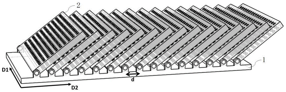
图2为根据本发明实施例的一种吸声装置的吸声主体的结构示意图;2 is a schematic structural diagram of a sound absorbing body of a sound absorbing device according to an embodiment of the present invention;
图3为根据本发明实施例的一种吸声装置的谐振单元的结构示意图;3 is a schematic structural diagram of a resonance unit of a sound absorbing device according to an embodiment of the present invention;
图4为根据本发明实施例的一种吸声装置的结构模块示意图;4 is a schematic diagram of a structural module of a sound absorption device according to an embodiment of the present invention;
图5为根据本发明实施例1的吸声性能曲线图;Fig. 5 is the sound absorption performance curve diagram according to Embodiment 1 of the present invention;
图6为根据本发明实施例2的吸声性能曲线图;6 is a sound absorption performance curve diagram according to Embodiment 2 of the present invention;
图7为根据本发明实施例3的吸声性能曲线图;7 is a sound absorption performance curve diagram according to Embodiment 3 of the present invention;
图8为根据本发明实施例2和实施例3中的谐振单元转角为20°时的吸声性能曲线图;FIG. 8 is a sound absorption performance curve diagram when the resonant unit rotation angle is 20° according to Embodiment 2 and Embodiment 3 of the present invention;
图9为根据本发明实施例4的吸声性能曲线图;9 is a sound absorption performance curve diagram according to
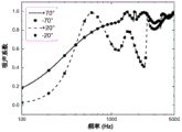
图10为根据本发明实施例5中的声场入射角为±20°和±70°时的吸声性能曲线图;10 is a graph of sound absorption performance when the sound field incident angle is ±20° and ±70° according to
图11为根据本发明实施例5中的谐振单元转角为0°、20°、40°、60°和80°时的吸声性能曲线图;11 is a graph showing the sound absorption performance when the resonant unit rotation angles are 0°, 20°, 40°, 60° and 80° according to
图12为根据本发明实施例3和对比例1-3中的谐振单元转角为20°时的吸声性能曲线图。FIG. 12 is a graph showing the sound absorption performance when the resonant unit in Example 3 and Comparative Examples 1-3 according to the present invention has a rotation angle of 20°.
具体实施方式Detailed ways
下面结合附图和实施例,对本发明的具体实施方式作进一步详细描述。以下实施例用于说明本发明,但不用来限制本发明的范围。The specific embodiments of the present invention will be described in further detail below with reference to the accompanying drawings and embodiments. The following examples are intended to illustrate the present invention, but not to limit the scope of the present invention.
参见图2所示,一种吸声结构,其包括吸声主体,吸声主体包括背板1和谐振单元2。谐振单元2的一端铰接于背板1上,且谐振单元2能够相对于背板1发生旋转。背板1上安装的谐振单元2至少有两个,且谐振单元2之间均平行设置。Referring to FIG. 2 , a sound absorbing structure includes a sound absorbing body, and the sound absorbing body includes a back plate 1 and a resonance unit 2 . One end of the resonance unit 2 is hinged on the backplane 1 , and the resonance unit 2 can rotate relative to the backplane 1 . There are at least two resonance units 2 installed on the backplane 1, and the resonance units 2 are all arranged in parallel.
谐振单元2为扁平的立方体结构,且具有中空的内腔。谐振单元的长、宽围成的两个较大表面采用具有开孔的微穿孔吸声板,而其另外四个侧面均采用无穿孔板。声波以一定角度由谐振单元2的微穿孔吸声板进入谐振单元2时,在谐振单元2中空的内腔中由于振动摩擦而损耗能量,以减弱声音的强度,达到吸声的目的。The resonance unit 2 has a flat cubic structure and has a hollow inner cavity. The two larger surfaces enclosed by the length and width of the resonant unit use micro-perforated sound-absorbing panels with openings, while the other four sides use non-perforated panels. When the sound wave enters the resonance unit 2 from the micro-perforated sound-absorbing plate of the resonance unit 2 at a certain angle, energy is lost in the hollow cavity of the resonance unit 2 due to vibration and friction, so as to reduce the intensity of the sound and achieve the purpose of sound absorption.
参见图3所示,扁平的立方体的长和宽围成两个较大的表面S1、S2;立方体的长度、厚度围成的表面S3、S4;立方体的宽度、厚度围成的表面S5、S6。表面S1、S2由微穿孔吸声板形成,谐振单元2两个较大表面S1、S2所涉及的微穿孔吸声板为穿有大量微小通孔的薄板,孔可均匀分布或随机分布;其余四个表面S3、S4、S5和S6均采用无穿孔板。Referring to Figure 3, the length and width of the flat cube form two larger surfaces S1, S2; the length and thickness of the cube form the surfaces S3, S4; the width and thickness of the cube form the surfaces S5, S6 . The surfaces S1 and S2 are formed by micro-perforated sound-absorbing plates. The micro-perforated sound-absorbing plates involved in the two larger surfaces S1 and S2 of the resonance unit 2 are thin plates with a large number of tiny through holes, and the holes can be uniformly distributed or randomly distributed; the rest The four surfaces S3, S4, S5 and S6 are made of non-perforated sheets.
立方体靠近S3的一端铰接在背板1上,多个呈扁平立方体的谐振单元2与背板1呈一定角度放置。将谐振单元2的表面S1与背板1的夹角定义为谐振单元2的转角。定义D1方向为与所述谐振单元2的长度方向平行的方向,D2方向为在背板1平面上与D1方向垂直的方向。沿D1方向设置一个或数个紧密连接的谐振单元2,且沿D2方向阵列排布。D2方向上,多个谐振单元2之间相互平行,且相邻谐振单元2之间沿D2方向的间距一定距离d。One end of the cube close to S3 is hinged on the backplane 1 , and a plurality of resonance units 2 in the form of flat cubes are placed at a certain angle with the backplane 1 . The angle between the surface S1 of the resonance unit 2 and the back plate 1 is defined as the rotation angle of the resonance unit 2 . The D1 direction is defined as a direction parallel to the longitudinal direction of the resonance unit 2 , and the D2 direction is defined as a direction perpendicular to the D1 direction on the plane of the backplane 1 . One or more closely connected resonance units 2 are arranged along the D1 direction, and are arranged in an array along the D2 direction. In the D2 direction, the plurality of resonance units 2 are parallel to each other, and the spacing between adjacent resonance units 2 along the D2 direction is a certain distance d.
谐振单元2能够相对于背板1转动以改变转角角度大小,从而改变谐振单元2相对于声源的角度,以及相邻谐振单元2之间腔体的大小,进而改变吸声装置对噪声的吸收频段,达到更好的吸声效果。针对不同频段的声源,只需改变谐振单元2的转角大小,以针对性地增强装置整体的吸声效果,拓宽了吸声频段,调控方式简便、结构设置简单。The resonance unit 2 can be rotated relative to the back plate 1 to change the angle of the turning angle, thereby changing the angle of the resonance unit 2 relative to the sound source and the size of the cavity between adjacent resonance units 2, thereby changing the absorption of noise by the sound absorbing device frequency range to achieve better sound absorption. For sound sources in different frequency bands, it is only necessary to change the size of the corner of the resonance unit 2 to specifically enhance the overall sound absorption effect of the device, broaden the sound absorption frequency band, and the control method is simple and the structure setting is simple.
在一个具体的实施例中,转角的角度范围为a°~(180-a)°,其中a为相邻谐振单元2相互搭接时与背板1的夹角。In a specific embodiment, the angle of the rotation angle ranges from a° to (180-a)°, where a is the included angle between the adjacent resonance units 2 and the backplane 1 when they overlap each other.
在另一个具体的实施例中,背板1采用具有隔音效果的平板,该平板优选为隔音板。以更进一步增强隔音吸声的效果。In another specific embodiment, the back plate 1 adopts a flat plate with sound insulation effect, and the flat plate is preferably a sound insulation board. To further enhance the effect of sound insulation and sound absorption.
在另一个具体的实施例中,背板1原则上使用具有较好隔声效果的平板,如果安装于墙壁,墙体即可作为背板。In another specific embodiment, in principle, the back plate 1 uses a flat plate with better sound insulation effect. If it is installed on the wall, the wall can be used as the back plate.
谐振单元2可以为大型结构,也可以为微型结构。谐振单元2的长度尺寸和数量依应用的领域、具体工况,如墙面面积,任意选择。当吸声主体应用于大型场所时,谐振单元2可以相应有较大的体积,即谐振单元2的立方体结构的两最大表面的面积大,立方体的厚度也相对较大;当吸声主体应用于比较小的场景时,谐振单元2的体积较小,即谐振单元2的立方体的两最大表面的面积小,立方体的厚度也较小。可以理解的是,谐振单元2根据应用场所的不同,能够相应的设置立方体的外形尺寸。The resonance unit 2 may be a large-scale structure or a micro-structure. The length, size and quantity of the resonance unit 2 can be arbitrarily selected according to the application field and specific working conditions, such as the wall area. When the sound-absorbing body is applied to large places, the resonance unit 2 can have a correspondingly larger volume, that is, the area of the two largest surfaces of the cubic structure of the resonance unit 2 is large, and the thickness of the cube is relatively large; when the sound-absorbing body is applied to In a relatively small scene, the volume of the resonance unit 2 is small, that is, the area of the two largest surfaces of the cube of the resonance unit 2 is small, and the thickness of the cube is also small. It can be understood that, according to different application places, the resonance unit 2 can correspondingly set the external dimensions of the cube.
在一个具体的实施例中,在谐振单元2的中空内腔内填充多孔吸声材料。具体地,多孔吸声材料可为有机纤维材料、麻棉毛毡、无机纤维材料、玻璃棉、岩棉、矿棉,脲醛泡沫塑料,氨基甲酸脂泡沫塑料等。在中空内腔内填充吸声材料,能够增加声波在谐振单元2内部振动摩擦而耗损的能量,尤其在微穿孔板孔径较大时,可达到增强吸声效果的目的。In a specific embodiment, the hollow cavity of the resonance unit 2 is filled with a porous sound absorbing material. Specifically, the porous sound-absorbing material may be organic fiber material, hemp cotton felt, inorganic fiber material, glass wool, rock wool, mineral wool, urea-formaldehyde foam, urethane foam, and the like. Filling the hollow cavity with sound-absorbing material can increase the energy lost by the sound wave due to vibration and friction inside the resonance unit 2, especially when the aperture of the micro-perforated plate is large, the purpose of enhancing the sound-absorbing effect can be achieved.
在另一个具体的实施例中,相邻谐振单元2之间沿D2方向的间距小于谐振单元2的宽度,以保证在谐振单元2在其转角达到最小值a°的情况下相互层叠、相互搭接,即在此情况下存在背板1法线方向穿过至少两个谐振单元2的情况。In another specific embodiment, the distance between adjacent resonance units 2 along the D2 direction is smaller than the width of the resonance unit 2 to ensure that the resonance units 2 are stacked and overlapped with each other when the rotation angle of the resonance units 2 reaches the minimum value a° In this case, the normal direction of the backplane 1 passes through at least two resonance units 2 .
当谐振单元2相对于背板1的角度一定时,相邻谐振单元2之间形成的空腔的大小也会影响到吸声的频段和/或效果。因此,合理的设置相邻谐振单元2之间的间距,能够有效的提高吸声的效果。When the angle of the resonance unit 2 relative to the backplane 1 is constant, the size of the cavity formed between the adjacent resonance units 2 will also affect the frequency band and/or effect of sound absorption. Therefore, reasonable setting of the spacing between adjacent resonance units 2 can effectively improve the effect of sound absorption.
由于相邻的谐振单元2之间沿D2方向的间距小于谐振单元2的宽度,当谐振单元2相对于背板1转动一定角度时,除了吸声主体端部处的第一个谐振单元2或最后一个谐振单元2,吸声主体中的谐振单元2上还可以形成层叠的结构,以与谐振单元2协同作用,增强声波能量的耗损,有效的增强吸声的效果。Since the distance between adjacent resonating units 2 along the D2 direction is smaller than the width of the resonating units 2, when the resonating units 2 are rotated relative to the back plate 1 at a certain angle, except for the first resonating unit 2 at the end of the sound absorbing body or the The last resonance unit 2, the resonance unit 2 in the sound absorbing body can also form a laminated structure to cooperate with the resonance unit 2 to enhance the loss of sound wave energy and effectively enhance the effect of sound absorption.
更进一步地,谐振单元2能够相对于背板1转动的同时,还能够相对于背板1沿D2方向滑动位置。谐振单元2在背板1上滑动,以调整谐振单元2两两之间的间距。通过调整相邻的谐振单元2之间的间距,以改变谐振单元2之间层叠而形成的空腔的大小,或者调整谐振的单元2之间层叠的数量,从而调整谐振单元2吸声的频段和效果。Furthermore, the resonance unit 2 can be rotated relative to the backplane 1 and can also be slid relative to the backplane 1 along the D2 direction. The resonance units 2 slide on the backplane 1 to adjust the spacing between the resonance units 2 . By adjusting the spacing between adjacent resonant units 2, the size of the cavity formed by the stacking of the resonance units 2 is changed, or the number of stacks between the resonant units 2 is adjusted, so as to adjust the sound absorption frequency band of the resonance unit 2. and effects.
根据声源的特点或吸声的要求,适当的调整相邻谐振单元2之间的间距,以使谐振单元2之间形成的空腔的不同,或者,谐振单元2之间形成层叠的数量不同,以改变吸声主体的吸声效果。According to the characteristics of the sound source or the requirements of sound absorption, the distance between the adjacent resonance units 2 is appropriately adjusted so that the cavities formed between the resonance units 2 are different, or the number of stacks formed between the resonance units 2 is different. , to change the sound absorption effect of the sound absorption body.
在另一个具体的实施例中,还包括用于控制所述谐振单元的状态参数发生变化的控制模块,所述状态参数包括谐振单元2与背板1的角度,和/或谐振单元2之间的距离。参见图2所示,控制模块包括可通过电子控制移动的传动装置,传动装置布置于背板1和谐振单元2之间,以使谐振单元2的转角和/或谐振单元2之间的间距进行一定范围内精准的调节。In another specific embodiment, it further includes a control module for controlling a state parameter of the resonance unit to change, the state parameter including the angle between the resonance unit 2 and the backplane 1 , and/or between the resonance unit 2 the distance. Referring to FIG. 2 , the control module includes a transmission device that can be moved by electronic control, and the transmission device is arranged between the backplane 1 and the resonance unit 2, so that the rotation angle of the resonance unit 2 and/or the spacing between the resonance units 2 can be adjusted. Accurate adjustment within a certain range.
谐振单元2既能够相对于背板1发生转动,也能够相对于背板1发生水平方向的滑动。驱动谐振单元2运动的传动装置可采用本领域常用的机构或电动装置。其中,可采用手动旋钮,或推杆电机带动内部连接杆,或电动铰链实现谐振单元2的转动。另一方面,可以使用电动滑轨控制谐振单元的滑动。此外,电动滑轨还可以具有齿轮定位系统,以精确控制相邻谐振单元2之间的距离。增加谐振单元2的间距后,背板1外围多余的谐振单元2可布置于吸声主体的任意位置,如垂直紧密排列于结构平面外围。The resonance unit 2 can rotate relative to the back plate 1 and can also slide in the horizontal direction relative to the back plate 1 . The transmission device for driving the resonant unit 2 to move can use a mechanism or an electric device commonly used in the art. Among them, a manual knob, or a push rod motor to drive an internal connecting rod, or an electric hinge can be used to realize the rotation of the resonance unit 2 . On the other hand, the sliding of the resonance unit can be controlled using an electric slide. In addition, the electric sliding rail can also have a gear positioning system to precisely control the distance between adjacent resonance units 2 . After increasing the spacing of the resonance units 2, the redundant resonance units 2 on the periphery of the backplane 1 can be arranged at any position of the sound absorbing body, such as vertically and closely arranged on the periphery of the structure plane.
在对谐振单元2进行调节的过程中,还可以采用自动控制的方式,以根据声场的特点,自动对谐振单元2进行调控。参见图4所示,用于自动控制谐振单元2的控制模块还包括声传感器和计算模块。声传感器与吸声主体设置于声场中的适当位置,其直接接收声场的声音信号,将该声音信号转换为电信号,并将该电信号输出至计算模块,计算模块根据该电信号控制谐振单元2的转动或滑动。In the process of adjusting the resonance unit 2, an automatic control method may also be adopted, so as to automatically adjust the resonance unit 2 according to the characteristics of the sound field. Referring to FIG. 4 , the control module for automatically controlling the resonance unit 2 further includes an acoustic sensor and a calculation module. The sound sensor and the sound-absorbing body are arranged at appropriate positions in the sound field, which directly receive the sound signal of the sound field, convert the sound signal into an electrical signal, and output the electrical signal to the calculation module, which controls the resonance unit according to the electrical signal. 2 turns or slides.
在计算模块中预存谐振单元2的状态参数与吸收系数、吸声频段的关系数据,当声传感器感应到环境声信号,计算模块根据该信号进行频谱分析,获得频谱特征信息,并根据期望的吸声效果,将获得的频谱特征信息与预存的关系数据进行对比,得到适当的谐振单元2的状态参数信息,以控制谐振单元2转动至相应的角度和/或滑动位置,以使谐振单元2处于合适的位置,实现主动控制吸声的目的,达到更好的吸声效果。上述期望的吸声效果由用户认为指定,可以是在某一频段内的达到特定吸声系数,也可以是在某种状态下具备或不具备吸声效果。The relationship data between the state parameters of the resonance unit 2, the absorption coefficient, and the sound absorption frequency band are pre-stored in the calculation module. When the acoustic sensor senses the ambient sound signal, the calculation module performs spectrum analysis according to the signal to obtain spectrum characteristic information, and according to the expected absorption Acoustic effect, the obtained spectral characteristic information is compared with the pre-stored relational data, and the appropriate state parameter information of the resonance unit 2 is obtained to control the resonance unit 2 to rotate to the corresponding angle and/or sliding position, so that the resonance unit 2 is in the Appropriate position to achieve the purpose of actively controlling sound absorption and achieve better sound absorption effect. The above-mentioned desired sound absorption effect is designated by the user, which may be a specific sound absorption coefficient within a certain frequency band, or may or may not have a sound absorption effect in a certain state.
在一个具体的实施例中,计算模块采用微处理器。In a specific embodiment, the computing module employs a microprocessor.
本发明还提供一种吸声方法,该吸声方法基于上述吸声装置得以实现,其包括:The present invention also provides a sound absorption method, which is realized based on the above sound absorption device, comprising:
1)声传感器检测环境声信号,并输入至计算模块;1) The acoustic sensor detects the ambient sound signal and inputs it to the calculation module;
2)计算模块通过计算得到适当的谐振单元2的状态参数,所述状态参数包括谐振单元2与背板1的角度,和/或谐振单元2之间的距离,根据计算结果控制传动装置,调整谐振单元2的状态参数。2) The calculation module obtains the appropriate state parameters of the resonance unit 2 through calculation, and the state parameters include the angle between the resonance unit 2 and the backplane 1, and/or the distance between the resonance units 2, and control the transmission device according to the calculation result, adjust State parameters of the resonance unit 2.
声传感器获取环境声场的声音信号后,将该声音信号转换为电信号后,输送至计算模块。计算模块根据所获取的电信号,计算得到谐振单元2的状态参数。控制模块根据计算得到的状态参数,控制传动装置以调控谐振单元2相对于背板1的转角的大小,以及谐振单元2之间的间距的大小,使吸声主体相对于目前的环境声场以及吸声需求,其吸声效果/状态为最佳。After the sound sensor acquires the sound signal of the ambient sound field, the sound signal is converted into an electrical signal and then sent to the calculation module. The calculation module calculates and obtains the state parameters of the resonance unit 2 according to the obtained electrical signal. According to the calculated state parameters, the control module controls the transmission device to adjust the size of the rotation angle of the resonance unit 2 relative to the backplane 1, and the size of the distance between the resonance units 2, so that the sound-absorbing body is relative to the current ambient sound field and the sound absorption. The sound absorption effect/state is the best.
在一个具体的实施例中,所述计算模块基于所述声音信号进行频谱分析以获取频谱特征信息,将所述频谱特征信息与所述计算模块中预存的关系数据进行对比,以获取所述谐振单元2的状态参数;所述关系数据为谐振单元2的历史状态参数与吸收系数、吸声频段的最优对应关系。In a specific embodiment, the calculation module performs spectrum analysis based on the sound signal to obtain spectrum feature information, and compares the spectrum feature information with relational data pre-stored in the calculation module to obtain the resonance The state parameters of the unit 2; the relationship data is the optimal corresponding relationship between the historical state parameters of the resonance unit 2, the absorption coefficient, and the sound absorption frequency band.
在计算模块中预存不同吸收系数、吸声频段对应的优化的谐振单元2的历史状态参数。当声传感器感应到环境声场的声音信号,其将该声音信号转换为电信号并输送至计算模块。The optimized historical state parameters of the resonance unit 2 corresponding to different absorption coefficients and sound absorption frequency bands are pre-stored in the calculation module. When the sound sensor senses the sound signal of the ambient sound field, it converts the sound signal into an electrical signal and sends it to the computing module.
计算模块根据该电信号进行频谱分析,获得频谱特征信息,并根据期望的吸声效果,将获得的频谱特征信息与预存的关系数据进行对比,得到适当的谐振单元2的状态参数信息。The calculation module performs spectrum analysis according to the electrical signal to obtain spectral characteristic information, and compares the obtained spectral characteristic information with the pre-stored relational data according to the desired sound absorption effect to obtain appropriate state parameter information of the resonance unit 2 .
控制模块根据该状态参数信息调控传动装置,以控制谐振单元2转动至相应的角度和/或滑动位置,以使谐振单元2处于合适的位置,实现主动控制吸声的目的,达到更好的吸声效果。上述期望的吸声效果由用户人为指定,可以是在某一频段内达到特定吸声系数,也可以是在某种状态下具备或不具备吸声效果。The control module regulates the transmission device according to the state parameter information to control the resonant unit 2 to rotate to the corresponding angle and/or sliding position, so that the resonant unit 2 is in a suitable position, so as to achieve the purpose of actively controlling sound absorption and achieve better sound absorption. sound effect. The above-mentioned desired sound absorption effect is manually specified by the user, which may be to achieve a specific sound absorption coefficient in a certain frequency band, or to have or not to have the sound absorption effect in a certain state.
为具体说明不同转角、相邻谐振单元间的间距,及谐振单元规格对吸声效果的影响,根据具体数据进行说明。In order to specifically explain the influence of different rotation angles, the spacing between adjacent resonant units, and the resonator unit specifications on the sound absorption effect, the description is based on specific data.
实施例1Example 1
形成谐振单元2的立方体的宽度为0.15m,且沿该宽度一侧的侧面安装于背板1上,理论证明,在标准的测试环境下,立方体的长度与吸声效果无关。因此立方体的长度可根据工作环境任意选取。立方体厚度为0.03m。微穿孔吸声板板厚0.005m,表面上分布有孔径为2×10⁻⁴m的圆孔,孔隙率为0.05。谐振单元之间的间距为0.1m。The width of the cube forming the resonance unit 2 is 0.15m, and it is mounted on the backplane 1 along one side of the width. It is theoretically proved that in a standard test environment, the length of the cube has nothing to do with the sound absorption effect. Therefore, the length of the cube can be arbitrarily selected according to the working environment. The cube thickness is 0.03m. The thickness of the micro-perforated sound-absorbing board is 0.005 m, and the surface is distributed with circular holes with a diameter of 2 × 10 -4 m, and the porosity is 0.05. The spacing between the resonance units is 0.1m.
参见图5所示,当声场以垂直于背板1的方向入射时,由谐振单元2的转角分别为90°、55°和20°时的吸声系数可知,随着谐振单元转角减小,0Hz—1000Hz的第一吸收峰的吸声系数逐渐增大,而1000Hz—2000Hz的第二吸收峰则随着该转角的减小而降低,说明通过改变谐振单元2的转角,能够在较宽频带内对结构的吸声能力进行调节。Referring to Figure 5, when the sound field is incident in a direction perpendicular to the backplane 1, the sound absorption coefficients when the rotation angles of the resonant unit 2 are 90°, 55° and 20° respectively show that as the resonator unit rotation angle decreases, The sound absorption coefficient of the first absorption peak of 0Hz-1000Hz gradually increases, while the second absorption peak of 1000Hz-2000Hz decreases with the decrease of the rotation angle. The sound absorption capacity of the structure can be adjusted internally.
实施例2Example 2
相比实施例1增大了微穿孔吸声板的孔径,并且在谐振单元2的腔体内部填充多孔材料。与实施例1的不同之处在于增大了微穿孔吸声板的孔径,并且在谐振单元2的腔体内部填充多孔材料。微穿孔吸声板表面上分布的圆孔的孔径为0.001m,且立方体的中空内腔内设置有多孔吸声材料,多孔吸声材料的流阻率为4896Pa·s/m2。Compared with Example 1, the aperture of the micro-perforated sound-absorbing plate is increased, and the cavity of the resonance unit 2 is filled with porous materials. The difference from Embodiment 1 is that the aperture of the micro-perforated sound-absorbing plate is increased, and the cavity of the resonance unit 2 is filled with porous materials. The diameter of the circular holes distributed on the surface of the micro-perforated sound-absorbing plate is 0.001 m, and a porous sound-absorbing material is arranged in the hollow cavity of the cube, and the flow resistivity of the porous sound-absorbing material is 4896 Pa·s/m 2 .
当声场以垂直于背板1的方向入射时,谐振单元2转角分别为90°、55°和20°时的吸声系数如图6所示。与实施例1相比,谐振单元2转角仍然具有明显的调节作用。增大微穿孔板孔径同时在谐振单元2腔体内部添加多孔材料后,第一吸收峰的峰值和频域有一定的提高和拓宽。When the sound field is incident in a direction perpendicular to the backplane 1, the sound absorption coefficients when the resonant unit 2 is rotated at 90°, 55° and 20° are shown in Fig. 6 . Compared with Embodiment 1, the rotation angle of the resonance unit 2 still has an obvious adjustment effect. After the aperture of the micro-perforated plate is increased and the porous material is added inside the cavity of the resonance unit 2, the peak value and frequency domain of the first absorption peak are improved and broadened to a certain extent.
实施例3Example 3
在实施例2的基础上,调整谐振单元2的几何尺寸和排布。与实施例2的不同之处在于:立方体的宽度为0.1m,立方体厚度为0.01m,谐振单元2间距为0.05m。On the basis of Embodiment 2, the geometric size and arrangement of the resonance unit 2 are adjusted. The difference from Embodiment 2 is that the width of the cube is 0.1 m, the thickness of the cube is 0.01 m, and the spacing between the resonance units 2 is 0.05 m.
参见图7所示,当声场以垂直于背板1的方向入射时,由谐振单元2的转角分别为90°、55°和20°时的吸声系数可知,谐振单元2相对于背板1转动的角度对于吸声频段的影响依然非常明显。同时,参见图8所示,相比于实施例2,将立方体宽度和厚度都相对减小,而其他条件不变时,吸声频段向高频方向移动。Referring to FIG. 7 , when the sound field is incident in a direction perpendicular to the backplane 1, the sound absorption coefficients of the resonant unit 2 when the rotation angles are 90°, 55° and 20° respectively show that the resonant unit 2 is relatively opposite to the backplane 1. The effect of the rotation angle on the sound absorption frequency band is still very obvious. At the same time, as shown in FIG. 8 , compared with Example 2, the width and thickness of the cube are relatively reduced, and when other conditions remain unchanged, the sound absorption frequency band moves to the high frequency direction.
实施例4Example 4
将谐振单元2的规格缩小,具体地,立方体的宽度为0.01m,且沿该宽度一侧的侧面安装于背板1上,立方体的长度为立方体的长度可根据工作环境任意选取。立方体厚度为0.002m。微穿孔吸声板板厚0.001m,表面上分布有孔径为0.0001m的圆孔,孔隙率为0.05。谐振单元之间的间距为0.005m,谐振单元内部腔体内填充的多孔材料的流阻率为4896Pa·s/m2。The size of the resonant unit 2 is reduced. Specifically, the width of the cube is 0.01 m, and it is installed on the backplane 1 along one side of the width. The length of the cube can be arbitrarily selected according to the working environment. The cube thickness is 0.002m. The thickness of the micro-perforated sound-absorbing plate is 0.001m, and the surface is distributed with circular holes with a diameter of 0.0001m, and the porosity is 0.05. The spacing between the resonance units is 0.005m, and the flow resistivity of the porous material filled in the cavity of the resonance unit is 4896 Pa·s/m 2 .
参见图9所示,当声场以垂直于背板1的方向入射时,由谐振单元2的转角分别为90°、55°和20°时的吸声系数可知,当谐振单元2的规格尺寸缩小后,不仅在高频具有良好的吸声效果,并且吸声系数大小仍然可以通过调整转角大小进行调整。该结果反应了本发明的吸声结构不仅可以在宏观尺度的建筑声学和环境声学等方面应用,在小尺度的吸声问题中也具有应用价值。Referring to FIG. 9 , when the sound field is incident in a direction perpendicular to the backplane 1, the sound absorption coefficients when the rotation angles of the resonant unit 2 are 90°, 55° and 20° respectively show that when the size of the resonator unit 2 is reduced Afterwards, it not only has a good sound absorption effect at high frequencies, but the sound absorption coefficient can still be adjusted by adjusting the size of the corner. This result reflects that the sound-absorbing structure of the present invention can not only be applied in macro-scale architectural acoustics and environmental acoustics, but also has application value in small-scale sound absorption problems.
实施例5Example 5
采用与实施例3相同的吸声结构(谐振单元2转角为20°),改变声场入射角度。在此实施例中,考虑声场的波矢量方向限制在D2方向直线与背板1法线方向构成的平面内。与实施例3的不同之处在于:仅改变生产入射角度。参见图10所示,声场入射角度(入射声场方向与背板法线夹角)为-20°和20°的吸声曲线相同;声场入射角度为-70°和70°的吸声曲线也相同,即声场相对于背板1的入射角度大小有关,而与入射的方向无关。The same sound absorption structure as in Example 3 (the rotation angle of the resonance unit 2 is 20°) is used, and the incident angle of the sound field is changed. In this embodiment, the direction of the wave vector considering the sound field is limited to the plane formed by the D2 direction straight line and the normal direction of the back plate 1 . The difference from Example 3 is that only the production incident angle is changed. Referring to Figure 10, the sound absorption curves of the sound field incident angle (the angle between the incident sound field direction and the normal of the back plate) are the same as -20° and 20°; the sound absorption curves of the sound field incident angles of -70° and 70° are also the same , that is, the size of the incident angle of the sound field relative to the backplane 1 is related to the incident direction, regardless of the incident direction.
参见图11所示,声场入射角以0°、20°、40°、60°和80°时的吸声系数可知,对于各入射角的声场均有良好的吸声性能,且声场入射角较大时,吸声性能更优。Referring to Figure 11, the sound absorption coefficients at the incident angles of the sound field are 0°, 20°, 40°, 60° and 80°. When it is larger, the sound absorption performance is better.
为进一步说明谐振单元2的吸声效果,将吸声主体与目前的常规设置方式进行比较。In order to further illustrate the sound absorption effect of the resonance unit 2, the sound absorption body is compared with the current conventional arrangement.
对比例1Comparative Example 1
第一种对照结构为多孔吸声材料阵列。该结构相当于在实施例3对应的几何结构中不使用谐振单元,而使用与谐振单元2相同体积的立方体多孔材料代替。立方体多孔材料的流阻率同样为4896Pa·s/m2,排布方式与实施例3中的谐振单元2相同。The first control structure was an array of porous sound absorbing materials. This structure is equivalent to not using a resonant unit in the geometric structure corresponding to Embodiment 3, but using a cubic porous material of the same volume as that of the resonant unit 2 instead. The flow resistivity of the cubic porous material is also 4896 Pa·s/m 2 , and the arrangement is the same as that of the resonance unit 2 in Example 3.
如图12所示,该结构的吸声频率集中在高频,与普通的多孔吸声材料类似。As shown in Figure 12, the sound absorption frequency of this structure is concentrated at high frequencies, which is similar to that of ordinary porous sound absorption materials.
对比例2Comparative Example 2
第二种典型结构为微穿孔板吸声结构。为便于对比,采用实施例3中谐振单元2所采用的微穿孔板。将单层微穿孔板平行于背板1,并高于背板1一定距离处设置。该距离等于实施例3中结构在谐振单元2转角为20°时所占据背板1上方的高度。在微穿孔板与背板1之间的空间填充实施例3中采用的流阻率为4896Pa·s/m2的多孔吸声材料。The second typical structure is the micro-perforated plate sound-absorbing structure. For the convenience of comparison, the micro-perforated plate used in the resonance unit 2 in Example 3 is used. The single-layer micro-perforated plate is set parallel to the backplane 1 and at a certain distance higher than the backplane 1 . This distance is equal to the height above the backplane 1 occupied by the structure in Embodiment 3 when the resonant unit 2 has a rotation angle of 20°. The space between the micro-perforated plate and the back plate 1 is filled with a porous sound-absorbing material with a flow resistivity of 4896 Pa·s/m 2 used in Example 3.
如图12所示,该结构吸声频带宽,但是吸声略差,并且在穿孔板加工完成后吸声系数就被锁定,无法进行调节。As shown in Figure 12, the structure has a wide sound absorption frequency band, but the sound absorption is slightly poor, and the sound absorption coefficient is locked after the perforated plate is processed and cannot be adjusted.
对比例3Comparative Example 3
第三种典型结构为多层微穿孔板吸声结构。为便于对比,采用实施例3中谐振单元2所采用的微穿孔板。将四层微孔板以相同的间距布置于背板1上方,使结构整体高度与对比例2中的结构相同。在微穿孔板与背板1之间的空间以及微穿孔板之间的空间填充实施例3中采用的流阻率为4896Pa·s/m2的多孔吸声材料。The third typical structure is the multi-layer micro-perforated plate sound-absorbing structure. For the convenience of comparison, the micro-perforated plate used in the resonance unit 2 in Example 3 is used. Four-layer microplates were arranged above the backplane 1 at the same spacing, so that the overall height of the structure was the same as that of the structure in Comparative Example 2. The space between the micro-perforated plate and the back plate 1 and the space between the micro-perforated plates were filled with the porous sound absorbing material with the flow resistivity of 4896 Pa·s/m 2 used in Example 3.
如图12所示,该结构在第一吸收峰的吸声效果与实施例3接近,但不存在第二吸收峰,同时该结构无法进行吸声系数和吸声频带的调节。As shown in FIG. 12 , the sound absorption effect of the structure at the first absorption peak is close to that of Example 3, but there is no second absorption peak, and the structure cannot adjust the sound absorption coefficient and sound absorption frequency band.
实施例3所述结构(谐振单元转角为20°)与对比例1-3本领域典型吸声结构在环境声场的入射角为0°时的吸声系数对比如图12所示。结果表明了本发明在与其他类似吸声结构的对比中,吸声效果在高、低频均具有一定优势,并且该吸声结构还可以通过控制谐振单元2转角和间距调整吸声系数,更具灵活性。Figure 12 shows the comparison of the sound absorption coefficient of the structure described in Example 3 (the resonant unit rotation angle is 20°) and the typical sound absorption structure in the field of Comparative Examples 1-3 when the incident angle of the ambient sound field is 0°. The results show that compared with other similar sound-absorbing structures, the sound-absorbing effect of the present invention has certain advantages at high and low frequencies, and the sound-absorbing structure can also adjust the sound-absorbing coefficient by controlling the rotation angle and spacing of the resonant unit 2, more flexibility.
本发明的一种基于夜蛾翅膀的仿生吸声结构,包括背板1和安装于背板1上的多个谐振单元2,谐振单元2能够相对于背板1转动,也能够在背板1上滑动,以调节谐振单元2之间的间距。谐振单元2采用可转动和可滑动的方式,使吸声主体对于声场的吸声频段更宽、吸声效果更好。A bionic sound-absorbing structure based on the wings of the noctuid moth of the present invention includes a backboard 1 and a plurality of resonance units 2 mounted on the backboard 1. The resonance units 2 can rotate relative to the backboard 1, and can also rotate on the backboard 1. Slide up to adjust the spacing between the resonance units 2. The resonance unit 2 adopts a rotatable and slidable manner, so that the sound-absorbing body has a wider sound-absorbing frequency band for the sound field and a better sound-absorbing effect.
更进一步,为便于对吸声主体的自动控制,还设置有包括传动装置、声传感器和计算模块的控制模块,根据声场的位置和声音频段,自动调节谐振单元2的转角和/或谐振单元2之间的间距。Further, in order to facilitate the automatic control of the sound-absorbing main body, a control module including a transmission device, an acoustic sensor and a calculation module is also provided, and according to the position of the sound field and the sound frequency band, the rotation angle of the resonance unit 2 and/or the resonance unit 2 are automatically adjusted. spacing between.
本发明的一种吸声方法,基于上述吸声装置得以实现,其由声传感器获取环境声场的声音信号,并将该声音信号转换为电信号以输送至控制模块的计算模块,由计算模块基于该电信号计算得到谐振单元2的状态参数,并基于该状态参数调控传动装置,以调控谐振单元2的状态,即调控谐振单元2相对于背板1的转角的大小,以及谐振单元2之间的间距的大小,以达到更好地预期效果。A sound absorption method of the present invention is realized based on the above sound absorption device. The sound sensor acquires the sound signal of the ambient sound field, and converts the sound signal into an electrical signal to be sent to the calculation module of the control module. The electrical signal is calculated to obtain the state parameters of the resonant unit 2, and based on the state parameters, the transmission device is adjusted to adjust the state of the resonant unit 2, that is, to adjust the size of the rotation angle of the resonant unit 2 relative to the backplane 1, and between the resonant units 2. The size of the spacing to achieve better expected results.
最后,本发明的方法仅为较佳的实施方案,并非用于限定本发明的保护范围。凡在本发明的精神和原则之内,所作的任何修改、等同替换、改进等,均应包含在本发明的保护范围之内。Finally, the method of the present invention is only a preferred embodiment, and is not intended to limit the protection scope of the present invention. Any modification, equivalent replacement, improvement, etc. made within the spirit and principle of the present invention shall be included within the protection scope of the present invention.
Claims (10)
Priority Applications (1)
| Application Number | Priority Date | Filing Date | Title |
|---|---|---|---|
| CN201710448424.8A CN107316632B (en) | 2017-06-14 | 2017-06-14 | A sound absorption device and sound absorption method |
Applications Claiming Priority (1)
| Application Number | Priority Date | Filing Date | Title |
|---|---|---|---|
| CN201710448424.8A CN107316632B (en) | 2017-06-14 | 2017-06-14 | A sound absorption device and sound absorption method |
Publications (2)
| Publication Number | Publication Date |
|---|---|
| CN107316632A CN107316632A (en) | 2017-11-03 |
| CN107316632B true CN107316632B (en) | 2020-08-18 |
Family
ID=60183570
Family Applications (1)
| Application Number | Title | Priority Date | Filing Date |
|---|---|---|---|
| CN201710448424.8A Active CN107316632B (en) | 2017-06-14 | 2017-06-14 | A sound absorption device and sound absorption method |
Country Status (1)
| Country | Link |
|---|---|
| CN (1) | CN107316632B (en) |
Families Citing this family (12)
| Publication number | Priority date | Publication date | Assignee | Title |
|---|---|---|---|---|
| CN108120001A (en) * | 2017-12-07 | 2018-06-05 | 珠海格力电器股份有限公司 | Shell assembly and dehumidifier with same |
| CN108845291B (en) * | 2018-06-12 | 2025-05-06 | 江苏大学 | An underwater sound source positioning system and method based on phononic crystal sensing |
| CN108731072A (en) * | 2018-07-14 | 2018-11-02 | 佛山市云米电器科技有限公司 | A kind of kitchen ventilator with the cellular noise filtering device of multilayer |
| CN108916939A (en) * | 2018-07-14 | 2018-11-30 | 佛山市云米电器科技有限公司 | A kind of kitchen ventilator with the cellular noise filtering device by arrangement area distribution |
| CN108954431A (en) * | 2018-07-14 | 2018-12-07 | 佛山市云米电器科技有限公司 | A kind of band can reduce the kitchen ventilator of the cellular noise filtering device of specific unifrequency |
| CN108954432A (en) * | 2018-07-14 | 2018-12-07 | 佛山市云米电器科技有限公司 | A kind of kitchen ventilator having multi-frequency noise filtering device |
| CN108954436A (en) * | 2018-07-14 | 2018-12-07 | 佛山市云米电器科技有限公司 | A kind of kitchen ventilator with the cellular noise filtering device of multi-frequency |
| US11905703B2 (en) * | 2018-12-21 | 2024-02-20 | The Hong Kong University Of Science And Technology | Soft acoustic boundary plate |
| CN111489732B (en) * | 2020-03-16 | 2024-01-19 | 中国农业大学 | Acoustic super-surface and design method thereof and acoustic device |
| CN112634852B (en) * | 2020-12-22 | 2024-07-23 | 中国科学院声学研究所 | Multistage high-order resonance composite muffler for controlling pipeline noise |
| KR102612637B1 (en) * | 2021-03-19 | 2023-12-13 | 국방과학연구소 | Active Multi-scale Sound Absorber and Fabrication Method Thereof |
| CN113488013B (en) * | 2021-07-30 | 2024-10-29 | 中国人民解放军海军工程大学 | Broadband folding back cavity micro-perforation sound absorption structure |
Citations (1)
| Publication number | Priority date | Publication date | Assignee | Title |
|---|---|---|---|---|
| DE202008007381U1 (en) * | 2008-02-26 | 2008-10-16 | Musikhaus Thomann E. K. | Return sound shield |
Family Cites Families (9)
| Publication number | Priority date | Publication date | Assignee | Title |
|---|---|---|---|---|
| JPH04137898A (en) * | 1990-09-28 | 1992-05-12 | Mazda Motor Corp | On-vehicle acoustic equipment |
| ITMI20020409A1 (en) * | 2002-02-28 | 2003-08-28 | Isopol Srl | HIGH SOUND ABSORBING PROPERTIES |
| CN102332259B (en) * | 2011-10-12 | 2012-07-25 | 中国科学院合肥物质科学研究院 | Adaptive micro-perforated plate sound absorber and real-time micropore adjusting method thereof |
| US9520121B2 (en) * | 2013-06-25 | 2016-12-13 | The Hong Kong University Of Science And Technology | Acoustic and vibrational energy absorption metamaterials |
| CN104575484A (en) * | 2014-12-30 | 2015-04-29 | 北京市劳动保护科学研究所 | Controllable compound sound absorption structure |
| CN204360777U (en) * | 2014-12-30 | 2015-05-27 | 北京市劳动保护科学研究所 | A kind of controlled compound sound-absorption structural |
| CN104575485A (en) * | 2014-12-30 | 2015-04-29 | 北京市劳动保护科学研究所 | Controllable compound sound absorption plate |
| CN204348330U (en) * | 2014-12-30 | 2015-05-20 | 北京市劳动保护科学研究所 | A kind of controlled sound-absorbing composite board |
| CN204516347U (en) * | 2015-03-17 | 2015-07-29 | 中国科学院合肥物质科学研究院 | Based on the acoustic impedance regulating device of self-adaptation micro-perforated plate sound absorber |
-
2017
- 2017-06-14 CN CN201710448424.8A patent/CN107316632B/en active Active
Patent Citations (1)
| Publication number | Priority date | Publication date | Assignee | Title |
|---|---|---|---|---|
| DE202008007381U1 (en) * | 2008-02-26 | 2008-10-16 | Musikhaus Thomann E. K. | Return sound shield |
Non-Patent Citations (1)
| Title |
|---|
| Stable Band-Gaps in Phononic Crystals by Harnessing Hyperelastic Transformation Media;Yan Liu et al.;《arXiv》;20161231;全文 * |
Also Published As
| Publication number | Publication date |
|---|---|
| CN107316632A (en) | 2017-11-03 |
Similar Documents
| Publication | Publication Date | Title |
|---|---|---|
| CN107316632B (en) | A sound absorption device and sound absorption method | |
| CN109584855B (en) | Honeycomb-micropunch plate composite structure design method capable of adjusting sound absorption frequency | |
| US11807174B2 (en) | Partition member, vehicle, and electronic device | |
| CN111696503B (en) | Impedance enhancement perforated honeycomb panel underwater sound absorption metamaterial structure | |
| CN111739500B (en) | Underwater broadband sound-absorbing structure of perforated sandwich panels modified with damping layer | |
| CN102044239B (en) | Micro-perforated plate with resonant sound absorption structure | |
| JPS61500692A (en) | acoustic barrier | |
| CN107401225B (en) | A sound-absorbing and sound-insulating structure stacked with flexible particles | |
| CN201657284U (en) | Novel loudspeaker | |
| CN1664920A (en) | Sound attenuating structure | |
| US20210233506A1 (en) | Soundproof structure body | |
| CN205692567U (en) | A kind of low frequency composite sound absorbing device | |
| CN111739502A (en) | Damping lined hexagonal honeycomb perforated plate underwater sound-absorbing metamaterial | |
| CN110785806B (en) | sound insulation system | |
| CN107437411A (en) | A kind of low frequency composite sound absorbing device | |
| CN111739501B (en) | Damping lining level honeycomb perforated plate underwater sound absorption structure | |
| CN111816151A (en) | A double-layer honeycomb-micro-perforated structure with adjustable back cavity height and its design method | |
| JP6945006B2 (en) | Soundproof structure | |
| Song et al. | Advances and integration of noise reduction materials and structures: A review of porous materials and acoustic metamaterials | |
| CN219225891U (en) | A composite multicellular sound-absorbing structure | |
| CN201290170Y (en) | Elastic soft loudspeaker box system | |
| Nakanishi | An acoustic metasurface by applying planar periodic arrays of resonators with a multiple folded long neck for broadband sound absorption | |
| CN114783400B (en) | A parallel spring oscillator sound absorption structure | |
| CN111341292A (en) | Perforated plate laminated sound absorption structure | |
| CN112053674B (en) | Combined micro-perforated plate sound absorber structure based on piezoelectric materials and preparation method thereof |
Legal Events
| Date | Code | Title | Description |
|---|---|---|---|
| PB01 | Publication | ||
| PB01 | Publication | ||
| SE01 | Entry into force of request for substantive examination | ||
| SE01 | Entry into force of request for substantive examination | ||
| GR01 | Patent grant | ||
| GR01 | Patent grant |