CN107305452B - Display module, electronic timepiece having the same, and electronic device - Google Patents
Display module, electronic timepiece having the same, and electronic device Download PDFInfo
- Publication number
- CN107305452B CN107305452B CN201710236222.7A CN201710236222A CN107305452B CN 107305452 B CN107305452 B CN 107305452B CN 201710236222 A CN201710236222 A CN 201710236222A CN 107305452 B CN107305452 B CN 107305452B
- Authority
- CN
- China
- Prior art keywords
- light emitting
- display
- area
- pixel
- emitting pixels
- Prior art date
- Legal status (The legal status is an assumption and is not a legal conclusion. Google has not performed a legal analysis and makes no representation as to the accuracy of the status listed.)
- Active
Links
Images


Classifications
-
- G—PHYSICS
- G04—HOROLOGY
- G04G—ELECTRONIC TIME-PIECES
- G04G21/00—Input or output devices integrated in time-pieces
-
- G—PHYSICS
- G04—HOROLOGY
- G04G—ELECTRONIC TIME-PIECES
- G04G9/00—Visual time or date indication means
- G04G9/0023—Visual time or date indication means by light valves in general
- G04G9/0029—Details
- G04G9/0035—Details constructional
-
- A—HUMAN NECESSITIES
- A44—HABERDASHERY; JEWELLERY
- A44C—PERSONAL ADORNMENTS, e.g. JEWELLERY; COINS
- A44C5/00—Bracelets; Wrist-watch straps; Fastenings for bracelets or wrist-watch straps
- A44C5/14—Bracelets; Wrist-watch straps; Fastenings for bracelets or wrist-watch straps characterised by the way of fastening to a wrist-watch or the like
-
- G—PHYSICS
- G04—HOROLOGY
- G04B—MECHANICALLY-DRIVEN CLOCKS OR WATCHES; MECHANICAL PARTS OF CLOCKS OR WATCHES IN GENERAL; TIME PIECES USING THE POSITION OF THE SUN, MOON OR STARS
- G04B37/00—Cases
- G04B37/14—Suspending devices, supports or stands for time-pieces insofar as they form part of the case
- G04B37/1486—Arrangements for fixing to a bracelet
-
- G—PHYSICS
- G04—HOROLOGY
- G04G—ELECTRONIC TIME-PIECES
- G04G17/00—Structural details; Housings
- G04G17/02—Component assemblies
-
- G—PHYSICS
- G04—HOROLOGY
- G04G—ELECTRONIC TIME-PIECES
- G04G17/00—Structural details; Housings
- G04G17/02—Component assemblies
- G04G17/04—Mounting of electronic components
- G04G17/045—Mounting of the display
-
- G—PHYSICS
- G04—HOROLOGY
- G04G—ELECTRONIC TIME-PIECES
- G04G21/00—Input or output devices integrated in time-pieces
- G04G21/08—Touch switches specially adapted for time-pieces
-
- G—PHYSICS
- G04—HOROLOGY
- G04G—ELECTRONIC TIME-PIECES
- G04G9/00—Visual time or date indication means
- G04G9/02—Visual time or date indication means by selecting desired characters out of a number of characters or by selecting indicating elements the position of which represent the time, e.g. by using multiplexing techniques
- G04G9/06—Visual time or date indication means by selecting desired characters out of a number of characters or by selecting indicating elements the position of which represent the time, e.g. by using multiplexing techniques using light valves, e.g. liquid crystals
-
- G—PHYSICS
- G04—HOROLOGY
- G04G—ELECTRONIC TIME-PIECES
- G04G9/00—Visual time or date indication means
- G04G9/08—Visual time or date indication means by building-up characters using a combination of indicating elements, e.g. by using multiplexing techniques
- G04G9/12—Visual time or date indication means by building-up characters using a combination of indicating elements, e.g. by using multiplexing techniques using light valves, e.g. liquid crystals
-
- G—PHYSICS
- G06—COMPUTING; CALCULATING OR COUNTING
- G06F—ELECTRIC DIGITAL DATA PROCESSING
- G06F3/00—Input arrangements for transferring data to be processed into a form capable of being handled by the computer; Output arrangements for transferring data from processing unit to output unit, e.g. interface arrangements
- G06F3/01—Input arrangements or combined input and output arrangements for interaction between user and computer
- G06F3/03—Arrangements for converting the position or the displacement of a member into a coded form
- G06F3/041—Digitisers, e.g. for touch screens or touch pads, characterised by the transducing means
- G06F3/0412—Digitisers structurally integrated in a display
-
- G—PHYSICS
- G06—COMPUTING; CALCULATING OR COUNTING
- G06F—ELECTRIC DIGITAL DATA PROCESSING
- G06F3/00—Input arrangements for transferring data to be processed into a form capable of being handled by the computer; Output arrangements for transferring data from processing unit to output unit, e.g. interface arrangements
- G06F3/01—Input arrangements or combined input and output arrangements for interaction between user and computer
- G06F3/03—Arrangements for converting the position or the displacement of a member into a coded form
- G06F3/041—Digitisers, e.g. for touch screens or touch pads, characterised by the transducing means
- G06F3/0416—Control or interface arrangements specially adapted for digitisers
- G06F3/04166—Details of scanning methods, e.g. sampling time, grouping of sub areas or time sharing with display driving
- G06F3/041661—Details of scanning methods, e.g. sampling time, grouping of sub areas or time sharing with display driving using detection at multiple resolutions, e.g. coarse and fine scanning; using detection within a limited area, e.g. object tracking window
-
- G—PHYSICS
- G06—COMPUTING; CALCULATING OR COUNTING
- G06F—ELECTRIC DIGITAL DATA PROCESSING
- G06F3/00—Input arrangements for transferring data to be processed into a form capable of being handled by the computer; Output arrangements for transferring data from processing unit to output unit, e.g. interface arrangements
- G06F3/01—Input arrangements or combined input and output arrangements for interaction between user and computer
- G06F3/03—Arrangements for converting the position or the displacement of a member into a coded form
- G06F3/041—Digitisers, e.g. for touch screens or touch pads, characterised by the transducing means
- G06F3/044—Digitisers, e.g. for touch screens or touch pads, characterised by the transducing means by capacitive means
- G06F3/0443—Digitisers, e.g. for touch screens or touch pads, characterised by the transducing means by capacitive means using a single layer of sensing electrodes
-
- G—PHYSICS
- G06—COMPUTING; CALCULATING OR COUNTING
- G06F—ELECTRIC DIGITAL DATA PROCESSING
- G06F3/00—Input arrangements for transferring data to be processed into a form capable of being handled by the computer; Output arrangements for transferring data from processing unit to output unit, e.g. interface arrangements
- G06F3/01—Input arrangements or combined input and output arrangements for interaction between user and computer
- G06F3/03—Arrangements for converting the position or the displacement of a member into a coded form
- G06F3/041—Digitisers, e.g. for touch screens or touch pads, characterised by the transducing means
- G06F3/044—Digitisers, e.g. for touch screens or touch pads, characterised by the transducing means by capacitive means
- G06F3/0446—Digitisers, e.g. for touch screens or touch pads, characterised by the transducing means by capacitive means using a grid-like structure of electrodes in at least two directions, e.g. using row and column electrodes
-
- G—PHYSICS
- G06—COMPUTING; CALCULATING OR COUNTING
- G06F—ELECTRIC DIGITAL DATA PROCESSING
- G06F3/00—Input arrangements for transferring data to be processed into a form capable of being handled by the computer; Output arrangements for transferring data from processing unit to output unit, e.g. interface arrangements
- G06F3/01—Input arrangements or combined input and output arrangements for interaction between user and computer
- G06F3/03—Arrangements for converting the position or the displacement of a member into a coded form
- G06F3/041—Digitisers, e.g. for touch screens or touch pads, characterised by the transducing means
- G06F3/044—Digitisers, e.g. for touch screens or touch pads, characterised by the transducing means by capacitive means
- G06F3/0448—Details of the electrode shape, e.g. for enhancing the detection of touches, for generating specific electric field shapes, for enhancing display quality
-
- G—PHYSICS
- G09—EDUCATION; CRYPTOGRAPHY; DISPLAY; ADVERTISING; SEALS
- G09G—ARRANGEMENTS OR CIRCUITS FOR CONTROL OF INDICATING DEVICES USING STATIC MEANS TO PRESENT VARIABLE INFORMATION
- G09G3/00—Control arrangements or circuits, of interest only in connection with visual indicators other than cathode-ray tubes
- G09G3/20—Control arrangements or circuits, of interest only in connection with visual indicators other than cathode-ray tubes for presentation of an assembly of a number of characters, e.g. a page, by composing the assembly by combination of individual elements arranged in a matrix no fixed position being assigned to or needed to be assigned to the individual characters or partial characters
- G09G3/2007—Display of intermediate tones
- G09G3/2074—Display of intermediate tones using sub-pixels
-
- G—PHYSICS
- G09—EDUCATION; CRYPTOGRAPHY; DISPLAY; ADVERTISING; SEALS
- G09G—ARRANGEMENTS OR CIRCUITS FOR CONTROL OF INDICATING DEVICES USING STATIC MEANS TO PRESENT VARIABLE INFORMATION
- G09G3/00—Control arrangements or circuits, of interest only in connection with visual indicators other than cathode-ray tubes
- G09G3/20—Control arrangements or circuits, of interest only in connection with visual indicators other than cathode-ray tubes for presentation of an assembly of a number of characters, e.g. a page, by composing the assembly by combination of individual elements arranged in a matrix no fixed position being assigned to or needed to be assigned to the individual characters or partial characters
- G09G3/22—Control arrangements or circuits, of interest only in connection with visual indicators other than cathode-ray tubes for presentation of an assembly of a number of characters, e.g. a page, by composing the assembly by combination of individual elements arranged in a matrix no fixed position being assigned to or needed to be assigned to the individual characters or partial characters using controlled light sources
- G09G3/30—Control arrangements or circuits, of interest only in connection with visual indicators other than cathode-ray tubes for presentation of an assembly of a number of characters, e.g. a page, by composing the assembly by combination of individual elements arranged in a matrix no fixed position being assigned to or needed to be assigned to the individual characters or partial characters using controlled light sources using electroluminescent panels
- G09G3/32—Control arrangements or circuits, of interest only in connection with visual indicators other than cathode-ray tubes for presentation of an assembly of a number of characters, e.g. a page, by composing the assembly by combination of individual elements arranged in a matrix no fixed position being assigned to or needed to be assigned to the individual characters or partial characters using controlled light sources using electroluminescent panels semiconductive, e.g. using light-emitting diodes [LED]
- G09G3/3208—Control arrangements or circuits, of interest only in connection with visual indicators other than cathode-ray tubes for presentation of an assembly of a number of characters, e.g. a page, by composing the assembly by combination of individual elements arranged in a matrix no fixed position being assigned to or needed to be assigned to the individual characters or partial characters using controlled light sources using electroluminescent panels semiconductive, e.g. using light-emitting diodes [LED] organic, e.g. using organic light-emitting diodes [OLED]
- G09G3/3225—Control arrangements or circuits, of interest only in connection with visual indicators other than cathode-ray tubes for presentation of an assembly of a number of characters, e.g. a page, by composing the assembly by combination of individual elements arranged in a matrix no fixed position being assigned to or needed to be assigned to the individual characters or partial characters using controlled light sources using electroluminescent panels semiconductive, e.g. using light-emitting diodes [LED] organic, e.g. using organic light-emitting diodes [OLED] using an active matrix
-
- G—PHYSICS
- G09—EDUCATION; CRYPTOGRAPHY; DISPLAY; ADVERTISING; SEALS
- G09G—ARRANGEMENTS OR CIRCUITS FOR CONTROL OF INDICATING DEVICES USING STATIC MEANS TO PRESENT VARIABLE INFORMATION
- G09G5/00—Control arrangements or circuits for visual indicators common to cathode-ray tube indicators and other visual indicators
- G09G5/10—Intensity circuits
-
- G—PHYSICS
- G09—EDUCATION; CRYPTOGRAPHY; DISPLAY; ADVERTISING; SEALS
- G09G—ARRANGEMENTS OR CIRCUITS FOR CONTROL OF INDICATING DEVICES USING STATIC MEANS TO PRESENT VARIABLE INFORMATION
- G09G5/00—Control arrangements or circuits for visual indicators common to cathode-ray tube indicators and other visual indicators
- G09G5/14—Display of multiple viewports
-
- H—ELECTRICITY
- H10—SEMICONDUCTOR DEVICES; ELECTRIC SOLID-STATE DEVICES NOT OTHERWISE PROVIDED FOR
- H10K—ORGANIC ELECTRIC SOLID-STATE DEVICES
- H10K59/00—Integrated devices, or assemblies of multiple devices, comprising at least one organic light-emitting element covered by group H10K50/00
- H10K59/30—Devices specially adapted for multicolour light emission
- H10K59/35—Devices specially adapted for multicolour light emission comprising red-green-blue [RGB] subpixels
- H10K59/352—Devices specially adapted for multicolour light emission comprising red-green-blue [RGB] subpixels the areas of the RGB subpixels being different
-
- H—ELECTRICITY
- H10—SEMICONDUCTOR DEVICES; ELECTRIC SOLID-STATE DEVICES NOT OTHERWISE PROVIDED FOR
- H10K—ORGANIC ELECTRIC SOLID-STATE DEVICES
- H10K59/00—Integrated devices, or assemblies of multiple devices, comprising at least one organic light-emitting element covered by group H10K50/00
- H10K59/30—Devices specially adapted for multicolour light emission
- H10K59/35—Devices specially adapted for multicolour light emission comprising red-green-blue [RGB] subpixels
- H10K59/353—Devices specially adapted for multicolour light emission comprising red-green-blue [RGB] subpixels characterised by the geometrical arrangement of the RGB subpixels
-
- G—PHYSICS
- G06—COMPUTING; CALCULATING OR COUNTING
- G06F—ELECTRIC DIGITAL DATA PROCESSING
- G06F1/00—Details not covered by groups G06F3/00 - G06F13/00 and G06F21/00
- G06F1/16—Constructional details or arrangements
- G06F1/1613—Constructional details or arrangements for portable computers
- G06F1/163—Wearable computers, e.g. on a belt
-
- G—PHYSICS
- G06—COMPUTING; CALCULATING OR COUNTING
- G06F—ELECTRIC DIGITAL DATA PROCESSING
- G06F1/00—Details not covered by groups G06F3/00 - G06F13/00 and G06F21/00
- G06F1/16—Constructional details or arrangements
- G06F1/1613—Constructional details or arrangements for portable computers
- G06F1/1633—Constructional details or arrangements of portable computers not specific to the type of enclosures covered by groups G06F1/1615 - G06F1/1626
- G06F1/1637—Details related to the display arrangement, including those related to the mounting of the display in the housing
-
- G—PHYSICS
- G09—EDUCATION; CRYPTOGRAPHY; DISPLAY; ADVERTISING; SEALS
- G09G—ARRANGEMENTS OR CIRCUITS FOR CONTROL OF INDICATING DEVICES USING STATIC MEANS TO PRESENT VARIABLE INFORMATION
- G09G2300/00—Aspects of the constitution of display devices
- G09G2300/04—Structural and physical details of display devices
- G09G2300/0421—Structural details of the set of electrodes
- G09G2300/0426—Layout of electrodes and connections
-
- G—PHYSICS
- G09—EDUCATION; CRYPTOGRAPHY; DISPLAY; ADVERTISING; SEALS
- G09G—ARRANGEMENTS OR CIRCUITS FOR CONTROL OF INDICATING DEVICES USING STATIC MEANS TO PRESENT VARIABLE INFORMATION
- G09G2300/00—Aspects of the constitution of display devices
- G09G2300/04—Structural and physical details of display devices
- G09G2300/0439—Pixel structures
- G09G2300/0452—Details of colour pixel setup, e.g. pixel composed of a red, a blue and two green components
-
- G—PHYSICS
- G09—EDUCATION; CRYPTOGRAPHY; DISPLAY; ADVERTISING; SEALS
- G09G—ARRANGEMENTS OR CIRCUITS FOR CONTROL OF INDICATING DEVICES USING STATIC MEANS TO PRESENT VARIABLE INFORMATION
- G09G2320/00—Control of display operating conditions
- G09G2320/02—Improving the quality of display appearance
- G09G2320/0233—Improving the luminance or brightness uniformity across the screen
-
- G—PHYSICS
- G09—EDUCATION; CRYPTOGRAPHY; DISPLAY; ADVERTISING; SEALS
- G09G—ARRANGEMENTS OR CIRCUITS FOR CONTROL OF INDICATING DEVICES USING STATIC MEANS TO PRESENT VARIABLE INFORMATION
- G09G2320/00—Control of display operating conditions
- G09G2320/06—Adjustment of display parameters
- G09G2320/0686—Adjustment of display parameters with two or more screen areas displaying information with different brightness or colours
-
- G—PHYSICS
- G09—EDUCATION; CRYPTOGRAPHY; DISPLAY; ADVERTISING; SEALS
- G09G—ARRANGEMENTS OR CIRCUITS FOR CONTROL OF INDICATING DEVICES USING STATIC MEANS TO PRESENT VARIABLE INFORMATION
- G09G2340/00—Aspects of display data processing
- G09G2340/04—Changes in size, position or resolution of an image
- G09G2340/0407—Resolution change, inclusive of the use of different resolutions for different screen areas
-
- G—PHYSICS
- G09—EDUCATION; CRYPTOGRAPHY; DISPLAY; ADVERTISING; SEALS
- G09G—ARRANGEMENTS OR CIRCUITS FOR CONTROL OF INDICATING DEVICES USING STATIC MEANS TO PRESENT VARIABLE INFORMATION
- G09G2340/00—Aspects of display data processing
- G09G2340/04—Changes in size, position or resolution of an image
- G09G2340/0442—Handling or displaying different aspect ratios, or changing the aspect ratio
-
- G—PHYSICS
- G09—EDUCATION; CRYPTOGRAPHY; DISPLAY; ADVERTISING; SEALS
- G09G—ARRANGEMENTS OR CIRCUITS FOR CONTROL OF INDICATING DEVICES USING STATIC MEANS TO PRESENT VARIABLE INFORMATION
- G09G2340/00—Aspects of display data processing
- G09G2340/04—Changes in size, position or resolution of an image
- G09G2340/045—Zooming at least part of an image, i.e. enlarging it or shrinking it
-
- G—PHYSICS
- G09—EDUCATION; CRYPTOGRAPHY; DISPLAY; ADVERTISING; SEALS
- G09G—ARRANGEMENTS OR CIRCUITS FOR CONTROL OF INDICATING DEVICES USING STATIC MEANS TO PRESENT VARIABLE INFORMATION
- G09G3/00—Control arrangements or circuits, of interest only in connection with visual indicators other than cathode-ray tubes
- G09G3/20—Control arrangements or circuits, of interest only in connection with visual indicators other than cathode-ray tubes for presentation of an assembly of a number of characters, e.g. a page, by composing the assembly by combination of individual elements arranged in a matrix no fixed position being assigned to or needed to be assigned to the individual characters or partial characters
- G09G3/22—Control arrangements or circuits, of interest only in connection with visual indicators other than cathode-ray tubes for presentation of an assembly of a number of characters, e.g. a page, by composing the assembly by combination of individual elements arranged in a matrix no fixed position being assigned to or needed to be assigned to the individual characters or partial characters using controlled light sources
- G09G3/30—Control arrangements or circuits, of interest only in connection with visual indicators other than cathode-ray tubes for presentation of an assembly of a number of characters, e.g. a page, by composing the assembly by combination of individual elements arranged in a matrix no fixed position being assigned to or needed to be assigned to the individual characters or partial characters using controlled light sources using electroluminescent panels
- G09G3/32—Control arrangements or circuits, of interest only in connection with visual indicators other than cathode-ray tubes for presentation of an assembly of a number of characters, e.g. a page, by composing the assembly by combination of individual elements arranged in a matrix no fixed position being assigned to or needed to be assigned to the individual characters or partial characters using controlled light sources using electroluminescent panels semiconductive, e.g. using light-emitting diodes [LED]
- G09G3/3208—Control arrangements or circuits, of interest only in connection with visual indicators other than cathode-ray tubes for presentation of an assembly of a number of characters, e.g. a page, by composing the assembly by combination of individual elements arranged in a matrix no fixed position being assigned to or needed to be assigned to the individual characters or partial characters using controlled light sources using electroluminescent panels semiconductive, e.g. using light-emitting diodes [LED] organic, e.g. using organic light-emitting diodes [OLED]
- G09G3/3225—Control arrangements or circuits, of interest only in connection with visual indicators other than cathode-ray tubes for presentation of an assembly of a number of characters, e.g. a page, by composing the assembly by combination of individual elements arranged in a matrix no fixed position being assigned to or needed to be assigned to the individual characters or partial characters using controlled light sources using electroluminescent panels semiconductive, e.g. using light-emitting diodes [LED] organic, e.g. using organic light-emitting diodes [OLED] using an active matrix
- G09G3/3233—Control arrangements or circuits, of interest only in connection with visual indicators other than cathode-ray tubes for presentation of an assembly of a number of characters, e.g. a page, by composing the assembly by combination of individual elements arranged in a matrix no fixed position being assigned to or needed to be assigned to the individual characters or partial characters using controlled light sources using electroluminescent panels semiconductive, e.g. using light-emitting diodes [LED] organic, e.g. using organic light-emitting diodes [OLED] using an active matrix with pixel circuitry controlling the current through the light-emitting element
Landscapes
- Engineering & Computer Science (AREA)
- Theoretical Computer Science (AREA)
- Physics & Mathematics (AREA)
- General Physics & Mathematics (AREA)
- General Engineering & Computer Science (AREA)
- Human Computer Interaction (AREA)
- Computer Hardware Design (AREA)
- Quality & Reliability (AREA)
- Chemical & Material Sciences (AREA)
- Crystallography & Structural Chemistry (AREA)
- Devices For Indicating Variable Information By Combining Individual Elements (AREA)
- Electric Clocks (AREA)
- Liquid Crystal (AREA)
- Electroluminescent Light Sources (AREA)
Abstract
Disclosed are a display module, an electronic timepiece, and an electronic device, the display module including: a window member configured to include a first window region having a first thickness and a second window region having a second thickness greater than the first thickness; and a display panel configured to include a first display region overlapping the first window region in a thickness direction and including first pixels, and a second display region overlapping the second window region in the thickness direction and including second pixels. The second pixel has a second pixel area smaller than the first pixel area of the first pixel.
Description
Cross Reference to Related Applications
Korean patent application No. 10-2016-0047788, entitled "display module, electronic timepiece having the same, and electronic device having the same", filed in the korean intellectual property office at 19/4/2016, is incorporated herein by reference in its entirety.
Technical Field
The present disclosure relates to a display module, an electronic timepiece having the display module, and an electronic device having the display module. More particularly, the present disclosure relates to a display module having improved display quality, an electronic timepiece having the display module, and an electronic device having the display module.
Background
A variety of electronic devices for multimedia devices have been developed, such as televisions, mobile phones, navigation systems, computer displays, gaming units, and the like. The electronic device includes a display panel that displays an image. In particular, in recent years, various portable electronic devices, such as mobile phones, tablet computers, electronic watches, and the like, have been developed.
Disclosure of Invention
The present disclosure provides a display module having improved display quality, an electronic timepiece having the display module, and an electronic device having the display module.
Embodiments provide a display module including: a window member configured to include a first window region having a first thickness and a second window region having a second thickness greater than the first thickness; and a display panel configured to include a first display region overlapping the first window region in a thickness direction and including a plurality of first pixels, and a second display region overlapping the second window region in the thickness direction and including a plurality of second pixels. At least one of the plurality of second pixels has a second pixel area smaller than the first pixel area of at least one of the plurality of first pixels.
The window member further includes a third window region having a third thickness greater than the second thickness, and the display panel further includes a third display region overlapping the third window region in a thickness direction and having a plurality of third pixels, and the second pixel area is greater than a third pixel area of at least one of the plurality of third pixels.
The second display region is disposed between the first display region and the third display region to connect the first display region to the third display region when viewed in a plan view.
Satisfy inequality PS1 denotes a first pixel area, ES1 denotes an area of a first light emitting region of at least one of the plurality of first pixels, PS2 denotes a second pixel area, and ES2 denotes an area of a second light emitting region of at least one of the plurality of second pixels.
The display panel further includes: a first black matrix overlapping the plurality of first pixels in a thickness direction to define a first light emitting region; and a second black matrix overlapping the plurality of second pixels in the thickness direction to define a second light emitting region, and the first black matrix having an area larger than that of the second black matrix.
The display panel further includes a first pixel defining layer exposing a lower electrode of at least one of the plurality of first pixels to correspond to the first light emitting region; and a second pixel defining layer exposing a lower electrode of at least one of the plurality of second pixels to correspond to the second light emitting region.
The window member has a substantially circular shape or an elliptical shape when viewed in a plan view, the first display area is disposed farther outward than the second display area when viewed in a plan view, and a boundary of the first display area and the second display area has a circular shape or an elliptical shape.
A plurality of first pixels and second pixels along the radial direction of the cylindrical coordinate system And tangential direction->
 Arranged in a matrix form.
In tangential direction of the first black matrix In a tangential direction, having a width greater than a portion of the second black matrix
 Upper width.
In the radial direction of the first black matrix Over a width greater than a portion of the second black matrix in the radial direction
 Upper width.
At least one of the plurality of first pixels includes a pixel arranged in a tangential direction A first sub-pixel and a second sub-pixel on the substrate, and at least a part of the sub-light emitting area of the first sub-pixel is +.>
 And not overlap at least a portion of the sub-emission region of the second sub-pixel.
The display panel further comprises a display element substantially parallel to the radial direction A first display line and a second display line of the display device, the second display line being arranged in a tangential direction in the plurality of first pixels>
 Between the first pixels adjacent to each other, and in tangential direction +. >
 Between the second pixels adjacent to each other, and the first display line is arranged in the tangential direction in the plurality of first pixels>
 Between the first pixels adjacent to each other and in the radial direction +>
 Spaced from the plurality of second pixels.
The display module further includes a controller that receives first input image data having information about an image displayed in the first display area and second input image data having information about an image displayed in the second display area, and compensates for a gray value of at least one of the first input image data and the second input image data so as to compensate for a brightness difference between the first pixel and the second pixel caused by an area difference between the first pixel area and the second pixel area.
The curvature of the upper surface of the first window region is different from the curvature of the upper surface of the second window region.
The length of at least one of the plurality of second pixels in the horizontal direction is smaller than the length of at least one of the plurality of first pixels in the horizontal direction, and the horizontal direction is perpendicular to the thickness direction.
The total number of the plurality of first pixels is smaller than the total number of the plurality of second pixels.
A first distance in a horizontal direction between first pixels adjacent to each other among the plurality of first pixels is larger than a second distance in the horizontal direction between second pixels adjacent to each other among the plurality of second pixels, the horizontal direction being perpendicular to the thickness direction.
Embodiments provide a display module including: a window member configured to include a first window region having a first thickness and a second window region having a second thickness greater than the first thickness; and a touch module configured to include a first touch region overlapping the first window region in a thickness direction and including a first touch electrode, and a second touch region overlapping the second window region in the thickness direction and including a second touch electrode. The second touch electrode has a sensitivity greater than that of the first touch electrode.
The second touch electrode has an area smaller than that of the first touch electrode.
The first touch electrodes and the second touch electrodes are each provided in plurality, and a distance between second touch electrodes adjacent to each other among the second touch electrodes is smaller than a distance between first touch electrodes adjacent to each other among the first touch electrodes.
The first touch electrode and the second touch electrode are each provided in plural, and the first touch electrode and the second touch electrode are along a radial direction of the cylindrical coordinate system And tangential direction->
 Arranged in a matrix form.
The touch module further includes a sensor that is substantially parallel to the radial direction A plurality of first touch lines and a plurality of second touch lines, the second touch lines being disposed between the first touch electrodes, being disposed between the second touch electrodes, and transmitting signals caused by self capacitance of the second touch electrodes, and the first touch lines being disposed between the first touch electrodes in a radial direction->
 Spaced apart from the second electrode and transmitting a signal caused by the self capacitance of the first touch electrode.
The touch module further includes a sensing controller outputting a first sensing signal to the first touch region and outputting a second sensing signal to the second touch region, and the second sensing signal has an intensity greater than that of the first sensing signal.
Embodiments provide an electronic timepiece including: a display panel configured to include a first display area displaying a first partial image in a first direction and a second display area displaying a second partial image in the first direction; a window member configured to include an edge portion provided on the first display area for enlarging the first partial image by M1 times and a center portion provided on the second display area for enlarging the second partial image by M2 times, and having an upper surface convex to the first direction; and a housing accommodating the display panel. M2 is greater than M1, and the number of pixels per unit area in the first display area is less than the number of pixels per unit area in the second display area.
The equation PN 2/pn1=m2/M1 is satisfied, where PN1 represents the number of pixels per unit area of the first display area, and PN2 represents the number of pixels per unit area of the second display area.
Embodiments provide an electronic device including: a window member including an upper surface protruding in a thickness direction, an image being provided in the thickness direction; and a display panel configured to include a first display region overlapping an edge portion of the upper surface in a thickness direction and including a first pixel, and a second display region overlapping a center portion of the upper surface in the thickness direction and including a second pixel having a second pixel area smaller than a first pixel area of the first pixel.
Drawings
Features will become apparent to those of ordinary skill in the art by describing in detail exemplary embodiments with reference to the attached drawings, in which:
fig. 1 illustrates a perspective view showing an electronic device according to an exemplary embodiment of the present disclosure;
FIG. 2 illustrates a block diagram showing the table assembly shown in FIG. 1, according to an exemplary embodiment of the present disclosure;
fig. 3 shows an exploded cross-sectional view illustrating an electronic timepiece according to an exemplary embodiment of the present disclosure;
Fig. 4 illustrates a cross-sectional view showing a display module according to an exemplary embodiment of the present disclosure;
fig. 5 illustrates a cross-sectional view showing a display module according to an exemplary embodiment of the present disclosure;
fig. 6 illustrates a cross-sectional view showing a display module according to an exemplary embodiment of the present disclosure;
FIG. 7A illustrates a view showing a display area according to an exemplary embodiment of the present disclosure;
fig. 7B shows a view explaining a cylindrical coordinate system;
fig. 8 illustrates a plan view showing a display panel according to an exemplary embodiment of the present disclosure;
fig. 9A and 9B illustrate views showing the pixel illustrated in fig. 8 according to an exemplary embodiment of the present disclosure;
fig. 10A illustrates a cross-sectional view showing the first sub-pixel illustrated in fig. 9A;
fig. 10B illustrates a cross-sectional view showing a first sub-pixel according to an exemplary embodiment of the present disclosure;
fig. 11A and 11B illustrate plan views showing first and second pixels according to an exemplary embodiment of the present disclosure;
FIGS. 12A and 12B illustrate cross-sectional views taken along lines I-I 'and II-II' shown in FIGS. 11A and 11B, respectively;
fig. 13A and 13B illustrate plan views showing first and second pixels according to an exemplary embodiment of the present disclosure;
Fig. 14 shows an enlarged view illustrating a first pixel according to an exemplary embodiment of the present disclosure;
fig. 15 illustrates a plan view showing a display panel according to an exemplary embodiment of the present disclosure;
fig. 16 shows an enlarged view showing the first display line and the second display line shown in fig. 15;
fig. 17 illustrates a plan view showing a display panel according to an exemplary embodiment of the present disclosure;
fig. 18 shows an enlarged view showing the first display line and the second display line shown in fig. 17;
fig. 19 illustrates a cross-sectional view showing a display module according to an exemplary embodiment of the present disclosure;
fig. 20 is a plan view showing the display panel shown in fig. 19;
fig. 21 illustrates a rear view showing the display panel illustrated in fig. 19;
fig. 22 shows a cross-sectional view illustrating a display module according to an exemplary embodiment of the present disclosure;
fig. 23A illustrates an enlarged cross-sectional view showing the touch module illustrated in fig. 22;
23B-23D illustrate plan views showing a touch module according to an exemplary embodiment of the present disclosure;
FIG. 24A shows a view illustrating a touch electrode according to an exemplary embodiment of the present disclosure;
fig. 24B shows an enlarged view showing the region "a" shown in fig. 24A;
FIG. 24C shows an enlarged cross-sectional view taken along line III-III' shown in FIG. 24B;
FIG. 25A illustrates a view showing a touch area according to an exemplary embodiment of the present disclosure;
FIG. 25B illustrates a plan view showing a touch module according to an exemplary embodiment of the present disclosure;
FIG. 26 shows a cross-sectional view illustrating an electronic timepiece according to an exemplary embodiment of the disclosure;
FIG. 27 illustrates a cross-sectional view showing a window member according to an exemplary embodiment of the present disclosure;
FIG. 28 illustrates a cross-sectional view showing a window member according to an exemplary embodiment of the present disclosure;
fig. 29A to 29C show cross-sectional views showing an electronic timepiece according to an exemplary embodiment of the present disclosure;
fig. 30A and 30B illustrate plan views showing an electronic timepiece according to an exemplary embodiment of the present disclosure;
fig. 31 shows an exploded perspective view illustrating an electronic timepiece according to an exemplary embodiment of the present disclosure;
FIG. 32 illustrates a plan view showing a display area according to an exemplary embodiment of the present disclosure;
fig. 33 is an enlarged plan view showing the display area shown in fig. 32; and
fig. 34A to 34E illustrate plan views showing sub-pixels according to exemplary embodiments of the present disclosure.
Detailed Description
Exemplary embodiments will now be described more fully hereinafter with reference to the accompanying drawings; they may, however, be embodied in different forms and should not be construed as limited to the embodiments set forth herein. Rather, these embodiments are provided so that this disclosure will be thorough and complete, and will fully convey the example implementations to those skilled in the art.
It will be understood that, although the terms first, second, etc. may be used herein to describe various elements, components, regions, layers and/or sections, these elements, components, regions, layers and/or sections should not be limited by these terms. These terms are only used to distinguish one element, component, region, layer or section from another element, component, region, layer or section. Thus, a first element, component, region, layer or section discussed below could be termed a second element, component, region, layer or section without departing from the teachings of the embodiments.
It will be further understood that the terms "comprises" and/or "comprising," when used in this specification, specify the presence of stated features, integers, steps, operations, elements, and/or components, but do not preclude the presence or addition of one or more other features, integers, steps, operations, elements, components, and/or groups thereof.
In the drawings, the size of layers and regions may be exaggerated for clarity of illustration. It will also be understood that when a layer or element is referred to as being "on" another layer or substrate, it can be directly on the other layer or substrate, or intervening layers may also be present. Further, it will be understood that when a layer is referred to as being "between" two layers, it can be the only layer between the two layers or one or more intervening layers may also be present. Furthermore, it will be understood that when an element or layer is referred to as being "connected" or "coupled" to another element or layer, it can be directly connected or coupled to the other element or layer or intervening elements or layers may be present. In contrast, when an element is referred to as being "directly on," "directly connected to," or "directly coupled to" another element or layer, there are no intervening elements or layers present. Like numbers refer to like elements throughout.
Hereinafter, embodiments will be described in detail with reference to the accompanying drawings.
Fig. 1 is a perspective view illustrating an electronic device according to an exemplary embodiment of the present disclosure, and fig. 2 is a block diagram illustrating a watch assembly shown in fig. 1 according to an exemplary embodiment of the present disclosure. Hereinafter, an electronic device according to an exemplary embodiment of the present disclosure will be described with reference to fig. 1 to 2.
Referring to fig. 1, the electronic apparatus according to the present exemplary embodiment may be an electronic timepiece 1000. According to another embodiment, the electronic device may be an electronic device that displays images, such as a mobile phone, a tablet, a monitor, a head mounted display, a television, or the like.
The watch assembly 900 is attachable to and detachable from the strap STR. The user may wear the strap STR on his/her wrist so as to wear the electronic timepiece 1000 on the wrist. The use of the strap STR should not be limited to the wrist of the user. That is, the shape of the strap STR may be modified to be worn on the user's arm or placed around the user's neck, or the strap STR may be replaced with a watch holder for mounting watch assembly 900 to another electronic device.
As shown in fig. 2, the watch assembly 900 may include the display module 200 and the electronic module 100. The display module 200 includes a display panel 400 and a touch module 800. In the present exemplary embodiment, the touch module 800 may be omitted. The touch module 800 may be integrally provided with the display module 200 or replaced with a keyboard.
The display module 200 generates the image IM shown in fig. 1. The display module 200 may include, for example, an organic light emitting display panel, a liquid crystal display panel, or an electrophoretic display panel. The touch module 800 senses an external input. The external input may be a touch event or a hover event generated by a user's finger or stylus. The touch module 800 should not be limited thereto or thereby. That is, the touch module 800 may be an electrostatic capacitance type touch module, an acoustic wave type touch module, or an optical type touch module.
The electronic module 100 may include a variety of functional modules to operate the watch assembly 900. The electronic module 100 may include at least one of the following: the control module 10, the wireless communication module 20, the image input module 30, the sound input module 40, the sound output module 50, the memory 60, the external interface 70, the power module 80, and the camera module 90. The modules are mounted on a printed circuit board and are electrically connected to each other through the flexible printed circuit board.
The control module 10 controls the overall operation of the electronic timepiece 1000 and processes data. For example, the control module 10 activates or deactivates the display module 200 and outputs input image data to the display module 200. The control module 10 activates or deactivates the touch module 800, and controls the display module 200, the image input module 30, the sound input module 40, and the sound output module 50.
The wireless communication module 20 transmits and receives wireless signals to and from another terminal using a bluetooth or WiFi connection. The wireless communication module 20 transmits and receives sound signals using a general communication line. The wireless communication module 20 includes a transmitter 24 that transmits a signal after modulating the signal, and a receiver 22 that demodulates a signal applied thereto.
The image input module 30 processes input image data to convert the input image data into image data that can be displayed through the display module 200. The sound input module 40 receives an external sound signal through a microphone during a recording mode or a voice recognition mode, and converts the sound signal into electroacoustic sound data. The sound output module 50 converts sound data supplied from the wireless communication module 20 or sound data stored in the memory 60, and outputs the converted sound data to the outside.
The external interface 70 serves as an interface to connect to an external charger, a wired/wireless data port, a card socket (e.g., a memory card, a SIM/UIM card, etc.). The power module 80 supplies power required for the overall operation of the meter assembly 900.
Fig. 3 is an exploded cross-sectional view illustrating an electronic timepiece according to an exemplary embodiment of the present disclosure.
Referring to fig. 3, the display module 200 of the watch assembly 900 may be coupled to the strap STR to be attachable to and detachable from the strap STR. In more detail, the coupling space CS is defined in the strap STR, and the display module 200 is received in the coupling space CS of the strap STR. In the present exemplary embodiment, the display module 200 may include an electronic module substrate 110, a window member 300, a display panel 400, and a case 500.
The electronic module substrate 110 may be, but is not limited to, a printed circuit board, and various electronic components may be mounted on the electronic module substrate 110 to implement the electronic module 100 (see fig. 2). For example, the electronic module substrate 110 may include passive components (e.g., capacitors, resistors, etc.), active components (e.g., microprocessors, memory chips, etc. including integrated circuits), and wires connecting the above components.
In the present exemplary embodiment, the case 500 accommodates the display panel 400 and the electronic module substrate 110 so as to protect the display panel 400 and the electronic module substrate 110 from external impact. An accommodation space 510 is defined in the case 500, and the display panel 400 and the electronic module substrate 110 are accommodated in the accommodation space 510. The case 500 is received in the coupling space CS with STR to couple the display panel 400 and the electronic module substrate 110.
The display panel 400 displays an image in a first direction DR 1. The display panel 400 may include a first display area DA1, and a second display area DA2 that is horizontally distinguished from the first display area DA1, for example, the first display area DA1 and the second display area DA2 are adjacent to each other in the horizontal direction. In the present disclosure, the term "plane" used herein means an imaginary surface perpendicular to the first direction DR1, and the term "horizontal direction" used herein means a direction substantially parallel to the plane. The first display area DA1 surrounds the second display area DA2 when viewed in a plan view. The first display area DA1 displays a first partial image PI1 of the image IM (see fig. 1), and the second display area DA2 displays a second partial image PI2 of the image IM.
The window member 300 is disposed on the display panel 400. The window member 300 is coupled to the case 500 to define the receiving space 510, or is coupled to the display panel 400 by an adhesive member.
The window member 300 includes a transparent material that transmits the first partial image PI1 and the second partial image PI2. Window member 300 comprises a rigid glass material or a transparent polymer having flexibility.
The window member 300 includes a first window area WA1, and a second window area WA2 that is horizontally distinguished from the first window area WA 1. The first window area WA1 and the second window area WA2 overlap the first display area DA1 and the second display area DA2, respectively, in the first direction DR 1.
In the present exemplary embodiment, the window member 300 has a dome shape. Window member 300 includes a flat lower surface and a raised upper surface. The window member 300 has an elliptical shape or a substantially circular shape when viewed in plan. The upper surface of window member 300 may be, but is not limited to, a two-dimensional curved surface. In other words, the upper surface of the window member 300 may be curved in at least two directions substantially parallel to the planar surface. Since the window member 300 has a dome shape, the electronic timepiece 1000 provides the user with an image having improved three-dimensional effect, immersion (or immersion), and image fidelity.
The first window area WA1 is defined to be more outer than the second window area WA2 when viewed in a plan view. A first window area WA1 is defined at an edge of the window member 300, and a second window area WA2 is defined at a center of the window member 300. For example, the first window area WA1 and the second window area WA2 may be concentric, and the first window area WA1 may be outside the second window area WA2 and, for example, completely surround the second window area WA2. Since the window member 300 has a dome shape, the second thickness of the second window area WA2 is thicker than the first thickness of the first window area WA 1.
The first partial image PI1 and the second partial image PI2 are transmitted through the first window area WA1 and the second window area WA 2. Since the first and second window areas WA1 and WA2 have convex upper surfaces, the first and second partial images PI1 and PI2 are enlarged by the first and second window areas WA1 and WA 2. In more detail, the first window area WA1 magnifies the first partial image PI1 by M1 times, and the second window area WA2 magnifies the second partial image PI2 by M2 times. Since the second window area WA2 is defined at the center, "M2" is greater than "M1". Each of M1 and M2 is greater than zero (0). In the present exemplary embodiment, the first partial image PI1 and the second partial image PI2 are enlarged or reduced depending on the thickness, refractive index, and curvature of the window member 300, and thus the first partial image PI1 and the second partial image PI2 may be distorted. However, as described later, the display panel 400 according to the present exemplary embodiment prevents the first partial image PI1 and the second partial image PI2 from being distorted by the window member 300.
Fig. 4 is a cross-sectional view illustrating a display module according to an exemplary embodiment of the present disclosure.
Referring to fig. 4, the display panel 400 may include a substrate layer 410 and pixels disposed on the substrate layer 410. In the present exemplary embodiment, the pixels include a first pixel PX1 disposed in the first display area DA1, and a second pixel PX2 disposed in the second display area DA 2.
The second pixel PX2 is smaller in size than the first pixel PX1. For example, as shown in fig. 4, a first length L1 of the first pixel PX1 in the horizontal direction is longer than a second length L2 of the second pixel PX2 in the horizontal direction. In the present exemplary embodiment, a first distance P1 in the horizontal direction between first pixels PX1 adjacent to each other may be greater than a second distance P2 in the horizontal direction between second pixels PX2 adjacent to each other. However, according to an embodiment, the first distance P1 may be equal to the second distance P2. Since the second length L2 is smaller than the first length L1, the second partial image PI2 is relatively reduced when displayed when compared to the first partial image PI 1. Accordingly, when the first partial image PI1 and the second partial image PI2 are transmitted through the window member 300, image distortion due to the second partial image PI2 being enlarged more than the first partial image PI1 may be prevented, and thus the display quality of the display module 200 may be improved.
In the present exemplary embodiment, the number of second pixels PX2 per unit area of the second display area DA2 (hereinafter, referred to as the pixel number PN 2) may be greater than the number of first pixels PX1 per unit area of the first display area DA1 (hereinafter, referred to as the pixel number PN 1). Therefore, the area of the display panel 400 through which the second partial image PI2 is displayed is relatively smaller than the area of the second partial image PI 2. Accordingly, image distortion due to the second partial image PI2 being more greatly enlarged than the first partial image PI1 may be prevented, and thus the display quality of the display module 200 may be improved.
In the present exemplary embodiment, the following equation may be satisfied: PN 2/pn1=m2/M1. The enlargement of the image is proportional to the ratios M1 and M2 of the first and second window areas WA1 and WA2, and inversely proportional to the number of pixels per unit area of the first and second display areas DA1 and DA2. Therefore, in the case where the above equation is satisfied, image distortion can be effectively prevented.
The first image data ID1 is supplied to the first display area DA1. The first image data ID1 includes data supplied to the first pixel PX1 to display the first partial image PI 1. The second image data ID2 is supplied to the second display area DA2. The second image data ID2 includes data supplied to the second pixels PX2 to display the second partial image PI 2.
In the present exemplary embodiment, the display module 200 may further include a controller. The controller is disposed on the base layer 410 or on the display printed circuit board 205 (see fig. 19). The controller receives first input image data having information about the first partial image PI1 and second input image data having information about the second partial image PI2 from the control module 10 (see fig. 2), and compensates gray values of the first input image data and/or the second input image data to generate the first image data ID1 and the second image data ID2, thereby compensating for a brightness difference between the first pixel PX1 and the second pixel PX2, which is caused by a size difference between the first pixel PX1 and the second pixel PX 2. For example, since the size of the first pixel PX1 is larger than the size of the second pixel PX2, the luminance of the image (or light) displayed in the first pixel PX1 may be higher than the luminance of the image displayed in the second pixel PX2 with the same gray value. Accordingly, the controller relatively increases the gray value of the second input image data and generates the second image data ID2 to prevent image distortion due to luminance unevenness. Accordingly, a difference in luminance caused by a difference in size between the first pixel PX1 and the second pixel PX2 may be reduced, and thus the luminance of the first pixel PX1 and the second pixel PX2 may be uniform.
In the above description, the display panel 400 that prevents the first partial image PI1 and the second partial image PI2 (refer to fig. 3) from being distorted due to the thickness difference of the window member 300 has been described, but the above-described embodiment and the later-described embodiment should not be limited to the display panel 400. The first partial image PI1 and the second partial image PI2 are enlarged or reduced by the thickness, refractive index, and curvature of the window member 300. Accordingly, the display panel 400 may be deformed in various shapes to prevent the first and second partial images PI1 and PI2 from being distorted by the thickness, refractive index, and curvature of the window member 300.
Fig. 5 is a cross-sectional view illustrating a display module according to an exemplary embodiment of the present disclosure.
In fig. 5, the display module 200 has a structure and function similar to those of the display module 200 shown in fig. 4, and thus different features will be described in detail. Referring to fig. 5, each of the display panel 400 and the window member 300 is divided into three or more regions in the horizontal direction.
For example, as shown in fig. 5, the display panel 400 may include a first display area DA1, a second display area DA2, and a third display area DA3, and the window member 300 may include a first window area WA1, a second window area WA2, and a third window area WA3. The first, second and third window areas WA1, WA2 and WA3 have first, second and third thicknesses, respectively. The second thickness is greater than the first thickness and less than the third thickness. The first, second and third display areas DA1, DA2 and DA3 include first, second and third pixels PX1, PX2 and PX3, respectively. When it is assumed that the first pixel PX1, the second pixel PX2, and the third pixel PX3 have the first pixel size, the second pixel size, and the third pixel size, respectively, the second pixel size is smaller than the first pixel size and larger than the third pixel size.
Fig. 6 is a cross-sectional view illustrating a display module according to an exemplary embodiment of the present disclosure.
In fig. 6, the display module 200 has a structure and function similar to those of the display module 200 shown in fig. 4, and thus different features will be described in detail. Referring to fig. 6, the size of the pixel PX gradually increases with an increase in distance from the center of the base layer 410 (i.e., a decrease in distance from the edge of the base layer 410).
In detail, the magnification of the window member 300 that enlarges the image continuously varies in a direction from the center of the window member 300 toward the edge of the window member 300. The size of the pixel PX may be determined depending on the continuously varying magnification.
Fig. 7A is a view showing a display area according to an exemplary embodiment of the present disclosure, and fig. 7B is a view explaining a cylindrical coordinate system.
Referring to fig. 7A, the display panel 400 may include a first display area DA1, a second display area DA2, a third display area DA3, a fourth display area DA4, a fifth display area DA5, and a sixth display area DA6. In the present exemplary embodiment, the display panel 400 has an elliptical shape, for example, a substantially circular shape. The display areas DA1 to DA6 may be defined to correspond to the shape of the display panel 400 (e.g., the display areas DA1 to DA6 may have increased radii) and are arranged concentrically with each other.
As shown in fig. 7B, the components of the display panel 400 may be explained using a cylindrical coordinate system. The origin of the cylindrical coordinate system may be defined as the center of the display panel 400, and the position coordinates on the display panel 400 may be expressed as And coordinates->
 The unit vector at can be expressed as +.>
 "r" represents the originDistance from the corresponding coordinates>
 Represents the angle between the x-axis and the corresponding coordinate, +.>
 Represents the radial direction, and->
 Indicating the tangential direction.
Referring again to FIG. 7A, the radial direction may be The display areas DA1 to DA6 are sequentially arranged above. In more detail, the boundary between the display areas DA1 to DA6 has an elliptical shape or a substantially circular shape. The first to fifth display areas DA1 to DA5 have a ring shape and the sixth display area DA6 has a circular shape when viewed in a plan view. The outer circumferences of the first to sixth display areas DA1 to DA6 may decrease in the order of the first to sixth display areas DA1 to DA6.
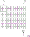
Fig. 8 is a plan view illustrating a display panel according to an exemplary embodiment of the present disclosure.
For convenience of explanation, a part of the configuration of the display panel 400 shown in fig. 8 is omitted. Referring to fig. 8, the first to sixth display areas DA1 to DA6 include first to sixth pixels PX1 to PX6, respectively. For example, the plurality of first, second, third, fourth, fifth, and sixth pixels PX1, PX2, PX3, PX4, PX5, and PX6 respectively along the tangential direction  Arranged in the first, second, third, fourth, fifth, and sixth display areas DA1, DA2, DA3, DA4, DA5, and DA6, for example, a plurality of first pixels PX1 may be arranged along a circumference of the first display area DA1, or the like. The first pixel PX1 to the sixth pixel PX6 haveThere are structures similar to each other, and thus, hereinafter, the first pixel PX1 and the second pixel PX2 will be described as representative examples.
In the present disclosure, circumferential rows and radial columns may be defined. The circumferential rows may be formed from a material that is oriented in a tangential direction The defined imaginary line is defined, and "r (distance from the center of the display panel)" may be constant at positions/coordinates on the same circumferential row. The radial array may consist of +.>
 The defined imaginary line defines, and +.>
 (angle to the x-axis) "may be constant at the same radial position/coordinate. As shown in fig. 8, the first pixel PX1 may be +_in the tangential direction in the first display area DA1>
 Arranged on one circumferential row, but they should not be limited thereto or thereby. That is, the first pixels PX1 may be arranged in two or more circumferential rows in the first
 display area DA 1. In other words, the first pixel PX1 may be +_in the tangential direction > And radial direction->
 Arranged in a radial matrix pattern. The second to sixth pixels PX2 to PX6 include pixels arranged in a radial matrix pattern in the second to sixth display areas DA2 to DA6, respectively.
Fig. 9A and 9B are views illustrating enlarged views of the first pixel PX1 and the second pixel PX2 illustrated in fig. 8 according to an exemplary embodiment of the present disclosure. Hereinafter, the first pixel PX1 and the second pixel PX2 will be described with reference to fig. 9A and 9B. The first to sixth pixels PX1 to PX6 have structures similar to each other, and thus, hereinafter, the first and second pixels PX1 and PX2 will be described as representative examples.
In the present exemplary embodiment, the first pixel area of the first pixel PX1 is larger than the second pixel area of the second pixel PX2. In the present disclosure, the term "area" used herein means a size defined when viewed in a plan view, and the term "pixel area" used herein means an area of a pixel. For example, when the first pixel PX1 is in the radial direction The width in the above direction is referred to as a first radial width Wr1, and the first pixel PX1 is +_in the tangential direction>
 The maximum width of the upper pixel PX is referred to as a first tangential width Wc1, and the second pixel PX2 is +_in the radial direction >
 The width in this direction is referred to as the second radial width Wr2, and the second pixel PX2 is tangential +.>
 When the maximum width is referred to as a second tangential width Wc2, at least one of the second radial width Wr2 and the second tangential width Wc2 may be smaller than the first radial width Wr1 and the first tangential width Wc1.
Each of the first and second pixels PX1 and PX2 includes a first subpixel SPX1, a second subpixel SPX2, and a third subpixel SPX3. The first, second and third sub-pixels SPX1, SPX2 and SPX3 are arranged in a tangential direction Above, they should not be limited thereto or thereby. That is, at least one of the sub-pixels SPX1 to SPX3 may be arranged to be +_in the radial direction>
 And overlap another sub-pixel of the sub-pixels SPX1 to SPX3.
The sub-pixels SPX1 to SPX3 may display one of primary colors, for example, red, green, and blue, respectively. The colors displayed by the sub-pixels SPX1 to SPX3 should not be limited to red, green, and blue, and the sub-pixels SPX1 to SPX3 may display a plurality of colors, for example, white or secondary primary colors of yellow, cyan, and magenta. Each of the first pixel PX1 and the second pixel PX2 includes two or four or more sub-pixels.
The areas of the first to third sub-pixels SPX1 to SPX3 of the second pixel PX2 may be smaller than the areas of the first to third sub-pixels SPX1 to SPX3 of the first pixel PX 1. In the present exemplary embodiment, the ratio between the areas of the first to third sub-pixels SPX1 to SPX3 of the second pixel PX2 and the areas of the first to third sub-pixels SPX1 to SPX3 of the first pixel PX1 may be substantially equal to the ratio between the area of the second pixel PX2 and the area of the first pixel PX 1.
Fig. 10A is a cross-sectional view illustrating the first subpixel SPX1 illustrated in fig. 9A, and fig. 10B is a cross-sectional view illustrating the first subpixel SPX1 according to an exemplary embodiment of the present disclosure.
Referring to fig. 10A, the display panel 400 includes a base substrate BS, a pixel circuit layer PC, a first insulating layer IL1, a lower electrode LE, an organic light emitting layer OL disposed on the lower electrode LE, an upper electrode UE disposed on the organic light emitting layer OL, and a second insulating layer IL2 disposed on the upper electrode UE.
In the present exemplary embodiment, the base substrate BS is transparent and includes a rigid glass material or a polymer having flexibility. The pixel circuit layer PC may be disposed on the entire area of the base substrate BS. The pixel circuit layer PC may include, for example, two or more transistors. The pixel circuit layer PC may include: a switching transistor turned on in response to a gate signal applied thereto to transmit a data voltage; and a driving transistor that supplies a driving current corresponding to the data voltage from the switching transistor to the organic light emitting layer OL.
The first insulating layer IL1 may be disposed on the entire area of the pixel circuit layer PC. The first insulating layer IL1 includes a contact hole formed through the first insulating layer IL1 to expose a portion of the pixel circuit layer PC. The first insulating layer IL1 has a single-layer structure or a multi-layer structure of an organic material or an inorganic material.
In the present exemplary embodiment, the lower electrode LE may be disposed on the first insulating layer IL 1. A portion of the lower electrode LE may be disposed in the contact hole to be in contact with the pixel circuit layer PC, and may independently receive a driving current from the pixel circuit layer PC.
The display panel 400 may further include a pixel defining layer PDL. The pixel defining layer PDL may be disposed on the lower electrode LE and the first insulating layer IL 1. The pixel defining layer PDL may cover an edge of the lower electrode LE and expose a portion of the lower electrode LE.
In the present exemplary embodiment, the organic light emitting layer OL may be disposed on the pixel defining layer PDL and the lower electrode LE. The organic light emitting layer OL may emit light. As an example, the organic light emitting layer OL may include a white organic light emitting layer generating white light.
The upper electrode UE may be disposed on the organic light emitting layer OL. The second insulating layer IL2 may be disposed on the upper electrode UE. The second insulating layer IL2 may encapsulate the organic light emitting layer OL. The second insulating layer IL2 may include, for example, a plurality of thin film encapsulation layers. The thin film encapsulation layer may include an organic layer and an inorganic layer alternately stacked on each other.
The display panel 400 may include a black matrix BM, a color filter CF, and an upper substrate US sequentially stacked on the second insulating layer IL 2. The color filter CF and the black matrix BM may be directly formed and stacked on the second insulating layer IL2 and disposed on a layer defined between the lower electrode LE and the base substrate BS. In the present exemplary embodiment, the first subpixel SPX1 is a red subpixel, and the color filter CF is a red color filter.
The black matrix BM may prevent transistors of the pixel circuit layer PC and lines disposed on the base substrate BS from being perceived. The black matrix BM and the color filter CF may prevent external light incident from the upper substrate US from being perceived by a user after being reflected.
The first sub-light emitting area SEA1 may be defined in the first sub-pixel SPX 1. The first sub-light emitting area SEA1 may be defined by a pixel defining layer PDL or a black matrix BM. For example, the first sub-light emitting region SEA1 may be defined to correspond to the lower electrode LE exposed by the pixel defining layer PDL or by the opening OP defined through the black matrix BM.
Each of the lower electrode LE and the upper electrode UE may include a conductive material. In more detail, each of the lower electrode LE and the upper electrode UE may be a transparent electrode, a semitransparent electrode, or an opaque electrode (or a reflective electrode). In addition, each of the lower electrode LE and the upper electrode UE may have a single-layer structure of a single material or a plurality of different materials, or a multi-layer structure of layers formed of different materials.
When each of the upper electrode UE and the lower electrode LE is a transparent electrode or a semitransparent electrode, each of the upper electrode UE and the lower electrode LE may include: for example Li, ca, liF/Ca, liF/Al, al, mg, baF, ba, ag, compounds thereof, or mixtures thereof (e.g., mixtures of Ag and Mg), each of which is optically thin; or transparent metal oxides (e.g., indium Tin Oxide (ITO), indium Zinc Oxide (IZO), zinc oxide (ZnO), indium Tin Zinc Oxide (ITZO)), mo, ti, etc. When each of the upper electrode UE and the lower electrode LE is a reflective electrode, each of the upper electrode UE and the lower electrode LE may include: such as Ag, mg, cu, al, pt, pd, au, ni, nd, ir, cr, li, ca, liF/Ca, liF/Al, mo, ti, compounds thereof, or mixtures thereof (e.g., mixtures of Ag and Mg), each of which is optically thick.
In the present exemplary embodiment, the first subpixel SPX1 may be of a rear surface emission type or a front surface emission type. In the case where the first subpixel SPX1 is of a rear surface light emitting type, the lower electrode LE may be a transparent or semi-transparent electrode, the upper electrode UE may be a reflective electrode, and red light may exit to the outside through the lower electrode LE. In the case where the first subpixel SPX1 is of a front surface light emitting type, the lower electrode LE may be a reflective electrode, the upper electrode UE may be a transparent or semitransparent electrode, and light may exit to the outside through the upper electrode UE.
In the present exemplary embodiment, the first subpixel SPX1 may have a non-inversion structure or an inversion structure. In the case where the first subpixel SPX1 has a non-inversion structure, the lower electrode LE is an anode, the upper electrode UE is a cathode, and the voltage applied to the lower electrode LE is higher than the voltage applied to the upper electrode UE. In contrast, in the case where the first subpixel SPX1 has the inversion structure, the lower electrode LE is a cathode, the upper electrode UE is an anode, and the voltage applied to the lower electrode LE is lower than the voltage applied to the upper electrode UE.
Referring to fig. 10B, the display panel 400 may not include the black matrix BM and the color filters CF. The display panel 400 may further include a polarizing plate POL disposed on the upper substrate US. The polarizing plate POL can effectively reduce reflection of external light. Although not shown in the drawings, the display panel 400 may further include a retardation plate interposed between the upper substrate US and the polarizing plate POL. The delay plate may comprise a lambda/4 delay plate or a lambda/2 delay plate.
In the present exemplary embodiment, the organic light emitting layer OL may include at least one of a red organic light emitting layer, a green organic light emitting layer, and a blue organic light emitting layer. The first subpixel SPX1 may be, for example, a red subpixel, and the organic light emitting layer OL may include a red organic light emitting layer.
Fig. 11A and 11B are plan views illustrating first and second pixels according to an exemplary embodiment of the present disclosure, and fig. 12A and 12B are cross-sectional views taken along lines I-I 'and II-II' shown in fig. 11A and 11B, respectively.
Referring to fig. 11A and 11B, each of the first to third sub-pixels SPX1 to SPX3 of the first and second pixels PX1 and PX2 may include a sub-light emitting region defined therein. In more detail, the first to third sub-emission areas SEA1 to SEA3 are defined in the first to third sub-pixels SPX1 to SPX3, respectively. In the present exemplary embodiment, the area of the light emitting region may be defined by the sub light emitting region of each pixel.
In more detail, the first to third sub-light emitting areas SEA1 to SEA3 of the first pixel PX1 may form a first light emitting area of the first pixel PX1, and a sum of areas of the first to third sub-light emitting areas SEA1 to SEA3 of the first pixel PX1 may be defined as an area of the first light emitting area. Similarly, the first to third sub-emission regions SEA1 to SEA3 of the second pixel PX2 may form a second emission region of the second pixel PX2, and the sum of the areas of the first to third sub-emission regions SEA1 to SEA3 of the second pixel PX2 may be defined as the area of the second emission region.
In the present exemplary embodiment, an inequality may be satisfied: (ES 1/PS 1) < (ES 2/PS 2). "PS1" denotes a first pixel area, "ES1" denotes an area of a first light emitting region of the first pixel PX1, "PS2" denotes a second pixel area, and "ES2" denotes an area of a second light emitting region of the second pixel PX 2. In other words, in the case of the ratio of the light emitting area to the pixel area, the second light emitting area ratio of the second pixel PX2 may be greater than the first light emitting area ratio of the first pixel PX 1.
Accordingly, the area difference between the first light emitting region and the second light emitting region is reduced, and thus the luminance difference caused by the difference between the first pixel area and the second pixel area can be reduced. Accordingly, the luminance of the first pixel PX1 and the second pixel PX2 becomes uniform.
Referring to fig. 12A and 12B, the first and second pixels PX1 and PX2 include first and second black matrices BM1 and BM2, respectively. The first black matrix BM1 overlaps the first pixel PX1 in the first direction DR1, and defines first to third sub-emission areas SEA1 to SEA3 of the first pixel PX 1. The second black matrix BM2 overlaps the second pixel PX2 in the first direction DR1, and defines first to third sub-emission areas SEA1 to SEA3 of the second pixel PX 2. In the present exemplary embodiment, the first black matrix BM1 has an area larger than that of the second black matrix BM2.
In the present exemplary embodiment, the radial direction of the first black matrix BM1 The first width is larger than the radial direction of the second black matrix BM2>
 A second width thereon. The first width of the first black matrix BM1 and the radial direction +.>
 The sum of the widths Lb1 and Lb2 of the portions facing each other corresponds such that the first sub-light emitting area SEA1 of the first pixel PX1 is disposed between the portions of the first
 black matrix BM 1. Similarly, the second width of the second black matrix BM2 is equal to the radial +_ of the second black matrix BM2> The sum of the widths Lb3 and Lb4 of the portions facing each other corresponds such that the first sub-light emitting area SEA1 of the second pixel PX2 is disposed between the portions of the second
 black matrix BM 2.
In the present exemplary embodiment, the tangential direction of the first black matrix BM1 The third width on the first and second black matrix BM2 is substantially equal to the tangential direction +.>
 A fourth width on the upper surface. The third width corresponds to the sum of the widths Lc1 to Lc4 of the portion of the first black matrix BM1 overlapping the imaginary line IML1 passing through the first pixel PX1 and substantially parallel to the tangential direction +.>
 Similarly, the fourth width corresponds to the sum of the widths Lc5 to Lc8 of the portion of the second black matrix BM2 overlapping the imaginary line IML2 passing through the second pixel PX2 and substantially parallel to the tangential direction >
 Further, the third width may be a first black disposed between adjacent ones of the first to third sub-pixels SPX1 to SPX3 of the first pixel PX1Tangential direction of matrix BM1 +.>
 The width of the upper (i.e., one of Lc1, lc2, lc3, and Lc 4), and the fourth width may be the tangential direction ∈ of the second black matrix BM2 disposed between the sub-pixels adjacent to each other among the first to third sub-pixels SPX1 to SPX3 of the second pixel PX2>
 Upper width (i.e., one of Lc5, lc6, lc7, and Lc 8).
As shown in fig. 12A and 12B, the first pixel PX1 includes a first pixel defining layer PDL1. The first pixel defining layer PDL1 defines first to third sub-emission areas SEA1 to SEA3 of the first pixel PX 1. In more detail, since only a portion of the organic light emitting layer OL corresponding to the lower electrode LE1 exposed by the first pixel defining layer PDL1 and not covered emits light, the first to third sub-light emitting areas SEA1 to SEA3 may be defined to correspond to the lower electrode LE1 exposed by the first pixel defining layer PDL1 and not covered. In other words, the first pixel defining layer PDL1 may expose the lower electrode LE1 through the first light emitting area.
Similarly, the second pixel PX2 includes a second pixel defining layer PDL2. The second pixel defining layer PDL2 defines first to third sub-emission areas SEA1 to SEA3 of the second pixel PX 2. In more detail, since only a portion of the organic light emitting layer OL corresponding to the lower electrode LE2 exposed by the second pixel defining layer PDL2 and not covered emits light, the first to third sub-light emitting areas SEA1 to SEA3 may be defined to correspond to the lower electrode LE2 exposed by the second pixel defining layer PDL2 and not covered. In other words, the second pixel defining layer PDL2 may expose the lower electrode LE2 through the second light emitting area.
In the present exemplary embodiment, the first pixel defining layer PDL1 has an area larger than that of the second pixel defining layer PDL 2. Further, the ratio of the area of the first pixel defining layer PDL1 to the first pixel area may be larger than the ratio of the area of the second pixel defining layer PDL2 to the second pixel area. Accordingly, the second light emitting area ratio of the second pixel PX2 may be greater than the first light emitting area ratio of the first pixel PX 1.
Accordingly, an area difference between the light emitting area of the organic light emitting layer OL of the first pixel PX1 and the light emitting area of the organic light emitting layer OL of the second pixel PX2 is reduced, and thus a luminance difference caused by the difference between the first pixel area and the second pixel area can be reduced. Accordingly, the luminance of the first pixel PX1 and the second pixel PX2 becomes uniform.
Fig. 13A and 13B are plan views illustrating first and second pixels according to an exemplary embodiment of the present disclosure. Referring to fig. 13A and 13B, the third width and the fourth width may be different from each other. For example, the third width may be greater than the fourth width. Further, the first width may be greater than the second width.
In more detail, the sum of the widths Lc1 to Lc4 of the portion of the first black matrix BM1 may be greater than the sum of the widths Lc5 to Lc8 of the portion of the second black matrix BM 2. Further, the first black matrix BM1 disposed between the sub-pixels SPX1 to SPX3 adjacent to each other is in the tangential direction  The width of the upper portion (i.e., one of Lc1, lc2, lc3, and Lc 4) may be greater than that of the second black matrix BM2 disposed between the sub-pixels SPX1 to SPX3 adjacent to each other in the tangential direction +.>
 Upper width (i.e., one of Lc5, lc6, lc7, and Lc 8).
Fig. 14 is an enlarged view illustrating a first pixel according to an exemplary embodiment of the present disclosure.
Referring to fig. 14, a portion of the second sub-light emitting area SEA2 of the first pixel PX1 may be in the tangential direction And overlap the first sub-emission area SEA1 and the third sub-emission area SEA3 of the
 first pixel PX 1. The first to third sub-emission regions SEA1 to SEA3 are in tangential direction +.> Arranged in a zigzag fashion. In more detail, the first minimum distance dc1, which is the smallest between the first sub-light emitting area SEA1 and the center of the
 display panel 400, may be different from the second minimum distance dc2, which is the smallest between the second sub-light emitting area SEA2 and the center of the display panel 400. The first minimum distance dc1 may be greater than the second minimum distance dc2 and equal to a third minimum distance dc3 that is the smallest between the third sub-light emitting area SEA3 and the center of the display panel 400.
Fig. 15 is a plan view illustrating a display panel according to an exemplary embodiment of the present disclosure, and fig. 16 is an enlarged view illustrating first and second display lines illustrated in fig. 15.
In fig. 15, the display panel 400 has a structure and function similar to those of the display panel 400 shown in fig. 13, and thus different features of the additional display lines will be described in detail. Referring to fig. 15, the display panel 400 may further include display lines. The display lines may include first to sixth display lines Ld1 to Ld6 connected to the first to sixth pixels PX1 to PX6, respectively.
In detail, each of the first to sixth display lines Ld1 to Ld6 includes at least one of a gate line transmitting a gate signal, a data line transmitting a data voltage, and a control line transmitting a light emission control signal. The first display line Ld1 to the sixth display line Ld6 are substantially parallel to the radial direction And arranged in tangential direction +.>
 And (3) upper part. The first display line Ld1 to the sixth display line Ld6 are similar to each other, and thus the first display line Ld1 and the second display line Ld2 will be described in detail as representative examples. The description of the first display line Ld1 and the second display line Ld2 may be similarly applied to other display lines.
Referring to fig. 16, the first display line Ld1 includes a gate line and a data line, and a gate signal and a data voltage are applied to the first pixel PX1. The first pixel PX1 displays an image in response to the gate signal and the data voltage from the first display line Ld 1.
The first display line Ld1 is arranged in the tangential direction Between two first pixels PX1 adjacent to each other. In the present exemplary embodiment, the first display line Ld1 is +_in the radial direction>
 Spaced apart from the second pixel PX2, and in the tangential direction +.>
 And does not overlap the second pixel PX2. In other words, the first display line Ld1 may not be disposed between the second to sixth pixels PX2 to
 PX 6. In the present exemplary embodiment, the first display line Ld1 may be +_in the radial direction> And overlaps the second pixel PX2.
In the present exemplary embodiment, the second display line Ld2 includes a gate line and a data line, and a gate signal and a data voltage are applied to the second pixel PX2. The second pixel PX2 displays an image in response to the gate signal and the data voltage from the second display line Ld 2.
The second display line Ld2 is arranged in the tangential direction Between two second pixels PX2 adjacent to each other, disposed in the tangential direction +.>
 Between two first pixels PX1 adjacent to each other. In the present exemplary embodiment, the second display line Ld2 is +_in the radial direction>
 Spaced apart from the third pixel PX3, and in the tangential direction +.>
 And does not overlap the
 third pixel PX 3. In other words, the second display line Ld2 may not be disposed between the third to sixth pixels PX3 to PX 6. In the present exemplary embodiment, the second display line Ld2 may be +_in the radial direction > And overlaps the
 third pixel PX 3.
In the above structure, in the tangential direction Width of non-display area NDA2 between second pixels PX2 adjacent to each other, and +_in tangential direction>
 The width of the non-display area NDA3 between the third pixels PX3 adjacent to each other is reduced, and the areas of the second pixel area and the third pixel area are increased. Accordingly, the pixel area difference between the first to third pixels PX1 to PX3 is reduced, and the luminance of the first to third pixels PX1 to PX3 becomes uniform.
Fig. 17 is a plan view illustrating a display panel according to an exemplary embodiment of the present disclosure, and fig. 18 is an enlarged view illustrating first and second display lines illustrated in fig. 17.
In fig. 17, the display panel 400 has a structure and function similar to those of the display panel 400 shown in fig. 7A, and thus different features of the additional display lines will be described in detail. Referring to fig. 17, the display panel 400 may further include display lines.
In detail, the display lines include first to sixth gate lines GL1 to GL6, and first to k-th data lines DL1 to DLk. The first to sixth gate lines GL1 to GL6 are connected to the first to sixth pixels PX1 to PX6, respectively. First image Each of the pixels PX1 to PX6 is arranged in the tangential direction with the mark "k Corresponding to the first to kth data lines DL1 to DLk.
The first to sixth gate lines GL1 to GL6 are substantially parallel to the tangential direction And in the radial direction->
 And (3) upper arrangement. The first to kth data lines DL1 to DLk are substantially parallel to the radial direction +.>
 And in tangential direction +.>
 And (3) upper arrangement. Since the first to sixth gate lines GL1 to GL6 are similar to each other, the first and second gate lines GL1 and GL2 will be described in detail as a representative example. The descriptions of the first and second gate lines GL1 and GL2 may be similarly applied to other gate lines. Further, the first to kth data lines DL1 to DLk are similar to each other, and thus the first data line DL1 will be described as a representative example. The description of the first data line DL1 may be similarly applied to other data lines.
Referring to fig. 18, the first gate line GL1 transmits a first gate signal, and the first data line DL1 transmits a data voltage. The first pixel PX1_1 displays an image in response to the first gate signal supplied through the first gate line GL1 and the data voltage supplied through the first data line DL 1.
The first data line DL1 is arranged in the tangential direction  Between two first pixels Px1_1 and Px1_k adjacent to each other and disposed in the tangential directionTo->
 Between two second pixels PX2_1 and PX2_k adjacent to each other. The first gate line GL1 is disposed between the first pixels PX1_1 to PX1_k and the second pixels PX2_1 to PX 2_k.
Similarly, the second gate line GL2 transmits a second gate signal, and the first data line DL1 transmits a data voltage. The second pixel PX2_1 displays an image in response to the second gate signal supplied through the second gate line GL2 and the data voltage supplied through the first data line DL 1. The second gate line GL2 is disposed between the second pixels PX2_1 to PX2_k and the third pixels PX3_1 to PX 3_k.
Fig. 19 is a cross-sectional view illustrating a display module according to an exemplary embodiment of the present disclosure, fig. 20 is a plan view illustrating the display panel illustrated in fig. 19, and fig. 21 is a rear view illustrating the display panel illustrated in fig. 19.
Referring to fig. 19, the first display area DA1 includes a first portion DA11, a second portion DA12, and a curved portion DA13 connecting the first portion DA11 and the second portion DA 12. The curved portion DA13 is curved such that the first portion DA11 is folded downward. For example, the first portion DA11 may be connected to the second portion DA12, and may be folded away from the second portion DA12 toward the housing 500 such that the first portion DA11 and the second portion DA12 face each other in the first direction DR 1. In other words, the first portion DA11 is folded to allow the second portion DA12 to be interposed between the window member 300 and the first portion DA 11.
Referring to fig. 19, 20 and 21, the display surface of the second portion DA12 faces the lower surface 301 of the window member 300. The display surface of the first portion DA11 faces the upper surface of the housing 500. In other words, the lower surface of the first portion DA11 may be opposite to the lower surface of the window member 300.
In the present exemplary embodiment, the display module 200 may further include a flexible printed circuit board 201 and a display printed circuit board 205. The flexible printed circuit board 201 connects the display panel 400 and the display printed circuit board 205. One end of the flexible printed circuit board 201 is connected to an edge of the first portion DA11, and the other end of the flexible printed circuit board 201 is connected to the display printed circuit board 205. The connection pads are provided at the edges of the first portion DA 11. The connection pads connect the wires of the display panel 400 to the flexible printed circuit board 201.
The second portion DA12 is disposed between the flexible printed circuit board 201 and the window member 300, and between the display printed circuit board 205 and the window member 300.
Since the flexible printed circuit board 201 is connected to the display panel 400 through the pad portion provided on the first portion DA11, a black matrix for preventing the pad portion from being perceived is not required. Accordingly, the bezel width of the display panel 400 can be effectively reduced.
Fig. 22 is a cross-sectional view illustrating a display module according to an exemplary embodiment of the present disclosure.
In fig. 22, the display module 200 has a structure and function similar to those of the display module 200 shown in fig. 3, and thus different features of the additional touch module 800 will be described in detail. Referring to fig. 22, the display module 200 includes a touch module 800.
In detail, the touch module 800 is disposed between the window member 300 and the display panel 400. In the present exemplary embodiment, the touch module 800 includes a first touch area TA1 and a second touch area TA2 that are distinguished from each other in a horizontal direction. The first touch area TA1 and the second touch area TA2 are disposed under the first window area WA1 and the second window area WA2, respectively. The first touch area TA1 senses a first external input applied to the first window area WA1 to generate a touch signal, and the second touch area TA2 senses a second external input applied to the second window area WA2 to generate a touch signal.
As described above, the second thickness of the second window area WA2 is greater than the first thickness of the first window area WA 1. Therefore, the intensity of the second external input applied to the second touch area TA2 after passing through the second window area WA2 may be smaller than the intensity of the first external input applied to the first touch area TA1 after passing through the first window area WA 1.
In the present exemplary embodiment, the sensitivity of the second touch area TA2 may be higher than that of the first touch area TA 1. Accordingly, the touch module 800 may compensate for the intensity difference between the first external input and the second external input, and thus the touch module 800 may accurately sense the external input. In order to increase the sensitivity of the second touch area TA2 to be higher than that of the first touch area TA1, the size of the touch electrodes, the number of touch electrodes per unit area, the distance between the touch electrodes, the processing of the touch signal and the sensing signal may be controlled.
Fig. 23A is an enlarged cross-sectional view illustrating the touch module shown in fig. 22, and fig. 23B to 23D are plan views illustrating the touch module according to an exemplary embodiment of the present disclosure.
Referring to fig. 23A, the touch module 800 includes a base layer 810 and touch electrodes disposed on the base layer 810. In the present exemplary embodiment, the touch electrodes include a first touch electrode TE1 disposed in the first touch area TA1, and a second touch electrode TE2 disposed in the second touch area TA 2.
The touch module 800 may be, for example, a self-capacitance type or a mutual capacitance type. The first and second touch electrodes TE1 and TE2 may be deformed, arranged, and connected corresponding to the type of the touch module 800.
In the present exemplary embodiment, the size of the first touch electrode TE1 may be larger than the size of the second touch electrode TE 2. The third length L3 of the first touch electrode TE1 in the horizontal direction may be greater than the fourth length L4 of the second touch electrode TE2 in the horizontal direction.
Referring to fig. 23B, the first electrode area of the first touch electrode TE1 may be greater than the second electrode area of the second touch electrode TE2, and the distance between two first touch electrodes TE1 adjacent to each other may be substantially equal to the distance between two second touch electrodes TE2 adjacent to each other. In the present exemplary embodiment, each of the first and second touch electrodes TE1 and TE2 may have a substantially square shape.
In the present exemplary embodiment, the number of the second touch electrodes TE2 per unit area may be greater than the number of the first touch electrodes TE1 per unit area. Accordingly, the intensity difference between the first external input and the second external input may be compensated, and thus the touch module 800 may accurately sense the external input.
Referring to fig. 23C, the third distance P3 in the horizontal direction between the two first touch electrodes TE1 adjacent to each other may be greater than the fourth distance P4 in the horizontal direction between the two second touch electrodes TE2 adjacent to each other, and the first electrode area of the first touch electrode TE1 and the second electrode area of the second touch electrode TE2 may be equal to each other, but they should not be limited thereto or thereby. That is, the third distance P3 and the fourth distance P4 may be equal to each other. Accordingly, the strength of a fringe field (fringe field) formed between the second touch electrodes TE2 adjacent to each other may be greater than the strength of a fringe field formed between the first touch electrodes TE1 adjacent to each other. Accordingly, the intensity difference between the first external input and the second external input may be compensated, and thus the accuracy of the touch module 800 with respect to the external input may be improved.
Referring to fig. 23D, the first sensing signal DS1 is applied to the first touch area TA1. The first sensing signal DS1 may be a signal supplied to the first touch electrode TE1 to sense a first external input. Similarly, the second sensing signal DS2 is applied to the second touch area TA2. The second sensing signal DS2 may be a signal supplied to the second touch electrode TE2 to sense a second external input.
In the present exemplary embodiment, the touch module 800 may further include a sensing controller 830. The sensing controller 830 is disposed on one of the base layer 810, the display printed circuit board 205 (see fig. 19), or the electronic module substrate 110 (see fig. 19). The sensing controller 830 includes a first sub-sensing controller 831 and a second sub-sensing controller 832. The first and second sub-sensing controllers 831 and 832 generate the first and second sensing signals DS1 and DS2, respectively, and receive the first and second touch signals TS1 and TS2, respectively.
The first touch electrode TE1 of the first touch area TA1 outputs the first touch signal TS1 in response to the first sensing signal DS1, and the second touch electrode TE2 of the second touch area TA2 outputs the second touch signal TS2 in response to the second sensing signal DS 2. The sensing controller 830 calculates coordinates of an external input using the first touch signal TS1 and the second touch signal TS2.
The first and second sub-sensing controllers 831 and 832 may generate the first and/or second sensing signals DS1 and DS2 to have different intensities such that an intensity difference between the first and second external inputs is compensated. For example, since the intensity of the first external input is greater than the intensity of the second external input, the first sub-sensing controller 831 and the second sub-sensing controller 832 may increase the intensity of the second sensing signal DS 2. Accordingly, the intensity difference between the first external input and the second external input may be compensated for, and thus the accuracy of the touch module 800 with respect to the external input may be improved.
The present disclosure should not be limited thereto or thereby. In the present exemplary embodiment, the intensity of the first sensing signal DS1 and the intensity of the second sensing signal DS2 may be the same as each other, and the first sub-sensing controller 831 and the second sub-sensing controller 832 may process the first touch signal TS1 and the second touch signal TS2 based on an intensity difference between the first external input and the second external input. Thus, the intensity difference between the first external input and the second external input can be compensated.
Fig. 24A is a view illustrating a touch electrode according to an exemplary embodiment of the present disclosure, fig. 24B is an enlarged view illustrating a region "a" illustrated in fig. 24A, and fig. 24C is an enlarged cross-sectional view taken along a line III-III' illustrated in fig. 24B.
Referring to fig. 24A, the first touch area TA1 includes column touch electrodes CTE and row touch electrodes RTE. The column touch electrodes CTE extend in the second direction DR2 and the row touch electrodes RTE extend in the third direction DR 3. The row touch electrodes RTE are CTE-insulated from the column touch electrodes. The external input is sensed based on the mutual capacitance between the row touch electrodes RTE and the column touch electrodes CTE.
The column touch electrode CTE includes first sensor patterns TSP1 arranged in the second direction DR2, and first connection patterns TLP1 connecting two first sensor patterns of the first sensor patterns TSP1 adjacent to each other in the second direction DR 2. The first sensor pattern TSP1 may be integrally formed with the first connection pattern TLP1.
The row touch electrode RTE includes the second sensor patterns TSP2 arranged in the third direction DR3, and the second connection pattern TLP2 connecting two of the second sensor patterns TSP2 adjacent to each other in the third direction DR 3. The second sensor pattern TSP2 may be integrally formed with the second connection pattern TLP2. The second connection pattern TLP2 is insulated from the first connection pattern TLP1 when crossing the first connection pattern TLP1.
Referring to fig. 24B, each of the first and second sensor patterns TSP1 and TSP2 may have a mesh shape. In more detail, the conductive portions CP each having a width in the range of several hundred nanometers to several hundred micrometers may cross each other to form a mesh shape. The opening OP may be defined between the conductive portions CP. The transmittance and the resistance of the first and second sensor patterns TSP1 and TSP2 may be determined according to the size of the opening or the width of the conductive portion CP.
Referring to fig. 24C, the touch module 800 includes a buffer layer 841, an intermediate layer 842, and a cover layer 843 sequentially stacked on a base layer 810. Each of the first and second sensor patterns TSP1 and TSP2 includes first and second conductive layers CL1 and CL2.
Each of the first conductive layer CL1 and the second conductive layer CL2 may include: such as Ag, mg, al, pt, pd, au, ni, nd, ir, cr, li, ca, liF/Ca, liF/Al, mo, ti, compounds thereof, or mixtures thereof. Each of the first and second conductive layers CL1 and CL2 may include a transparent metal oxide, for example, indium Tin Oxide (ITO), indium Zinc Oxide (IZO), zinc oxide (ZnO), indium Tin Zinc Oxide (ITZO), mo, ti, and the like.
The first conductive layer CL1 is disposed between the buffer layer 841 and the intermediate layer 842, and the second conductive layer CL2 is disposed between the intermediate layer 842 and the cover layer 843. Second conductive layer CL2 is connected to first conductive layer CL1 through a contact hole formed through intermediate layer 842.
Fig. 25A is a view illustrating a touch area according to an exemplary embodiment of the present disclosure.
Referring to fig. 25A, the touch module 800 includes a first touch area TA1, a second touch area TA2, and a third touch area TA3. The touch module 800 has an elliptical shape, for example, a substantially circular shape. The first to third touch areas TA1 to TA3 are defined to correspond to the shape of the touch module 800.
In more detail, the first to third touch areas TA1 to TA3 are in the radial direction Arranged sequentially. The boundaries of the first to third touch areas TA1 to TA3 have an elliptical shape or a substantially circular shape. Each of the first touch area TA1 and the second touch area TA2 has a circular shape, and the third touch area TA3 has a circular shape when viewed in a plan view. The circumferences of the first to third touch areas TA1 to TA3 become smaller in the order of the first, second and third touch areas TA1, TA2 and
 TA 3.
Fig. 25B is a plan view illustrating a touch module according to an exemplary embodiment of the present disclosure.
For convenience of explanation, some parts of the touch module are omitted in fig. 25B. Referring to fig. 25B, the touch module 800 may further include a touch line. The touch lines may include, for example, a first touch line Lt1, a second touch line Lt2, and a third touch line Lt3 connected to the first touch electrode TE1, the second touch electrode TE2, and the third touch electrode TE3, respectively.
In the present exemplary embodiment, each of the first to third touch electrodes TE1 to TE3 includes a touch electrode that is substantially parallel to the radial direction Is substantially parallel to the tangential direction +. >
 Is provided.
The first touch line Lt1 to the third touch line Lt3 are substantially parallel to the radial direction And in tangential direction
 And (3) upper arrangement. The first touch line Lt1 to the third touch line Lt3 are similar to each other, and thus the first touch line Lt1 and the second touch line Lt2 will be described as representative examples. The description of the first touch line Lt1 and the second touch line Lt2 may be similarly applied to the third touch line Lt3.
In the present exemplary embodiment, the first touch line Lt1 applies a sensing signal to the first touch electrode TE1 and receives a touch signal from the first touch electrode TE 1. In response to the sensing signal from the first touch line Lt1, the first touch electrode TE1 outputs a touch signal corresponding to the self capacitance changed by the external input.
The first touch line Lt1 is arranged in the tangential direction Between two first touch electrodes TE1 adjacent to each other. In the present exemplary embodiment, the first touch line Lt1 is +_in the radial direction>
 Spaced apart from the second touch electrode TE2 and in tangential direction +.>
 And does not overlap the second
 touch electrode TE 2. In other words, the first touch line Lt1 may not be disposed between the second touch electrode TE2 and the third touch electrode TE 3.
In the present exemplary embodiment, the second touch line Lt2 applies a sensing signal to the second touch electrode TE2 and receives a touch signal from the second touch electrode TE 2. In response to the sensing signal from the second touch line Lt2, the second touch electrode TE2 outputs a touch signal corresponding to the self capacitance changed by the external input.
The second touch line Lt2 is arranged in the tangential direction Between two second touch electrodes TE2 adjacent to each other. In the present exemplary embodiment, the second touch line Lt2 is +_in the radial direction>
 Spaced apart from the third touch electrode TE3 and in tangential direction +.>
 And does not overlap the third
 touch electrode TE 3. In other words, the second touch line Lt2 may not be disposed between the second touch electrode TE2 and the third touch electrode TE 3. In the present exemplary embodiment, the first touch line Lt1 is +_in the radial direction> And overlap the second
 touch electrode TE 2.
In the above structure, in the tangential direction The width of the non-touch area NTA2 between the two second touch electrodes TE2 adjacent to each other may be reduced. Accordingly, the resolution and sensitivity of the
 touch module 800 may be improved. Similarly, the +.in tangential direction can be reduced> The width of the non-touch area NTA3 between the two third touch electrodes TE3 adjacent to each other. Accordingly, the sensitivity of the
 touch module 800 may be improved.
Fig. 26 is a cross-sectional view illustrating an electronic timepiece 1000 according to an exemplary embodiment of the disclosure.
Referring to fig. 26, the electronic timepiece 1000 includes a joint sensing sensor 610, a crown sensor 620, and a crown 630.
The crown sensor 620 is disposed in the housing 500. The crown sensor 620 is disposed at a sidewall of the case 500 facing the coupling hole. Crown sensor 620 is in contact with the other end of crown shaft 631 or is disposed adjacent to the other end of crown shaft 631. The crown sensor 620 senses rotation or movement of the crown shaft 631 in a horizontal direction or senses a position of the crown shaft 631 to output a crown signal. As an example, the electronic module substrate 110 controls the display module 200 using the crown signal. The user rotates the crown 630 or moves the crown 630 in a horizontal direction to control the display module 200.
The coupling sensing sensor 610 is disposed in the housing 500. The coupling sensing sensor 610 is disposed between the housing 500 and the strap STR. The link sensing sensor 610 is in contact with or disposed adjacent to the strap STR. The coupling sensing sensor 610 senses whether the display module 200 is coupled to the coupling space of the strap STR and generates a coupling signal. The coupling sensing sensor 610 may be, for example, a pressure sensor, and senses a pressure applied thereto by the display module 200 to generate a coupling signal when the display module 200 is coupled to the strap STR. However, according to an embodiment, the coupling sensing sensor 610 may include a proximity sensor or an infrared sensor.
The electronic module substrate 110 may control the display module 200 using the coupling signal.
Fig. 27 is a cross-sectional view illustrating a window member according to an exemplary embodiment of the present disclosure.
The window member 300 according to the present exemplary embodiment may have a variable curvature. The curvature of the window member 300 may vary in the horizontal direction. In more detail, when the radii of curvature of the first, second, and third window areas WA1, WA2, and WA3 are referred to as a first radius of curvature r1, a second radius of curvature r2, and a third radius of curvature r3, respectively, the first, second, and third radii of curvature r1, r2, and r3 satisfy the following relationship: r1< r2< r3. Accordingly, the difference between the first to third thicknesses of the first to third window areas WA1 to WA3 is reduced, and the image is effectively prevented from being distorted by the window member 300. Accordingly, the display quality of the display module 200 may be improved. Further, the first radius of curvature r1, the second radius of curvature r2, and the third radius of curvature r3 may satisfy the following relationship: r1> r2> r3.
In the present exemplary embodiment, the window member 300 includes a plurality of lens layers to prevent distortion of an image. The window member 300 includes, for example, a concave lens layer having a concave lens shape, and a convex lens layer having a convex lens shape. The window member 300 has a structure in which concave lens layers and convex lens layers are alternately stacked on each other. Of the lens layers, at least one lens layer has a refractive index different from that of the other lens layers.
Fig. 28 is a cross-sectional view illustrating a window member 300 according to an exemplary embodiment of the present disclosure.
Referring to fig. 28, the window member 300 may further include an extension portion 302 extending from the first window area WA 1. The extension portion 302 extends to the display panel 400 and defines a panel space PS. A panel space PS is defined below the lower surface 301 of the window member 300.
The window member 300 is coupled to the case 500, and the display module 200 is disposed in the coupling space CS with STR.
Fig. 29A to 29C are cross-sectional views illustrating an electronic timepiece according to an exemplary embodiment of the present disclosure.
Referring to fig. 29A, the curvature of the upper surface of the window member 305 may be smaller than the curvature of the upper surface USS of the strap STR. Referring to fig. 29B, the curvature of the upper surface of window member 306 may be equal to the curvature of the upper surface USS of strap STR. Referring to fig. 29C, the curvature of the upper surface of the window member 307 may be greater than the curvature of the upper surface USS of the strap STR.
The electronic timepiece 1000 provides the user with an image having improved three-dimensional effect, immersion (or immersion) and image fidelity according to the curvature of the upper surface of the window member 300.
Fig. 30A and 30B are plan views illustrating an electronic timepiece according to an exemplary embodiment of the present disclosure.
Referring to fig. 30A, the band STR includes a first sub-band STR1 and a second sub-band STR2. The first and second sub-bands STR1 and STR2 are substantially symmetrical with respect to the origin with respect to the center of the window member 300. The first and second sub-bands STR1 and STR2 extend in opposite directions such that the window member 300 is disposed between the first and second sub-bands STR1 and STR2.
Referring to fig. 30B, the first and second sub-bands STR1 and STR2 are symmetrical to each other with respect to an imaginary line IML intersecting the center of the window member 300 and parallel to the horizontal direction.
Fig. 31 is an exploded perspective view illustrating an electronic timepiece according to an exemplary embodiment of the present disclosure.
Referring to fig. 31, the display module 200 may be separated from the strap STR as described above. Among the various display modules 200 and STRs, a user may select a display module 200 and a STR according to functions and designs of the display module 200 and STR, and combine the selected display module 200 and the selected STR to use the electronic watch for a specific purpose, use, or preference.
Fig. 32 is a plan view illustrating a display area according to an exemplary embodiment of the present disclosure, and fig. 33 is an enlarged view illustrating the display area illustrated in fig. 32.
Referring to fig. 32, the display region may have a polygonal shape.
For example, in the display region, the j-th display region DAj and the (j+1) -th display region daj+1 may have a rectangular shape including paired sides parallel to the second direction DR2 and the third direction DR3, respectively. The second direction DR2 and the third direction DR3 are substantially parallel to the planar surface. The j-th display area DAj may surround the (j+1) -th display area daj+ 1. The boundaries of the j-th display region DAj and the (j+1) -th display region daj+1 may be substantially parallel to the second direction DR2 or the third direction DR3.
Referring to fig. 33, the j-th display area DAj includes the j-th pixel PXj, and the (j+1) -th display area daj+1 includes the (j+1) -th pixel pxj+ 1. The j-th pixel PXj and the (j+1) -th pixel pxj+1 may have a rectangular shape including pairs of sides parallel to the second and third directions DR2 and DR3, respectively.
When the length of the side of the jth pixel PXj parallel to the third direction DR3 is referred to as a jth side length Lj, the length of the side of the (j+1) th pixel pxj+1 parallel to the third direction DR3 is referred to as a (j+1) th side length lj+1, the jth pixel PX arranged in the third direction DR3When the number of j is referred to as "M" and the number of (j+1) th pixels pxj+1 arranged in the third direction DR3 is referred to as "N", the equation is satisfied: (M and N are natural numbers). For example, when the j-th side length Lj is 1 and the (j+1) -th side length lj+1 is 0.8, (M, N) satisfying the equation may be (8, 10) or (12, 15). Since the j-th pixel PXj and the (j+1) -th pixel pxj+1 satisfy the equation, the opposite boundary BL of the j-th display area DAj and the (j+1) -th display area daj+1 may be substantially parallel to the second direction DR2.
Fig. 34A to 34E are plan views illustrating sub-pixels according to an exemplary embodiment of the present disclosure.
Referring to fig. 34A, the pixels PX are arranged in a matrix form along the second direction DR2 and the third direction DR3. Each of the pixels PX includes a red sub-pixel R, a green sub-pixel G, and a blue sub-pixel B. Each of the red, green, and blue sub-pixels R, G, and B has a rectangular shape including sides substantially parallel to the second and third directions DR2 and DR3. The red, green, and blue sub-pixels R, G, and B are sequentially arranged in the third direction DR3.
Referring to fig. 34B, the display panel 400 includes: the first and second logic pixels LP1 and LP2, wherein the first logic pixel LP1 is configured to include a red sub-pixel R and a green sub-pixel G arranged in the third direction DR3, and the second logic pixel LP2 is configured to include a blue sub-pixel B and a green sub-pixel G arranged in the third direction DR 3. The first and second logic pixels LP1 and LP2 are alternately arranged with each other along the second and third directions DR2 and DR 3.
Referring to fig. 34C, the pixels PX are arranged in a matrix form along the second direction DR2 and the third direction DR 3. Each of the pixels PX includes a red sub-pixel R, a green sub-pixel G, and a blue sub-pixel B. The red and green sub-pixels R and G are arranged in the second direction DR 2. The blue subpixel B is arranged to be spaced apart from the red subpixel R and the green subpixel G in the third direction DR 3.
Referring to fig. 34D, the display panel 400 includes: the first and second logic pixels LP1 and LP2, wherein the first logic pixel LP1 is configured to include a red sub-pixel R and a green sub-pixel G arranged in the fourth direction DR4, and the second logic pixel LP2 is configured to include a blue sub-pixel B and a green sub-pixel G arranged in the fourth direction DR4. The fourth direction DR4 may be a direction not parallel to at least one side of the display panel 400 or all sides of the display panel 400. The first and second logic pixels LP1 and LP2 are alternately arranged in the fifth direction DR 5. The fifth direction DR5 is substantially perpendicular to the fourth direction DR4.
Referring to fig. 34E, each of the red, green, and blue sub-pixels R, G, and B has a hexagonal shape including three pairs of sides respectively parallel to the third, fourth, and fifth directions DR3, DR4, and DR5. Each of the angle between the third direction DR3 and the fourth direction DR4 and the angle between the third direction DR3 and the fifth direction DR5 is about 60 degrees. The red, green, and blue sub-pixels R, G, and B are arranged in a matrix form along the third and fourth directions DR3 and DR 4.
By way of summary and review, according to an embodiment, a display module includes: a window member including a first window region having a first thickness and a second window region having a second thickness greater than the first thickness; and a display panel having a first display region overlapping the first window region in a thickness direction and including first pixels, and a second display region overlapping the second window region in the thickness direction and including second pixels. The second pixel has a second pixel area smaller than the first pixel area of the first pixel, and the pixels are arranged along the curved surface of the window member such that the image is not distorted by the curved surface of the window member. Thus, the display quality of the image displayed in the display panel can be improved.
Exemplary embodiments have been disclosed herein and, although specific terms are employed, they are used and are to be interpreted in a generic and descriptive sense only and not for purpose of limitation. In some cases, as will be apparent to one of ordinary skill in the art at the time of filing this application, features, characteristics, and/or elements described in connection with a particular embodiment may be used alone or in combination with features, characteristics, and/or elements described in connection with other embodiments unless explicitly stated otherwise. It will be understood by those skilled in the art that various changes in form and details may be made therein without departing from the spirit and scope of the invention as set forth in the appended claims.
Claims (18)
1. A display module, comprising:
a window member comprising a first window region having a first thickness and a second window region having a second thickness greater than the first thickness, and an upper surface of the first window region and an upper surface of the second window region having a curvature that is not equal to zero; and
a display panel, comprising:
a first display region overlapping the first window region in a thickness direction and including a plurality of first light emitting pixels; and
A second display region overlapping the second window region in the thickness direction and including a plurality of second light emitting pixels, at least one of the plurality of second light emitting pixels having a second pixel area smaller than a first pixel area of at least one of the plurality of first light emitting pixels,
wherein a first distance in a horizontal direction perpendicular to the thickness direction between first light emitting pixels adjacent to each other among the plurality of first light emitting pixels is greater than or equal to a second distance in the horizontal direction between second light emitting pixels adjacent to each other among the plurality of second light emitting pixels, an
Wherein the first and second light emitting pixels satisfy inequality (ES 1/PS 1) < (ES 2/PS 2),
wherein the PS1 represents the first pixel area, the ES1 represents an area of a first light emitting region of at least one of the plurality of first light emitting pixels, the PS2 represents the second pixel area, and the ES2 represents an area of a second light emitting region of at least one of the plurality of second light emitting pixels.
2. The display module of claim 1, wherein:
the window member also includes a third window region having a third thickness greater than the second thickness, an
The display panel further includes a third display region overlapping the third window region in the thickness direction and having a plurality of third light emitting pixels, the second pixel area being larger than a third pixel area of at least one of the plurality of third light emitting pixels.
3. The display module of claim 2, wherein the second display region is between the first display region and the third display region to connect the first display region to the third display region when viewed in plan view.
4. The display module of claim 1, wherein the display panel further comprises a first pixel defining layer exposing the lower electrode of at least one of the plurality of first light emitting pixels to correspond to the first light emitting region and a second pixel defining layer exposing the lower electrode of at least one of the plurality of second light emitting pixels to correspond to the second light emitting region.
5. The display module of claim 1, wherein the display panel further comprises:
a first black matrix overlapping the plurality of first light emitting pixels in the thickness direction to define the first light emitting region; and
And a second black matrix overlapping the plurality of second light emitting pixels in the thickness direction to define the second light emitting region, the first black matrix having an area larger than an area of the second black matrix.
6. The display module of claim 1, wherein the window member has a circular shape or an elliptical shape when viewed in a plan view, the first display region is outside the second display region when viewed in a plan view, and a boundary of the first display region and the second display region has a circular shape or an elliptical shape.
7. The display module of claim 5, the first plurality of light emitting pixels and the second plurality of light emitting pixels being along a radial direction of a cylindrical coordinate system And tangential direction->
 Arranged in a matrix form.
8. The display module of claim 7, wherein the first black matrix is in the tangential direction The width in the tangential direction is larger than the part of the second black matrix>
 Upper width.
9. The display module of claim 7, wherein the first black matrix is in the radial direction The width of the upper layer is larger than the radial direction of a part of the second black matrix >
 Upper width.
10. The display module of claim 7, wherein each of the plurality of first light emitting pixels comprises a light emitting diode disposed in the tangential direction A first sub-pixel and a second sub-pixel on the substrate, and at least a part of a sub-light emitting area of the first sub-pixel is +.>
 Is not overlapped with at least a portion of the sub-light emitting region of the second sub-pixel.
11. The display module of claim 7, wherein the display panel further comprises a display surface substantially parallel to the radial direction A second display line arranged in the tangential direction in the plurality of first light emitting pixels>
 Between the first light-emitting pixels adjacent to each other, and in the tangential direction, arranged in the plurality of second light-emitting pixels>
 Between second light emitting pixels adjacent to each other, and the first display line is arranged in the tangential direction +.>
 Between the first light-emitting pixels adjacent to each other and in the radial direction +.>
 Spaced from the plurality of second light emitting pixels.
12. The display module of claim 1, further comprising a controller for receiving first input image data having information related to an image displayed in the first display area and second input image data having information related to an image displayed in the second display area,
Wherein the controller compensates for a gray value of at least one of the first input image data and the second input image data to compensate for a difference in brightness between the first light emitting pixel and the second light emitting pixel caused by an area difference between the first pixel area and the second pixel area.
13. The display module of claim 1, wherein a curvature of an upper surface of the first window region is different from a curvature of an upper surface of the second window region.
14. The display module of claim 1, wherein a length in the horizontal direction of at least one of the plurality of second light emitting pixels is less than a length in the horizontal direction of at least one of the plurality of first light emitting pixels.
15. The display module of claim 14, wherein a total number of the plurality of first light emitting pixels is less than a total number of the plurality of second light emitting pixels.
16. An electronic timepiece comprising:
a display panel including a first display area for displaying a first partial image in a first direction and a second display area for displaying a second partial image in the first direction;
A window member including an edge portion on the first display area for enlarging the first partial image by M1 times and a center portion on the second display area for enlarging the second partial image by M2 times, the window member having an upper surface that is convex in the first direction and has a curvature different from zero; and
a housing accommodating the display panel,
wherein the M2 is greater than the M1 and the first number of pixels per unit area in the first display area is less than the second number of pixels per unit area in the second display area,
wherein a first distance in a horizontal direction perpendicular to a thickness direction between first light emitting pixels adjacent to each other among the first light emitting pixels is greater than or equal to a second distance in the horizontal direction between second light emitting pixels adjacent to each other among the second light emitting pixels, and
wherein the first and second light emitting pixels satisfy inequality (ES 1/PS 1) < (ES 2/PS 2),
wherein the PS1 represents a first pixel area, the ES1 represents an area of a first light emitting region of at least one of the plurality of first light emitting pixels, the PS2 represents a second pixel area, and the ES2 represents an area of a second light emitting region of at least one of the plurality of second light emitting pixels.
17. The electronic timepiece of claim 16, wherein an equation is satisfied: PN 2/pn1=m2/M1,
wherein PN1 represents the first number of pixels per unit area of the first display area, and PN2 represents the second number of pixels per unit area of the second display area.
18. An electronic device, comprising:
a window member including an upper surface that is convex in a thickness direction in which an image is provided and has a curvature that is not equal to zero; and
a display panel including a first display region overlapping an edge portion of the upper surface in the thickness direction and having a plurality of first light emitting pixels, and a second display region overlapping a center portion of the upper surface in the thickness direction and having a plurality of second light emitting pixels, at least one of the plurality of second light emitting pixels having a second pixel area smaller than a first pixel area of at least one of the plurality of first light emitting pixels,
wherein a first distance in a horizontal direction perpendicular to the thickness direction between first light emitting pixels adjacent to each other among the plurality of first light emitting pixels is greater than or equal to a second distance in the horizontal direction between second light emitting pixels adjacent to each other among the plurality of second light emitting pixels, an
Wherein the first and second light emitting pixels satisfy inequality (ES 1/PS 1) < (ES 2/PS 2),
wherein the PS1 represents the first pixel area, the ES1 represents an area of a first light emitting region of at least one of the plurality of first light emitting pixels, the PS2 represents the second pixel area, and the ES2 represents an area of a second light emitting region of at least one of the plurality of second light emitting pixels.
Priority Applications (1)
| Application Number | Priority Date | Filing Date | Title |
|---|---|---|---|
| CN202111120398.9A CN113851071A (en) | 2016-04-19 | 2017-04-12 | Display module, electronic watch with display module and electronic device |
Applications Claiming Priority (2)
| Application Number | Priority Date | Filing Date | Title |
|---|---|---|---|
| KR1020160047788A KR102625859B1 (en) | 2016-04-19 | 2016-04-19 | Display, electronic watch having the same and electronic device having the same |
| KR10-2016-0047788 | 2016-04-19 |
Related Child Applications (1)
| Application Number | Title | Priority Date | Filing Date |
|---|---|---|---|
| CN202111120398.9A Division CN113851071A (en) | 2016-04-19 | 2017-04-12 | Display module, electronic watch with display module and electronic device |
Publications (2)
| Publication Number | Publication Date |
|---|---|
| CN107305452A CN107305452A (en) | 2017-10-31 |
| CN107305452B true CN107305452B (en) | 2023-05-02 |
Family
ID=58672264
Family Applications (2)
| Application Number | Title | Priority Date | Filing Date |
|---|---|---|---|
| CN201710236222.7A Active CN107305452B (en) | 2016-04-19 | 2017-04-12 | Display module, electronic timepiece having the same, and electronic device |
| CN202111120398.9A Pending CN113851071A (en) | 2016-04-19 | 2017-04-12 | Display module, electronic watch with display module and electronic device |
Family Applications After (1)
| Application Number | Title | Priority Date | Filing Date |
|---|---|---|---|
| CN202111120398.9A Pending CN113851071A (en) | 2016-04-19 | 2017-04-12 | Display module, electronic watch with display module and electronic device |
Country Status (5)
| Country | Link |
|---|---|
| US (1) | US10685626B2 (en) |
| EP (1) | EP3236460A1 (en) |
| JP (1) | JP6946040B2 (en) |
| KR (1) | KR102625859B1 (en) |
| CN (2) | CN107305452B (en) |
Families Citing this family (51)
| Publication number | Priority date | Publication date | Assignee | Title |
|---|---|---|---|---|
| US9753436B2 (en) | 2013-06-11 | 2017-09-05 | Apple Inc. | Rotary input mechanism for an electronic device |
| EP3014400B1 (en) | 2013-08-09 | 2020-06-03 | Apple Inc. | Tactile switch for an electronic device |
| US10048802B2 (en) | 2014-02-12 | 2018-08-14 | Apple Inc. | Rejection of false turns of rotary inputs for electronic devices |
| US10190891B1 (en) | 2014-07-16 | 2019-01-29 | Apple Inc. | Optical encoder for detecting rotational and axial movement |
| KR102130259B1 (en) | 2014-09-02 | 2020-07-03 | 애플 인크. | Wearable electronic device |
| KR101940943B1 (en) | 2015-03-05 | 2019-01-21 | 애플 인크. | Optical encoder with direction dependent optical properties |
| KR101993073B1 (en) | 2015-03-08 | 2019-06-25 | 애플 인크. | A compressible seal for rotatable and translatable input mechanisms |
| US10018966B2 (en) | 2015-04-24 | 2018-07-10 | Apple Inc. | Cover member for an input mechanism of an electronic device |
| CN105137632B (en) * | 2015-09-08 | 2017-07-04 | 京东方科技集团股份有限公司 | Display panel and display device |
| US9891651B2 (en) | 2016-02-27 | 2018-02-13 | Apple Inc. | Rotatable input mechanism having adjustable output |
| CN107203261B (en) | 2016-03-16 | 2022-05-24 | Lg电子株式会社 | Watch type mobile terminal and control method thereof |
| US10025399B2 (en) | 2016-03-16 | 2018-07-17 | Lg Electronics Inc. | Watch type mobile terminal and method for controlling the same |
| US10585480B1 (en) | 2016-05-10 | 2020-03-10 | Apple Inc. | Electronic device with an input device having a haptic engine |
| US10551798B1 (en) | 2016-05-17 | 2020-02-04 | Apple Inc. | Rotatable crown for an electronic device |
| US10061399B2 (en) | 2016-07-15 | 2018-08-28 | Apple Inc. | Capacitive gap sensor ring for an input device |
| US10019097B2 (en) | 2016-07-25 | 2018-07-10 | Apple Inc. | Force-detecting input structure |
| KR102556543B1 (en) * | 2017-02-10 | 2023-07-18 | 삼성디스플레이 주식회사 | Electronic device |
| CN109416481B (en) * | 2017-03-16 | 2021-10-01 | 京东方科技集团股份有限公司 | Counter substrate, display panel and display device |
| US10664074B2 (en) | 2017-06-19 | 2020-05-26 | Apple Inc. | Contact-sensitive crown for an electronic watch |
| US10962935B1 (en) | 2017-07-18 | 2021-03-30 | Apple Inc. | Tri-axis force sensor |
| US11054932B2 (en) | 2017-09-06 | 2021-07-06 | Apple Inc. | Electronic device having a touch sensor, force sensor, and haptic actuator in an integrated module |
| US10663792B2 (en) | 2018-03-20 | 2020-05-26 | Guangdong Oppo Mobile Telecommunications Corp., Lt | Display screen and mobile terminal |
| KR102461365B1 (en) * | 2018-04-04 | 2022-10-31 | 엘지디스플레이 주식회사 | Touch display panel and touch display device |
| CN110364075B (en) * | 2018-04-09 | 2022-10-18 | 京东方科技集团股份有限公司 | Display panel, preparation method thereof and intelligent glasses |
| CN114093857A (en) | 2018-05-25 | 2022-02-25 | 群创光电股份有限公司 | Electronic device and method for manufacturing the same |
| KR102509087B1 (en) * | 2018-06-12 | 2023-03-10 | 삼성디스플레이 주식회사 | Display device, driving device for display device, and method of driving display device |
| US11360440B2 (en) | 2018-06-25 | 2022-06-14 | Apple Inc. | Crown for an electronic watch |
| USD1011932S1 (en) * | 2018-07-25 | 2024-01-23 | Alexander Wellen | Watch |
| US10812888B2 (en) * | 2018-07-26 | 2020-10-20 | Bose Corporation | Wearable audio device with capacitive touch interface |
| CN108682308A (en) * | 2018-07-27 | 2018-10-19 | 京东方科技集团股份有限公司 | Display panel and its display methods, display device |
| US11561515B2 (en) | 2018-08-02 | 2023-01-24 | Apple Inc. | Crown for an electronic watch |
| US11181863B2 (en) | 2018-08-24 | 2021-11-23 | Apple Inc. | Conductive cap for watch crown |
| CN211293787U (en) | 2018-08-24 | 2020-08-18 | 苹果公司 | Electronic watch |
| US11194298B2 (en) | 2018-08-30 | 2021-12-07 | Apple Inc. | Crown assembly for an electronic watch |
| CN209625187U (en) | 2018-08-30 | 2019-11-12 | 苹果公司 | Electronic watch and electronic equipment |
| CN110875361A (en) * | 2018-08-31 | 2020-03-10 | 京东方科技集团股份有限公司 | Display substrate and display device |
| US10966007B1 (en) | 2018-09-25 | 2021-03-30 | Apple Inc. | Haptic output system |
| CN109725701B (en) * | 2019-01-02 | 2022-04-29 | 京东方科技集团股份有限公司 | Display panel and device, image processing method and device, and virtual reality system |
| CN111487796B (en) * | 2019-01-28 | 2023-08-11 | 瀚宇彩晶股份有限公司 | Display panel |
| JP7407610B2 (en) * | 2019-02-12 | 2024-01-04 | アルプスアルパイン株式会社 | position output device |
| US11194299B1 (en) | 2019-02-12 | 2021-12-07 | Apple Inc. | Variable frictional feedback device for a digital crown of an electronic watch |
| CN110335888A (en) * | 2019-04-24 | 2019-10-15 | 深圳市华星光电半导体显示技术有限公司 | Display panel and display device |
| USD966276S1 (en) * | 2019-07-29 | 2022-10-11 | Samsung Display Co., Ltd. | Display module for wearable device |
| KR20210053391A (en) | 2019-11-01 | 2021-05-12 | 삼성디스플레이 주식회사 | Display device |
| JP7458847B2 (en) * | 2020-03-24 | 2024-04-01 | キヤノン株式会社 | Display and electronic devices |
| US11550268B2 (en) | 2020-06-02 | 2023-01-10 | Apple Inc. | Switch module for electronic crown assembly |
| US11024135B1 (en) * | 2020-06-17 | 2021-06-01 | Apple Inc. | Portable electronic device having a haptic button assembly |
| US11275471B2 (en) | 2020-07-02 | 2022-03-15 | Bose Corporation | Audio device with flexible circuit for capacitive interface |
| JP7447754B2 (en) | 2020-09-25 | 2024-03-12 | セイコーエプソン株式会社 | clock |
| KR20220089770A (en) | 2020-12-21 | 2022-06-29 | 삼성디스플레이 주식회사 | Electronic device |
| WO2023107089A1 (en) * | 2021-12-06 | 2023-06-15 | Google Llc | Display for wearable computing devices having a three-dimensional cover |
Citations (1)
| Publication number | Priority date | Publication date | Assignee | Title |
|---|---|---|---|---|
| CN102067196A (en) * | 2008-06-25 | 2011-05-18 | 夏普株式会社 | Display device |
Family Cites Families (18)
| Publication number | Priority date | Publication date | Assignee | Title |
|---|---|---|---|---|
| JPS6410723U (en) * | 1987-07-10 | 1989-01-20 | ||
| JP4912520B2 (en) | 1999-05-31 | 2012-04-11 | 三星モバイルディスプレイ株式會社 | Multi display device |
| US20030128324A1 (en) * | 2001-11-27 | 2003-07-10 | Woods Daniel D. | Pixel size enhancements |
| GB0223883D0 (en) * | 2002-10-15 | 2002-11-20 | Seamless Display Ltd | Visual display screen arrangement |
| KR101030537B1 (en) * | 2004-06-30 | 2011-04-21 | 엘지디스플레이 주식회사 | Liquid crystal display device and method for compensation luminance difference by using the same |
| EP1960828A2 (en) | 2005-12-16 | 2008-08-27 | Polymer Vision Limited | Circular displays |
| US8253883B2 (en) * | 2006-05-12 | 2012-08-28 | Sharp Kabushiki Kaisha | Display panel and display device |
| KR20090059661A (en) | 2007-12-07 | 2009-06-11 | 엘지디스플레이 주식회사 | Circular liquid crystal display |
| CN101963866B (en) * | 2010-10-25 | 2012-12-19 | 鸿富锦精密工业(深圳)有限公司 | Electronic device provided with touch screen, and wrist-worn electronic device provided therewith |
| CN103969864B (en) | 2013-02-05 | 2017-09-26 | 鸿富锦精密工业(深圳)有限公司 | Display element, display device and splicing type display |
| WO2014141893A1 (en) | 2013-03-15 | 2014-09-18 | シャープ株式会社 | Electronic device |
| KR20130074778A (en) * | 2013-05-20 | 2013-07-04 | 노인철 | Enlarge keyboard and input method of smartphones and smart devices using capacitive touch screen |
| KR101663763B1 (en) * | 2013-07-31 | 2016-10-07 | 엘지디스플레이 주식회사 | Display device with touch screen |
| KR102073923B1 (en) | 2013-08-14 | 2020-02-05 | 삼성전자주식회사 | A diaplay device |
| KR20150057841A (en) * | 2013-11-20 | 2015-05-28 | 엘지전자 주식회사 | Smart watch and operation method thereof |
| KR102089590B1 (en) * | 2013-12-05 | 2020-03-17 | 삼성디스플레이 주식회사 | Liquid crystal display and manufacturing method thereof |
| KR102325208B1 (en) * | 2014-08-12 | 2021-11-12 | 삼성디스플레이 주식회사 | Donor mask, method for manufacturing organic light-emitting display apparatus, and organic light-emitting display apparatus |
| CN105094495B (en) * | 2015-09-15 | 2018-05-18 | 京东方科技集团股份有限公司 | Touch electrode structure, touch-screen and display device |
-
2016
- 2016-04-19 KR KR1020160047788A patent/KR102625859B1/en active IP Right Grant
-
2017
- 2017-01-27 US US15/417,345 patent/US10685626B2/en active Active
- 2017-02-20 EP EP17156833.0A patent/EP3236460A1/en active Pending
- 2017-04-12 CN CN201710236222.7A patent/CN107305452B/en active Active
- 2017-04-12 CN CN202111120398.9A patent/CN113851071A/en active Pending
- 2017-04-17 JP JP2017081646A patent/JP6946040B2/en active Active
Patent Citations (1)
| Publication number | Priority date | Publication date | Assignee | Title |
|---|---|---|---|---|
| CN102067196A (en) * | 2008-06-25 | 2011-05-18 | 夏普株式会社 | Display device |
Also Published As
| Publication number | Publication date |
|---|---|
| JP6946040B2 (en) | 2021-10-06 |
| CN107305452A (en) | 2017-10-31 |
| US10685626B2 (en) | 2020-06-16 |
| US20170301314A1 (en) | 2017-10-19 |
| JP2017194464A (en) | 2017-10-26 |
| CN113851071A (en) | 2021-12-28 |
| KR102625859B1 (en) | 2024-01-17 |
| EP3236460A1 (en) | 2017-10-25 |
| KR20170119794A (en) | 2017-10-30 |
Similar Documents
| Publication | Publication Date | Title |
|---|---|---|
| CN107305452B (en) | Display module, electronic timepiece having the same, and electronic device | |
| TWI647607B (en) | Portable data processing device and method for driving the portable data processing device | |
| US8493347B2 (en) | Touch display panel | |
| US8941607B2 (en) | MEMS display with touch control function | |
| US9734788B2 (en) | Touch display device | |
| KR20230016737A (en) | Display device and touch input system including the same | |
| KR20210150903A (en) | Electronic device including display | |
| CN113126344A (en) | Electronic device | |
| KR20230013686A (en) | Display device and sensing system including the same | |
| KR20230025562A (en) | Display device and sensing system including the same | |
| US11874975B2 (en) | Electronic pen, method of driving the same, and display device | |
| CN220569156U (en) | Display device and touch input system | |
| KR20230174330A (en) | Display device and input system including the same | |
| KR20230049191A (en) | Display apparatus and method of manufacturing the same | |
| KR20160116165A (en) | Display device | |
| KR20230123534A (en) | Display device and touch input system including the same | |
| KR20230025603A (en) | Display device and sensing system including the same | |
| KR20230092077A (en) | Display device and input system including the same | |
| KR20230110408A (en) | Display device and touch input system including the same | |
| KR20230172637A (en) | Display device | |
| KR20230106758A (en) | Display device and touch input system including the same | |
| KR20230130192A (en) | Display device and position input system including the same | |
| KR20240034904A (en) | Display device | |
| KR20230041111A (en) | Smart pen and display device using the same | |
| KR20230024461A (en) | Display device and sensing system including the same |
Legal Events
| Date | Code | Title | Description |
|---|---|---|---|
| PB01 | Publication | ||
| PB01 | Publication | ||
| SE01 | Entry into force of request for substantive examination | ||
| SE01 | Entry into force of request for substantive examination | ||
| GR01 | Patent grant | ||
| GR01 | Patent grant |