US11275471B2 - Audio device with flexible circuit for capacitive interface - Google Patents
Audio device with flexible circuit for capacitive interface Download PDFInfo
- Publication number
- US11275471B2 US11275471B2 US16/919,634 US202016919634A US11275471B2 US 11275471 B2 US11275471 B2 US 11275471B2 US 202016919634 A US202016919634 A US 202016919634A US 11275471 B2 US11275471 B2 US 11275471B2
- Authority
- US
- United States
- Prior art keywords
- audio device
- flexible pcb
- audio
- wall
- capacitive sensing
- Prior art date
- Legal status (The legal status is an assumption and is not a legal conclusion. Google has not performed a legal analysis and makes no representation as to the accuracy of the status listed.)
- Active, expires
Links
Images


Classifications
-
- G—PHYSICS
- G06—COMPUTING; CALCULATING OR COUNTING
- G06F—ELECTRIC DIGITAL DATA PROCESSING
- G06F3/00—Input arrangements for transferring data to be processed into a form capable of being handled by the computer; Output arrangements for transferring data from processing unit to output unit, e.g. interface arrangements
- G06F3/01—Input arrangements or combined input and output arrangements for interaction between user and computer
- G06F3/03—Arrangements for converting the position or the displacement of a member into a coded form
- G06F3/041—Digitisers, e.g. for touch screens or touch pads, characterised by the transducing means
- G06F3/044—Digitisers, e.g. for touch screens or touch pads, characterised by the transducing means by capacitive means
-
- H—ELECTRICITY
- H03—ELECTRONIC CIRCUITRY
- H03K—PULSE TECHNIQUE
- H03K17/00—Electronic switching or gating, i.e. not by contact-making and –breaking
- H03K17/94—Electronic switching or gating, i.e. not by contact-making and –breaking characterised by the way in which the control signals are generated
- H03K17/96—Touch switches
- H03K17/962—Capacitive touch switches
-
- H—ELECTRICITY
- H04—ELECTRIC COMMUNICATION TECHNIQUE
- H04R—LOUDSPEAKERS, MICROPHONES, GRAMOPHONE PICK-UPS OR LIKE ACOUSTIC ELECTROMECHANICAL TRANSDUCERS; DEAF-AID SETS; PUBLIC ADDRESS SYSTEMS
- H04R1/00—Details of transducers, loudspeakers or microphones
- H04R1/10—Earpieces; Attachments therefor ; Earphones; Monophonic headphones
- H04R1/1041—Mechanical or electronic switches, or control elements
-
- H—ELECTRICITY
- H05—ELECTRIC TECHNIQUES NOT OTHERWISE PROVIDED FOR
- H05K—PRINTED CIRCUITS; CASINGS OR CONSTRUCTIONAL DETAILS OF ELECTRIC APPARATUS; MANUFACTURE OF ASSEMBLAGES OF ELECTRICAL COMPONENTS
- H05K1/00—Printed circuits
- H05K1/02—Details
- H05K1/0277—Bendability or stretchability details
- H05K1/028—Bending or folding regions of flexible printed circuits
-
- H—ELECTRICITY
- H05—ELECTRIC TECHNIQUES NOT OTHERWISE PROVIDED FOR
- H05K—PRINTED CIRCUITS; CASINGS OR CONSTRUCTIONAL DETAILS OF ELECTRIC APPARATUS; MANUFACTURE OF ASSEMBLAGES OF ELECTRICAL COMPONENTS
- H05K1/00—Printed circuits
- H05K1/18—Printed circuits structurally associated with non-printed electric components
- H05K1/189—Printed circuits structurally associated with non-printed electric components characterised by the use of a flexible or folded printed circuit
-
- H—ELECTRICITY
- H03—ELECTRONIC CIRCUITRY
- H03K—PULSE TECHNIQUE
- H03K17/00—Electronic switching or gating, i.e. not by contact-making and –breaking
- H03K17/94—Electronic switching or gating, i.e. not by contact-making and –breaking characterised by the way in which the control signals are generated
- H03K17/96—Touch switches
- H03K2017/9602—Touch switches characterised by the type or shape of the sensing electrodes
-
- H—ELECTRICITY
- H03—ELECTRONIC CIRCUITRY
- H03K—PULSE TECHNIQUE
- H03K2217/00—Indexing scheme related to electronic switching or gating, i.e. not by contact-making or -breaking covered by H03K17/00
- H03K2217/94—Indexing scheme related to electronic switching or gating, i.e. not by contact-making or -breaking covered by H03K17/00 characterised by the way in which the control signal is generated
- H03K2217/96—Touch switches
- H03K2217/9607—Capacitive touch switches
- H03K2217/960755—Constructional details of capacitive touch and proximity switches
-
- H—ELECTRICITY
- H04—ELECTRIC COMMUNICATION TECHNIQUE
- H04R—LOUDSPEAKERS, MICROPHONES, GRAMOPHONE PICK-UPS OR LIKE ACOUSTIC ELECTROMECHANICAL TRANSDUCERS; DEAF-AID SETS; PUBLIC ADDRESS SYSTEMS
- H04R1/00—Details of transducers, loudspeakers or microphones
- H04R1/10—Earpieces; Attachments therefor ; Earphones; Monophonic headphones
- H04R1/105—Earpiece supports, e.g. ear hooks
-
- H—ELECTRICITY
- H04—ELECTRIC COMMUNICATION TECHNIQUE
- H04R—LOUDSPEAKERS, MICROPHONES, GRAMOPHONE PICK-UPS OR LIKE ACOUSTIC ELECTROMECHANICAL TRANSDUCERS; DEAF-AID SETS; PUBLIC ADDRESS SYSTEMS
- H04R2203/00—Details of circuits for transducers, loudspeakers or microphones covered by H04R3/00 but not provided for in any of its subgroups
-
- H—ELECTRICITY
- H04—ELECTRIC COMMUNICATION TECHNIQUE
- H04R—LOUDSPEAKERS, MICROPHONES, GRAMOPHONE PICK-UPS OR LIKE ACOUSTIC ELECTROMECHANICAL TRANSDUCERS; DEAF-AID SETS; PUBLIC ADDRESS SYSTEMS
- H04R3/00—Circuits for transducers, loudspeakers or microphones
-
- H—ELECTRICITY
- H05—ELECTRIC TECHNIQUES NOT OTHERWISE PROVIDED FOR
- H05K—PRINTED CIRCUITS; CASINGS OR CONSTRUCTIONAL DETAILS OF ELECTRIC APPARATUS; MANUFACTURE OF ASSEMBLAGES OF ELECTRICAL COMPONENTS
- H05K2201/00—Indexing scheme relating to printed circuits covered by H05K1/00
- H05K2201/05—Flexible printed circuits [FPCs]
- H05K2201/056—Folded around rigid support or component
-
- H—ELECTRICITY
- H05—ELECTRIC TECHNIQUES NOT OTHERWISE PROVIDED FOR
- H05K—PRINTED CIRCUITS; CASINGS OR CONSTRUCTIONAL DETAILS OF ELECTRIC APPARATUS; MANUFACTURE OF ASSEMBLAGES OF ELECTRICAL COMPONENTS
- H05K2201/00—Indexing scheme relating to printed circuits covered by H05K1/00
- H05K2201/09—Shape and layout
- H05K2201/09009—Substrate related
- H05K2201/09063—Holes or slots in insulating substrate not used for electrical connections
-
- H—ELECTRICITY
- H05—ELECTRIC TECHNIQUES NOT OTHERWISE PROVIDED FOR
- H05K—PRINTED CIRCUITS; CASINGS OR CONSTRUCTIONAL DETAILS OF ELECTRIC APPARATUS; MANUFACTURE OF ASSEMBLAGES OF ELECTRICAL COMPONENTS
- H05K2201/00—Indexing scheme relating to printed circuits covered by H05K1/00
- H05K2201/09—Shape and layout
- H05K2201/09818—Shape or layout details not covered by a single group of H05K2201/09009 - H05K2201/09809
- H05K2201/0999—Circuit printed on or in housing, e.g. housing as PCB; Circuit printed on the case of a component; PCB affixed to housing
-
- H—ELECTRICITY
- H05—ELECTRIC TECHNIQUES NOT OTHERWISE PROVIDED FOR
- H05K—PRINTED CIRCUITS; CASINGS OR CONSTRUCTIONAL DETAILS OF ELECTRIC APPARATUS; MANUFACTURE OF ASSEMBLAGES OF ELECTRICAL COMPONENTS
- H05K2201/00—Indexing scheme relating to printed circuits covered by H05K1/00
- H05K2201/10—Details of components or other objects attached to or integrated in a printed circuit board
- H05K2201/10007—Types of components
- H05K2201/10151—Sensor
-
- H—ELECTRICITY
- H05—ELECTRIC TECHNIQUES NOT OTHERWISE PROVIDED FOR
- H05K—PRINTED CIRCUITS; CASINGS OR CONSTRUCTIONAL DETAILS OF ELECTRIC APPARATUS; MANUFACTURE OF ASSEMBLAGES OF ELECTRICAL COMPONENTS
- H05K3/00—Apparatus or processes for manufacturing printed circuits
- H05K3/0058—Laminating printed circuit boards onto other substrates, e.g. metallic substrates
Definitions
- This disclosure generally relates to audio devices. More particularly, the disclosure relates to a capacitive sensing interface with a compound curved shaped in audio devices.
- Audio devices for example wearable audio devices such as earbuds, can include compound curved surfaces.
- capacitive sensing interfaces along these compound curved surfaces.
- conventional capacitive sensing interfaces employ circuitry including a planar, flexible printed circuit board (PCB). Fastening the planar, flexible PCB to a compound curved surface can create stresses in the flexible PCB, impacting performance and potentially causing the interface to fail.
- PCB planar, flexible printed circuit board
- Various implementations of the disclosure include audio devices with a capacitive sensing interface.
- Various particular implementations of the disclosure include an audio device with a capacitive sensing interface integrated into a wall with a compound curved shape.
- an audio device includes: a housing having a set of walls, where at least one of the walls has a compound curved shape including an outer surface and an inner surface each with a compound curve; and a capacitive sensing interface integrated with the wall having the compound curved shape, the capacitive sensing interface including: a contact surface for receiving a touch command at the outer surface of the wall; and a flexible printed circuit board (PCB) underlying the contact surface for detecting the touch command at the contact surface, where the flexible PCB extends along the inner surface of the wall and includes at least one slit that enable the flexible PCB to conform with the compound curve of the inner surface.
- PCB printed circuit board
- an audio device includes: a housing having a set of walls, where at least one of the walls has a compound curved shape including an outer surface and an inner surface, where the inner surface includes distinct facets connected by a set of junctions; and a capacitive sensing interface integrated with the wall having the compound curved shape, the capacitive sensing interface including: a contact surface for receiving a touch command at the outer surface of the wall; and a flexible printed circuit board (PCB) underlying the contact surface for detecting the touch command at the contact surface, where the flexible PCB extends along the inner surface of the wall.
- PCB flexible printed circuit board
- Implementations may include one of the following features, or any combination thereof.
- each slit partially separates sections of the flexible PCB.
- the at least one slit includes at least two slits that partially separate at least three sections of the flexible PCB.
- the at least one slit enables the flexible PCB to conform with the compound curve of the inner surface without interference between adjacent sections of the flexible PCB.
- each slit has a length-to-width ratio of at least 1:1.
- the audio device further includes: an acoustic transducer having a sound-radiating surface for providing an audio output; and a controller coupled with the acoustic transducer and the flexible PCB, the controller configured to control the audio output from the acoustic transducer based on commands received at the capacitive sensing interface.
- the capacitive sensing interface includes a capacitive touch interface for detecting the touch command from a human user.
- the compound curve of the inner surface includes a convex compound curve or a concave compound curve.
- the audio device includes a wearable audio device including at least one of: headphones, earphones, audio eyeglasses, body-worn speakers, or audio jewelry.
- the wall has a substantially constant thickness along a longest dimension of the capacitive sensing interface.
- the audio device further includes an adhesive coupling the flexible PCB with the inner surface of the wall.
- the set of junctions includes at least two junctions that connect at least three facets of the inner surface.
- each facet has a non-uniform thickness across its length such that a portion of each facet is thinner proximate a junction with an adjacent facet than a remaining portion of the facet.
- the set of junctions enable the flexible PCB to conform with the inner surface without interference between adjacent sections of the flexible PCB.
- the audio device further includes an adhesive coupling the flexible PCB with the inner surface of the wall, where each of the facets has an approximately equal surface area.
- the audio device further includes an acoustic transducer having a sound-radiating surface for providing an audio output; and a controller coupled with the acoustic transducer and the flexible PCB, the controller configured to control the audio output from the acoustic transducer based on commands received at the capacitive sensing interface, where the capacitive sensing interface includes a capacitive touch interface for detecting the touch command from a human user.
- the compound curve of the outer surface includes a concave compound curve.
- the inner surface further includes at least one curved section adjacent to at least one of the facets.
- the flexible PCB has at least one slit that enable the flexible PCB to conform with the faceted inner surface.
- FIG. 1 is a schematic depiction of an audio device according to various implementations.
- FIG. 2 is a schematic depiction of an additional audio device according to various implementations.
- FIG. 3 is a schematic depiction of another audio device according to various implementations.
- FIG. 4 is a system diagram illustrating electronics and a connected capacitive sensing interface within the audio devices of FIGS. 1-3 , according to various implementations.
- FIG. 5 is a first cross-sectional view of an audio device wall and flexible printed circuit board (PCB) according to various implementations.
- FIG. 6 is a second cross-sectional view of the audio device wall and flexible PCB in FIG. 5 .
- FIG. 7 is a plan view of a flexible PCB according to various implementations.
- FIG. 8 is a first cross-sectional view of an audio device wall and flexible printed circuit board (PCB) according to various additional implementations.
- FIG. 9 is a second cross-sectional view of the audio device wall and flexible PCB in FIG. 8 .
- FIG. 10 is a plan view of a faceted audio device wall according to various implementations.
- FIG. 11 is a plan view of an audio device wall including facets and simple curved surfaces according to various implementations.
- aspects of the disclosure generally relate to audio devices with a capacitive sensing interface along a compound curved wall. More particularly, aspects of the disclosure relate to wearable audio devices with a capacitive sensing interface and a flexible printed circuit board (PCB) for detecting a touch command at the interface.
- the flexible PCB has at least one slit for conforming to the compound curve of the wall.
- the inner surface of the wall is faceted and the flexible PCB conforms to the facets in the wall.
- Audio devices can include fixed and/or portable speakers, speakers integrated into other systems (e.g., automobile audio systems), and/or networks of speakers.
- wearable audio devices can take various form factors, such as headphones (whether on or off ear), headsets, watches, eyeglasses, audio accessories or clothing (e.g., audio hats, audio visors, audio jewelry), neck-worn speakers, shoulder-worn speakers, body-worn speakers, etc.
- Some particular aspects disclosed may be particularly applicable to personal (wearable) audio devices such as in-ear headphones (also referred to as earbuds), eyeglasses or other head-mounted audio devices.
- the wearable audio devices described according to various implementations can include features found in one or more other wearable electronic devices, such as smart glasses, smart watches, etc. These wearable audio devices can include additional hardware components, such as one or more cameras, location tracking devices, microphones, etc., and may be capable of voice recognition, visual recognition, and other smart device functions.
- additional hardware components such as one or more cameras, location tracking devices, microphones, etc.
- the description of wearable audio devices included herein is not intended to exclude these additional capabilities in such a device.
- conventional capacitive sensing interfaces employ circuitry including a planar, flexible printed circuit board (PCB).
- PCB planar, flexible printed circuit board
- Fastening the planar, flexible PCB to a compound curved surface i.e., a surface with curves in both X and Y directions
- stresses in the flexible PCB can create stresses in the flexible PCB, as well as cause the flexible PCB to detach from the device wall.
- various implementations include audio devices with a flexible PCB that has at least one slit to enable the PCB to conform with the compound curve of the inner surface of the device wall.
- the inner surface of the device wall is faceted to enable the PCB to conform with that surface.
- the inner surface is faceted and the PCB includes at least one slit to enable that PCB to conform with the faceted surface of the device wall.
- FIGS. 1-3 illustrate examples of audio devices that may incorporate the teachings of the various implementations. These examples are not intended to be limiting.
- FIG. 1 is a schematic depiction of a first example audio device 10 .
- the audio device 10 is an audio headset 20 having at least one earbud (or, in-ear headphone) 30 .
- Two earbuds 30 are illustrated in this example. While the earbuds 30 are shown in a “true” wireless configuration (i.e., without tethering between earbuds 30 ), the audio headset 20 could also include a tethered wireless configuration (whereby the earbuds 30 are connected via wire with a wireless connection to a playback device) or a wired configuration (whereby at least one of the earbuds 30 has a wired connection to a playback device).
- Each earbud 30 is shown including a body 40 , which can include a casing formed of one or more plastics or composite materials.
- the body 40 can include a nozzle 50 for insertion into a user's ear canal entrance, a support member 60 for retaining the nozzle 50 in a resting position within the user's ear, and an outer casing 65 for housing electronics 70 , including components of a capacitive sensing interface 80 (e.g., a capacitive touch interface).
- a capacitive sensing interface 80 e.g., a capacitive touch interface
- separate, or duplicate sets of electronics 70 are contained in portions of the earbuds 30 , e.g., each of the respective earbuds 30 .
- certain components described herein can also be present in singular form.
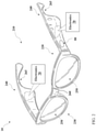
- FIG. 2 depicts an additional example audio device 10 , including audio eyeglasses 210 .
- the audio eyeglasses 210 can include a frame 220 having a lens region 230 and a pair of arms 240 extending from the lens region 230 .
- the lens region 230 and arms 240 are designed for resting on the head of a user.
- the lens region 230 can include a set of lenses 250 , which can include prescription, non-prescription and/or light-filtering lenses, as well as a bridge 260 (which may include padding) for resting on the user's nose.
- Arms 240 can include a contour 265 for resting on the user's respective ears.
- Electronics 70 can include portions of a capacitive sensing interface 80 , as described with respect to the audio devices 10 herein. In some cases, separate, or duplicate sets of electronics 70 are contained in portions of the frame, e.g., each of the respective arms 240 in the frame 220 . However, certain components described herein can also be present in singular form.
- FIG. 3 depicts another audio device 10 , including around-ear headphones 310 .
- Headphones 310 can include a pair of earcups 320 configured to fit over the ear, or on the ear, of a user.
- a headband 330 spans between the pair of earcups 320 and is configured to rest on the head of the user (e.g., spanning over the crown of the head or around the head).
- the headband 330 can include a head cushion 340 in some implementations.
- Electronics 70 can include portions of a capacitive sensing interface 80 , as described with respect to the wearable audio devices 10 herein. It is understood that a number of wearable audio devices described herein can utilize the features of the various implementations, and the wearable audio devices 10 shown and described with reference to FIGS. 1-3 are merely illustrative.
- FIG. 4 shows a schematic depiction of example electronics 70 contained (at least partially) within the audio devices 10 (e.g., as shown in FIGS. 1-3 ), along with components of the capacitive sensing interface 80 .
- one or more of the components in electronics 70 may be implemented as hardware and/or software, and that such components may be connected by any conventional means (e.g., hard-wired and/or wireless connection).
- any component described as connected or coupled to another component in the audio device 10 or other systems disclosed according to implementations may communicate using any conventional hard-wired connection and/or additional communications protocols.
- communications protocol(s) can include a Wi-Fi protocol using a wireless local area network (LAN), a communication protocol such as IEEE 802.11 b/g a cellular network-based protocol (e.g., third, fourth or fifth generation (3G, 4G, 5G cellular networks) or one of a plurality of internet-of-things (IoT) protocols, such as: Bluetooth, BLE Bluetooth, ZigBee (mesh LAN), Z-wave (sub-GHz mesh network), 6LoWPAN (a lightweight IP protocol), LTE protocols, RFID, ultrasonic audio protocols, etc.
- LAN wireless local area network
- a communication protocol such as IEEE 802.11 b/g a cellular network-based protocol (e.g., third, fourth or fifth generation (3G, 4G, 5G cellular networks) or one of a plurality of internet-of-things (IoT) protocols, such as: Bluetooth, BLE Bluetooth, ZigBee (mesh LAN), Z-wave (sub-GHz mesh network), 6Lo
- electronics 70 contained within the audio headset 20 can include a transducer 410 and a power source 420 .
- the electronics 70 can further include an inertial measurement unit (IMU) 430 for detecting movement of the wearable audio device 10 and enabling particular control functions.
- IMU inertial measurement unit
- the power source 420 is connected to the transducer 410 , and can additionally be connected to the IMU 430 .
- Each of the transducer 410 , power source 420 and IMU 90 are connected with a controller 440 , which is configured to perform control functions according to various implementations described herein.
- Electronics 70 can include other components not specifically depicted in the accompanying FIGURES, such as communications components (e.g., a wireless transceiver (WT)) configured to communicate with one or more other electronic devices connected via one or more wireless networks (e.g., a local WiFi network, Bluetooth connection, or radio frequency (RF) connection), and amplification and signal processing components. It is understood that these components or functional equivalents of these components can be connected with, or form part of, the controller 440 .
- communications components e.g., a wireless transceiver (WT)
- WT wireless transceiver
- RF radio frequency
- the transducer 410 can include at least one electroacoustic transducer for producing an acoustic output into, or proximate, the ears of a user.
- each transducer 410 can include a dipole loudspeaker with an acoustic driver or radiator that emits front-side acoustic radiation from its front side, and emits rear-side acoustic radiation to its rear side.
- the dipole loudspeaker can be built into the housing, frame or casing of the audio device 10 , and may be configured for the particular form factor of the audio device 10 .
- the IMU 430 can include a microelectromechanical system (MEMS) device that combines a multi-axis accelerometer, gyroscope, and/or magnetometer. It is understood that additional or alternative sensors may perform functions of the IMU 430 , e.g., an optical-based tracking system, accelerometer, magnetometer, gyroscope or radar for detecting movement as described herein.
- the IMU 430 can be configured to detect changes in the physical location/orientation of the audio device 10 , and provide updated sensor data to the controller 440 in order to indicate a change in the location/orientation of the audio device 10 .
- the electronics 70 can also include one or more optical or visual detection systems located at the audio device 10 or another connected device configured to detect the orientation of the audio device 10 .
- the power source 420 to the transducer 410 can be provided locally (e.g., with a battery proximate each transducer 410 ), or a single battery can transfer power via wiring (not shown) that passes through the frame or housing of the audio device 10 , e.g., depending upon the form factor of the particular wearable audio device 10 .
- the power source 420 can be used to control operation of the transducer 410 , according to various implementations.
- the controller 440 can include conventional hardware and/or software components for executing program instructions or code according to processes described herein.
- controller 440 may include one or more processors, memory, communications pathways between components, and/or one or more logic engines for executing program code.
- Controller 440 can be coupled with other components in the electronics 70 via any conventional wireless and/or hardwired connection which allows controller 440 to send/receive signals to/from those components and control operation thereof.
- Controller 440 is shown coupled with a printed circuit board (PCB) 450 , which in turn is coupled with the capacitive sensing interface 80 ( FIGS. 1-3 ).
- PCB printed circuit board
- the controller 440 is configured to receive touch-based commands from the capacitive sensing interface 80 in order to control operation of the audio device 10 .
- a user can provide a touch command at the capacitive sensing interface 80 in order to power the audio device 10 on or off, switch between playback sources, switch tracks or segments within a playback source, toggle through a menu of playback options, etc.
- FIGS. 5 and 6 show two distinct example cross-sectional depictions of a wall 500 through which the capacitive sensing interface 80 extends, e.g., an outer wall in the housing of any of the audio devices 10 shown and described herein.
- the wall 500 has an inner surface 510 and an outer surface 520 .
- the capacitive sensing interface 80 has a sensing surface 530 (e.g., contact surface) along the outer surface 520 of the wall 500 .
- the wall 500 includes a compound curved surface, such that the outer surface 520 of the wall 500 curves (or arcs) in both the X and Y directions.
- the inner surface 510 also has a compound curved shape. This example is illustrated in FIGS.
- the wall 500 has a substantially constant thickness (T w ) along the longest dimension of the interface 80 .
- the inner surface is faceted, such that the thickness of the wall (T w′ ) varies along its longest dimension. While a concave compound curve is illustrated in FIGS. 5 and 6 , it is understood that the inner surface 510 can have a convex compound curved shape in various implementations.
- the capacitive sensing interface 80 is integrated with the wall 500 , such that one or more commands (e.g., touch commands) can be received at the sensing surface 530 .
- commands e.g., touch commands
- a capacitive touch interface e.g., sensing surface 530 of capacitive sensing interface 80
- it forms a simple parallel plate capacitor, whose digital value is measured and used to detect presence at the particular electrode and/or movement across electrodes (such as in a swiping motion).
- the capacitive sensing interface 80 includes a plurality of electrodes 540 underlying the capacitive sensing surface 530 , e.g., to detect touch and/or swiping commands at the interface 80 .
- Electrodes 540 can include a sensor pad that is connected through the flexible PCB 450 to the controller 440 by one or more via and/or trace connections (not shown). Electrodes 540 can be surrounded or otherwise isolated by a ground hatch 550 .
- the flexible PCB 450 extends along the inner surface 510 of the wall 500 .
- the flexible PCB 450 can be coupled with the inner surface 510 using an adhesive, e.g., a conventional adhesive used in electronics manufacturing.
- the configuration of the flexible PCB 450 enables that PCB 450 to be effectively adhered to the inner surface 510 without the need for high-strength (e.g., very high bond, or VHB) adhesives.
- the flexible PCB 450 includes at least one slit 560 that enables the flexible PCB 450 to conform with the compound curve of the inner surface 510 .
- FIG. 7 shows a plan view of the flexible PCB 450 , which further illustrates sections 570 at least partially separated by the slit(s) 560 (with separate slits denoted by: a, b, c, d, etc.).
- slits 560 extend from one or more edge(s) 580 of the PCB 450 , e.g., as an opening on one of the edges 580 .
- FIG. 7 shows a plan view of the flexible PCB 450 , which further illustrates sections 570 at least partially separated by the slit(s) 560 (with separate slits denoted by: a, b, c, d, etc.).
- slits 560 extend from one or more edge(s) 580 of the PCB 450 , e.g., as an opening on
- the flexible PCB 450 has two slits 560 on each edge 580 that partially separate three sections 570 .
- any number of slits 560 greater than one can be used to separate corresponding sections 570 in the PCB 450 .
- slits 560 are evenly spaced across one or more of the edges 580 , such that any two slits 560 in a group of three or more slits 560 are separated by an equal space as measured along an edge 580 .
- slits 560 are equally spaced from corners 590 between edges 580 .
- slits 560 are equally spaced from corners 590 and from one another, such that a spacing between adjacent slits 560 is equal to a spacing between a slit 560 and a nearest corner 590 . In still other cases, the slits 560 are closer together than each slit 560 is spaced from a corner 590 , such that spacing between the slits 560 is not equal to a spacing with a nearest corner 590 .
- each slit 560 has a length-to-width ratio (length measured from edge 580 inward, and width measured parallel to inner surface 510 ) of at least 1:1. In certain additional implementations, each slit 560 has a length-to-width ratio of at least 2:1 or at least 3:1. In certain implementations, the length-to-width ratio of each slit 560 is proportional to the thickness of the PCB 450 , such that a thicker PCB 450 allows for a greater length-to-width ratio for each slit 560 .
- slits 560 extend only partially through the flexible PCB 450 in the X and Y direction. That is, each slit 560 extends along only part of the length or width of the flexible PCB 450 . In certain cases, for example as illustrated in FIG. 7 , each slit 560 extends entirely through the PCB 450 in the Z direction (or, depth direction, indicated as into and out of the page). However, in other implementations, each slit 560 extends only partially through the PCB 450 in the Z direction. Once coupled with the inner surface 510 of the wall 500 , the PCB 450 is configured to flex at the slit(s) 560 in order to conform with that inner surface 510 .
- the slit(s) 560 enable the PCB 450 to conform with the compound curve of the inner surface 510 without interference between adjacent sections 570 . That is, in contrast to conventional configurations, the PCB 450 is configured to flex and conform to the compound curve of the inner surface 510 without causing mechanical stress on that PCB 450 and its circuitry. Additionally, because the slits 560 mitigate tension in the PCB 450 , that PCB 450 is more effectively coupled (e.g., adhered) to the inner surface 510 when compared with conventional approaches.
- a wall 500 A of an audio device 10 is shown with an inner surface 510 A that includes facets 600 connected by a set of junctions 610 .
- at least one junction 610 separates at least two facets 600 .
- the wall 500 A includes at least three facets 600 that are separated by at least two junctions 610 .
- the facets 600 are planar or approximately (e.g., within a margin of measurement error such as by several percent or less) planar, and are positioned at angles relative to one another due to the junctions 610 .
- each of the facets 600 has an approximately equal surface area. However, in other implementations, one or more facets 600 has a distinct surface area from a remainder of the facets 600 .
- the junctions 610 permit the inner surface 510 A to approximate a contour, e.g., in order to approximately track the compound curved shape of the outer surface 520 .
- the junctions 610 can include slots or tracks that extend entirely through the wall 500 A in the lengthwise or widthwise directions. In other cases, the junctions 610 are simply the interface between adjacent facets 600 , with minimal or negligible width or depth relative the surface of the facets 600 .
- the inner surface 510 A can include a grid or matrix of junctions 610 that enable the wall 500 A to approximate a compound curve (e.g., to approximate a curve in two different directions).
- each facet 600 has a non-uniform thickness across its length, such that a portion of each facet 600 is thinner proximate a junction 610 with an adjacent facet than a remaining portion of the facet 600 . That is, in addition to junctions 610 , the wall 500 A can include tapered facets 600 that thin as they approach junctions 610 , which can further enable the wall 500 A to approximate a compound curve.
- the flexible PCB 450 is coupled with (e.g., adhered to) the inner surface 510 A, e.g., at the facets 600 .
- the flexible PCB 450 including slits 560 is configured to mate with the inner surface 510 A, e.g., where sections 570 of the PCB 450 correspond with facets 600 of the inner surface 510 A.
- one or more of the junctions 610 can align with slits 560 in the PCB 450 , further enhancing the bond between the PCB 450 and the inner surface 510 A of the wall 500 A.
- the wall 500 A enables improved coupling with either PCB 450 or PCB(s) 650 , such that mechanical stresses from that coupling are mitigated when compared with conventional configurations.
- the faceted wall 500 A also enables coupling with distinct PCBs and/or other circuitry while mitigating mechanical stresses on bonding between those circuit components and the interface 80 .
- FIG. 11 shows an additional implementation of a wall 500 B, viewed from the inner surface 510 B, according to various additional implementations.
- the inner surface 510 B has at least one section with a simple curved shape, i.e., section(s) that only curve in one of the X or Y directions.
- the inner surface 510 B includes a set of facets 600 , and adjacent to the facets 600 , are simple curved sections 620 .
- Simple curved sections 620 are understood to curve outward (concave) along the X axis in this example.
- facets 600 can extend lengthwise in the X direction and adjacent curved sections 620 can curve (e.g., outward) along the Y axis.
- junctions 610 can be aligned with slits 560 in a PCB (e.g., in PCB 450 , FIG. 7 ).
- junctions 610 are misaligned with one or more slits 560 in a PCB (e.g., PCB 450 , FIG. 7 ) that is mounted to the inner surface 510 B.
- the functionality described herein, or portions thereof, and its various modifications can be implemented, at least in part, via a computer program product, e.g., a computer program tangibly embodied in an information carrier, such as one or more non-transitory machine-readable media, for execution by, or to control the operation of, one or more data processing apparatus, e.g., a programmable processor, a computer, multiple computers, and/or programmable logic components.
- a computer program product e.g., a computer program tangibly embodied in an information carrier, such as one or more non-transitory machine-readable media, for execution by, or to control the operation of, one or more data processing apparatus, e.g., a programmable processor, a computer, multiple computers, and/or programmable logic components.
- a computer program can be written in any form of programming language, including compiled or interpreted languages, and it can be deployed in any form, including as a stand-alone program or as a module, component, subroutine, or other unit suitable for use in a computing environment.
- a computer program can be deployed to be executed on one computer or on multiple computers at one site or distributed across multiple sites and interconnected by a network.
- Actions associated with implementing all or part of the functions can be performed by one or more programmable processors executing one or more computer programs to perform the functions of the calibration process. All or part of the functions can be implemented as, special purpose logic circuitry, e.g., an FPGA and/or an ASIC (application-specific integrated circuit).
- processors suitable for the execution of a computer program include, by way of example, both general and special purpose microprocessors, and any one or more processors of any kind of digital computer.
- a processor will receive instructions and data from a read-only memory or a random access memory or both.
- Components of a computer include a processor for executing instructions and one or more memory devices for storing instructions and data.
- Elements of figures are shown and described as discrete elements in a block diagram. These may be implemented as one or more of analog circuitry or digital circuitry. Alternatively, or additionally, they may be implemented with one or more microprocessors executing software instructions.
- the software instructions can include digital signal processing instructions. Operations may be performed by analog circuitry or by a microprocessor executing software that performs the equivalent of the analog operation.
- Signal lines may be implemented as discrete analog or digital signal lines, as a discrete digital signal line with appropriate signal processing that is able to process separate signals, and/or as elements of a wireless communication system.
- the steps may be performed by one element or a plurality of elements. The steps may be performed together or at different times.
- the elements that perform the activities may be physically the same or proximate one another, or may be physically separate.
- One element may perform the actions of more than one block.
- Audio signals may be encoded or not, and may be transmitted in either digital or analog form. Conventional audio signal processing equipment and operations are in some cases omitted from the drawings.
- components described as being “coupled” to one another can be joined along one or more interfaces.
- these interfaces can include junctions between distinct components, and in other cases, these interfaces can include a solidly and/or integrally formed interconnection. That is, in some cases, components that are “coupled” to one another can be simultaneously formed to define a single continuous member.
- these coupled components can be formed as separate members and be subsequently joined through known processes (e.g., soldering, fastening, ultrasonic welding, bonding).
- electronic components described as being “coupled” can be linked via conventional hard-wired and/or wireless means such that these electronic components can communicate data with one another. Additionally, sub-components within a given component can be considered to be linked via conventional pathways, which may not necessarily be illustrated.
Abstract
Various aspects include audio devices with a capacitive sensing interface along a compound curved wall. Some aspects of the disclosure relate to wearable audio devices with a capacitive sensing interface and a flexible printed circuit board (PCB) for detecting a touch command at the interface. In certain cases, the flexible PCB has at least one slit for conforming to the compound curve of the wall. In additional implementations, the inner surface of the wall is faceted and the flexible PCB conforms to the facets in the wall.
Description
This disclosure generally relates to audio devices. More particularly, the disclosure relates to a capacitive sensing interface with a compound curved shaped in audio devices.
Audio devices, for example wearable audio devices such as earbuds, can include compound curved surfaces. In particular form factors, it is beneficial to integrate capacitive sensing interfaces along these compound curved surfaces. However, conventional capacitive sensing interfaces employ circuitry including a planar, flexible printed circuit board (PCB). Fastening the planar, flexible PCB to a compound curved surface can create stresses in the flexible PCB, impacting performance and potentially causing the interface to fail.
All examples and features mentioned below can be combined in any technically possible way.
Various implementations of the disclosure include audio devices with a capacitive sensing interface. Various particular implementations of the disclosure include an audio device with a capacitive sensing interface integrated into a wall with a compound curved shape.
In some particular aspects, an audio device includes: a housing having a set of walls, where at least one of the walls has a compound curved shape including an outer surface and an inner surface each with a compound curve; and a capacitive sensing interface integrated with the wall having the compound curved shape, the capacitive sensing interface including: a contact surface for receiving a touch command at the outer surface of the wall; and a flexible printed circuit board (PCB) underlying the contact surface for detecting the touch command at the contact surface, where the flexible PCB extends along the inner surface of the wall and includes at least one slit that enable the flexible PCB to conform with the compound curve of the inner surface.
In other particular aspects, an audio device includes: a housing having a set of walls, where at least one of the walls has a compound curved shape including an outer surface and an inner surface, where the inner surface includes distinct facets connected by a set of junctions; and a capacitive sensing interface integrated with the wall having the compound curved shape, the capacitive sensing interface including: a contact surface for receiving a touch command at the outer surface of the wall; and a flexible printed circuit board (PCB) underlying the contact surface for detecting the touch command at the contact surface, where the flexible PCB extends along the inner surface of the wall.
Implementations may include one of the following features, or any combination thereof.
In certain aspects, each slit partially separates sections of the flexible PCB.
In some cases, the at least one slit includes at least two slits that partially separate at least three sections of the flexible PCB.
In particular implementations, the at least one slit enables the flexible PCB to conform with the compound curve of the inner surface without interference between adjacent sections of the flexible PCB.
In certain cases, each slit has a length-to-width ratio of at least 1:1.
In some implementations, the audio device further includes: an acoustic transducer having a sound-radiating surface for providing an audio output; and a controller coupled with the acoustic transducer and the flexible PCB, the controller configured to control the audio output from the acoustic transducer based on commands received at the capacitive sensing interface.
In particular aspects, the capacitive sensing interface includes a capacitive touch interface for detecting the touch command from a human user.
In certain implementations, the compound curve of the inner surface includes a convex compound curve or a concave compound curve.
In some cases, the audio device includes a wearable audio device including at least one of: headphones, earphones, audio eyeglasses, body-worn speakers, or audio jewelry.
In particular aspects, the wall has a substantially constant thickness along a longest dimension of the capacitive sensing interface.
In certain implementations, the audio device further includes an adhesive coupling the flexible PCB with the inner surface of the wall.
In some aspects, the set of junctions includes at least two junctions that connect at least three facets of the inner surface.
In certain cases, each facet has a non-uniform thickness across its length such that a portion of each facet is thinner proximate a junction with an adjacent facet than a remaining portion of the facet.
In particular implementations, the set of junctions enable the flexible PCB to conform with the inner surface without interference between adjacent sections of the flexible PCB.
In some cases, the audio device further includes an adhesive coupling the flexible PCB with the inner surface of the wall, where each of the facets has an approximately equal surface area.
In certain aspects, the audio device further includes an acoustic transducer having a sound-radiating surface for providing an audio output; and a controller coupled with the acoustic transducer and the flexible PCB, the controller configured to control the audio output from the acoustic transducer based on commands received at the capacitive sensing interface, where the capacitive sensing interface includes a capacitive touch interface for detecting the touch command from a human user.
In particular implementations, the compound curve of the outer surface includes a concave compound curve.
In some cases, the inner surface further includes at least one curved section adjacent to at least one of the facets.
In certain aspects, the flexible PCB has at least one slit that enable the flexible PCB to conform with the faceted inner surface.
Two or more features described in this disclosure, including those described in this summary section, may be combined to form implementations not specifically described herein.
The details of one or more implementations are set forth in the accompanying drawings and the description below. Other features, objects and advantages will be apparent from the description and drawings, and from the claims.
It is noted that the drawings of the various implementations are not necessarily to scale. The drawings are intended to depict only typical aspects of the disclosure, and therefore should not be considered as limiting the scope of the invention. In the drawings, like numbering represents like elements between the drawings.
As noted herein, various aspects of the disclosure generally relate to audio devices with a capacitive sensing interface along a compound curved wall. More particularly, aspects of the disclosure relate to wearable audio devices with a capacitive sensing interface and a flexible printed circuit board (PCB) for detecting a touch command at the interface. In certain cases, the flexible PCB has at least one slit for conforming to the compound curve of the wall. In additional implementations, the inner surface of the wall is faceted and the flexible PCB conforms to the facets in the wall.
Commonly labeled components in the FIGURES are considered to be substantially equivalent components for the purposes of illustration, and redundant discussion of those components is omitted for clarity.
Aspects and implementations disclosed herein may be applicable to a wide variety of speaker systems, such as audio devices and wearable audio devices. Audio devices can include fixed and/or portable speakers, speakers integrated into other systems (e.g., automobile audio systems), and/or networks of speakers. In some cases, wearable audio devices can take various form factors, such as headphones (whether on or off ear), headsets, watches, eyeglasses, audio accessories or clothing (e.g., audio hats, audio visors, audio jewelry), neck-worn speakers, shoulder-worn speakers, body-worn speakers, etc. Some particular aspects disclosed may be particularly applicable to personal (wearable) audio devices such as in-ear headphones (also referred to as earbuds), eyeglasses or other head-mounted audio devices. It should be noted that although specific implementations of speaker systems primarily serving the purpose of acoustically outputting audio are presented with some degree of detail, such presentations of specific implementations are intended to facilitate understanding through provision of examples and should not be taken as limiting either the scope of disclosure or the scope of claim coverage.
The wearable audio devices described according to various implementations can include features found in one or more other wearable electronic devices, such as smart glasses, smart watches, etc. These wearable audio devices can include additional hardware components, such as one or more cameras, location tracking devices, microphones, etc., and may be capable of voice recognition, visual recognition, and other smart device functions. The description of wearable audio devices included herein is not intended to exclude these additional capabilities in such a device.
As noted herein, conventional capacitive sensing interfaces employ circuitry including a planar, flexible printed circuit board (PCB). Fastening the planar, flexible PCB to a compound curved surface (i.e., a surface with curves in both X and Y directions) can create stresses in the flexible PCB, as well as cause the flexible PCB to detach from the device wall. These issues can lead to decreased sensitivity at the interface, and in some cases, interface failure.
In contrast to conventional devices, various implementations include audio devices with a flexible PCB that has at least one slit to enable the PCB to conform with the compound curve of the inner surface of the device wall. In additional implementations, the inner surface of the device wall is faceted to enable the PCB to conform with that surface. In certain cases, the inner surface is faceted and the PCB includes at least one slit to enable that PCB to conform with the faceted surface of the device wall.
As shown in FIG. 4 , electronics 70 contained within the audio headset 20 (FIG. 1 ) can include a transducer 410 and a power source 420. In certain implementations (depicted in phantom as optional), the electronics 70 can further include an inertial measurement unit (IMU) 430 for detecting movement of the wearable audio device 10 and enabling particular control functions. In various implementations, the power source 420 is connected to the transducer 410, and can additionally be connected to the IMU 430. Each of the transducer 410, power source 420 and IMU 90 are connected with a controller 440, which is configured to perform control functions according to various implementations described herein. Electronics 70 can include other components not specifically depicted in the accompanying FIGURES, such as communications components (e.g., a wireless transceiver (WT)) configured to communicate with one or more other electronic devices connected via one or more wireless networks (e.g., a local WiFi network, Bluetooth connection, or radio frequency (RF) connection), and amplification and signal processing components. It is understood that these components or functional equivalents of these components can be connected with, or form part of, the controller 440.
The transducer 410 can include at least one electroacoustic transducer for producing an acoustic output into, or proximate, the ears of a user. In certain implementations (e.g., in the audio eyeglasses example of FIG. 2 ), each transducer 410 can include a dipole loudspeaker with an acoustic driver or radiator that emits front-side acoustic radiation from its front side, and emits rear-side acoustic radiation to its rear side. The dipole loudspeaker can be built into the housing, frame or casing of the audio device 10, and may be configured for the particular form factor of the audio device 10.
The IMU 430 can include a microelectromechanical system (MEMS) device that combines a multi-axis accelerometer, gyroscope, and/or magnetometer. It is understood that additional or alternative sensors may perform functions of the IMU 430, e.g., an optical-based tracking system, accelerometer, magnetometer, gyroscope or radar for detecting movement as described herein. The IMU 430 can be configured to detect changes in the physical location/orientation of the audio device 10, and provide updated sensor data to the controller 440 in order to indicate a change in the location/orientation of the audio device 10. However, it is understood that the electronics 70 can also include one or more optical or visual detection systems located at the audio device 10 or another connected device configured to detect the orientation of the audio device 10.
The power source 420 to the transducer 410 can be provided locally (e.g., with a battery proximate each transducer 410), or a single battery can transfer power via wiring (not shown) that passes through the frame or housing of the audio device 10, e.g., depending upon the form factor of the particular wearable audio device 10. The power source 420 can be used to control operation of the transducer 410, according to various implementations.
The controller 440 can include conventional hardware and/or software components for executing program instructions or code according to processes described herein. For example, controller 440 may include one or more processors, memory, communications pathways between components, and/or one or more logic engines for executing program code. Controller 440 can be coupled with other components in the electronics 70 via any conventional wireless and/or hardwired connection which allows controller 440 to send/receive signals to/from those components and control operation thereof.
With continuing reference to FIGS. 5 and 6 , the capacitive sensing interface 80 is integrated with the wall 500, such that one or more commands (e.g., touch commands) can be received at the sensing surface 530. As is known in the art, when a user (e.g., a user's finger) touches the contact surface of a capacitive touch interface (e.g., sensing surface 530 of capacitive sensing interface 80), it forms a simple parallel plate capacitor, whose digital value is measured and used to detect presence at the particular electrode and/or movement across electrodes (such as in a swiping motion). In various implementations, the capacitive sensing interface 80 includes a plurality of electrodes 540 underlying the capacitive sensing surface 530, e.g., to detect touch and/or swiping commands at the interface 80. Electrodes 540 can include a sensor pad that is connected through the flexible PCB 450 to the controller 440 by one or more via and/or trace connections (not shown). Electrodes 540 can be surrounded or otherwise isolated by a ground hatch 550.
As noted herein, in various implementations, the flexible PCB 450 extends along the inner surface 510 of the wall 500. In these cases, the flexible PCB 450 can be coupled with the inner surface 510 using an adhesive, e.g., a conventional adhesive used in electronics manufacturing. In certain implementations, the configuration of the flexible PCB 450 enables that PCB 450 to be effectively adhered to the inner surface 510 without the need for high-strength (e.g., very high bond, or VHB) adhesives.
As shown in FIGS. 5 and 6 , the flexible PCB 450 includes at least one slit 560 that enables the flexible PCB 450 to conform with the compound curve of the inner surface 510. FIG. 7 shows a plan view of the flexible PCB 450, which further illustrates sections 570 at least partially separated by the slit(s) 560 (with separate slits denoted by: a, b, c, d, etc.). In some cases, slits 560 extend from one or more edge(s) 580 of the PCB 450, e.g., as an opening on one of the edges 580. In the example depicted in FIG. 7 , the flexible PCB 450 has two slits 560 on each edge 580 that partially separate three sections 570. However, it is understood that any number of slits 560 greater than one can be used to separate corresponding sections 570 in the PCB 450. In some cases, slits 560 are evenly spaced across one or more of the edges 580, such that any two slits 560 in a group of three or more slits 560 are separated by an equal space as measured along an edge 580. In some cases, slits 560 are equally spaced from corners 590 between edges 580. In further implementations, slits 560 are equally spaced from corners 590 and from one another, such that a spacing between adjacent slits 560 is equal to a spacing between a slit 560 and a nearest corner 590. In still other cases, the slits 560 are closer together than each slit 560 is spaced from a corner 590, such that spacing between the slits 560 is not equal to a spacing with a nearest corner 590.
In some cases, each slit 560 has a length-to-width ratio (length measured from edge 580 inward, and width measured parallel to inner surface 510) of at least 1:1. In certain additional implementations, each slit 560 has a length-to-width ratio of at least 2:1 or at least 3:1. In certain implementations, the length-to-width ratio of each slit 560 is proportional to the thickness of the PCB 450, such that a thicker PCB 450 allows for a greater length-to-width ratio for each slit 560.
In various implementations, slits 560 extend only partially through the flexible PCB 450 in the X and Y direction. That is, each slit 560 extends along only part of the length or width of the flexible PCB 450. In certain cases, for example as illustrated in FIG. 7 , each slit 560 extends entirely through the PCB 450 in the Z direction (or, depth direction, indicated as into and out of the page). However, in other implementations, each slit 560 extends only partially through the PCB 450 in the Z direction. Once coupled with the inner surface 510 of the wall 500, the PCB 450 is configured to flex at the slit(s) 560 in order to conform with that inner surface 510. In particular cases, the slit(s) 560 enable the PCB 450 to conform with the compound curve of the inner surface 510 without interference between adjacent sections 570. That is, in contrast to conventional configurations, the PCB 450 is configured to flex and conform to the compound curve of the inner surface 510 without causing mechanical stress on that PCB 450 and its circuitry. Additionally, because the slits 560 mitigate tension in the PCB 450, that PCB 450 is more effectively coupled (e.g., adhered) to the inner surface 510 when compared with conventional approaches.
In additional implementations, for example as shown in FIGS. 8 and 9 , a wall 500A of an audio device 10 is shown with an inner surface 510A that includes facets 600 connected by a set of junctions 610. In certain implementations, at least one junction 610 separates at least two facets 600. In particular examples, the wall 500A includes at least three facets 600 that are separated by at least two junctions 610. In these cases, the facets 600 are planar or approximately (e.g., within a margin of measurement error such as by several percent or less) planar, and are positioned at angles relative to one another due to the junctions 610. In some example implementations, each of the facets 600 has an approximately equal surface area. However, in other implementations, one or more facets 600 has a distinct surface area from a remainder of the facets 600.
According to various implementations, the junctions 610 permit the inner surface 510A to approximate a contour, e.g., in order to approximately track the compound curved shape of the outer surface 520. The junctions 610 can include slots or tracks that extend entirely through the wall 500A in the lengthwise or widthwise directions. In other cases, the junctions 610 are simply the interface between adjacent facets 600, with minimal or negligible width or depth relative the surface of the facets 600. In certain cases, as illustrated in the plan view of wall 500A in FIG. 10 , the inner surface 510A can include a grid or matrix of junctions 610 that enable the wall 500A to approximate a compound curve (e.g., to approximate a curve in two different directions). In additional implementations, each facet 600 has a non-uniform thickness across its length, such that a portion of each facet 600 is thinner proximate a junction 610 with an adjacent facet than a remaining portion of the facet 600. That is, in addition to junctions 610, the wall 500A can include tapered facets 600 that thin as they approach junctions 610, which can further enable the wall 500A to approximate a compound curve.
In certain implementations, as shown in FIGS. 9 and 10 , the flexible PCB 450 is coupled with (e.g., adhered to) the inner surface 510A, e.g., at the facets 600. According to particular implementations, the flexible PCB 450 including slits 560 is configured to mate with the inner surface 510A, e.g., where sections 570 of the PCB 450 correspond with facets 600 of the inner surface 510A. In these cases, one or more of the junctions 610 can align with slits 560 in the PCB 450, further enhancing the bond between the PCB 450 and the inner surface 510A of the wall 500A.
In any case, the wall 500A enables improved coupling with either PCB 450 or PCB(s) 650, such that mechanical stresses from that coupling are mitigated when compared with conventional configurations. The faceted wall 500A also enables coupling with distinct PCBs and/or other circuitry while mitigating mechanical stresses on bonding between those circuit components and the interface 80.
The functionality described herein, or portions thereof, and its various modifications (hereinafter “the functions”) can be implemented, at least in part, via a computer program product, e.g., a computer program tangibly embodied in an information carrier, such as one or more non-transitory machine-readable media, for execution by, or to control the operation of, one or more data processing apparatus, e.g., a programmable processor, a computer, multiple computers, and/or programmable logic components.
A computer program can be written in any form of programming language, including compiled or interpreted languages, and it can be deployed in any form, including as a stand-alone program or as a module, component, subroutine, or other unit suitable for use in a computing environment. A computer program can be deployed to be executed on one computer or on multiple computers at one site or distributed across multiple sites and interconnected by a network.
Actions associated with implementing all or part of the functions can be performed by one or more programmable processors executing one or more computer programs to perform the functions of the calibration process. All or part of the functions can be implemented as, special purpose logic circuitry, e.g., an FPGA and/or an ASIC (application-specific integrated circuit). Processors suitable for the execution of a computer program include, by way of example, both general and special purpose microprocessors, and any one or more processors of any kind of digital computer. Generally, a processor will receive instructions and data from a read-only memory or a random access memory or both. Components of a computer include a processor for executing instructions and one or more memory devices for storing instructions and data.
Elements of figures are shown and described as discrete elements in a block diagram. These may be implemented as one or more of analog circuitry or digital circuitry. Alternatively, or additionally, they may be implemented with one or more microprocessors executing software instructions. The software instructions can include digital signal processing instructions. Operations may be performed by analog circuitry or by a microprocessor executing software that performs the equivalent of the analog operation. Signal lines may be implemented as discrete analog or digital signal lines, as a discrete digital signal line with appropriate signal processing that is able to process separate signals, and/or as elements of a wireless communication system.
When processes are represented or implied in the block diagram, the steps may be performed by one element or a plurality of elements. The steps may be performed together or at different times. The elements that perform the activities may be physically the same or proximate one another, or may be physically separate. One element may perform the actions of more than one block. Audio signals may be encoded or not, and may be transmitted in either digital or analog form. Conventional audio signal processing equipment and operations are in some cases omitted from the drawings.
In various implementations, components described as being “coupled” to one another can be joined along one or more interfaces. In some implementations, these interfaces can include junctions between distinct components, and in other cases, these interfaces can include a solidly and/or integrally formed interconnection. That is, in some cases, components that are “coupled” to one another can be simultaneously formed to define a single continuous member. However, in other implementations, these coupled components can be formed as separate members and be subsequently joined through known processes (e.g., soldering, fastening, ultrasonic welding, bonding). In various implementations, electronic components described as being “coupled” can be linked via conventional hard-wired and/or wireless means such that these electronic components can communicate data with one another. Additionally, sub-components within a given component can be considered to be linked via conventional pathways, which may not necessarily be illustrated.
Other embodiments not specifically described herein are also within the scope of the following claims. Elements of different implementations described herein may be combined to form other embodiments not specifically set forth above. Elements may be left out of the structures described herein without adversely affecting their operation. Furthermore, various separate elements may be combined into one or more individual elements to perform the functions described herein.
Claims (20)
1. An audio device comprising:
a housing comprising a set of walls, wherein at least one of the walls has a compound curved shape comprising an outer surface and an inner surface each with a compound curve; and
a capacitive sensing interface integrated with the wall having the compound curved shape, the capacitive sensing interface comprising:
a contact surface for receiving a touch command at the outer surface of the wall; and
a flexible printed circuit board (PCB) underlying the contact surface for detecting the touch command at the contact surface, wherein the flexible PCB extends along the inner surface of the wall and comprises at least one slit that enable the flexible PCB to conform with the compound curve of the inner surface.
2. The audio device of claim 1 , wherein each of the at least one slit partially separates sections of the flexible PCB.
3. The audio device of claim 2 , wherein the at least one slit comprises at least two slits that partially separate at least three sections of the flexible PCB.
4. The audio device of claim 2 , wherein the at least one slit enables the flexible PCB to conform with the compound curve of the inner surface without interference between adjacent sections of the flexible PCB.
5. The audio device of claim 1 , wherein each slit has a length-to-width ratio of at least 1:1.
6. The audio device of claim 1 , further comprising:
an acoustic transducer comprising a sound-radiating surface for providing an audio output; and
a controller coupled with the acoustic transducer and the flexible PCB, the controller configured to control the audio output from the acoustic transducer based on commands received at the capacitive sensing interface.
7. The audio device of claim 1 , wherein the capacitive sensing interface comprises a capacitive touch interface for detecting the touch command from a human user.
8. The audio device of claim 1 , wherein the compound curve of the inner surface comprises a convex compound curve or a concave compound curve.
9. The audio device of claim 1 , wherein the audio device comprises a wearable audio device comprising at least one of: headphones, earphones, audio eyeglasses, body-worn speakers, or audio jewelry.
10. The audio device of claim 1 , wherein the wall has a substantially constant thickness along a longest dimension of the capacitive sensing interface.
11. The audio device of claim 1 , further comprising an adhesive coupling the flexible PCB with the inner surface of the wall.
12. An audio device comprising:
a housing comprising a set of walls, wherein at least one of the walls has a compound curved shape comprising an outer surface and an inner surface, wherein the inner surface comprises distinct facets connected by a set of junctions; and
a capacitive sensing interface integrated with the wall having the compound curved shape, the capacitive sensing interface comprising:
a contact surface for receiving a touch command at the outer surface of the wall; and
a flexible printed circuit board (PCB) underlying the contact surface for detecting the touch command at the contact surface, wherein the flexible PCB extends along the inner surface of the wall.
13. The audio device of claim 12 , wherein the set of junctions comprises at least two junctions that connect at least three facets of the inner surface.
14. The audio device of claim 12 , wherein each facet has a non-uniform thickness across its length such that a portion of each facet is thinner proximate a junction with an adjacent facet than a remaining portion of the facet.
15. The audio device of claim 12 , wherein the set of junctions enable the flexible PCB to conform with the inner surface without interference between adjacent sections of the flexible PCB.
16. The audio device of claim 12 , further comprising an adhesive coupling the flexible PCB with the inner surface of the wall, wherein each of the facets has an approximately equal surface area.
17. The audio device of claim 12 , further comprising:
an acoustic transducer comprising a sound-radiating surface for providing an audio output; and
a controller coupled with the acoustic transducer and the flexible PCB, the controller configured to control the audio output from the acoustic transducer based on commands received at the capacitive sensing interface,
wherein the capacitive sensing interface comprises a capacitive touch interface for detecting the touch command from a human user.
18. The audio device of claim 12 , wherein the compound curve of the outer surface comprises a concave compound curve, and wherein the inner surface further comprises at least one curved section adjacent to at least one of the facets.
19. The audio device of claim 12 , wherein the audio device comprises a wearable audio device comprising at least one of: headphones, earphones, audio eyeglasses, body-worn speakers, or audio jewelry.
20. The audio device of claim 12 , wherein the flexible PCB comprises at least one slit that enable the flexible PCB to conform with the inner surface.
Priority Applications (4)
| Application Number | Priority Date | Filing Date | Title |
|---|---|---|---|
| US16/919,634 US11275471B2 (en) | 2020-07-02 | 2020-07-02 | Audio device with flexible circuit for capacitive interface |
| EP21745664.9A EP4176588B1 (en) | 2020-07-02 | 2021-07-01 | Audio device with flexible circuit for capacitive interface |
| CN202180060778.XA CN116157767A (en) | 2020-07-02 | 2021-07-01 | Audio device with flexible circuit for capacitive interface |
| PCT/US2021/040096 WO2022006401A1 (en) | 2020-07-02 | 2021-07-01 | Audio device with flexible circuit for capacitive interface |
Applications Claiming Priority (1)
| Application Number | Priority Date | Filing Date | Title |
|---|---|---|---|
| US16/919,634 US11275471B2 (en) | 2020-07-02 | 2020-07-02 | Audio device with flexible circuit for capacitive interface |
Publications (2)
| Publication Number | Publication Date |
|---|---|
| US20220004272A1 US20220004272A1 (en) | 2022-01-06 |
| US11275471B2 true US11275471B2 (en) | 2022-03-15 |
Family
ID=77022361
Family Applications (1)
| Application Number | Title | Priority Date | Filing Date |
|---|---|---|---|
| US16/919,634 Active 2040-11-05 US11275471B2 (en) | 2020-07-02 | 2020-07-02 | Audio device with flexible circuit for capacitive interface |
Country Status (4)
| Country | Link |
|---|---|
| US (1) | US11275471B2 (en) |
| EP (1) | EP4176588B1 (en) |
| CN (1) | CN116157767A (en) |
| WO (1) | WO2022006401A1 (en) |
Families Citing this family (3)
| Publication number | Priority date | Publication date | Assignee | Title |
|---|---|---|---|---|
| US20220382508A1 (en) * | 2021-06-01 | 2022-12-01 | Sonos Inc. | Playback Device with Conforming Capacitive Touch Sensor Assembly |
| USD971890S1 (en) * | 2021-06-24 | 2022-12-06 | Shenzhen Xinzhengyu Technology Co., Ltd | Earphones |
| USD1003870S1 (en) * | 2022-03-16 | 2023-11-07 | Shanxi Jonter Intelligent Technology Co., Ltd | Set of earphones and charging case |
Citations (71)
| Publication number | Priority date | Publication date | Assignee | Title |
|---|---|---|---|---|
| US6452494B1 (en) | 1999-09-27 | 2002-09-17 | Intel Corporation | Activating devices |
| US20050277446A1 (en) | 2004-06-09 | 2005-12-15 | Partner Tech. Corporation | Wireless earphone enabling a ringing signal and method for controlling the ringing signal |
| US20060013079A1 (en) | 2004-07-06 | 2006-01-19 | Sony Corporation | Playback system, headphones, playback apparatus and method, and recording medium and program for controlling playback apparatus and method |
| US20060045304A1 (en) | 2004-09-02 | 2006-03-02 | Maxtor Corporation | Smart earphone systems devices and methods |
| US7010332B1 (en) | 2000-02-21 | 2006-03-07 | Telefonaktiebolaget Lm Ericsson(Publ) | Wireless headset with automatic power control |
| US20060233413A1 (en) | 2005-03-25 | 2006-10-19 | Seong-Hyun Nam | Automatic control earphone system using capacitance sensor |
| US20070274530A1 (en) | 2004-04-05 | 2007-11-29 | Koninklijke Philips Electronics, N.V. | Audio Entertainment System, Device, Method, And Computer Program |
| US20070281762A1 (en) | 2006-05-31 | 2007-12-06 | Motorola, Inc. | Signal routing to a communication accessory based on device activation |
| US20070297618A1 (en) | 2006-06-26 | 2007-12-27 | Nokia Corporation | System and method for controlling headphones |
| US20080130910A1 (en) | 2006-11-30 | 2008-06-05 | Motorola, Inc. | Gestural user interface devices and methods for an accessory to a wireless communication device |
| US20080130936A1 (en) | 2006-10-02 | 2008-06-05 | Plantronics, Inc. | Online audio availability detection |
| US20080143681A1 (en) | 2006-12-18 | 2008-06-19 | Xiaoping Jiang | Circular slider with center button |
| US20080260176A1 (en) | 2005-10-28 | 2008-10-23 | Koninklijke Philips Electronics, N.V. | System and Method For Controlling a Device Using Position and Touch |
| EP2009949A1 (en) | 2007-06-25 | 2008-12-31 | Modelabs Technologies Limited | Wireless telephony device, such as a telephone or an earphone, equipped with a speaker and an element for automatic volume adjustment |
| US20090009491A1 (en) | 2007-07-04 | 2009-01-08 | Grivna Edward L | Capacitive sensing control knob |
| US20090124286A1 (en) | 2007-11-12 | 2009-05-14 | Sony Ericsson Mobile Communications Ab | Portable hands-free device with sensor |
| US20090131124A1 (en) | 2007-11-20 | 2009-05-21 | Broadcom Corporation | Wireless earpiece determining proximity to user and operation based thereon |
| US20090154720A1 (en) | 2007-12-18 | 2009-06-18 | Yutaka Oki | Sound output control device and sound output control method |
| WO2010014561A2 (en) | 2008-07-28 | 2010-02-04 | Plantronics, Inc. | Headset wearing mode based operation |
| US7805171B2 (en) | 2007-03-06 | 2010-09-28 | Motorola Mobility, Inc. | Earmounted electronic device and method |
| GB2469796A (en) | 2009-04-27 | 2010-11-03 | Dean Nicholas Mcevoy | Wearable telecommunication device with removal reminder |
| US20100292945A1 (en) | 2009-05-13 | 2010-11-18 | Joseph Kurth Reynolds | Capacitive sensor device |
| US20110007908A1 (en) | 2009-07-13 | 2011-01-13 | Plantronics, Inc. | Speaker Capacitive Sensor |
| US20110077056A1 (en) | 2009-09-25 | 2011-03-31 | Samsung Electronics Co., Ltd. | Method and apparatus for controlling of bluetooth headset |
| US7925029B2 (en) | 2003-04-18 | 2011-04-12 | Koninklijke Philips Electronics N.V. | Personal audio system with earpiece remote controller |
| US7945297B2 (en) | 2005-09-30 | 2011-05-17 | Atmel Corporation | Headsets and headset power management |
| US20110182458A1 (en) | 2010-01-28 | 2011-07-28 | Plantronics, Inc. | Floating Plate Capacitive Sensor |
| US8045727B2 (en) | 2005-09-30 | 2011-10-25 | Atmel Corporation | Headset power management |
| US20120086551A1 (en) | 2010-09-10 | 2012-04-12 | Cambridge Silicon Radio Limited | Headset Ear Detection |
| US20120244812A1 (en) | 2011-03-27 | 2012-09-27 | Plantronics, Inc. | Automatic Sensory Data Routing Based On Worn State |
| CN102761816A (en) | 2012-06-26 | 2012-10-31 | 歌尔声学股份有限公司 | Testing circuit, testing device and testing method of Bluetooth earphone Don and Doff function |
| US8315876B2 (en) | 2008-05-09 | 2012-11-20 | Plantronics, Inc. | Headset wearer identity authentication with voice print or speech recognition |
| US8315406B2 (en) | 2008-12-04 | 2012-11-20 | Sony Corporation | Music reproducing system and information processing method |
| US20120306805A1 (en) | 2011-05-31 | 2012-12-06 | Idt Technology Limited | Hand-worn device with finger activation and control mechanisms |
| WO2012162979A1 (en) | 2011-05-31 | 2012-12-06 | 易力声科技(深圳)有限公司 | Headset controlled through intelligent sensing |
| US8335312B2 (en) | 2006-10-02 | 2012-12-18 | Plantronics, Inc. | Donned and doffed headset state detection |
| CN202721822U (en) | 2012-06-26 | 2013-02-06 | 歌尔声学股份有限公司 | Bluetooth headset Don&Doff function test circuit and test device |
| CN103002373A (en) | 2012-11-19 | 2013-03-27 | 青岛歌尔声学科技有限公司 | Earphone and method for detecting earphone wearing state |
| US20130082951A1 (en) | 2011-08-30 | 2013-04-04 | Yamaha Corporation | Touch sensor, and controller provided with the touch sensor |
| US8428053B2 (en) | 2009-02-26 | 2013-04-23 | Plantronics, Inc. | Presence based telephony call signaling |
| US20130114823A1 (en) | 2011-11-04 | 2013-05-09 | Nokia Corporation | Headset With Proximity Determination |
| US20130121494A1 (en) | 2011-11-15 | 2013-05-16 | Plantronics, Inc. | Ear Coupling Status Sensor |
| US20130279724A1 (en) | 2012-04-19 | 2013-10-24 | Sony Computer Entertainment Inc. | Auto detection of headphone orientation |
| USRE44980E1 (en) | 2004-08-06 | 2014-07-01 | Sony Computer Entertainment Inc. | System and method for controlling states of a device |
| US8805452B2 (en) | 2012-01-25 | 2014-08-12 | Plantronics, Inc. | Conductive ear flange for extending the range of a sensor in a communications device |
| US8831242B2 (en) | 2008-07-28 | 2014-09-09 | Plantronics, Inc. | Donned/doffed Mute Control |
| US8907867B2 (en) | 2012-03-21 | 2014-12-09 | Google Inc. | Don and doff sensing using capacitive sensors |
| US8954177B2 (en) | 2011-06-01 | 2015-02-10 | Apple Inc. | Controlling operation of a media device based upon whether a presentation device is currently being worn by a user |
| US20150177298A1 (en) | 2013-12-20 | 2015-06-25 | Aisin Seiki Kabushiki Kaisha | Capacitive sensor electrode |
| US9094764B2 (en) | 2008-04-02 | 2015-07-28 | Plantronics, Inc. | Voice activity detection with capacitive touch sense |
| US9117443B2 (en) | 2012-03-09 | 2015-08-25 | Plantronics, Inc. | Wearing state based device operation |
| US9124970B2 (en) | 2013-07-22 | 2015-09-01 | Qualcomm Incorporated | System and method for using a headset jack to control electronic device functions |
| US20150358088A1 (en) | 2014-06-05 | 2015-12-10 | Lg Electronics Inc. | Mobile terminal and controlling method thereof |
| CN205071294U (en) | 2015-10-19 | 2016-03-02 | 京东方科技集团股份有限公司 | Headphone structure circuit, earphone, audio output device and display device |
| US9280239B2 (en) | 2008-05-22 | 2016-03-08 | Plantronics, Inc. | Touch sensitive controls with weakly conductive touch surfaces |
| CN205081948U (en) | 2015-09-21 | 2016-03-09 | 深圳市冠旭电子有限公司 | Closely headphone structure circuit is responded to to human body |
| US9286742B2 (en) | 2008-03-31 | 2016-03-15 | Plantronics, Inc. | User authentication system and method |
| US9338540B2 (en) | 2013-09-18 | 2016-05-10 | Lenovo (Singapore) Pte. Ltd. | Device control based on worn headphone detection |
| US20160210111A1 (en) | 2013-09-29 | 2016-07-21 | Nokia Technologies Oy | Apparatus for enabling Control Input Modes and Associated Methods |
| US20160261023A1 (en) * | 2015-03-06 | 2016-09-08 | Apple Inc. | Portable Electronic Device With Antenna |
| US9486823B2 (en) | 2014-04-23 | 2016-11-08 | Apple Inc. | Off-ear detector for personal listening device with active noise control |
| US20170003799A1 (en) | 2013-12-06 | 2017-01-05 | Polymatech Japan Co., Ltd. | Touch Sensor and Touch Panel Device |
| US20170301314A1 (en) | 2016-04-19 | 2017-10-19 | Samsung Display Co., Ltd. | Display module, electronic watch having the same, and electronic device having the display module |
| US20170303646A1 (en) | 2014-12-29 | 2017-10-26 | Loop Devices, Inc. | Functional, socially-enabled jewelry and systems for multi-device interaction |
| US9998817B1 (en) | 2015-12-04 | 2018-06-12 | Google Llc | On head detection by capacitive sensing BCT |
| US20190129684A1 (en) | 2016-04-21 | 2019-05-02 | Human, Incorporated | Audio system |
| US20190297408A1 (en) | 2018-03-22 | 2019-09-26 | Apple Inc. | Earbud Devices With Capacitive Sensors |
| US20190294274A1 (en) | 2018-03-21 | 2019-09-26 | Samsung Electronics Co., Ltd. | Touch screen panel and touch sensing system including the same |
| US10484793B1 (en) * | 2015-08-25 | 2019-11-19 | Apple Inc. | Electronic devices with orientation sensing |
| US20200037058A1 (en) * | 2018-07-26 | 2020-01-30 | Bose Corporation | Wearable audio device with capacitive touch interface |
| US20200186179A1 (en) * | 2018-12-06 | 2020-06-11 | Apple Inc. | Electronic Devices Having Circuitry in Housing Attachment Structures |
-
2020
- 2020-07-02 US US16/919,634 patent/US11275471B2/en active Active
-
2021
- 2021-07-01 EP EP21745664.9A patent/EP4176588B1/en active Active
- 2021-07-01 WO PCT/US2021/040096 patent/WO2022006401A1/en active Application Filing
- 2021-07-01 CN CN202180060778.XA patent/CN116157767A/en active Pending
Patent Citations (75)
| Publication number | Priority date | Publication date | Assignee | Title |
|---|---|---|---|---|
| US6452494B1 (en) | 1999-09-27 | 2002-09-17 | Intel Corporation | Activating devices |
| US7010332B1 (en) | 2000-02-21 | 2006-03-07 | Telefonaktiebolaget Lm Ericsson(Publ) | Wireless headset with automatic power control |
| US7925029B2 (en) | 2003-04-18 | 2011-04-12 | Koninklijke Philips Electronics N.V. | Personal audio system with earpiece remote controller |
| US20070274530A1 (en) | 2004-04-05 | 2007-11-29 | Koninklijke Philips Electronics, N.V. | Audio Entertainment System, Device, Method, And Computer Program |
| US20050277446A1 (en) | 2004-06-09 | 2005-12-15 | Partner Tech. Corporation | Wireless earphone enabling a ringing signal and method for controlling the ringing signal |
| US20060013079A1 (en) | 2004-07-06 | 2006-01-19 | Sony Corporation | Playback system, headphones, playback apparatus and method, and recording medium and program for controlling playback apparatus and method |
| USRE44980E1 (en) | 2004-08-06 | 2014-07-01 | Sony Computer Entertainment Inc. | System and method for controlling states of a device |
| US20060045304A1 (en) | 2004-09-02 | 2006-03-02 | Maxtor Corporation | Smart earphone systems devices and methods |
| US20060233413A1 (en) | 2005-03-25 | 2006-10-19 | Seong-Hyun Nam | Automatic control earphone system using capacitance sensor |
| US7945297B2 (en) | 2005-09-30 | 2011-05-17 | Atmel Corporation | Headsets and headset power management |
| US8045727B2 (en) | 2005-09-30 | 2011-10-25 | Atmel Corporation | Headset power management |
| US20080260176A1 (en) | 2005-10-28 | 2008-10-23 | Koninklijke Philips Electronics, N.V. | System and Method For Controlling a Device Using Position and Touch |
| US20070281762A1 (en) | 2006-05-31 | 2007-12-06 | Motorola, Inc. | Signal routing to a communication accessory based on device activation |
| US20070297618A1 (en) | 2006-06-26 | 2007-12-27 | Nokia Corporation | System and method for controlling headphones |
| US20080130936A1 (en) | 2006-10-02 | 2008-06-05 | Plantronics, Inc. | Online audio availability detection |
| US8538009B2 (en) | 2006-10-02 | 2013-09-17 | Plantronics, Inc. | Donned and doffed headset state detection |
| US8559621B2 (en) | 2006-10-02 | 2013-10-15 | Plantronics, Inc. | Donned and doffed headset state detection |
| US8335312B2 (en) | 2006-10-02 | 2012-12-18 | Plantronics, Inc. | Donned and doffed headset state detection |
| US20080130910A1 (en) | 2006-11-30 | 2008-06-05 | Motorola, Inc. | Gestural user interface devices and methods for an accessory to a wireless communication device |
| US20080143681A1 (en) | 2006-12-18 | 2008-06-19 | Xiaoping Jiang | Circular slider with center button |
| US7805171B2 (en) | 2007-03-06 | 2010-09-28 | Motorola Mobility, Inc. | Earmounted electronic device and method |
| EP2009949A1 (en) | 2007-06-25 | 2008-12-31 | Modelabs Technologies Limited | Wireless telephony device, such as a telephone or an earphone, equipped with a speaker and an element for automatic volume adjustment |
| US20090009491A1 (en) | 2007-07-04 | 2009-01-08 | Grivna Edward L | Capacitive sensing control knob |
| US20090124286A1 (en) | 2007-11-12 | 2009-05-14 | Sony Ericsson Mobile Communications Ab | Portable hands-free device with sensor |
| US20090131124A1 (en) | 2007-11-20 | 2009-05-21 | Broadcom Corporation | Wireless earpiece determining proximity to user and operation based thereon |
| US20090154720A1 (en) | 2007-12-18 | 2009-06-18 | Yutaka Oki | Sound output control device and sound output control method |
| US9286742B2 (en) | 2008-03-31 | 2016-03-15 | Plantronics, Inc. | User authentication system and method |
| US9094764B2 (en) | 2008-04-02 | 2015-07-28 | Plantronics, Inc. | Voice activity detection with capacitive touch sense |
| US8315876B2 (en) | 2008-05-09 | 2012-11-20 | Plantronics, Inc. | Headset wearer identity authentication with voice print or speech recognition |
| US9280239B2 (en) | 2008-05-22 | 2016-03-08 | Plantronics, Inc. | Touch sensitive controls with weakly conductive touch surfaces |
| WO2010014561A2 (en) | 2008-07-28 | 2010-02-04 | Plantronics, Inc. | Headset wearing mode based operation |
| US8831242B2 (en) | 2008-07-28 | 2014-09-09 | Plantronics, Inc. | Donned/doffed Mute Control |
| US8315406B2 (en) | 2008-12-04 | 2012-11-20 | Sony Corporation | Music reproducing system and information processing method |
| US8798042B2 (en) | 2009-02-26 | 2014-08-05 | Plantronics, Inc. | Presence based telephony call signaling |
| US8428053B2 (en) | 2009-02-26 | 2013-04-23 | Plantronics, Inc. | Presence based telephony call signaling |
| GB2469796A (en) | 2009-04-27 | 2010-11-03 | Dean Nicholas Mcevoy | Wearable telecommunication device with removal reminder |
| US20100292945A1 (en) | 2009-05-13 | 2010-11-18 | Joseph Kurth Reynolds | Capacitive sensor device |
| US20110007908A1 (en) | 2009-07-13 | 2011-01-13 | Plantronics, Inc. | Speaker Capacitive Sensor |
| US20110077056A1 (en) | 2009-09-25 | 2011-03-31 | Samsung Electronics Co., Ltd. | Method and apparatus for controlling of bluetooth headset |
| US9479857B2 (en) | 2010-01-28 | 2016-10-25 | Plantronics, Inc. | Floating plate capacitive sensor |
| US20110182458A1 (en) | 2010-01-28 | 2011-07-28 | Plantronics, Inc. | Floating Plate Capacitive Sensor |
| US20120086551A1 (en) | 2010-09-10 | 2012-04-12 | Cambridge Silicon Radio Limited | Headset Ear Detection |
| US20120244812A1 (en) | 2011-03-27 | 2012-09-27 | Plantronics, Inc. | Automatic Sensory Data Routing Based On Worn State |
| WO2012162979A1 (en) | 2011-05-31 | 2012-12-06 | 易力声科技(深圳)有限公司 | Headset controlled through intelligent sensing |
| US20120306805A1 (en) | 2011-05-31 | 2012-12-06 | Idt Technology Limited | Hand-worn device with finger activation and control mechanisms |
| US8954177B2 (en) | 2011-06-01 | 2015-02-10 | Apple Inc. | Controlling operation of a media device based upon whether a presentation device is currently being worn by a user |
| US20130082951A1 (en) | 2011-08-30 | 2013-04-04 | Yamaha Corporation | Touch sensor, and controller provided with the touch sensor |
| US20130114823A1 (en) | 2011-11-04 | 2013-05-09 | Nokia Corporation | Headset With Proximity Determination |
| US20130121494A1 (en) | 2011-11-15 | 2013-05-16 | Plantronics, Inc. | Ear Coupling Status Sensor |
| US8805452B2 (en) | 2012-01-25 | 2014-08-12 | Plantronics, Inc. | Conductive ear flange for extending the range of a sensor in a communications device |
| US9117443B2 (en) | 2012-03-09 | 2015-08-25 | Plantronics, Inc. | Wearing state based device operation |
| US8907867B2 (en) | 2012-03-21 | 2014-12-09 | Google Inc. | Don and doff sensing using capacitive sensors |
| US20130279724A1 (en) | 2012-04-19 | 2013-10-24 | Sony Computer Entertainment Inc. | Auto detection of headphone orientation |
| CN202721822U (en) | 2012-06-26 | 2013-02-06 | 歌尔声学股份有限公司 | Bluetooth headset Don&Doff function test circuit and test device |
| CN102761816A (en) | 2012-06-26 | 2012-10-31 | 歌尔声学股份有限公司 | Testing circuit, testing device and testing method of Bluetooth earphone Don and Doff function |
| CN103002373A (en) | 2012-11-19 | 2013-03-27 | 青岛歌尔声学科技有限公司 | Earphone and method for detecting earphone wearing state |
| US9124970B2 (en) | 2013-07-22 | 2015-09-01 | Qualcomm Incorporated | System and method for using a headset jack to control electronic device functions |
| US9338540B2 (en) | 2013-09-18 | 2016-05-10 | Lenovo (Singapore) Pte. Ltd. | Device control based on worn headphone detection |
| US20160210111A1 (en) | 2013-09-29 | 2016-07-21 | Nokia Technologies Oy | Apparatus for enabling Control Input Modes and Associated Methods |
| US20170003799A1 (en) | 2013-12-06 | 2017-01-05 | Polymatech Japan Co., Ltd. | Touch Sensor and Touch Panel Device |
| US20150177298A1 (en) | 2013-12-20 | 2015-06-25 | Aisin Seiki Kabushiki Kaisha | Capacitive sensor electrode |
| US9486823B2 (en) | 2014-04-23 | 2016-11-08 | Apple Inc. | Off-ear detector for personal listening device with active noise control |
| US20150358088A1 (en) | 2014-06-05 | 2015-12-10 | Lg Electronics Inc. | Mobile terminal and controlling method thereof |
| US20170303646A1 (en) | 2014-12-29 | 2017-10-26 | Loop Devices, Inc. | Functional, socially-enabled jewelry and systems for multi-device interaction |
| US20160261023A1 (en) * | 2015-03-06 | 2016-09-08 | Apple Inc. | Portable Electronic Device With Antenna |
| US10484793B1 (en) * | 2015-08-25 | 2019-11-19 | Apple Inc. | Electronic devices with orientation sensing |
| CN205081948U (en) | 2015-09-21 | 2016-03-09 | 深圳市冠旭电子有限公司 | Closely headphone structure circuit is responded to to human body |
| CN205071294U (en) | 2015-10-19 | 2016-03-02 | 京东方科技集团股份有限公司 | Headphone structure circuit, earphone, audio output device and display device |
| US9998817B1 (en) | 2015-12-04 | 2018-06-12 | Google Llc | On head detection by capacitive sensing BCT |
| US20170301314A1 (en) | 2016-04-19 | 2017-10-19 | Samsung Display Co., Ltd. | Display module, electronic watch having the same, and electronic device having the display module |
| US20190129684A1 (en) | 2016-04-21 | 2019-05-02 | Human, Incorporated | Audio system |
| US20190294274A1 (en) | 2018-03-21 | 2019-09-26 | Samsung Electronics Co., Ltd. | Touch screen panel and touch sensing system including the same |
| US20190297408A1 (en) | 2018-03-22 | 2019-09-26 | Apple Inc. | Earbud Devices With Capacitive Sensors |
| US20200037058A1 (en) * | 2018-07-26 | 2020-01-30 | Bose Corporation | Wearable audio device with capacitive touch interface |
| US20200186179A1 (en) * | 2018-12-06 | 2020-06-11 | Apple Inc. | Electronic Devices Having Circuitry in Housing Attachment Structures |
Non-Patent Citations (2)
| Title |
|---|
| PCT International Search Report and Written Opinion for International Application No. PCT/US2019/043605, dated Oct. 23, 2019, 14 pages. |
| PCT International Search Report and Written Opinion for International Application No. PCT/US2021/040096, dated Oct. 7, 2021, 14 pages. |
Also Published As
| Publication number | Publication date |
|---|---|
| WO2022006401A1 (en) | 2022-01-06 |
| EP4176588A1 (en) | 2023-05-10 |
| EP4176588B1 (en) | 2023-12-27 |
| US20220004272A1 (en) | 2022-01-06 |
| CN116157767A (en) | 2023-05-23 |
Similar Documents
| Publication | Publication Date | Title |
|---|---|---|
| US10812888B2 (en) | Wearable audio device with capacitive touch interface | |
| EP4176588B1 (en) | Audio device with flexible circuit for capacitive interface | |
| EP3830634B1 (en) | Audio eyeglasses with cable-through hinge and related flexible printed circuit | |
| US10820086B2 (en) | Audio eyeglasses with gesture control | |
| US20220167072A1 (en) | Active Noise Reduction in Open Ear Directional Acoustic Devices | |
| US11058165B2 (en) | Wearable audio device with brim-mounted microphones | |
| US20220086559A1 (en) | Wearable audio device with tri-port acoustic cavity | |
| US11223889B2 (en) | Audio device with vibrationally isolated transducer | |
| WO2021026404A1 (en) | Microphone placement in open ear hearing assistance devices | |
| US11627400B2 (en) | Wearable audio device with modular component attachment | |
| US20230131605A1 (en) | Electronic Device with Electrostatic Discharging Detent Spring | |
| US20230275617A1 (en) | Audio device with hall effect sensor proximity detection and independent coupling |
Legal Events
| Date | Code | Title | Description |
|---|---|---|---|
| FEPP | Fee payment procedure |
Free format text: ENTITY STATUS SET TO UNDISCOUNTED (ORIGINAL EVENT CODE: BIG.); ENTITY STATUS OF PATENT OWNER: LARGE ENTITY |
|
| AS | Assignment |
Owner name: BOSE CORPORATION, MASSACHUSETTS Free format text: ASSIGNMENT OF ASSIGNORS INTEREST;ASSIGNORS:PARKER, ROBERT PRESTON;NILSEN, THOMAS AQUINAS;SIGNING DATES FROM 20200804 TO 20201009;REEL/FRAME:054160/0522 |
|
| STPP | Information on status: patent application and granting procedure in general |
Free format text: NOTICE OF ALLOWANCE MAILED -- APPLICATION RECEIVED IN OFFICE OF PUBLICATIONS |
|
| STCF | Information on status: patent grant |
Free format text: PATENTED CASE |