CN107302847B - Wireless power transfer and communication for industrial equipment - Google Patents
Wireless power transfer and communication for industrial equipment Download PDFInfo
- Publication number
- CN107302847B CN107302847B CN201580075867.6A CN201580075867A CN107302847B CN 107302847 B CN107302847 B CN 107302847B CN 201580075867 A CN201580075867 A CN 201580075867A CN 107302847 B CN107302847 B CN 107302847B
- Authority
- CN
- China
- Prior art keywords
- power
- wpc
- receiver
- transmitter
- housing
- Prior art date
- Legal status (The legal status is an assumption and is not a legal conclusion. Google has not performed a legal analysis and makes no representation as to the accuracy of the status listed.)
- Active
Links
- 238000004891 communication Methods 0.000 title description 39
- 230000005540 biological transmission Effects 0.000 claims abstract description 20
- 230000006698 induction Effects 0.000 claims description 9
- 230000001939 inductive effect Effects 0.000 abstract description 39
- 238000000034 method Methods 0.000 abstract description 4
- 239000012530 fluid Substances 0.000 description 29
- 230000006870 function Effects 0.000 description 28
- 238000007726 management method Methods 0.000 description 17
- 230000033001 locomotion Effects 0.000 description 8
- 230000007246 mechanism Effects 0.000 description 7
- 230000000712 assembly Effects 0.000 description 4
- 238000000429 assembly Methods 0.000 description 4
- 230000002452 interceptive effect Effects 0.000 description 4
- 238000000926 separation method Methods 0.000 description 4
- 230000008859 change Effects 0.000 description 3
- 230000001276 controlling effect Effects 0.000 description 3
- 238000010586 diagram Methods 0.000 description 3
- 230000000694 effects Effects 0.000 description 3
- 230000001105 regulatory effect Effects 0.000 description 3
- 230000011664 signaling Effects 0.000 description 3
- 230000002457 bidirectional effect Effects 0.000 description 2
- 230000000670 limiting effect Effects 0.000 description 2
- 239000002184 metal Substances 0.000 description 2
- 230000002829 reductive effect Effects 0.000 description 2
- 229920000049 Carbon (fiber) Polymers 0.000 description 1
- 238000003491 array Methods 0.000 description 1
- 239000004917 carbon fiber Substances 0.000 description 1
- 238000010276 construction Methods 0.000 description 1
- 230000007797 corrosion Effects 0.000 description 1
- 238000005260 corrosion Methods 0.000 description 1
- 230000007423 decrease Effects 0.000 description 1
- 230000006866 deterioration Effects 0.000 description 1
- 230000002401 inhibitory effect Effects 0.000 description 1
- 230000003993 interaction Effects 0.000 description 1
- 239000000463 material Substances 0.000 description 1
- 238000005007 materials handling Methods 0.000 description 1
- VNWKTOKETHGBQD-UHFFFAOYSA-N methane Chemical compound C VNWKTOKETHGBQD-UHFFFAOYSA-N 0.000 description 1
- 230000003287 optical effect Effects 0.000 description 1
- 238000004806 packaging method and process Methods 0.000 description 1
- 230000000644 propagated effect Effects 0.000 description 1
- 230000001902 propagating effect Effects 0.000 description 1
- 230000004044 response Effects 0.000 description 1
- 230000002441 reversible effect Effects 0.000 description 1
- 238000005096 rolling process Methods 0.000 description 1
- 238000005070 sampling Methods 0.000 description 1
- 238000004088 simulation Methods 0.000 description 1
- 125000006850 spacer group Chemical group 0.000 description 1
- 230000003442 weekly effect Effects 0.000 description 1
Images


Classifications
-
- B—PERFORMING OPERATIONS; TRANSPORTING
- B66—HOISTING; LIFTING; HAULING
- B66F—HOISTING, LIFTING, HAULING OR PUSHING, NOT OTHERWISE PROVIDED FOR, e.g. DEVICES WHICH APPLY A LIFTING OR PUSHING FORCE DIRECTLY TO THE SURFACE OF A LOAD
- B66F9/00—Devices for lifting or lowering bulky or heavy goods for loading or unloading purposes
- B66F9/06—Devices for lifting or lowering bulky or heavy goods for loading or unloading purposes movable, with their loads, on wheels or the like, e.g. fork-lift trucks
- B66F9/075—Constructional features or details
- B66F9/12—Platforms; Forks; Other load supporting or gripping members
- B66F9/18—Load gripping or retaining means
- B66F9/183—Coplanar side clamps
-
- B—PERFORMING OPERATIONS; TRANSPORTING
- B66—HOISTING; LIFTING; HAULING
- B66F—HOISTING, LIFTING, HAULING OR PUSHING, NOT OTHERWISE PROVIDED FOR, e.g. DEVICES WHICH APPLY A LIFTING OR PUSHING FORCE DIRECTLY TO THE SURFACE OF A LOAD
- B66F9/00—Devices for lifting or lowering bulky or heavy goods for loading or unloading purposes
- B66F9/06—Devices for lifting or lowering bulky or heavy goods for loading or unloading purposes movable, with their loads, on wheels or the like, e.g. fork-lift trucks
- B66F9/075—Constructional features or details
- B66F9/12—Platforms; Forks; Other load supporting or gripping members
- B66F9/18—Load gripping or retaining means
- B66F9/184—Roll clamps
-
- B—PERFORMING OPERATIONS; TRANSPORTING
- B66—HOISTING; LIFTING; HAULING
- B66F—HOISTING, LIFTING, HAULING OR PUSHING, NOT OTHERWISE PROVIDED FOR, e.g. DEVICES WHICH APPLY A LIFTING OR PUSHING FORCE DIRECTLY TO THE SURFACE OF A LOAD
- B66F9/00—Devices for lifting or lowering bulky or heavy goods for loading or unloading purposes
- B66F9/06—Devices for lifting or lowering bulky or heavy goods for loading or unloading purposes movable, with their loads, on wheels or the like, e.g. fork-lift trucks
- B66F9/075—Constructional features or details
- B66F9/20—Means for actuating or controlling masts, platforms, or forks
- B66F9/205—Arrangements for transmitting pneumatic, hydraulic or electric power to movable parts or devices
-
- B—PERFORMING OPERATIONS; TRANSPORTING
- B66—HOISTING; LIFTING; HAULING
- B66F—HOISTING, LIFTING, HAULING OR PUSHING, NOT OTHERWISE PROVIDED FOR, e.g. DEVICES WHICH APPLY A LIFTING OR PUSHING FORCE DIRECTLY TO THE SURFACE OF A LOAD
- B66F9/00—Devices for lifting or lowering bulky or heavy goods for loading or unloading purposes
- B66F9/06—Devices for lifting or lowering bulky or heavy goods for loading or unloading purposes movable, with their loads, on wheels or the like, e.g. fork-lift trucks
- B66F9/075—Constructional features or details
- B66F9/20—Means for actuating or controlling masts, platforms, or forks
- B66F9/22—Hydraulic devices or systems
-
- B—PERFORMING OPERATIONS; TRANSPORTING
- B66—HOISTING; LIFTING; HAULING
- B66F—HOISTING, LIFTING, HAULING OR PUSHING, NOT OTHERWISE PROVIDED FOR, e.g. DEVICES WHICH APPLY A LIFTING OR PUSHING FORCE DIRECTLY TO THE SURFACE OF A LOAD
- B66F9/00—Devices for lifting or lowering bulky or heavy goods for loading or unloading purposes
- B66F9/06—Devices for lifting or lowering bulky or heavy goods for loading or unloading purposes movable, with their loads, on wheels or the like, e.g. fork-lift trucks
- B66F9/075—Constructional features or details
- B66F9/20—Means for actuating or controlling masts, platforms, or forks
- B66F9/24—Electrical devices or systems
-
- H—ELECTRICITY
- H02—GENERATION; CONVERSION OR DISTRIBUTION OF ELECTRIC POWER
- H02J—CIRCUIT ARRANGEMENTS OR SYSTEMS FOR SUPPLYING OR DISTRIBUTING ELECTRIC POWER; SYSTEMS FOR STORING ELECTRIC ENERGY
- H02J50/00—Circuit arrangements or systems for wireless supply or distribution of electric power
- H02J50/10—Circuit arrangements or systems for wireless supply or distribution of electric power using inductive coupling
-
- H—ELECTRICITY
- H02—GENERATION; CONVERSION OR DISTRIBUTION OF ELECTRIC POWER
- H02J—CIRCUIT ARRANGEMENTS OR SYSTEMS FOR SUPPLYING OR DISTRIBUTING ELECTRIC POWER; SYSTEMS FOR STORING ELECTRIC ENERGY
- H02J50/00—Circuit arrangements or systems for wireless supply or distribution of electric power
- H02J50/80—Circuit arrangements or systems for wireless supply or distribution of electric power involving the exchange of data, concerning supply or distribution of electric power, between transmitting devices and receiving devices
-
- H—ELECTRICITY
- H02—GENERATION; CONVERSION OR DISTRIBUTION OF ELECTRIC POWER
- H02J—CIRCUIT ARRANGEMENTS OR SYSTEMS FOR SUPPLYING OR DISTRIBUTING ELECTRIC POWER; SYSTEMS FOR STORING ELECTRIC ENERGY
- H02J50/00—Circuit arrangements or systems for wireless supply or distribution of electric power
- H02J50/90—Circuit arrangements or systems for wireless supply or distribution of electric power involving detection or optimisation of position, e.g. alignment
-
- H04B5/79—
-
- H—ELECTRICITY
- H02—GENERATION; CONVERSION OR DISTRIBUTION OF ELECTRIC POWER
- H02J—CIRCUIT ARRANGEMENTS OR SYSTEMS FOR SUPPLYING OR DISTRIBUTING ELECTRIC POWER; SYSTEMS FOR STORING ELECTRIC ENERGY
- H02J7/00—Circuit arrangements for charging or depolarising batteries or for supplying loads from batteries
- H02J7/00032—Circuit arrangements for charging or depolarising batteries or for supplying loads from batteries characterised by data exchange
- H02J7/00034—Charger exchanging data with an electronic device, i.e. telephone, whose internal battery is under charge
-
- H04B5/24—
-
- H04B5/72—
Abstract
The present invention relates to a method and system for wireless transmission of power and/or data using an inductive power transfer unit (110) comprising an inductive power transmitter (118) and an inductive power receiver (120). Preferably, the inductive power transmitter (118) is capable of receiving power from a power source and transmitting it wirelessly and inductively to the inductive power receiver (120), which in turn delivers power to the power-consuming device (158). More preferably, the inductive power receiver is capable of delivering power to the power-consuming device (158) even when inductive power is not being received from the wireless power transmitter.
Description
Technical Field
The present disclosure relates to industrial equipment that includes different units that can be selectively connected to one another to collectively perform a desired activity. More particularly, the present disclosure relates to industrial equipment in which communication signals and/or power must be transmitted between such different units in order to perform the desired activity.
Background
One example of such an apparatus mentioned in the preceding paragraph is a lift car trolley that can be selectively attached to a load handler to lift and move goods, such as packages, rolls, etc., from one place to another. Typically, the load handler will include load engaging members, such as forks to lift a pallet, clamps to grasp a paper roll, etc., wherein positioning of the load engaging members and movement of the load is accomplished by hydraulically using fluid supplied from a reservoir on the lift truck. The movement of pressurized fluid between the lift car and the load handler typically occurs in hydraulic lines that extend on the rod of the lift car to the load handler.
Many types of load handlers have multiple, independently controllable fluid power functions. Most of these functions require bi-directional, reversible actuation. Examples of such load handlers include side-shifting fork positioners, side-shifting push-pull attachments, side-shifting and/or rotating load clamps with parallel sliding clamp arms or pivoting clamp arms, and other types of fluid power actuated multi-function load handlers. Typically, a load handler of the aforementioned type is mounted on a load block that is selectively raised and lowered on the mast of the industrial lift truck. A plurality of fluid control valves in the operator compartment of the lift truck can individually regulate each of a plurality of fluid power functions of the load handler. In this case, four or even six hydraulic lines must be communicated between the lift car and the load handler to operate the multiple bi-directional functions. To avoid the necessity of more than two hydraulic lines extending on the rod of the lift car, it has long been common to provide only a single control valve in the operator's compartment that is connected to a pair of hydraulic lines extending between the lift car and the multi-function load handler.
For example, fig. 1 and 2 show a lift truck 10 attached to a roller clamp 12 for clamping and unclamping cylindrical objects such as large paper rolls, using a rotatable pivot arm 14 actuated by hydraulic cylinders 16 and 17. Although only one cylinder 16 and one cylinder 17 are shown in fig. 1, the roller clamp 12 may include two cylinders 16 and two cylinders 17, with cylinders not shown located behind the cylinders 16 and 17 shown. Rotation of the clamp 14 is effected by a rotator 18, which rotator 18 rotates the clamp bidirectionally about a longitudinal axis in response to a bidirectional hydraulic motor 20. When the clamp 12 includes separate cylinders 16 and 17, the clamp arms 14 can be independently actuated, some roller clamps have only a pair of cylinders 16 to actuate one of the clamp arms 14, and the clamp arm 14 not actuated by the cylinder 16 is fixed.
As shown in fig. 2, hydraulic fluid from the reservoir 24 is exchanged between the lift car 10 and the spool clamp 12 via two hydraulic lines 26 and 27 extending on the rod 22 of the lift car 10. A handle 28 on the lift truck 10 allows the operator to alternately open or close the clamp arm 14 by actuation of the cylinders 16 and 17, and also allows the operator to rotate the clamp 14 by rotating the motor 30 in either a clockwise or counterclockwise direction. A switch 32 is located on the handle 28 for determining which function (rotation or clamping) is controlled by the handle 28. The switch 32 is integrated into a wireless transmitter 34, the wireless transmitter 34 being in communication with a wireless receiver 36, the wireless receiver 36 having a corresponding switch 38 in the roll clamp 12. Thus, for example, an operator may wirelessly cause the switch 38 to operate the spring-biased solenoid valve 40 between the open and closed positions. It will be appreciated by those skilled in the art that many other operations may be performed in addition to opening and closing the clamp, such as raising or lowering a trolley, side shifting or rolling a trolley, and many other functions common in lift trucks.
In the open position (as shown in fig. 2), pressurized fluid is directed from the reservoir 24 in the lift truck 10 through the lines 26,27 and over the rod 22, operating the motor 30 in either rotational direction depending on the position of the handle 28, i.e., by determining the direction of flow through the lines 26, 27. Conversely, when the operator wirelessly activates the solenoid valve 40 using the switch 32, fluid from the reservoir 24 flows through the pilot line 42, causing the selective control valve 44 to redirect fluid from the rotor motor 20 to the clamping cylinders 16 and 17, as shown in fig. 2. In this configuration, operation of the handle 28 will alternately extend or retract the cylinder 16 depending on the position of the handle 28, i.e., by determining the direction of flow through the lines 26, 27. If a third hydraulic function is included, such as a laterally extending roller clamp frame, a second pilot operated valve assembly similar to the combination of valves 40 and 44 will be provided for lateral control, using an assembly similar to the piston and cylinder assembly 17, and a second emitter/receiver set, such as 34 and 36, and a second operator controlled electrical switch 32.
Hydraulically actuated electromagnetic switches located on remote accessories, such as valves 40 and 44 shown in fig. 2, require more power to operate-typically more power than is feasible to transmit via radio signals. In this case, one or more solenoid valves arc connected to the accessories and historically controlled by electrical wires running between the lift car and the accessories, above the rods of the lift car, so that the operator can electrically select which attachment function will be driven by a single pair of hydraulic lines. However, the rods typically include rigid metal frames that slidably engage one another to provide a telescoping extension for the rod. Designing a bar with these wires is a complex task, since there may be bearings between the moving frame and the wires, and the wires must be placed near the sliding metal frame without interfering with the movement of the bar. Even with the most careful design, routing the wires on the lift car to the movable accessories requires exposing the wires and their connectors to significant risk, wear and deterioration, which results in breakage, short circuits, corrosion and other problems that require relatively frequent replacement and downtime. In addition, lift car electrical systems range from twelve to ninety volts, which requires various dedicated coils for the solenoid valves.
To eliminate the need for electrical wires extending over the rod of the lift car, some accessories have been equipped with a power source, such as a battery, to operate a solenoid valve or other device requiring power on the accessory. The batteries on the accessories, however, drain fairly quickly, requiring replacement and/or frequent recharging. This can become quite burdensome and/or inefficient, particularly in energy intensive applications, which contain multiple batteries on each accessory, where each battery needs to be replaced or shut down weekly for charging.
In addition, when electrical power to the hydraulic solenoid valves or other electrical devices is provided by a power source on the attachment, but is controlled by an operator on the lift car, some means must be used to provide control signals to the attachment-side electrical system to operate the electrical devices of the attachment. Typically, this is done using a wireless communication channel between a transmitter on the lift car and a receiver on the accessory, such as shown in U.S. patents 3,647,255, 3,768,367, 3,892,079, 4,381,872, 4,526,413 and 6,662,881. While eliminating the need for wires on the bars of the lift car, wireless transmitters often can clutter the lift car, especially when those lift cars are to be connected in series to several different types of accessories having different respective types of electrical components, e.g., electromagnetic switches, sensor arrays, barcode readers, lasers, etc.
Accordingly, an improved system and method for operating electrical and/or electromechanical devices on remote accessories, such as lift truck load handlers, is desired.
Disclosure of Invention
In one aspect of the disclosure, an assembly may include a transmitter unit and a receiver unit. The transmitter unit may preferably be capable of transmitting radio power to the receiver unit. The receiver unit may preferably have a first wired output connectable to a power consuming device remote from the transmitter unit such that the power consuming device may receive the radio power when connected, and wherein the first wired output is capable of delivering electrical power to the power consuming device when the receiver unit is not receiving the radio power from the transmitter unit.
In another aspect of the present disclosure, an assembly may include a transmitter unit and a receiver unit. The transmitter unit may preferably be capable of transmitting radio power to the receiver unit. The receiver unit may have a first wired output connectable to a battery remote from the transmitter unit and a second wired output connectable to a power consuming device remote from the transmitter unit, wherein the first wired output is capable of recharging the battery with a first portion of the radio power while the second wired output simultaneously delivers a second portion of the radio power to the power consuming device.
In another aspect of the present disclosure, an assembly may include a housing containing an induction coil capable of receiving wireless electrical power, an input for wired electrical power, and an output terminal capable of delivering electrical power. The assembly may also preferably include circuitry that implements a power management system that routes output power to the output terminal, the output power including an automatically selected combination of the wired electrical power and the wireless electrical power.
Drawings
For a better understanding of the present invention, and to show how the same may be carried into effect, reference will now be made, by way of example, to the accompanying drawings, in which:
FIG. 1 shows an industrial lift car coupled to a roller clamp.
Figure 2 shows the electrical and hydraulic circuits for operating the roller clamp of figure 1.
Fig. 3 illustrates a portion of a lift truck having an installed Wireless Power and Communications (WPC) transmitter and receiver, together capable of wirelessly communicating power and/or data signals therebetween.
Figure 4 shows an exploded view of the structure of a WPC transmitter and receiver.
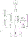
Figure 5 shows an electrical schematic of the power supply, power switch and communication channel between the WPC transmitter and receiver.
Figure 6 shows an electrical schematic of a WPC receiver.
Figure 7 shows inductive power transfer between WPC cells as a function of lateral misalignment and separation distance.
Figure 8 illustrates an alternative RF communication link between a WPC transmitter and a WPC receiver that is capable of transmitting any number of RF signals over two RF communication channels.
Figures 9A-9C show a WPC receiver mounted to a sled by a mechanism that improves time averaged power transfer from the WPC transmitter.
Figure 10 shows a lift car connected to a side shift fork positioning member operated using a WPC transmitter and receiver.
Fig. 11 shows a circuit diagram of the side shift fork positioning member of fig. 9.
Figure 12 schematically illustrates a system including a lift car attached to an accessory, such as a pod clamp accessory, that operates using a WPC transmitter and receiver to transfer data from the accessory to the lift car and to be used by the lift car to control the accessory.
Figures 13 and 14 illustrate a box clamp accessory that may be used with the system of figure 12.
Fig. 15 shows a circuit diagram of the box clamp accessory of fig. 12.
Detailed Description
As mentioned above, designing a control system for operating an electromechanical device on an accessory of an industrial vehicle is challenging and often involves balancing competing considerations, such as eliminating wired electrical connections on the pole, which over time tend to degrade with use of a battery on the accessory, which unfortunately requires frequent charging and/or replacement. Furthermore, the use of a battery mounted to the accessory requires the use of wireless control signals to communicate between the lift car and the accessory, which as previously mentioned tends to confound the lift car with the transmitter, given that the lift car will require the communication of a large number of types of control signals, each accessory having its own unique set of functions as many different types of accessories are attached to the lift car over time. This can be problematic because the lift car may not have a large amount of space for an excessive number of transmitters, especially given that the lift car needs to move between and around many obstacles in an industrial environment, and positioning many transmitters outside the lift car increases the likelihood of damaging the transmitters due to collisions with other objects.
Referring to fig. 3, a novel multifunctional Wireless Power and Communications (WPC) unit 110 is capable of wirelessly transferring power between a host vehicle 112 and an accessory (not shown) mounted to a trolley 114 that is vertically slidable along a mast 116 of the host vehicle. The host vehicle may be, for example, an industrial lift truck, or may alternatively be a work vehicle or any other type of movable industrial equipment to which accessories may be selectively attached and detached. Although the disclosed features of the WPC unit 110 will be described throughout this specification by reference to exemplary interactions between industrial lift trucks and lift truck accessories, those skilled in the art will appreciate that the WPC unit 110 is readily adapted for use in many other applications, such as construction, materials handling, robotics, and the like. It should also be appreciated that while fig. 3 illustrates the WPC power transmitter 118 and the WPC receiver 120 mounted to the host vehicle 112, other embodiments may selectively mount the WPC power transmitter to the host vehicle 112 while mounting the WPC power receiver 120 to accessories, as appropriate for the application and/or design.
The first function of the WPC unit 110 is to wirelessly transmit power from a power source on the host vehicle 112 to an accessory that is movably mounted to the host vehicle 112 by a sled 114 or other structural member of the host vehicle 112. For example, the WPC unit 110 may include a WPC power transmitter 118 rigidly mounted to the host vehicle 112 and capable of inductively transmitting power to a WPC power receiver 120 mounted to the sled 114 of the host vehicle. The term "inductive transfer" of power refers to the transfer of power by induction between two objects that are not in contact with each other. Preferably, the power received by the WPC power receiver 120 may be used to directly power electromechanical functions on the accessory. In other embodiments, the power received by the WPC power receiver 120 may be used to directly power electromechanical functions on the accessory and to recharge a battery on the accessory, such that the battery may be used to also power electromechanical functions on the accessory during time intervals when the power received from the WPC power transmitter 118 is insufficient to fully operate the accessory. For example, as can be seen in fig. 3, the WPC power transmitter 118 and the WPC power receiver 120 may not always be aligned for inductive power transfer when the sled 114 is vertically slid relative to the host vehicle. In other embodiments using other host vehicles and/or accessories, the WPC power transmitter 118 and the WPC power receiver 120 may be out of alignment due to rotating panels, load transfer surfaces, or horizontally moving surfaces (e.g., load push-pull accessories).
In these latter embodiments, in some cases, the battery may be used to add or replace power received by the WPC power receiver 120 as necessary to operate an electromechanical or electrical device on the accessory. In other cases, the WPC unit 110 may be used to recharge the battery on the accessory, which in turn may power all of the electrical and electromechanical devices on the accessory. In some embodiments, a power management controller located within the WPC power receiver 120 or some other location is used to provide power to the WPC power receiver from (1) only the WPC power transmitter 118; (2) from the battery on the accessory only; and (3) from the WPC power transmitter 118 and batteries on the accessories; seamless switching power to the accessory device and using power from the WPC power transmitter 118 to recharge the battery on the accessory when full power from the WPC power transmitter 118 is not required to power the device directly on the accessory.
A second function of the WPC unit 110 is to transmit RF input/output (RF/IO) signals between the host vehicle 112 and accessories. The RF/IO communication channel allows contactless bidirectional signaling and/or power switching between the host vehicle 112 and accessories and thus can be used not only to signal or cause a change in the state of a sensor or switch but also as an output, but also preferably to directly power a responsive device such as a solenoid, relay, light, horn or other device. Preferably, the RF/IO channel is provided within the circuitry of the WPC cell 110. For example, the WPC power transmitter 118 may communicate the switching control signals to the accessories via the WPC power receiver 120, which in turn communicates these signals to provide to various solenoid switches/valves on the accessories. As another example, the WPC power receiver 120 may communicate RF/IO signals from the accessories to the WPC power transmitter 118, which the WPC power transmitter 118 in turn relays to the host vehicle 112. Such a signal from the accessory back to the host vehicle may be useful, for example, to alert the operator when the operation is complete or the accessory is in the correct position by turning on an indicator or energizing a solenoid for function control. The WPC unit 110 may provide any desired number of RF/IO channels in each direction between the host vehicle 112 and the accessories. In a preferred embodiment, the WPC unit includes two dedicated RF input channels and two dedicated RF output channels between the power transmitter 118 and the WPC power receiver 120. It will be appreciated that in each direction, the number of channels per channel may be varied as required to suit the application.
The third function of the WPC unit 110 is to transmit CAN bus (for controlling local area network) communications between the host vehicle 112 and accessories. The CAN bus standard is a two-way message based protocol designed to allow microcontrollers and devices to communicate with each other in a vehicle without a host computer. The CAN bus communication between the host vehicle 112 and the accessories may be used, for example, to transmit barcodes, sensor data, etc. from the accessories back to the host vehicle 112. As another example, the WPC power receiver 120 may communicate analog signals from the accessories to the WPC power transmitter 118, which in turn relays these signals to the host vehicle 112 or an on-board controller. Such an RF signal from the accessory back to the host vehicle is useful, for example, when appropriate hydraulic line pressure or hydraulic flow rate based on sensor readings is taken on the accessory side.
Preferably, the CAN bus communication channel has a continuous transmission range of no less than thirty feet between the WPC power transmitter and the WPC power receiver. The CAN bus communication channel preferably allows for selective transmission of a user specified address or series of addresses to optimize performance. Those of ordinary skill in the art will appreciate that WPC unit 110 may use other network protocols instead of or in addition to CAN communication. For example, according to the complexity of an application to be controlled by the WPC unit 110, a network protocol such as bluetooth, an ethernet protocol, HTTP, SMS, or the like may be used.
To facilitate the transfer of power signals, RF/IO signals, and CAN bus signals between the host vehicle 110 and accessories, each of the WPC power transmitter 118 and the WPC power receiver 120 includes connectors 124 and 126, respectively. For example, the WPC power transmitter 118 preferably includes a power connector 124a connectable to a power source on the host vehicle 112, an RF/IO connector 124b, and a CAN bus connector 124 c. Similarly, the WPC power receiver 120 preferably includes a power connector 126a connectable to a battery on the accessory, an RF 110 connector 126b, and a CAN bus connector 126 c. Each of these connections will be discussed later in this specification.
Each of the WPC power transmitter 118 and the WPC power receiver 120 preferably has a form factor designed to protect each within a protected area of the host vehicle 110 and/or accessories. For example, as can be seen in fig. 3, the WPC unit 110 may be conveniently positioned over the front wheels 122 of the host vehicle 112, and at locations where the WPC unit does not extend laterally beyond the wheels, to minimize the possibility of damage to the WPC unit 110, which is typical of an industrial environment (e.g., warehouses, cargo yards, etc.) when the host vehicle 112 moves between and around objects within a narrow range. In a preferred embodiment, each of the WPC power transmitter 118 and the WPC power receiver 120 is generally circular in cross-section, having a diameter of about 145mm and a width of about 37 mm. It should be understood that in other embodiments, other suitable geometries and/or dimensions may be used.
Furthermore, the size of the WPC power transmitter 118 and the WPC power receiver 120, and their respective positioning on the host vehicle 112 or an accessory, preferably does not substantially impede the load carried by the accessory, which is feasible to position proximate to the sled 114 of the host vehicle 112. In particular, when loading cargo on an accessory to a host vehicle, the front-to-back weight distribution of the load is a limiting factor in how much weight the accessory can safely carry without unbalancing the host vehicle 112. Thus, as shown in fig. 3, locating both the WPC power transmitter 118 and the WPC power receiver 120 behind the trolley of the host vehicle advantageously does not reduce the load carrying capacity of the accessories, which would otherwise be the case if the WPC power receiver were located on or in front of the trolley 14, or on the accessories, for example.
Fig. 4 generally illustrates the structure of each of the WPC power transmitter 118 and the WPC power receiver 120, each including a housing 130 and a cover 132. Each of the housing and the cover may be made of any suitable material, such as carbon fiber or other hard plastic that does not affect inductive transmission between the WPC power transmitter 118 and the WPC power receiver 120. Nested within the housing 130 is a coil wire 134 that provides inductance when carrying current. In a preferred embodiment, as shown in FIG. 4, the wire 134 is wound in a single spiral. Alternate embodiments may wind the wire around multiple spirals, if desired. In still other embodiments, particularly where the WPC cell 110 is not circular in cross-section, the wire 134 may be wound in a spiral of different geometry, such as square, hexagonal, etc.
Separated from the coil leads 134 by a plastic spacer 142 is a circuit board 136 that includes circuitry 138 for communicating RF/IO signals between the WPC power transmitter 118 and the WPC power receiver 120, as well as circuitry for communicating CAN bus signals and implementing a power management module 150 described in more detail later in this specification. It should be understood that fig. 4 only schematically shows the respective CAN circuitry 140, RF/IO circuitry 138 and power management module 150, and that certain circuits may be integrated together and share components.
Accordingly, fig. 5 illustrates the configuration of the RF/ IO connections 124b and 126b of the WPC power transmitter 118 and the WPC power receiver 120 in more detail. In particular, the RF/IO connection 124b on the WPC power transmitter 118 includes a 12V connector for connecting to an external truck-mounted load or other device that may operate on truck power, two RF inputs for receiving signals from local devices to be transmitted to the WPC power receiver 120, and two RF outputs from the signal input at the WPC power receiver 120. In other embodiments, more RF inputs and/or outputs may be provided. The RF/IO connection 126b of the WPC power receiver 120 in turn comprises a 12V load line for connection to accessory mounted devices, two RF inputs for receiving signals from local devices to be sent to the WPC power transmitter 118, and two RF outputs from the signal input at the WPC power transmitter 118. In other embodiments, more RF inputs and/or outputs may be provided. Each of the CAN bus connections 124c and 126c includes CAN high and low connections. The power connection 124a of the WPC transmitter 118 includes a 12V + terminal for power provided by the host vehicle 10 and a ground terminal, and the power connection 126a of the WPC receiver includes a connection to each of the positive and negative terminals of the battery on the accessory.
Inductive power transfer and power management
As previously described, the WPC unit 110 includes the WPC power transmitter 118, the WPC power transmitter 118 having a coil 134, the coil 134 being capable of inductively (i.e., wirelessly) transferring power to a similar coil 134 on the WPC power receiver 120. Preferably, the WPC unit 110 is designed to be able to directly power devices on the accessories of the host vehicle 112, meaning that the devices on the accessories can be operated using power received from a battery or other power source on the host vehicle 112 without the need to simultaneously use power from a battery remotely mounted on the accessories. However, as shown in fig. 3, the WPC power transmitter 118 and the WPC power receiver 120 may not always be in an aligned position to provide sufficient power when needed, or the instantaneous power demand on the accessory may exceed the power transfer capability of the inductive link between the WPC power transmitter 118 and the WPC power receiver 120. To address this situation, in a preferred embodiment, the battery on the accessory to the host vehicle 112 is also able to provide sufficient power to operate the device on the accessory.
Figure 6 illustrates circuitry in the WPC power receiver 120 for managing power provided by the WPC power transmitter 118 and one or more batteries 154 to operate a preferred system of devices on the accessory to seamlessly switch (1) only inductively supplied from the WPC power transmitter 118; (2) supplied only from the battery 154 on the accessory; and (3) from the WPC power transmitter 118 and battery 154; power to the accessory device and when power from the WPC power transmitter 118 is not needed to directly power the device on the accessory, inductive power from the WPC power transmitter 118 is used to recharge the battery 154 on the accessory.
In particular, the receiver-side circuit board 136 of the WPC power receiver 120 may preferably include a power management module 150 that may receive inductive power from a connection 152 on the circuit board 136 to the coil 134 in the WPC power receiver 120, and may also receive power from a connection to a battery 154 on the accessory 12 through a connection 126a (also shown in fig. 3). Both the connection to the battery 154 and the connection 152 from the induction coil 134 are provided as inputs to a control device 156, which control device 156 outputs power to a load 158 on the accessory, which may include, for example, a sensor array, a bar code reader, or the like. The control device 156 also energizes the GP output channel 164, and the GP output channel 164 may be connected to, for example, a solenoid array, lights, or other devices. Those of ordinary skill in the art will recognize that in some embodiments, the control device 156 may be integrated into the power management module 150.
In a preferred embodiment, the maximum induced current and power provided from the WPC power transmitter 118 to the WPC power receiver 120 is approximately 1 amp and 12 watts of power, respectively. Referring to fig. 7, the inductive power provided decreases as a function of misalignment between the opposing surfaces of the WPC power transmitter 118 and receiver 120. For example, in the situation shown in figure 3, where the WPC power receiver is slid vertically relative to the WPC power transmitter, the inductive power transfer is gradually reduced to a misalignment of about 12mm (the maximum shown on the vertical axis at the y origin), then falls off sharply. Similarly, when the WPC unit 110 is installed on the host vehicle 110 and/or the accessory 12, during operation, the WPC power receiver 120 moves laterally away from the WPC power transmitter 118 (e.g., push-pull accessory), the power transfer gradually drops to about 25mm separation and then drops sharply. Figure 7 also shows how the inductive power is reduced as a function of angular misalignment between the inductive surfaces of the WPC unit 110, which may occur, for example, with a tilter application.
The power management module 150 preferably only powers the load 158 from the inductive power connection 152 unless the load 158 requires more power than can be inductively provided from the WPC power transmitter 118 when, for example, the inductive surface of the WPC unit 110 is misaligned or greater than about 1 amp or 12W of power required by the load 158. When this occurs, the power management module seamlessly draws additional power from the battery 154 to meet the requirements of the load 158. Alternatively, when the power demand of the load is less than 1 amp and 12W of power, and the inductive power from the WPC power transmitter 118 is greater than the power demand required to meet the load 118, then the excess power is used to recharge the battery 154 on the accessory.
CAN bus communication
As shown in fig. 6, circuit board 136 on WPC power receiver 120 includes CAN module 160, such as circuit board 136 (not shown) on WPC power transmitter 118, and is connected by CAN connectors 126c and 124c, respectively. The CAN bus standard is a two-way message based protocol designed to allow microcontrollers and devices to communicate with each other in a vehicle without a host computer. CAN is a multi-master serial bus standard for connecting electronic control units [ ECUs ], also referred to as nodes, which may be devices such as sensors, actuators and control devices located on the host vehicle 112 or accessories. The CAN standard requires that each node include a host processor, a transceiver and a CAN controller. Preferably, the circuit board 136 on each of the WPC power transmitter 118 and the WPC power receiver 120 includes circuitry that allows CAN messages to pass seamlessly between the WPC power transmitter 118 and the WPC power receiver 120 through their own CAN connectors 124c and 126c from the ECU connected to each. The respective host processor and CAN controllers for the host vehicle and accessories may be stored locally on each of these structures, with the circuit board 136 on each of the WPC power transmitter 118 and receiver 120 providing only transceiver functionality.
The CAN bus communication between the host vehicle 112 and the accessories may be used, for example, to transmit bar codes, sensor data, etc. between the accessories and the host vehicle 112. Preferably, the CAN bus communication channel has a transmission range between the WPC transmitter and the WPC power receiver that is continuous of no less than thirty feet.
In many embodiments, the CAN communication network may include data representing status information for a very large number of components on the host vehicle and on the accessories. Most of this CAN communication may be unrelated to the communication signals between the host vehicle 112 and the accessories necessary for hydraulic control of the accessories, but will typically be present in the communication channel between the WPC transmitter 118 and the WPC receiver 120, occupying bandwidth, and potentially interfering with control signals to and from the accessories and the host vehicle 112. Thus, in a preferred embodiment, WPC unit 110 includes a list of CAN addresses associated with hydraulic control of accessories, and filters out CAN communications originating from addresses not on the list to optimize performance.
RF input/output communication
Still referring to fig. 6, the circuit board 136 on the WPC power receiver 120 preferably includes two RF inputs 162 to receive data from local sensors, switches or similar devices on the accessory to which the power receiver 120 is electrically connected. The circuit board on the WPC power receiver 120 also preferably includes two RF outputs 164 to receive RF data from the WPC power transmitter 118. Referring to fig. 5, the RF input 162 may be connected to a selectively available RF data source through terminals 2 and 5 of the RF/IO connector 126b, respectively, for communication to the WPC power transmitter 118, while the RF output 164 may be connected to a desired load on the accessory through terminals 3 and 4 of the RF/IO connector 126b, respectively.
When the RF output 164 receives a signal from the WPC power transmitter 118 to activate one or more solenoids, for example, when applicable, the power management module provides power through terminals 3 and/or 4 for switching to the solenoid's signal, and also provides power from the control device 156 through load terminal 1 to actuate the solenoid as directed by the switching signal. In a preferred embodiment, the power management module is configured, through control 156 and using inductive power connections 152 and batteries 154, to provide a maximum of 3 amps per channel and a maximum sum of 5 amps per channel total power to each RF output channel 162. Those skilled in the art will appreciate that more power may be provided per channel and/or overall, depending on the desired application and the amount of power available from the sensing channels in the WPC unit 110 and the battery 154 on the accessory.
Those of ordinary skill in the art will appreciate that fig. 6 schematically illustrates RF circuitry for the WPC power receiver 120, with similar circuitry present in the WPC power transmitter 118. That is, the WPC power transmitter 118 may include two RF inputs that receive control signals intended for transmission to the WPC receiver's RF output 164 to operate a load or other device on the accessory. Similarly, the WPC power transmitter 118 may include two RF outputs that receive signals from the RF input 162 of the WPC power receiver 120.
As can be seen from fig. 6, the power output of the WPC power receiver 120 is preferably capable of providing power to the load 158 over the entire range of operating conditions of the accessory, regardless of the relative position of the WPC power receiver 120 with respect to the WPC power. For example, if the WPC power transmitter 118 and receiver 120 are in optimal alignment, RF power up to 1 amp and 12 watts may be provided inductively while the battery is also recharging. If more RF power is needed with the WPC power transmitter 118 and receiver 120 in optimal alignment, the power management module 150 may draw on the battery to provide power up to 3 maximum amps per channel and a total of 5 maximum amps (or other applicable limit, depending on the application). Furthermore, if the WPC power transmitter 118 and receiver 120 are not in optimal alignment, or even too much, such that inductive power is not provided to the WPC power receiver 120, the WPC power receiver may still provide a maximum of 3 amps per lane and a maximum of 5 amps total to the load 158.
The WPC unit 110 as shown in figures 3-6 is capable of providing four independent RF channels, two in each direction, simultaneously between the WPC power transmitter 118 and receiver 120. FIG. 8 illustrates one example of an alternative embodiment that is capable of using these four independent channels to control a greater number of devices that may be present on the accessories and/or the host vehicle 112. In particular, the host vehicle may be able to transmit a large number (six as shown in fig. 8) of independent RF signals to the accessories, with each RF signal being assigned its own unique frequency band. In some embodiments, respective frequency bands of the RF signal may be separated by guard bands to prevent signal interference therebetween. Each of these signals may be output to a selected one of two independent RF channels 172 to be transmitted to the WPC power receiver. In the event that more than two signals 170 attempt to be sent simultaneously over only two independent channels available, a controller (not shown) may schedule transmissions to avoid collisions. Signals propagating into the WPC power transmitter 118 along RF path 172 are wirelessly transmitted to the WPC power receiver 120, where each signal is in turn propagated along a corresponding RF path 174 to a multiplexer 176, which sends each signal to a series of bandpass filters 178. The band pass filters 178 each have a frequency range corresponding to a particular solenoid or other RF operated device being controlled using the corresponding frequency band 170. Basically, each band pass filter 178 rejects any signals that do not have a frequency corresponding to the device to which it is connected. In this manner, any desired number of functions may be implemented between WPC power transmitter 118 and receiver 120 through wireless RF signaling by sequentially transmitting those signals on respective ones of independent RF channels 172 and 174 as desired.
Sleep mode
In some embodiments, it may be desirable to reduce power draw from a battery on an accessory of the WPC power receiver 120 during times when the WPC power transmitter 118 is powered off and cannot provide inductive power and/or signaling. Thus, the circuit board 136 may include "sleep mode" circuitry capable of: (1) turning off all power output from the WPC power receiver 120 during the time interval when no inductive power is received from the transmitter and no switching signal is received from the WPC power transmitter 118; (2) providing low power to the RF circuitry to periodically sample the RF channel between the WPC power transmitter 118 and the WPC power receiver 120; and (3) wake the WPC power receiver 120 from the sleep mode to provide output power to the accessory. In some embodiments, an accelerometer may be included in the WPC power receiver 120 that detects vibration, indicating that the primary truck is powered on, and thus the WPC power transmitter 118 may be used to provide inductive power and RF data communications.
For example, in some embodiments, the WPC power receiver may be configured to wake up from sleep mode either (1) when vibrations are detected by an incorporated accelerometer, (2) when inductive power is received from the WPC transmitter 118, or (3) when an RF signal is detected by sampling the RF channel between the WPC power transmitter 118 and the WPC power receiver 120. Alternatively, the sleep mode may be initiated when no inductive power and switching signals are received from the WPC transmitter 118.
Time-averaged inductive power transfer maximization
As previously mentioned, and with particular reference to fig. 7, the amount of inductive power transfer between the WPC power transmitter 118 and the WPC power receiver 120 is sensitive to the alignment between the two units. Figures 9A to 9C illustrate one embodiment of the mounting mechanism that allows the sled 114 of the host-vehicle 112 to move relative to the host-vehicle 112 over a preselected distance without simultaneously moving the WPC power receiver 120 relative to the WPC power transmitter 118.
In particular, the WPC power transmitter 118 may be mounted to the frame of the host vehicle 112 using a transmitter bracket 186, the transmitter bracket 186 extending parallel and away from the bottom surface of the WPC power transmitter 118. The WPC power receiver 120 may be mounted to the sled 114 of the host vehicle 112 using an assembly including a skid rail 180, a sleeve 190, and a bracket 188. In particular, the bracket 188 includes a vertical portion rigidly secured to the back of the WPC power receiver 120, and a horizontal portion on which the WPC power receiver 120 rests. The sleeve 190 slidably engages the track 180 and is rigidly secured to the vertical portion of the bracket 188. The track 180 is in turn rigidly secured to the trolley 114.
In the rest position shown in fig. 9A, with the WPC power transmitter 118 and receiver 120 in optimal alignment and the trolley 114 in its lowest position, the horizontal portion of the cradle 188 rests on top of the cradle 186 preventing downward movement of the WPC power receiver 120 relative to the WPC power transmitter 118. As shown in fig. 9B, when the sled is lifted upwards, the track 180 may slide in the sleeve 190 while the WPC power receiver 120 remains in place due to its weight. However, attached at the base of the track 180 is a block 184 that eventually catches the protruding portion of the bracket 188 as the trolley continues to move upward and thereby lifts the WPC power receiver 120 out of alignment, as shown in figure 9C. Conversely, as sled 114 is lowered back to the rest position of fig. 9A, the weight of WPC power receiver 120 causes it to follow a downward path until rack 188 catches on rack 186.
As seen in fig. 9A-9C, this novel arrangement allows the sled 114 to move a distance greater than the diameter, height, width, or other suitable dimension of the WPC unit 110 relative to the host vehicle's pole while still providing inductive power between the WPC power transmitter 118 and the WPC power receiver 120. In other words, the disclosed structure allows the sled 114 of the host vehicle 112 to move throughout a range of motion (vertical, horizontal, inclined, etc.) without reducing or otherwise inhibiting the ability of the WPC transmitter 118 to provide inductive power to the WPC receiver 120 and by extending to and/or operating the device from a battery on the accessory.
In a preferred embodiment, the length of the slide rail is no less than 12 inches. The inventors have determined that in this range, for example, during normal operation of a Hi/Lo tank clamp application, the WPC power transmitter 118 and receiver 120 are in optimal alignment for more than 80% of the time, and this configuration eliminates the need to replace the batteries. However, it should be understood that other uses may require different lengths of track. It should also be understood that fig. 9A-9C are merely exemplary, as the different configurations may also allow for a range of travel of the sled of the host vehicle 10 without corresponding relative movement of the WPC power transmitter 118 and receiver 120 from their optimal alignment. For example, when in a "tipping" load, it may be more appropriate for the curved track 180 to rotate 90 degrees along the vertical axis from that shown in fig. 9A to 9C when the trolley is tipped off of the lift car's tipping application.
As can be seen in fig. 9A-9C and also with reference to fig. 6 and the preceding paragraph 0051-0055, the disclosed WPC unit 110, in combination with the mounting mechanism just disclosed, allows the devices on the accessory to receive power as needed and without interruption during the full operating range of the accessory while significantly maintaining a state of charge on the accessory's battery. For a significant portion of the time that the accessory is in use, the attachment-side device may be powered using inductive power received directly from the host vehicle. Furthermore, by also routing battery power through the WPC receiver 120, the power management module 150 can seamlessly draw on the accessory's battery to power these devices when inductive power is insufficient — either because more power is required than is delivered inductively, or because the WPC power receiver 120 is no longer aligned with the WPC power receiver 118 if the accessory moves beyond the range where the mounting mechanism maintains alignment with the WPC unit 110.
In other words, the disclosed mounting mechanism greatly increases the time when the connection-side device can operate without drawing power from the battery on the accessory. However, by also routing power from the accessory's battery through the WPC receiver 120, the power management module 150 can ensure that those connection-side devices do not see any power interruption even when inductive power from the WCP transmitter 118 is interrupted or when load demand increases beyond what can be provided inductively. During such intervals, the power management module 150 may seamlessly draw power from the accessory's battery as that power is transferred to the load on the same channel as the inductive power from the WPC power transmitter 118. Furthermore, when the accessory is moved to bring the WPC power receiver 120 back into alignment with the WPC power transmitter 118, inductive power may again be used to seamlessly and uninterruptedly directly power the attachment-side device, thereby reducing or eliminating draw on the accessory battery, and thus the battery may be recharged.
One of ordinary skill in the art will appreciate that while the disclosed mounting mechanism for the WPC unit 110 provides the benefits of maintaining an aligned relationship between the WPC power transmitter 118 and the WPC power receiver 120 as the sled and/or accessories move relative to the host vehicle, in some embodiments, the disclosed mounting mechanism may be omitted while still retaining the benefits associated with the WPC unit 110, such as seamless power switching between induction/battery power, etc.
Application of side shift fork positioning piece
Fig. 10 schematically illustrates a side shift fork positioning member attachment 210 to the host vehicle 112. The host vehicle 112 (lift car) includes the WPC power unit 110, and the WPC power unit 110 includes the transmitter 118 and receiver 120 as previously described and is used to transmit power from the vehicle battery 154 and RF control signals from the manual actuator 214 to the electromagnetic selector valve array 216. Although the solenoid selector valve array 216 is shown mounted on the carriage in fig. 10, it may alternatively be mounted on the attachment. Similarly, although figure 10 shows WPC receiver 120 directly connected to selector valve 216 on sled 214, other embodiments, such as those with a controller mounted on attachment 210, may have output connections from WPC receiver 120 all connected to attachment 154, with other connections (not shown) from the attachment to selector valve array 216. Pressurized hydraulic fluid is delivered to the selector valve array 216 via two hydraulic lines 260, 262 (only one of which is shown in fig. 10).
FIG. 11 is a schematic circuit diagram of an exemplary wireless hydraulic control system that may optionally be used for side-shifting fork positioning member 210. However, this type of system may also be applied to side-shifting load clamps, particularly one having parallel sliding clamp arms. The hydraulic circuit as shown in fig. 11 enables the lift truck operator to separately control the side-shift function and the fork positioning function using a single control valve 264 on the body with a handle 264a having an electrical switch 264b mounted on the handle 264 a. The individual pairs of hydraulic lines 260 and 262 communicate between the lift car 112 and the vertically movable load handler 210 by extending over the lift car's mast 116, employing a line receiving device such as a conventional hose reel to accommodate the variable vertical position of the load handler relative to the lift car body.
In the circuit of fig. 11, the engine-driven hydraulic pump 268 of the lift truck 112 pumps hydraulic fluid under pressure from a reservoir 270 through a line 272 to the operator's control valve 264. Relief valve 274 provides protection against excessive pressure in line 272. If the operator manually moves the spool of valve 264 downward from its center position as shown in FIG. 11, pressurized fluid from line 272 is conducted through line 262 to the solenoid-operated hydraulic selector valve 276 of the load handler in valve array 216 shown in FIG. 10. The spool of valve 276 is spring biased upward as shown in fig. 11 so that fluid in line 262 operates the first hydraulic actuator and function, with fluid being conducted to one end of the side-shifting piston and cylinder assembly 224, moving the piston to the left as shown in fig. 11, while fluid is simultaneously discharged through line 260 and valve 264 to reservoir 270. Alternatively, if the operator wishes to side shift in the opposite direction, he manually moves the spool of valve 264 upward, as shown in fig. 11, which conducts pressurized fluid from line 272 to line 260, moving the piston in the opposite direction, while expelling fluid through line 262 and valve 264 to reservoir 270.
If instead of actuating the side-shifting piston and cylinder assembly 224 in one direction or the other, the operator wishes to operate a second hydraulic actuator in the form of fork-positioning cylinders 230 and 232, he controls a second function of the load handler using the same valve 264, while manually closing switch 264b, for example by means of a button on handle 264 a. Closing of switch 264b causes the WPC power transmitter 118 to send an RF signal to the WPC power receiver 120, the RF GP output, which in turn propagates the signal to the GPO switch 156 in the WPC receiver 120.
The GPO switch 156 will respond to the RF signal initiated by the operator closing switch 264b by energizing the solenoid 276a of the function select valve 276 and moving its spool downward as shown in fig. 11 against the force of spring 276 b. This movement of valve 276 places hydraulic line 282 in communication with line 262. If the operator has moved the spool of the valve 264 downward, line 282 retracts the fork-positioning piston and cylinder assemblies 230 and 232 by receiving pressurized fluid from line 262, thereby causing fluid to be discharged from the piston and cylinder assemblies 230 and 232 through line 260 and valve 264 to the reservoir 270. This retraction of the piston and cylinder assemblies 230 and 232 reduces the separation between the forks or fork-positioning load processors 210. Conversely, an operator's upward movement of the spool of valve 264 simultaneously closes switch 264b to conduct pressurized fluid through line 260 to extend the piston and cylinder assemblies 230 and 232 to increase the separation between the forks while fluid is discharged through line 282, valve 276, line 262 and valve 264 to reservoir 270.
As previously described, WPC receiver 120 receives inductive power boosted by battery 154 on the side-shifting fork positioning element when it is desired to operate solenoid 276a and GPO switch 156 and send control signal 156 to the GPO switch.
Application of box clamp
FIG. 12 schematically illustrates the host vehicle 112, the host vehicle 112 being coupled to an accessory 310, which may be, for example, a box clamp accessory. The host vehicle 112 (lift truck) includes a WCP power unit 110, the WCP power unit 110 including a transmitter 118 and receiver 120 as previously described, and also as previously described for transmitting power from the vehicle battery 312, along with any RF control signals needed, to power devices on the accessories 310, and using a manual actuator 314. Pressurized hydraulic fluid is carried to the attachment 310 via two hydraulic lines 360, 362 (only one of which is shown in fig. 12).
Further, the host vehicle 112 is configured to receive one or more signals based on data from the sensor array 316 on the accessory 310 and to control the amount of pressure provided in the lines 360, 362. As described in more detail below, data provided from the sensor array 316 may be provided directly to an optional driver interface controller 318 on the host vehicle that uses the provided data to determine the appropriate line pressure, or alternatively data from the sensor array may be provided to the controller 320.
Figures 13 and 14 show a box clamp 310 that may be used as an accessory in the system shown in figure 12, the function of which will be provided as background to illustrate the utility of the WPC transmitter 118 and WPC receiver 120 used in accordance with the system shown in figure 12. Specifically, the exemplary pod clamp 310 may be a hydraulically powered, slidable arm clamp having a frame 311 (shown in fig. 12) adapted to be mounted on a lift car sled 301, the lift car sled 301 being selectively linearly reciprocable along a conventional tiltable upright hydraulically powered, load-lifting rod 302. The particular exemplary slidable arm clip 310 shown in the figures is generally used to handle prismatic objects, such as boxes or packages 313 in fig. 14, and may be of any suitable slidable arm design. The clamp arms 315, 317 can be selectively slid away from or toward each other perpendicular to the planar or load engaging surfaces 321, 332. Hydraulic cylinders 326, 328 selectively extend or retract the respective clamp arms 321, 332. It will be appreciated that the box, such as 313, may be damaged if it is over-clamped to prevent frictional gripping of the box clamp 310.
Although a hydraulically operated box clamp 310 is described herein as an exemplary embodiment, other load clamps have similar features as described. For example, hydraulically operated pivot arm paper clips may be configured in accordance with the present load clamping system.
The pod clip 310 may include a data receiver, such as an electronic code reader 332 disposed on the clip 310. Thus, the item to be clamped may advantageously be marked with a coded label 334. Coded label 334 may preferably contain a grip strength sufficient to assist in determining an appropriate maximum grip force for marking an article, as will be described below. Coded tag 334 may, for example, transmit a digital data string containing the load ID or other direct or indirect characteristic identifying indicia of the item. The load may include one or more marked boxes or packages 313, so that a suitable clamping force on the individually labeled articles may or may not be appropriate for the entire load. As will be described later, embodiments of the present system make this determination using a communication channel between the WPC transmitter 118 and the WPC receiver 120.
The electronic code reader 332 is positioned to read the coded tag 334 on at least one article that constitutes the load of the load handling fixture 310. The electronic code reader 332 may operate automatically, for example by searching for a coded tag whenever the gripper arms are in an open position or whenever a load is detected between the gripper arms, as will be described in more detail below. Alternatively, the electronic code reader may be manually operated by the clip operator. Coded tag 334 and electronic code reader 332 may be a bar code and bar code scanner, a Radio Frequency Identification (RFID) tag and RFID reader, respectively, or other machine-readable tag and corresponding reader combination. In the case of an RFID system, the RFID reader of the clamp may be constrained such that it only detects RFID tags disposed between the clamp arms 315, 317. Alternatively, the load ID or other loading indicia may be entered by the clamp operator, for example, when the coded tag is rendered unreadable in some manner, or if the tag of an item is incorrect.
The electronic code reader 332 sends the information read from the coded tag 334 to a controller, which may be the controller 320 shown in FIG. 12 on the accessory 310 (pod holder) or the controller 318 on the host vehicle 112, depending on the configuration of the system shown in FIG. 12, and as will be described later in this specification. The controller 320 (or 318) parses the information to identify the load ID or other identifying indicia. This is accomplished in any manner required by the particular implementation of the particular embodiment of the present system being used.
When the clamping arms 15,17 are in the open position, the arms partially define a three-dimensional clamping area. To clamp a load, the clamp operator positions the clamp arms 15,17 so that the load is disposed in the clamping area. The load geometry sensor 350 is in data communication with the controller 318 or 320 and is disposed on the respective load engaging surface 321, 332. The load geometry sensor 350 is generally oriented inwardly in the direction of the opposing surfaces 321, 323.
Each load geometry sensor 350 absorbs and dynamically modulates a characteristic of the communication medium between it and the controller 318 or 320 as a function of the absorbed stimulus. In certain embodiments of the present system, the sensor 350 may be, for example, an infrared beam sensor, such as the GP2XX series of IR infrared beam sensors commercially available from Sharp corporation.
Examples of such sensors include transmitter components, detector components, analog outputs, and internal circuitry. The sensor emits an Infrared (IR) beam. The IR beam travels through the clamping area until it encounters an obstruction, such as an interfering surface of a load, or an opposing load-engaging surface in the absence of a load. Preferably, but not necessarily, the interference surface is parallel to the load engaging surface and the light beam is emitted in a plane perpendicular to the load engaging surface. The IR beam is reflected by the surface and at least partially absorbed by the detector component. Within the sensor, internal circuitry measures the angle between the sensor and the absorbed infrared light, and by triangulation, uses this angle to further calculate the distance between the sensor and the interfering surface, and represents this distance as an analog voltage. The sensors communicate the calculated distance information to the controller 40 via analog outputs.
With further reference to fig. 13, in one illustrated exemplary embodiment, the sensors 350 may be arranged in a grid array of rows and columns. When the space between the clamp arms 321, 323 is not occupied, the stimulus output by all sensors will be comparable to the distance between the clamp arms. However, when a load of article 313 is inserted between clamping arms 321, 332, the signal from at least one load geometry sensor 350 will change. The controller 318 or 320 may then calculate an approximate volume of the load. The number of rows and columns of load geometry sensors whose signals indicate the presence of a load correspond to the height and depth of the load, respectively, and the magnitude of the change in the signal from the obstructing sensor corresponds to the width of the load relative to the signal produced when the sensor is not obstructed. Alternatively, sensors 350 may be arranged in any other suitable type of array.
At least one of the load geometry sensors 350 may also be used as a load proximity sensor. As described below, during a clamping operation, the present system advantageously adjusts the maximum hydraulic clamping pressure as a function of the distance between the clamp arm and the load so that the desired clamping pressure reaches the desired distance.
Other embodiments of the present system (not shown), such as those intended for use with hydraulically operated pivoting arm clamps for clamping cylindrical objects, may utilize different sensor arrangements for measuring load geometry. For example, the diameter and height of the cylindrical load may be determined in the same manner as described above. By way of non-limiting example, the diameter of a cylindrical load (not shown) may alternatively be determined by measuring the stroke of a hydraulic cylinder (not shown) when the clamp arm contacts the load, but before clamping the load, using a string potentiometer (not shown) or an etched rod and optical encoder (not shown) in conjunction with other sensors.
In an exemplary embodiment of the present system, the controller 318 or 320 may access a memory (not shown) containing information corresponding to the preferred operation of the clamp when clamping and lifting various load types and their geometries, preferably arranged in a look-up table organized by load category and load geometry. This information may be a characteristic, such as load weight, load fragility, load packaging, etc., preferably closely related to the optimal maximum clamping force, or optimal maximum hydraulic clamping pressure. For each load class, the data is further preferably classified according to the potential geometrical configuration of the detected load class.
In some embodiments, the data may be statically stored at a location remote from the host vehicle 112 and/or the accessory 310, such as in a central management system or off-site database of the facility, and the controller 318 or 320 may be accessed over an internal and/or external network or networks. In determining relevant load characteristics (e.g., load class and geometry), the controller may copy the necessary data from an external source into memory.
The data in the memory may be specific to the loads and load geometries that the fixture may encounter at the facility in which it operates. Data can be updated by the data receiver as required; for example when a new class of load is introduced into the facility or when some aspect of the current data is deemed insufficient or inaccurate.
As described above, the present system may obtain the load ID or other identification indicia of the load 313 to be clamped by reading the coded tag 334 on the load. Alternatively, such load IDs or other identifying information may be obtained by other types of data receivers, either directly from the central management system of the facility or from other load handling clamps via a wireless network interface. As described above, the present system uses load geometry sensors to calculate an approximate volume of the load. Advantageously, both items of information are determined before the gripper arms grip the load, and no input from the gripper operator is required. The controller 318 or 320 looks up the optimum maximum hydraulic clamping pressure for the determined load ID and load geometry profile. The optimum maximum pressure is then applied to the load during the clamping operation.
Referring to fig. 15, the hydraulic clamping cylinders 326, 328 are controlled by a hydraulic circuit, generally indicated in simplified schematic form as 370. The hydraulic clamping cylinders 326, 328 receive pressurized hydraulic fluid from the reservoir 374 of the lift car through a pump 378 and a supply conduit 382. If excessive pressure builds in the system, safety relief valve 386 opens to divert fluid back to reservoir 374. Flow in conduit 382 provides a manually actuated pinch control valve 390, as well as manually operated valves, such as valves (not shown) that control lift, tilt, side shift, etc., which may be arranged in series with valve 390. The pinch control valve 390 is selectively controlled by an operator to cause the air cylinders 326, 328 to open or close the pinch arms to make initial contact with the articles 313 in the load.
To open the clamp arms 315, 317, the spool of the schematically illustrated valve 390 is moved to the left in fig. 15 such that pressurized fluid from line 382 is conducted through line 394 and the diverter/combiner 398 to the piston ends of cylinders 326, 328, thereby extending cylinders 326 and 328 at substantially equal rates and moving the clamp arms 315, 317 away from one another due to the equal flow delivery operation of the diverter/combiner 398. The pilot check valve 402 is opened by a clamp-open pressure in line 394, which line 394 communicates through the pilot line 406, allowing fluid to drain from the rod end of the cylinders 326, 328 to the reservoir 374 through line 410 and valve 390 as the cylinders 326, 328 extend.
Alternatively, to close the clamp arms and clamp the loaded item 313, the spool of valve 390 is moved rightward in fig. 15 such that pressurized fluid from line 382 is conducted through line 410 to the rod ends of cylinders 326, 328, thereby retracting cylinders 326, 328 and moving clamp arms 313, 317 toward each other. Fluid is discharged at substantially equal rates from the piston ends of cylinders 326, 328 to reservoir 374 through flow divider/combiner 398 and then through line 394 via valve 390. During the closing of the clamping arms 313, 317 by retraction of the cylinders 326, 328, the maximum hydraulic closing pressure in line 410 is preferably controlled by one or more pressure regulating valves. For example, such a pressure regulating valve may be a proportional relief valve 414 in line 418 parallel to line 410, such a maximum hydraulic closing pressure corresponding to a different setting automatically selectable by the controller 318 or 320 via control line 422 in a substantially infinitely variable manner, which electronically regulates the relief pressure setting of the valve 414 by variably controlling the valve's solenoid 414 a. Alternatively, a proportional pressure reducing valve may be inserted in line 410 in series to regulate the maximum hydraulic shutoff pressure in line 410. As a further alternative, a plurality of non-proportional pressure relief or pressure reducing valves may be used, optionally for this purpose. The controller 318 or 320 may also receive feedback of clamping force via hydraulic closing pressure from optional pressure sensor 430 to assist it in controlling the pressure regulating valve, if desired. Such feedback may alternatively be provided by a suitably mounted clamping force measuring transducer (not shown).
Referring again to fig. 12, RF and/or CAN bus communication channels between the WPC transmitter 118 and the WPC receiver 120 may be used to advantageously use data received in some devices from the code reader 332 and the load geometry sensor 350 and pressure sensor 430 to control the operation of the pod clamp 310. In the first embodiment, for example, the controller 318 on the host vehicle 112 may receive load geometry data (shown in fig. 5) from the sensors 350 via the CAN bus communication channels 124c, 126c, and may also receive data from the code reader 332 from the CAN bus communication channels. Thus, the controller 318 on the host vehicle may use this information to determine the appropriate clamping pressure, as previously described. Using the CAN channel to communicate sensor and load ID data advantageously allows the RF channel to be used to simultaneously transmit other data back to the host vehicle, which may be useful, for example, to alert the operator when the operation is complete or the accessory is in the correct position by turning on an indicator or energizing a solenoid for functional control.
In an alternative embodiment, the accessory 310 (pod clamp) may include a controller 320, the controller 320 receiving data from the load geometry sensor 350 and the code reader 332 and using the data to determine the appropriate clamping pressure, which is then communicated to the host vehicle 112 from the WPC receiver 120 to the WPC transmitter 118 via one or more RF communication channels (or CAN channels, if appropriate). For example, where the possible clamping pressures are limited to two alternative pressures, a single RF channel may be used to communicate the desired pressure. Alternatively, two RF channels would allow communication up to one of four possible pressures. If more possible pressures are available, a CAN communication channel may be used, more RF channels may be integrated into the WPC unit 110, or a multiplexed system as shown in fig. 8 may be used, depending on the application. As previously described, using the CAN channel to return to the host vehicle communication will allow other information to be simultaneously transmitted to the host vehicle over the RF channel.
It should be understood that the box clamp example just described is for illustrative purposes only, as the possible applications of the WPC unit 110 extend to any accessory that sends data to the host vehicle for proportional control of the accessory using simulation or other feedback more complex than binary switching control through the RF 110 channel as previously described. It should also be understood that the data communicated from the accessory 310 to the host vehicle 112 may be used to automatically control the accessory 310 via the appropriate controller 318 or 320, or alternatively may be used to provide information to the user through a GUI or other display, audio device, or the like, which then responds appropriately through an interface such as a touch screen, keyboard, wand, or any other input device to issue a new command that is similarly sent back to the accessory through the WPC unit 110 and/or the pressure lines 360, 362.
Those of ordinary skill in the art will also appreciate that the arrangement schematically shown in fig. 12 is merely exemplary and may be modified as appropriate. For example, although fig. 12 shows the array of flow and pressure valves mounted on the sled 301, the array may alternatively be mounted on an accessory. Similarly, although fig. 12 shows the WPC receiver 120 directly connected to the valve array on the sled 301, other embodiments may have the output connections from the WPC receiver 120 all connected to devices (e.g., batteries, controllers) on the accessory 310 with other connections (not shown) from such devices to the valve array on the sled 301.
It is to be understood that the invention is not limited to the particular embodiments which have been described and that changes may be made without departing from the scope of the invention as defined in the appended claims, as interpreted according to the principles of law, including the doctrine of equivalents or any other principle which would expand the scope of the claims beyond their literal scope. Unless the context indicates otherwise, reference in the claims to a number of instances of an element, whether one instance or more than one instance is referenced, requires at least the specified number of instances of the element, and is not intended to exclude from the scope of the claims structures or methods having more instances of the element than described. When used in the claims, the word "comprise" or variations such as "comprises" or "comprising", is used in a non-exclusive sense and is not intended to exclude the presence of other elements or steps in the claimed structure or method.
Claims (16)
1. An industrial transport assembly comprising:
(a) a transmitter unit and a receiver unit, the transmitter unit being capable of transmitting radio power to the receiver unit;
(b) the receiver unit has a housing and a first wiring connector extending from the housing and connectable to a power consuming load device outside the housing of the receiver unit and remote from the transmitter unit so that the power consuming load device can receive the radio power when connected, and a second wiring connector extending from the housing and connectable to a power storage means outside the housing of the receiver unit, wherein the first wiring connector is capable of delivering electrical power to the power consuming load device when the receiver unit is not receiving the radio power from the transmitter unit.
2. The industrial transmission assembly of claim 1, wherein the transmitter unit is capable of wirelessly transmitting data to the receiver unit.
3. An industrial transmission assembly as claimed in claim 2 wherein said transmitter unit transmits at least one of RF data and network protocol data.
4. The industrial transmission assembly of claim 1, wherein the receiver unit is capable of wirelessly transmitting data to the transmitter unit.
5. An industrial transmission assembly as claimed in claim 4 wherein said transmitter unit transmits at least one of RF data and network protocol data.
6. An industrial transport assembly comprising:
(a) a transmitter unit and a receiver unit, the transmitter unit being capable of transmitting radio power to the receiver unit;
(b) the receiver unit having a housing and a first wiring connector extending from the housing and connectable to a battery external to the housing of the receiver unit and remote from the transmitter unit, and a second wiring connector extending from the housing and connectable to a power consuming load device external to the housing of the receiver unit and remote from the transmitter unit; wherein
(c) The first wiring connector is capable of recharging the battery using a first portion of the wireless power while the second wiring connector simultaneously delivers a second portion of the wireless power to the power-consuming load device.
7. An industrial transmission assembly as claimed in claim 6 wherein said first wiring connector is capable of receiving electrical power from said battery.
8. The industrial transmission assembly of claim 7, wherein the electrical power received from the battery is capable of powering the power-consuming load device when the power-consuming load device is connected to the receiver unit.
9. An industrial transmission assembly as claimed in claim 8 including a power management control device in said receiver unit which manages the use of said radio power and power from said battery.
10. The industrial transmission assembly of claim 6, comprising an induction coil in the receiver unit.
11. The industrial transmission assembly of claim 10, wherein the induction coil is electrically connected to a power management module that selects whether to send electrical power to the power-consuming load device from the induction coil, from the battery, or from the induction coil and the battery.
12. An industrial transport assembly comprising:
(a) a housing that houses an induction coil capable of receiving wireless power;
(b) an input connector extending from the housing and connectable to a storage device external to the housing to enable wired electrical power from the storage device;
(c) an output connector extending from the housing and capable of connecting and delivering electrical power to a load external to the housing; and
(d) circuitry executing a power management system that directs output power to the output connector, the output power comprising an automatically selected combination of the wired electrical power and the wireless electrical power.
13. The industrial transmission assembly of claim 12, wherein the power management system is capable of selecting only the wireless power to direct to the output connector.
14. The industrial transmission assembly of claim 12, wherein the power management system is capable of selecting only the wired electrical power to direct to the output connector.
15. The industrial transmission assembly of claim 12, wherein the wired electrical power is from a battery.
16. The industrial transmission assembly of claim 15, wherein the power management system can selectively recharge the battery using a first portion of the wireless power while delivering a second portion of the wireless power to the output connector.
Priority Applications (1)
| Application Number | Priority Date | Filing Date | Title |
|---|---|---|---|
| CN201811024255.6A CN109245323B (en) | 2015-02-10 | 2015-10-30 | Wireless power transfer and communication for industrial equipment |
Applications Claiming Priority (3)
| Application Number | Priority Date | Filing Date | Title |
|---|---|---|---|
| US14/618,784 | 2015-02-10 | ||
| US14/618,784 US9935469B2 (en) | 2015-02-10 | 2015-02-10 | Wireless power transfer and communications for industrial equipment |
| PCT/US2015/058476 WO2016130184A1 (en) | 2015-02-10 | 2015-10-30 | Wireless power transfer and communications for industrial equipment |
Related Child Applications (1)
| Application Number | Title | Priority Date | Filing Date |
|---|---|---|---|
| CN201811024255.6A Division CN109245323B (en) | 2015-02-10 | 2015-10-30 | Wireless power transfer and communication for industrial equipment |
Publications (2)
| Publication Number | Publication Date |
|---|---|
| CN107302847A CN107302847A (en) | 2017-10-27 |
| CN107302847B true CN107302847B (en) | 2021-04-27 |
Family
ID=56567149
Family Applications (2)
| Application Number | Title | Priority Date | Filing Date |
|---|---|---|---|
| CN201580075867.6A Active CN107302847B (en) | 2015-02-10 | 2015-10-30 | Wireless power transfer and communication for industrial equipment |
| CN201811024255.6A Active CN109245323B (en) | 2015-02-10 | 2015-10-30 | Wireless power transfer and communication for industrial equipment |
Family Applications After (1)
| Application Number | Title | Priority Date | Filing Date |
|---|---|---|---|
| CN201811024255.6A Active CN109245323B (en) | 2015-02-10 | 2015-10-30 | Wireless power transfer and communication for industrial equipment |
Country Status (8)
| Country | Link |
|---|---|
| US (2) | US9935469B2 (en) |
| EP (2) | EP3591781A1 (en) |
| JP (1) | JP6644801B2 (en) |
| CN (2) | CN107302847B (en) |
| AU (3) | AU2015382381B2 (en) |
| BR (1) | BR112017017204B1 (en) |
| CA (1) | CA2975683C (en) |
| WO (1) | WO2016130184A1 (en) |
Families Citing this family (24)
| Publication number | Priority date | Publication date | Assignee | Title |
|---|---|---|---|---|
| US20180278079A1 (en) * | 2012-01-11 | 2018-09-27 | Wheel Charge Technologies LLC | Apparatus for Wireless Power Transmission Between an External Power Source and an Electric Mobility Vehicle |
| US9935469B2 (en) | 2015-02-10 | 2018-04-03 | Cascade Corporation | Wireless power transfer and communications for industrial equipment |
| US10414359B2 (en) * | 2015-02-16 | 2019-09-17 | Tyri International, Inc. | System for providing wireless operation of powered device(s) on a vehicle |
| US10680678B2 (en) * | 2015-02-16 | 2020-06-09 | Tyri International, Inc. | System for providing wireless operation of powered device(s) on a vehicle with direct charging |
| US9525288B2 (en) * | 2015-02-26 | 2016-12-20 | Cascade Corporation | Devices and methods for inductive power transfer and power control for industrial equipment |
| EP3187455B1 (en) * | 2015-12-29 | 2021-12-01 | STILL GmbH | System comprising industrial truck and battery charging device |
| DE102016102652A1 (en) * | 2016-02-16 | 2017-08-17 | Jungheinrich Aktiengesellschaft | Industrial truck with a light source on the load carrier |
| US10688874B2 (en) * | 2016-06-14 | 2020-06-23 | Intel Corporation | Vehicular inductive power transfer systems and methods |
| US10399449B2 (en) * | 2016-08-08 | 2019-09-03 | Hyundai Motor Company | Wireless charging control apparatus and method for optimal charging by adjusting the inclination of the electric vehicle being charged |
| US10501298B2 (en) * | 2017-04-04 | 2019-12-10 | Tyri International, Inc. | Linear actuator system for moving tines of a work vehicle |
| EP3461673B1 (en) * | 2017-09-27 | 2020-08-05 | Tyri International, Inc. | System for providing wireless operation of powered device(s) on a vehicle with direct charging |
| US11159122B2 (en) * | 2018-06-21 | 2021-10-26 | Ravi Chailertborisuth | Apparatus for charging a handheld computing device |
| CN109193958B (en) * | 2018-09-13 | 2021-01-15 | 京东方科技集团股份有限公司 | Wireless charging device and charging mechanism and electronic system thereof |
| DE102019201599A1 (en) * | 2019-02-07 | 2020-08-13 | Bhs Intralogistics Gmbh | Transfer order |
| AU2020260411A1 (en) | 2019-10-29 | 2021-05-13 | The Raymond Corporation | Systems and methods for a clamp with power and communication contacts |
| CN110730117B (en) * | 2019-11-07 | 2022-04-15 | 三一汽车起重机械有限公司 | Assembled davit and hoist based on CAN bus |
| JP6872000B1 (en) * | 2019-12-16 | 2021-05-19 | 日本航空電子工業株式会社 | Wireless connector attachment / detachment method, robot device and wireless connector |
| JP6872050B1 (en) * | 2020-02-03 | 2021-05-19 | 日本航空電子工業株式会社 | Robot device and wireless connector |
| FI129188B (en) * | 2020-02-24 | 2021-08-31 | Stevenel Oy | Lifting device for pulp units |
| DE102020110481B3 (en) * | 2020-04-17 | 2021-08-12 | Tadano Demag Gmbh | Induction sensor arrangement of a safety and locking unit of a telescopic boom of a vehicle crane |
| JP6995941B1 (en) * | 2020-07-07 | 2022-01-17 | 日本航空電子工業株式会社 | Wireless connector attachment / detachment method, robot device, wireless connector and wireless connector unit |
| EP4119491A1 (en) * | 2021-07-16 | 2023-01-18 | TOYOTA MATERIAL HANDLING MANUFACTURING ITALY S.p.A | Industrial truck capable of recognizing a material handling apparatus |
| IT202100024086A1 (en) * | 2021-09-20 | 2023-03-20 | Bolzoni Spa | SUPPORT AND CONTROL DEVICE FOR AN ELECTRIC BATTERY FOR HANDLING EQUIPMENT OF A FORKLIFT AND HANDLING EQUIPMENT INCLUDING SUCH A DEVICE. |
| US20230249359A1 (en) * | 2022-01-27 | 2023-08-10 | Cascade Corporation | Variable load geometry clamp pressure control |
Citations (5)
| Publication number | Priority date | Publication date | Assignee | Title |
|---|---|---|---|---|
| CN101648524A (en) * | 2009-09-17 | 2010-02-17 | 北京地下铁道车辆技术研究所 | Power supply system of traffic vehicle and management method thereof |
| CN201478885U (en) * | 2009-06-04 | 2010-05-19 | 速得股份有限公司 | Charging device |
| CN103078365A (en) * | 2012-12-26 | 2013-05-01 | 青岛歌尔声学科技有限公司 | Bluetooth headset charging box and charging method thereof |
| CN202997644U (en) * | 2012-12-26 | 2013-06-12 | 青岛歌尔声学科技有限公司 | Bluetooth earphone charging case |
| CN103703651A (en) * | 2011-07-24 | 2014-04-02 | 株式会社牧田 | Power tool system and adapter therefor |
Family Cites Families (28)
| Publication number | Priority date | Publication date | Assignee | Title |
|---|---|---|---|---|
| US3768367A (en) | 1969-05-07 | 1973-10-30 | Caterpillar Tractor Co | Remote control system for load manipulating vehicles |
| US3647255A (en) | 1969-11-14 | 1972-03-07 | Gordon H Hale | Remote-controlled grapple |
| JPS5238323B2 (en) | 1971-12-27 | 1977-09-28 | ||
| US4381872A (en) | 1981-03-26 | 1983-05-03 | Mcginnes Manufacturing Company | Remote controlled clamshell bucket apparatus and method of using same |
| US4526413A (en) | 1984-04-09 | 1985-07-02 | Williams Howard G | Remote controlled self-powered excavator apparatus |
| US6431816B1 (en) | 1998-10-07 | 2002-08-13 | Cascade Corporation | Adaptive load-clamping system |
| JP3756068B2 (en) * | 2001-02-27 | 2006-03-15 | 矢崎総業株式会社 | Power supply device |
| US6662881B2 (en) | 2001-06-19 | 2003-12-16 | Sweepster, Llc | Work attachment for loader vehicle having wireless control over work attachment actuator |
| US8403618B2 (en) | 2004-11-30 | 2013-03-26 | Cascade Corporation | Lift truck load handler |
| US8169185B2 (en) | 2006-01-31 | 2012-05-01 | Mojo Mobility, Inc. | System and method for inductive charging of portable devices |
| JP5192732B2 (en) * | 2006-05-31 | 2013-05-08 | 株式会社半導体エネルギー研究所 | Semiconductor device and IC label, IC tag, and IC card including the semiconductor device |
| US8115448B2 (en) | 2007-06-01 | 2012-02-14 | Michael Sasha John | Systems and methods for wireless power |
| JP2009120156A (en) * | 2007-11-19 | 2009-06-04 | Mitsubishi Cable Ind Ltd | Electric system for vehicle |
| US7884927B2 (en) * | 2008-01-07 | 2011-02-08 | Seiko Epson Corporation | Power transmission control device, non-contact power transmission system, power transmitting device, electronic instrument, and waveform monitor circuit |
| US8078315B2 (en) | 2008-05-08 | 2011-12-13 | Cascade Corporation | Control system for a load handling clamp |
| US20120248886A1 (en) | 2008-09-27 | 2012-10-04 | Kesler Morris P | Multi-resonator wireless energy transfer to mobile devices |
| US8869944B2 (en) | 2010-03-01 | 2014-10-28 | The Raymond Corporation | Energy storage on an elevated platform and transfer method |
| CN101984537A (en) * | 2010-11-19 | 2011-03-09 | 武汉中原电子集团有限公司 | Magnetic resonance wireless charging device for electric vehicles |
| JP5713714B2 (en) * | 2011-02-10 | 2015-05-07 | キヤノン株式会社 | Power supply apparatus and control method |
| KR101850527B1 (en) * | 2011-03-25 | 2018-04-19 | 삼성전자주식회사 | Portable Device and Wireless Power Charging system |
| US10523276B2 (en) * | 2011-08-16 | 2019-12-31 | Qualcomm Incorporated | Wireless power receiver with multiple receiver coils |
| JP6060515B2 (en) * | 2011-12-22 | 2017-01-18 | ソニー株式会社 | Electronic equipment and power supply system |
| US9343923B2 (en) * | 2012-08-23 | 2016-05-17 | Cyberonics, Inc. | Implantable medical device with backscatter signal based communication |
| KR102042685B1 (en) * | 2013-03-14 | 2019-11-11 | 삼성전자주식회사 | Wireless power transmission apparatus and wireless power reception apparatus |
| JP6085199B2 (en) * | 2013-03-14 | 2017-02-22 | 日立マクセル株式会社 | Wireless charging module and wireless charging system |
| JP6092678B2 (en) * | 2013-03-25 | 2017-03-08 | 日立マクセル株式会社 | Non-contact power transmission system |
| JP2014204603A (en) * | 2013-04-08 | 2014-10-27 | ソニー株式会社 | Power feeding apparatus and power feeding system |
| US9935469B2 (en) | 2015-02-10 | 2018-04-03 | Cascade Corporation | Wireless power transfer and communications for industrial equipment |
-
2015
- 2015-02-10 US US14/618,784 patent/US9935469B2/en active Active
- 2015-10-30 BR BR112017017204-6A patent/BR112017017204B1/en active IP Right Grant
- 2015-10-30 EP EP19193095.7A patent/EP3591781A1/en not_active Withdrawn
- 2015-10-30 EP EP15882261.9A patent/EP3257128B1/en active Active
- 2015-10-30 CN CN201580075867.6A patent/CN107302847B/en active Active
- 2015-10-30 CN CN201811024255.6A patent/CN109245323B/en active Active
- 2015-10-30 CA CA2975683A patent/CA2975683C/en active Active
- 2015-10-30 WO PCT/US2015/058476 patent/WO2016130184A1/en active Application Filing
- 2015-10-30 JP JP2017542159A patent/JP6644801B2/en active Active
- 2015-10-30 AU AU2015382381A patent/AU2015382381B2/en active Active
-
2018
- 2018-03-22 US US15/933,050 patent/US11130662B2/en active Active
- 2018-11-08 AU AU2018260913A patent/AU2018260913A1/en not_active Abandoned
-
2020
- 2020-03-05 AU AU2020201665A patent/AU2020201665A1/en not_active Abandoned
Patent Citations (5)
| Publication number | Priority date | Publication date | Assignee | Title |
|---|---|---|---|---|
| CN201478885U (en) * | 2009-06-04 | 2010-05-19 | 速得股份有限公司 | Charging device |
| CN101648524A (en) * | 2009-09-17 | 2010-02-17 | 北京地下铁道车辆技术研究所 | Power supply system of traffic vehicle and management method thereof |
| CN103703651A (en) * | 2011-07-24 | 2014-04-02 | 株式会社牧田 | Power tool system and adapter therefor |
| CN103078365A (en) * | 2012-12-26 | 2013-05-01 | 青岛歌尔声学科技有限公司 | Bluetooth headset charging box and charging method thereof |
| CN202997644U (en) * | 2012-12-26 | 2013-06-12 | 青岛歌尔声学科技有限公司 | Bluetooth earphone charging case |
Also Published As
| Publication number | Publication date |
|---|---|
| US11130662B2 (en) | 2021-09-28 |
| AU2015382381B2 (en) | 2018-08-30 |
| JP2018512830A (en) | 2018-05-17 |
| JP6644801B2 (en) | 2020-02-12 |
| EP3257128A4 (en) | 2018-08-22 |
| EP3591781A1 (en) | 2020-01-08 |
| BR112017017204A8 (en) | 2022-08-02 |
| BR112017017204B1 (en) | 2023-02-14 |
| WO2016130184A1 (en) | 2016-08-18 |
| CN109245323A (en) | 2019-01-18 |
| EP3257128A1 (en) | 2017-12-20 |
| EP3257128B1 (en) | 2019-10-02 |
| CA2975683C (en) | 2022-02-22 |
| AU2015382381A1 (en) | 2017-08-24 |
| AU2018260913A1 (en) | 2018-11-29 |
| CA2975683A1 (en) | 2016-08-18 |
| US20160233687A1 (en) | 2016-08-11 |
| CN107302847A (en) | 2017-10-27 |
| US9935469B2 (en) | 2018-04-03 |
| BR112017017204A2 (en) | 2018-06-26 |
| US20180212434A1 (en) | 2018-07-26 |
| AU2020201665A1 (en) | 2020-03-26 |
| CN109245323B (en) | 2022-05-17 |
Similar Documents
| Publication | Publication Date | Title |
|---|---|---|
| CN107302847B (en) | Wireless power transfer and communication for industrial equipment | |
| AU2017239567B2 (en) | Devices and Methods for Inductive Power Transfer and Power Control for Industrial Equipment | |
| JP2018510101A5 (en) | Industrial vehicle having a power source capable of transmitting power to the inductive power transmission unit, and an attachment that can be selectively attached to the industrial vehicle | |
| US11305936B2 (en) | Commercial logistic facility, configurable modular robotic autonomous guided vehicle, and method therefor | |
| JP7373148B2 (en) | automatic guide forklift | |
| EP1728758B1 (en) | Industrial vehicle with an electric control unit | |
| US10168713B2 (en) | Transport vehicle and method for a problem-free transport of heavy-duty shelves in workshops with radio shadowing using a partly autonomous drive mode | |
| KR20130064580A (en) | The forklift which improves a transportation load capacity | |
| EP0572967A1 (en) | Wireless automated computer-controlled storing and articles transporting system | |
| EP3355149B1 (en) | Material handling system | |
| EP3812339A1 (en) | Material handling vehicle |
Legal Events
| Date | Code | Title | Description |
|---|---|---|---|
| PB01 | Publication | ||
| PB01 | Publication | ||
| SE01 | Entry into force of request for substantive examination | ||
| SE01 | Entry into force of request for substantive examination | ||
| GR01 | Patent grant | ||
| GR01 | Patent grant |