CN107172733B - Electromagnetic heating system and working method thereof - Google Patents
Electromagnetic heating system and working method thereof Download PDFInfo
- Publication number
- CN107172733B CN107172733B CN201710529872.0A CN201710529872A CN107172733B CN 107172733 B CN107172733 B CN 107172733B CN 201710529872 A CN201710529872 A CN 201710529872A CN 107172733 B CN107172733 B CN 107172733B
- Authority
- CN
- China
- Prior art keywords
- module
- power switch
- igbt
- capacitor
- switch tube
- Prior art date
- Legal status (The legal status is an assumption and is not a legal conclusion. Google has not performed a legal analysis and makes no representation as to the accuracy of the status listed.)
- Active
Links
- 238000010438 heat treatment Methods 0.000 title claims abstract description 19
- 238000000034 method Methods 0.000 title claims abstract description 9
- 239000003990 capacitor Substances 0.000 claims abstract description 68
- 101100166455 Neurospora crassa (strain ATCC 24698 / 74-OR23-1A / CBS 708.71 / DSM 1257 / FGSC 987) ccg-4 gene Proteins 0.000 claims description 18
- 101150114608 PPG1 gene Proteins 0.000 claims description 18
- 238000011017 operating method Methods 0.000 claims 1
- 238000010586 diagram Methods 0.000 description 7
- 230000002093 peripheral effect Effects 0.000 description 3
- 230000001939 inductive effect Effects 0.000 description 2
- 230000010355 oscillation Effects 0.000 description 2
- 230000009286 beneficial effect Effects 0.000 description 1
- 230000007423 decrease Effects 0.000 description 1
- 238000007599 discharging Methods 0.000 description 1
- 230000000694 effects Effects 0.000 description 1
- 230000005684 electric field Effects 0.000 description 1
- 230000006698 induction Effects 0.000 description 1
- 230000000737 periodic effect Effects 0.000 description 1
- 229920006395 saturated elastomer Polymers 0.000 description 1
Images


Classifications
-
- H—ELECTRICITY
- H05—ELECTRIC TECHNIQUES NOT OTHERWISE PROVIDED FOR
- H05B—ELECTRIC HEATING; ELECTRIC LIGHT SOURCES NOT OTHERWISE PROVIDED FOR; CIRCUIT ARRANGEMENTS FOR ELECTRIC LIGHT SOURCES, IN GENERAL
- H05B6/00—Heating by electric, magnetic or electromagnetic fields
- H05B6/02—Induction heating
- H05B6/06—Control, e.g. of temperature, of power
-
- H—ELECTRICITY
- H05—ELECTRIC TECHNIQUES NOT OTHERWISE PROVIDED FOR
- H05B—ELECTRIC HEATING; ELECTRIC LIGHT SOURCES NOT OTHERWISE PROVIDED FOR; CIRCUIT ARRANGEMENTS FOR ELECTRIC LIGHT SOURCES, IN GENERAL
- H05B2206/00—Aspects relating to heating by electric, magnetic, or electromagnetic fields covered by group H05B6/00
- H05B2206/02—Induction heating
Abstract
An electromagnetic heating system and its working method is provided with a control module, a power switch tube driving circuit module, a power switch tube module, a L C resonance module, wherein the L C resonance module is provided with a direct current input capacitor and a capacitor switching module, when an IGBT is to be switched on, the capacitor switching circuit module is firstly started, the direct current input capacitor is disconnected from the L C resonance module, the voltage of an IGBT collector is reduced, then the IGBT is started to work in a soft switching state, then the direct current input capacitor is connected to the L C resonance module again, and the circuit returns to a normal working state.
Description
Technical Field
The invention relates to the field of induction heating, in particular to an electromagnetic heating system.
Background
However, the disadvantage is that the L C resonant module has an input DC capacitor, and the voltage at two ends of the capacitor is rectified DC bus voltage and is too high when normal, the collector voltage of the power switch tube is approximate to the voltage at two ends of the capacitor, when the L C resonant circuit has insufficient energy to reduce the collector voltage of the power switch tube to zero, the power switch tube is conducted when the collector voltage of the power switch tube is not zero, and is in a hard switching state, the impact current generated at the moment of conduction is very large, on one hand, the electromagnetic EMI interference can be generated, on the other hand, the current of the resonant capacitor and the power switch tube can exceed the safe working range, and the components and devices are easy to damage after long-time working, thereby reducing the service life of the product.
Disclosure of Invention
The present invention is directed to solving the above problems, and provides an electromagnetic heating system and a method for operating the same.
In order to solve the technical problem, an embodiment of the invention provides an electromagnetic heating system which is characterized by comprising a control module, a power switch tube driving circuit module, a power switch tube module and an L C resonance module, wherein the L C resonance module is connected with a circuit input end A and a circuit input end B, the L C resonance module further comprises a switched capacitor circuit module, the switched capacitor circuit module is provided with a power switch element and is connected with the control module, the power switch tube driving circuit module is connected with the control module and the power switch tube module, and the power switch tube module is connected with the L C resonance module.
Further, the L C resonance module is provided with a wire coil L1 and a capacitor C1 which are connected in parallel to form a L C resonance circuit, a capacitor C2 and a switched capacitor circuit module, the L C resonance circuit is formed by a wire coil L1 and a capacitor C1 which are connected in parallel, the switched capacitor circuit module comprises a peripheral circuit resistor R7, a peripheral circuit resistor R8 and a power switch component Q4, and the power switch component Q4 is provided with a port No. 1, a port No. 2 and a port No. 3.
Furthermore, an L C resonant circuit is connected to a circuit input end a and a capacitor C2 at one end, and is connected to a power switch module at the other end, the capacitor C2 is connected in series with the power switch component Q4, a series circuit formed by the capacitor C2 and the power switch component Q4 in series is connected to the circuit input end a near the capacitor C2, one end of the series circuit near the power switch component Q4 is connected to the circuit input end B, one end of the capacitor C2 is connected to the circuit input end a, the other end of the series circuit is connected to a first port of the power switch component Q4, a No. 2 port and a No. 3 port of the power switch component Q4 are connected to a resistor R8, one end of the resistor R7 is connected to a No. 3 port of the resistor R8 and the power switch component Q4.
Furthermore, the power switch tube module is provided with an IGBT (insulated gate bipolar transistor), the C pole of the IGBT is connected with the L C resonance module, the E pole is connected with the circuit input B end, and the G pole is connected with the power switch tube driving circuit module;
a diode ZD2 and a resistor R6 of the power switch tube driving circuit module are connected in parallel and then connected with a G pole and an E pole of an IGBT, one end of a resistor R5 is connected with a negative pole of the diode ZD2 and a resistor R6, the other end is connected with an E pole of a triode Q3 and an E pole of a triode Q2, the resistor R4, the triode Q2 and the triode Q3 are connected in series to form a series circuit, one end of the series circuit is connected with a power VCC, the other end is connected with an anode of a diode ZD2, one end of a resistor R4 is connected with a power VCC, the other end is connected with a C pole of a triode Q2, a B pole of a triode Q2 and a B pole of a triode Q3 are connected with a C pole of a triode Q1, an E pole of the triode Q1 and an E pole of the triode Q1 are connected with the resistor R1, a C pole of the diode Q1 is connected with an anode of the resistor R1, and a resistor ZD1 is connected with a control module, the E pole of the triode Q1 is connected with the anode of the diode ZD2, the anode of the diode ZD1 is connected with the E pole of the triode Q1, the cathode of the diode ZD1 is connected with the resistor R2, the resistor R1 and the control module, and the other end of the resistor R1 is connected with a power supply VCC;
the control module is provided with microcontroller U1, and microcontroller U1 is provided with interface PPG1 and PPG2, and PPG1 connects in power switching tube drive circuit module, and PPG2 connects in switched capacitor circuit module.
Further, the power switch device Q4 may be a power switch device such as a triode, a MOS transistor, or an IGBT.
Further, the power switch device Q4 is an MOS transistor, and the port 1, the port 2, and the port 3 of the power switch device Q4 correspond to the D pole, the S pole, and the G pole of the MOS transistor, respectively.
Further, the control module outputs a PPG trigger signal, and the PPG trigger signal triggers PPG output so as to control the on and off of the switch component; the PPG2 controls the power switch component Q4 to be switched on and off.
A method of operating an electromagnetic heating system, comprising the steps of:
1) when the power switch tube module works in a high-power state, the PPG1 of the control module sends a control signal, and the IGBT of the power switch tube module is controlled to be periodically switched on and switched off through the power switch tube driving circuit module, the PPG2 of the control module outputs high level, so that the power switch element Q4 is always switched on, and the direct-current input capacitor C2 is connected into the L C resonance module;
2) when the direct current input capacitor works in a low-power state, at the zero crossing time of alternating current, the PPG1 outputs a high level firstly, the IGBT is cut off, the delay is 5us-3ms, the PPG2 outputs a low level, the power switch component Q4 is cut off, the direct current input capacitor C2 is disconnected from the L C resonance module circuit, and the direct current input capacitor C2 stops charging;
3) when the next alternating current zero-crossing time is waited, the PPG2 sends out high level, the power switch component Q4 is conducted, the direct current input capacitor C2 is connected into the L C resonance module again, and after 5us-3ms of delay, the PPG1 sends out a control signal to control the IGBT to be conducted and cut off periodically through the power switch tube driving circuit module;
4) and returning to the step 2) at the zero-crossing time of the alternating current once again.
Further, PPG1 acts prior to PPG2 in step 3).
Further, the interval between the step 2) and the step 3) and the interval between the step 3) and the step 4) may be one or more zero-crossing points of the alternating current.
However, when the L C resonant circuit does not have enough energy to reduce the collector voltage of the IGBT to zero, the IGBT is conducted when the collector voltage of the IGBT is not zero, and is in a hard switching state, the impact current generated at the moment of conduction is very large, on one hand, electromagnetic EMI interference can be generated, on the other hand, the current of the resonant capacitor and the IGBT can exceed the safe working range, and components and parts are easy to damage after long-time working, so that the service life of a product is shortened.
In the prior art, during low-power heating, in each working period of the IGBT, due to the fact that heating power is low, the IGBT conducting time is short, L C resonant circuits do not have enough energy to reduce the IGBT collector voltage to zero volts after the IGBT is turned off, the general situation is 100-300V, at the moment, the IGBT is conducted to be a hard switch, and very large impact current is generated at the moment of conducting and flows through the IGBT collector and emitter to the ground, and the impact current generates very strong noise and EMI interference and exceeds the safe working range of a switching tube.
The IGBT power switch circuit comprises a control module, a power switch tube driving circuit module, a power switch tube module and a L C resonance module, wherein the L C resonance module is provided with a direct current input capacitor and a capacitor switching module, when an IGBT is to be switched on, the capacitor switching circuit module is started firstly, the direct current input capacitor is disconnected from the L C resonance module, the voltage of an IGBT collector is reduced, then the IGBT is started to enable the IGBT to work in a soft switching state, then the direct current input capacitor is connected into the L C resonance module again, and the circuit returns to a normal working state.
Drawings
FIG. 1 is a block diagram of an electromagnetic heating system;
FIG. 2 is a circuit diagram of an electromagnetic heating system;
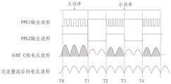
FIG. 3 is a waveform diagram of a method of operation of an electromagnetic heating system;
FIG. 4 is a circuit diagram of a prior art electromagnetic heating system;
FIG. 5 is a graph of the voltage and current waveforms of a PPG1 control signal and an IGBT in the prior art;
fig. 6 is a waveform diagram of the operation principle of the L C oscillation circuit.
Detailed Description
In order to make the technical means, the creation characteristics, the achievement purposes and the effects of the invention easy to understand, the invention is further described with the specific embodiments.
As shown in fig. 1 and 2, an electromagnetic heating system includes a control module 100, a power switch tube driving circuit module 200, power switch tube modules 300 and L C resonant modules 400, wherein the L C resonant module 400 is connected with a circuit input end a and a circuit input end B, the L C resonant module 400 further includes a switching capacitor circuit module 401, the switching capacitor circuit module 401 is provided with a power switch component, the switching capacitor circuit module 401 is connected with the control module 100, the power switch tube driving circuit module 200 is connected with the control module 100 and the power switch tube module 300, and the power switch tube module 300 is connected with the L C resonant module 400.
The power switch tube module 300 is provided with an IGBT (insulated gate bipolar transistor), the C pole of the IGBT is connected to a C resonance module 400, the E pole of the IGBT is connected to a circuit input B end, the G pole of the IGBT is connected to a power switch tube driving circuit module 200, a diode ZD and a resistor R of the power switch tube driving circuit module 200 are connected in parallel and then connected to the G pole and the E pole of the IGBT, one end of the resistor R is connected to a diode ZD negative pole and a resistor R, the other end of the resistor R is connected to an E pole of a triode Q and an E pole of the triode Q, the resistor R, the triode Q and the triode Q are connected in series to form a series circuit, one end of the series circuit is connected to a power supply VCC, the other end of the series circuit is connected to a diode positive pole and a resistor R, the C pole of the triode Q is connected to one end of a resistor R, the other end of the resistor R is connected to the power supply VCC, the B pole of the triode Q and the E pole of the triode Q are connected to a resistor R, the diode positive pole of the resistor R and the resistor R, the resistor R is connected to a PPG trigger module 100, the PPG trigger module 100 is connected to a PPG, the PPG trigger module 100 and a PPG trigger module 100, and a PPG trigger module 100 is provided with a PPG trigger module, and a PPG trigger module 100 module, and a PPG module 100 module, and a PP.
The power switch component Q4 may be a power switch component such as a triode, a MOS transistor, or an IGBT. As shown in fig. 2, the power switch device Q4 is preferably a MOS transistor, and the port No. 1, the port No. 2, and the port No. 3 of the power switch device Q4 correspond to the D pole, the S pole, and the G pole of the MOS transistor, respectively. The D pole of the MOS tube is connected with the capacitor C2, the S pole and the G pole of the MOS tube are connected with the resistor R8, one end of the resistor R7 is connected with the resistor R8 and the G pole of the MOS tube, and the other end is connected with the control module 100.
As shown in fig. 3, a method for operating an electromagnetic heating system includes the following steps:
1) when the power switch module works in a high-power state, in a time period from T0 to T1, the PPG1 of the control module 100 sends out a control signal, and the IGBT is controlled to be periodically switched on and switched off through the power switch tube driving circuit module 200;
2) when the direct current resonant module works in a low-power state, at the zero-crossing time T1 of alternating current, the PPG1 outputs a high level firstly, the IGBT is cut off, the delay is 5us-3ms, the PPG2 outputs a low level, the power switch component Q4 is cut off, the direct current input capacitor C2 is disconnected from the L C resonant module 400 circuit, and the direct current input capacitor C2 stops charging;
3) waiting for the next alternating current zero-crossing time T2, sending a high level by PPG2, turning on a power switch component Q4, and switching on a direct current input capacitor C2 into the L C resonance module 400 again, wherein after delaying for 5us-3ms, the PPG1 sends out a control signal to control the IGBT to be turned on and off periodically through the power switch tube driving circuit module 200;
4) once again, at the time T3, the ac zero-crossing point returns to step 2).
As can be seen from the figure, the working state at the time of T1 is repeated at the time of T3, the working state at the time of T2 is repeated at the time of T4, and the aim of reducing electromagnetic EMI and noise can be achieved by periodic repeated working.
The PPG1 acts before the PPG2 in the step 3), and the same beneficial effect can be achieved.
As shown in fig. 2) and 3) intervals and 3) and 4) intervals are two zero-crossing time intervals, in practical operation, the interval between 2) and 3) and the interval between 3) and 4) may be one or more zero-crossing points of the alternating current.
With reference to the circuit diagram of fig. 4, the IGBT collector voltage, current waveform diagrams of fig. 5 and fig. 6, L C resonant operation principle is as follows:
1) when the PPG1 signal is added to the collector of the IGBT at t1-t2, the IGBT is in saturated conduction, current i1 flows from the power supply through L1, and the current is not allowed to change suddenly due to coil inductance, so that the current i1 rises linearly at t1-t 2;
2) at t2, the PPG1 signal ends, the IGBT turns off, i1 cannot immediately become 0, again due to inductive reactance, and the capacitor C1 is charged, resulting in a charging current i 2;
3) at time t3, the capacitor C1 is fully charged, the current becomes 0, at this time, the magnetic field energy of L1 is completely converted into the electric field energy of the capacitor C1, right negative and left positive appear at the two ends of the capacitor C1, the amplitude reaches the peak voltage, and the voltage appearing between CE electrodes of the IGBT is actually the reverse stroke pulse peak voltage plus the power supply voltage;
4) at time t3-t4, the capacitor C1 finishes discharging through L1, i3 reaches the maximum value, the voltage at two ends of the capacitor C1 disappears, at this time, the electric energy in the capacitor C1 is converted into the magnetic energy in L1, i3 cannot be changed into 0 immediately due to inductive reactance, so that the electromotive force at two ends of L1 is reversed, namely the potential at two ends of L1 is positive right and negative left, and due to the existence of the IGBT body diode, the capacitor C1 cannot continue reverse charging, but flows back through the capacitor C2 and the IGBT diode to form a current i4
5) At time t4, the PPG1 starts to arrive at the second pulse, but at this time, the IGBT UE is positive, UC is negative, and the IGBT is in a reverse bias state, so the IGBT cannot conduct until i4 decreases to 0, and the magnetic energy in L1 is discharged, that is, the IGBT starts to conduct for the second time until t 5.
According to the L C oscillation working principle, the capacitor C2 is cut off at a proper time, the voltage of an IGBT collector at the moment of opening the IGBT is reduced, and the IGBT is in a soft switching state, so that the amplitude of large impact current generated in a hard switching state is reduced, electromagnetic EMI interference and noise are reduced, and the IGBT is ensured to work in a safe current range.
The scheme provides that a switching capacitor circuit module 401 is arranged at an L C resonance module 400, when the IGBT is to be switched on, the switching capacitor circuit module 401 is started firstly, a capacitor C2 is disconnected from the L C resonance module 400, the voltage of the IGBT collector is reduced, then the IGBT is started again, the IGBT works in a soft switching state, then the capacitor C2 is connected to the L C resonance module 400 again, the circuit restores to a normal working state, and a power switching tube works in the soft switching state, so that the amplitude of large impact current generated in a hard switching state is reduced, electromagnetic interference (EMI) and noise are reduced, and the power switching tube is guaranteed to work in a safe current range.
It will be understood by those of ordinary skill in the art that the foregoing embodiments are specific examples for carrying out the invention, and that various changes in form and details may be made therein without departing from the spirit and scope of the invention in practice.
Claims (3)
1. A method of operating an electromagnetic heating system, comprising the steps of:
1) when the power switch tube module works in a high-power state, the PPG1 of the control module sends a control signal, and the IGBT of the power switch tube module is controlled to be periodically switched on and switched off through the power switch tube driving circuit module, the PPG2 of the control module outputs high level, so that the power switch element Q4 is always switched on, and the direct-current input capacitor C2 is connected into the L C resonance module;
2) when the direct current input capacitor works in a low-power state, at the zero crossing time of alternating current, the PPG1 outputs a high level firstly, the IGBT is cut off, the delay is 5us-3ms, the PPG2 outputs a low level, the power switch component Q4 is cut off, the direct current input capacitor C2 is disconnected from the L C resonance module circuit, and the direct current input capacitor C2 stops charging;
3) when the next alternating current zero-crossing time is waited, the PPG2 sends out high level, the power switch component Q4 is conducted, the direct current input capacitor C2 is connected into the L C resonance module again, and after 5us-3ms of delay, the PPG1 sends out a control signal to control the IGBT to be conducted and cut off periodically through the power switch tube driving circuit module;
4) and returning to the step 2) at the zero-crossing time of the alternating current once again.
2. The operating method of an electromagnetic heating system according to claim 1, wherein the PPG1 precedes the PPG2 in step 3).
3. A method of operating an electromagnetic heating system as claimed in claim 1, wherein the time interval between step 2) and step 3) and the time interval between step 3) and step 4) is one or more zero-crossing points of the alternating current.
Priority Applications (1)
| Application Number | Priority Date | Filing Date | Title |
|---|---|---|---|
| CN201710529872.0A CN107172733B (en) | 2017-07-03 | 2017-07-03 | Electromagnetic heating system and working method thereof |
Applications Claiming Priority (1)
| Application Number | Priority Date | Filing Date | Title |
|---|---|---|---|
| CN201710529872.0A CN107172733B (en) | 2017-07-03 | 2017-07-03 | Electromagnetic heating system and working method thereof |
Publications (2)
| Publication Number | Publication Date |
|---|---|
| CN107172733A CN107172733A (en) | 2017-09-15 |
| CN107172733B true CN107172733B (en) | 2020-07-28 |
Family
ID=59827377
Family Applications (1)
| Application Number | Title | Priority Date | Filing Date |
|---|---|---|---|
| CN201710529872.0A Active CN107172733B (en) | 2017-07-03 | 2017-07-03 | Electromagnetic heating system and working method thereof |
Country Status (1)
| Country | Link |
|---|---|
| CN (1) | CN107172733B (en) |
Families Citing this family (3)
| Publication number | Priority date | Publication date | Assignee | Title |
|---|---|---|---|---|
| CN110493904B (en) * | 2018-05-14 | 2021-07-30 | 深圳市鑫汇科股份有限公司 | Electromagnetic induction heating control method and electromagnetic heating equipment |
| CN109640428A (en) * | 2019-01-20 | 2019-04-16 | 邱晖 | A kind of controlling circuit of electromagnetic furnace |
| CN111507034B (en) * | 2020-04-15 | 2023-05-16 | 南方电网电力科技股份有限公司 | Method and system for calculating time-varying characteristics of lightning arrester temperature field under impact load |
Citations (7)
| Publication number | Priority date | Publication date | Assignee | Title |
|---|---|---|---|---|
| CN203104830U (en) * | 2012-12-31 | 2013-07-31 | 美的集团股份有限公司 | Electromagnetic heating apparatus |
| CN205430653U (en) * | 2016-02-02 | 2016-08-03 | 佛山市顺德区美的电热电器制造有限公司 | Electromagnetic heating device and heating control circuit thereof |
| CN106136843A (en) * | 2015-04-07 | 2016-11-23 | 佛山市顺德区美的电热电器制造有限公司 | Cooking apparatus and the electric heater unit for cooking apparatus |
| CN106162970A (en) * | 2015-04-07 | 2016-11-23 | 佛山市顺德区美的电热电器制造有限公司 | Electromagnetic heater and the electromagnetic oven with it |
| CN106162971A (en) * | 2015-04-07 | 2016-11-23 | 佛山市顺德区美的电热电器制造有限公司 | Electromagnetic heater and the electromagnetic oven with it |
| KR20170019888A (en) * | 2015-08-13 | 2017-02-22 | 주식회사 윌링스 | Quasi-resonant induction heating circuit having a capacitor switch |
| CN106686786A (en) * | 2015-11-11 | 2017-05-17 | 佛山市顺德区美的电热电器制造有限公司 | Electromagnetic heating apparatus and control method and control circuit thereof |
-
2017
- 2017-07-03 CN CN201710529872.0A patent/CN107172733B/en active Active
Patent Citations (7)
| Publication number | Priority date | Publication date | Assignee | Title |
|---|---|---|---|---|
| CN203104830U (en) * | 2012-12-31 | 2013-07-31 | 美的集团股份有限公司 | Electromagnetic heating apparatus |
| CN106136843A (en) * | 2015-04-07 | 2016-11-23 | 佛山市顺德区美的电热电器制造有限公司 | Cooking apparatus and the electric heater unit for cooking apparatus |
| CN106162970A (en) * | 2015-04-07 | 2016-11-23 | 佛山市顺德区美的电热电器制造有限公司 | Electromagnetic heater and the electromagnetic oven with it |
| CN106162971A (en) * | 2015-04-07 | 2016-11-23 | 佛山市顺德区美的电热电器制造有限公司 | Electromagnetic heater and the electromagnetic oven with it |
| KR20170019888A (en) * | 2015-08-13 | 2017-02-22 | 주식회사 윌링스 | Quasi-resonant induction heating circuit having a capacitor switch |
| CN106686786A (en) * | 2015-11-11 | 2017-05-17 | 佛山市顺德区美的电热电器制造有限公司 | Electromagnetic heating apparatus and control method and control circuit thereof |
| CN205430653U (en) * | 2016-02-02 | 2016-08-03 | 佛山市顺德区美的电热电器制造有限公司 | Electromagnetic heating device and heating control circuit thereof |
Also Published As
| Publication number | Publication date |
|---|---|
| CN107172733A (en) | 2017-09-15 |
Similar Documents
| Publication | Publication Date | Title |
|---|---|---|
| TWI489751B (en) | Power factor correction boost circuit and synchronous rectifier | |
| CN107172733B (en) | Electromagnetic heating system and working method thereof | |
| CN103795260A (en) | Non-complementary flyback active clamp converter | |
| US20140063593A1 (en) | Capacitor discharge pulse drive circuit with fast recovery | |
| CN103424602B (en) | Based on the secondary winding current testing circuit of source drive | |
| CN102594101A (en) | Isolated rapid turn-off metal oxide field effect transistor (MOFET) driving circuit | |
| CN203278782U (en) | Drive and protection circuit of high-frequency low-power MOSFET | |
| CN202524281U (en) | Isolated rapid turn-off oxide field effect transistor (MOFET) driving circuit | |
| CN104539141A (en) | Switching power supply double-pulse pulse width constraint circuit and implement method thereof | |
| CN203814013U (en) | LED driving circuit adopting single-end zero crossing detection | |
| CN204518108U (en) | Electromagnetic Heating control circuit and electromagnetic appliance | |
| US11862416B2 (en) | Hybrid DC circuit breaker | |
| CN109450418B (en) | IGBT isolation driving circuit with switch control unit and control method thereof | |
| CN114572029A (en) | Pre-charging device and power supply system | |
| WO2017125055A1 (en) | Hybrid switch | |
| CN107277954B (en) | Electromagnetic heating circuit and control method thereof | |
| CN104811174A (en) | Power switch tube driving circuit capable of regulating switching speed of power switch tube | |
| CN210536285U (en) | Active clamping circuit internally arranged in drive IC for protecting IGBT | |
| GB2535115A (en) | Flyback switching power supply circuit and backlight driving device applying same | |
| CN214069805U (en) | Front-end protection device for switching power supply | |
| CN211908673U (en) | Load driving circuit and electronic equipment | |
| CN102097253B (en) | Control circuit | |
| CN106601549A (en) | DC relay protection control method and circuit | |
| CN203465339U (en) | Secondary winding current detection circuit based on source drive | |
| JP2009261117A (en) | Switching power supply unit |
Legal Events
| Date | Code | Title | Description |
|---|---|---|---|
| PB01 | Publication | ||
| PB01 | Publication | ||
| SE01 | Entry into force of request for substantive examination | ||
| SE01 | Entry into force of request for substantive examination | ||
| GR01 | Patent grant | ||
| GR01 | Patent grant | ||
| TR01 | Transfer of patent right |
Effective date of registration: 20231010 Address after: No. 2977, Jingliu Road, Linjiang Street, Qiantang District, Hangzhou City, Zhejiang Province 311228 Patentee after: Hangzhou yinglete Intelligent Technology Co.,Ltd. Address before: 313300 Tangpu Industrial Park, Anji Economic Development Zone, Anji County, Huzhou City, Zhejiang Province Patentee before: ANJI SINODOD INTELLIGENT TECHNOLOGY CO.,LTD. |
|
| TR01 | Transfer of patent right |